APPENDIX A SWM FACILITY DESIGN DETAILS APPENDIX B HYDROLOGIC MODELING OUTPUT APPENDIX C WATER BUDGET CALCULATIONS APPENDIX D GEOTECHNICAL INVESTIGATION
DRAWINGS MTE Drawing No. 39168-202-EC1.1 – Existing Conditions Plan ..................................... Encl. Draft Plan (June 27, 2016) by Labreche Patterson & Associates Inc. .............................. Encl.
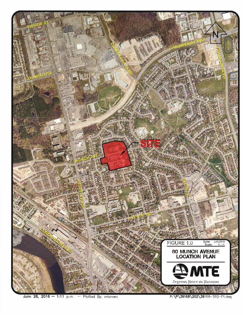
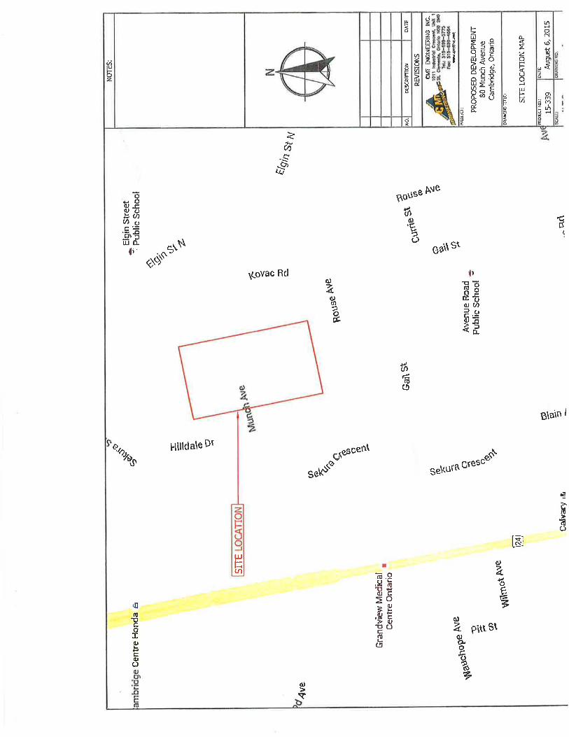
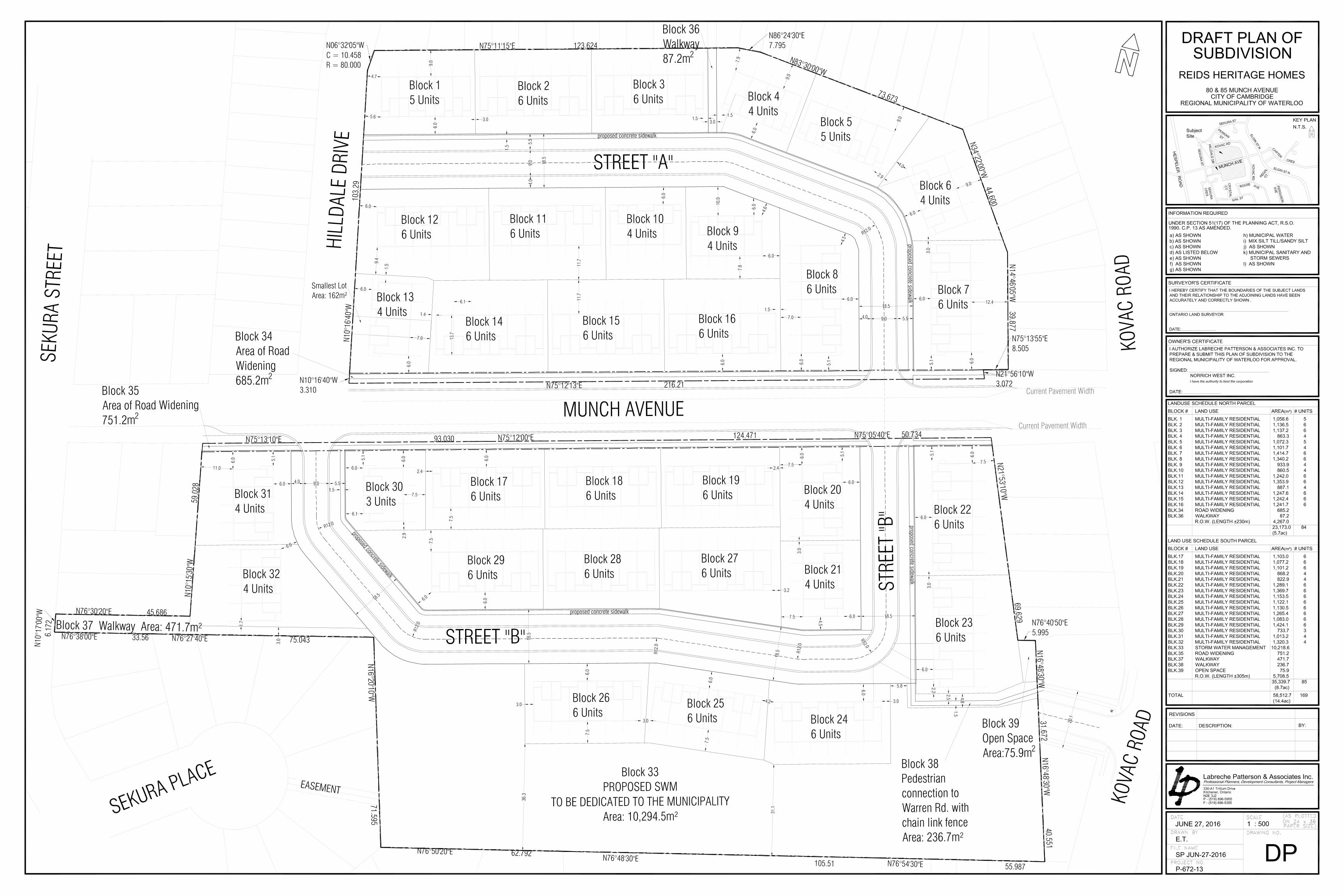
1.0 INTRODUCTION 1.1 Overview MTE Consultants Inc. (MTE) was retained by Norrich West Inc. to complete a Preliminary Stormwater Management (SWM) Report to support the proposed 80 Munch Avenue Residential Subdivision, located in the City of Cambridge. The site is currently seeking Zone Change and Draft Plan Approval. This preliminary report addresses comments received to date from all agencies arising from the pre-consultation process and subsequent correspondence. The subject site is approximately 5.85 ha (14.46 ac) generally bounded by Kovac Road to the north and east, Gail Street to the south, and Sekura Street to the west as shown on Figure 1.0 - Location Plan. The site is bisected into north and south parcels by Munch Avenue which runs from Elgin Street (major collector), east to Hespeler Road (Regional Road 24). The subject site is surrounded entirely by existing residential development. Currently, the north parcel has two storm water management dry ponds serving the existing residential lands to the north of the site. The larger pond drains to an existing 300m diameter storm sewer that connects with a 675mm diameter storm sewer on Kovac Road. The smaller pond on the NW corner of Munch Avenue and Hilldale Drive drains south, across Munch Avenue, in a 300mm storm sewer to an existing ditch system on the south side of Munch Avenue. Surface flow from the south parcel and the ditch system infiltrates on site and the remainder is picked up by rear yard swales within the surrounding residential lots. It is proposed to develop the property as an in-fill multi-residential townhouse development. A single stormwater management facility is proposed for the subdivision, located along the south boundary of the south parcel. The SWM Facility will outlet directly to an existing storm sewer on Sekura Place, which in turn flows to the Grand River. This report presents the proposed plan detailing the stormwater quality and quantity control, as well as infiltration, which will be provided for the 80 Munch Avenue development.
1.2 Background The study area is located within the Greenway-Chaplin Neighbourhood Plan. The City of Cambridge Official Plan designates the area as, 2. Residential Designation - “low/medium density residential”. The subject site does not fall within the boundary of an existing subwatershed plan; therefore a SWM plan had been established by the City of Cambridge and Grand River Conservation Authority (GRCA) through a pre-consultation process. This report provides the necessary SWM support for this plan. 1.3 Purpose of Study The purpose of this study is to develop a comprehensive stormwater management strategy for the current development proposal, which is acceptable to the City of Cambridge, Region of Waterloo, the Grand River Conservation Authority (GRCA), and the Ministry of the Environment (MOE).
1.4 Objectives
The objective of this stormwater management plan is to ensure that the proposed development includes the necessary controls to protect the hydrology and water quality of the receiving water systems. The primary objectives of this study are as follows:
Establish criteria for the management of stormwater runoff from the study area.
Assess impacts of development on the peak flow runoff from the study area.
Recommend a comprehensive plan for controlling the quantity and quality of stormwater runoff from the study area.
Recommend a strategy for controlling the volume of infiltration to groundwater.
2.0 EXISTING CONDITIONS AND BACKGROUND INFORMATION 2.1 Existing Land Uses
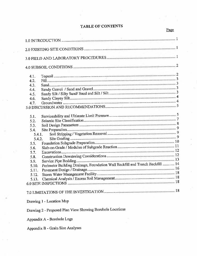
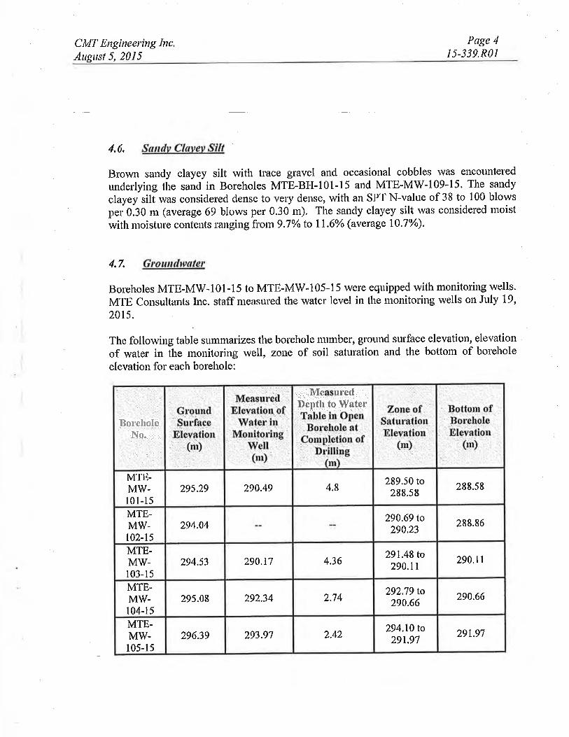
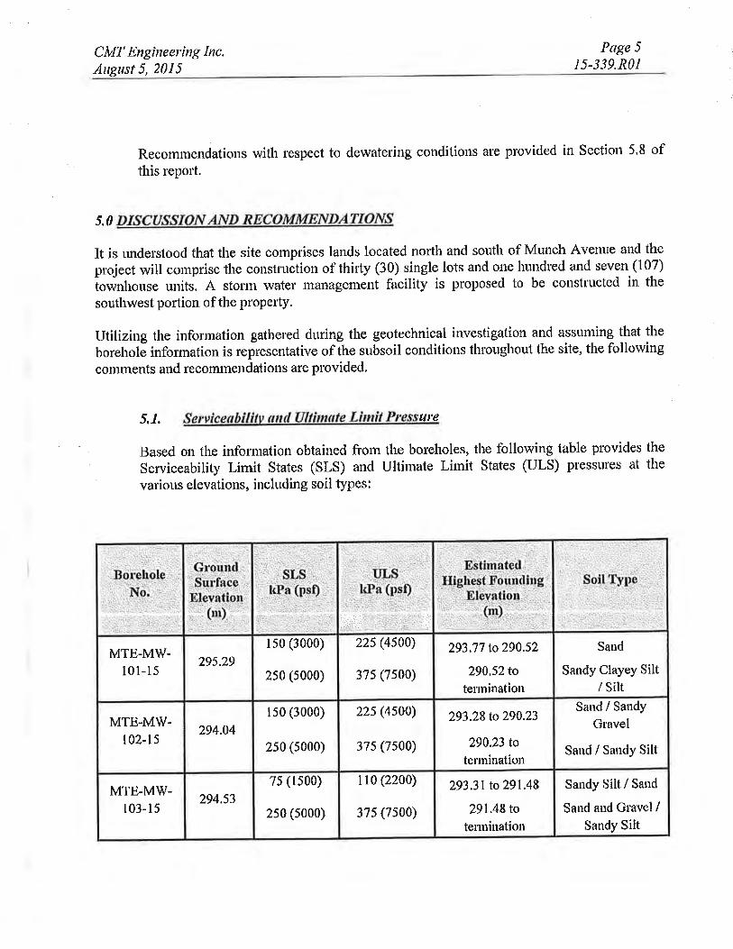
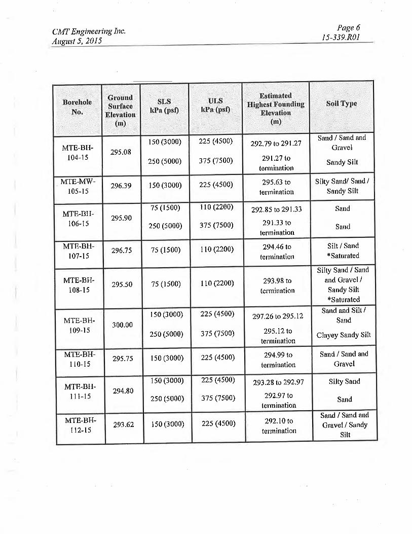
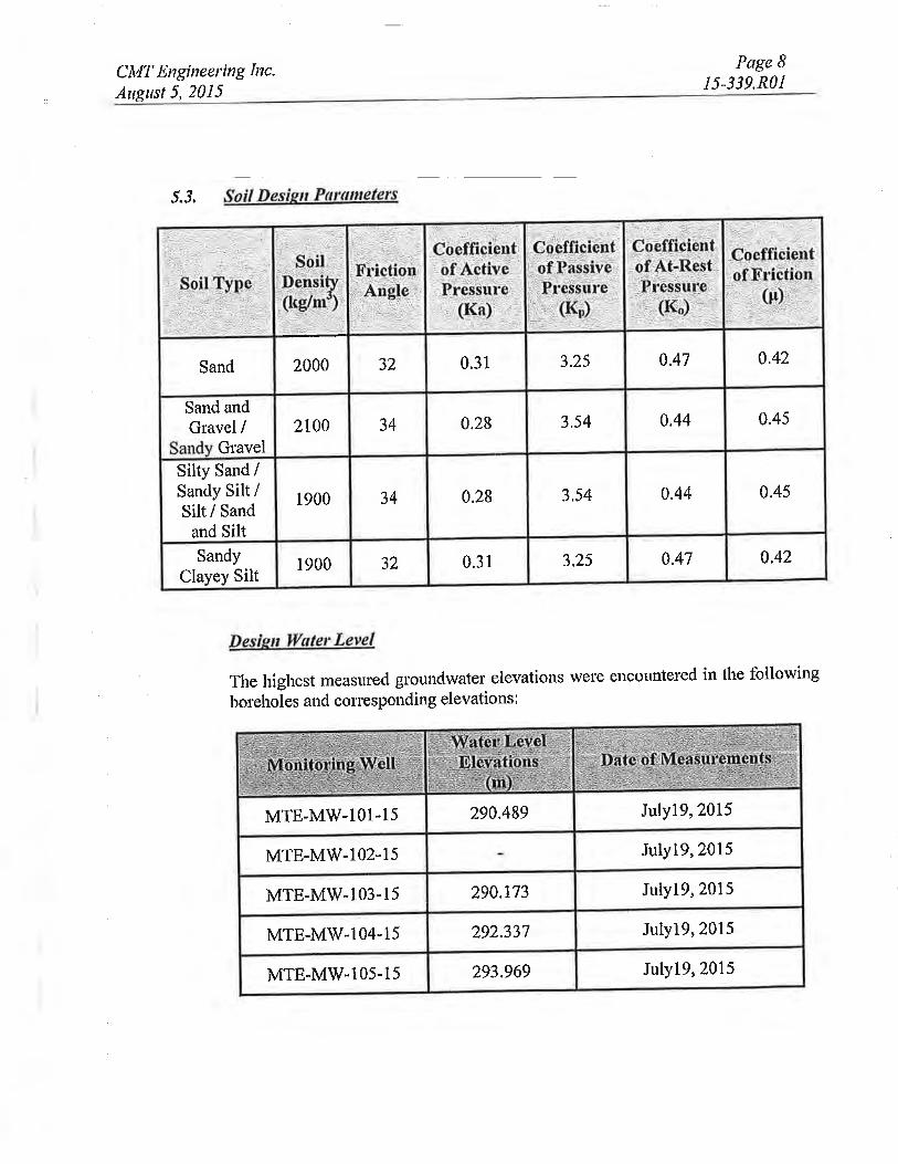
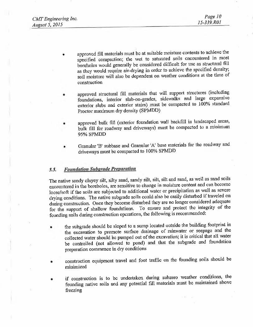
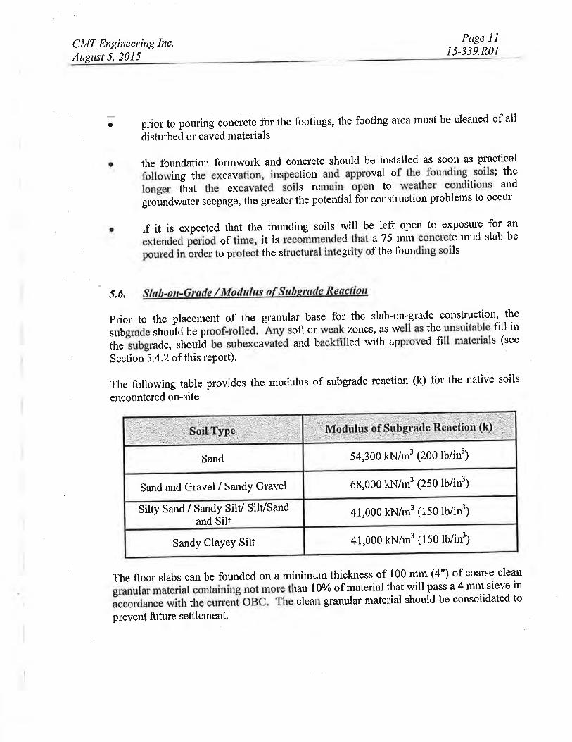
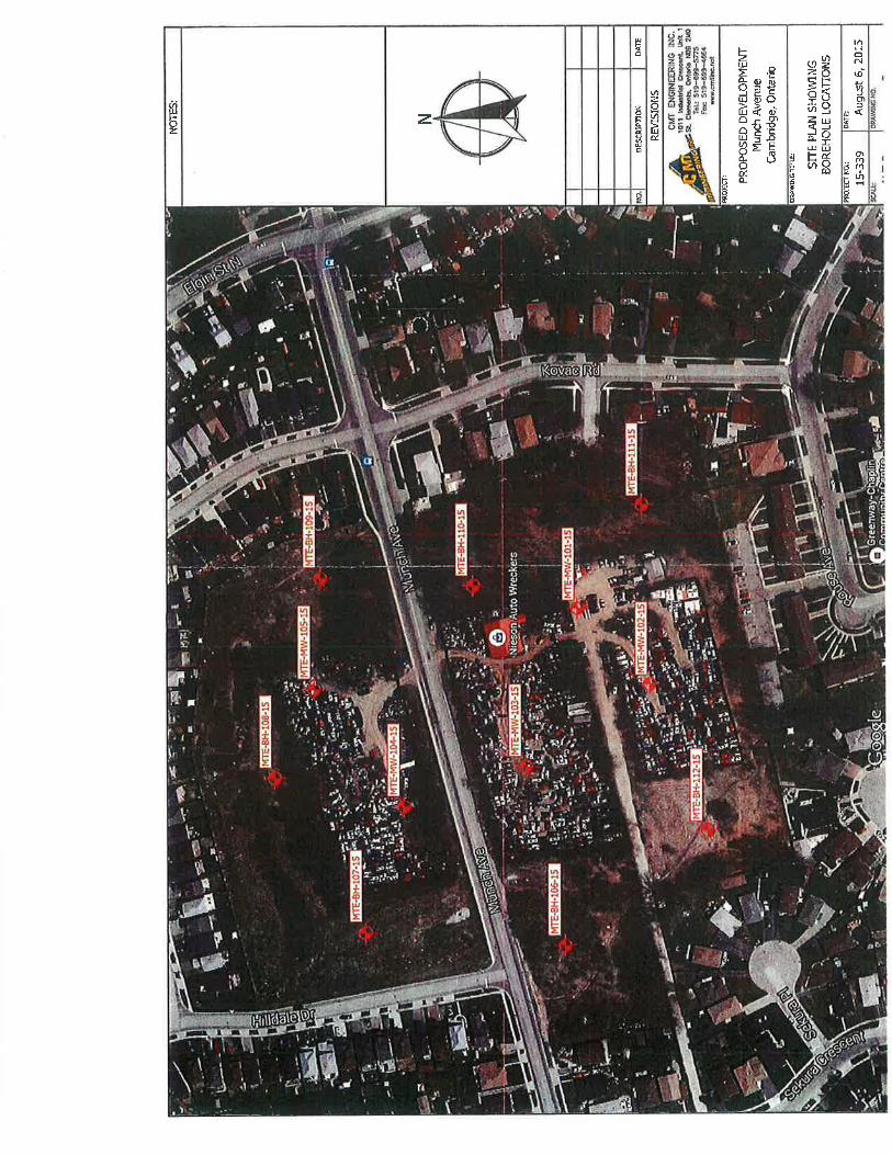
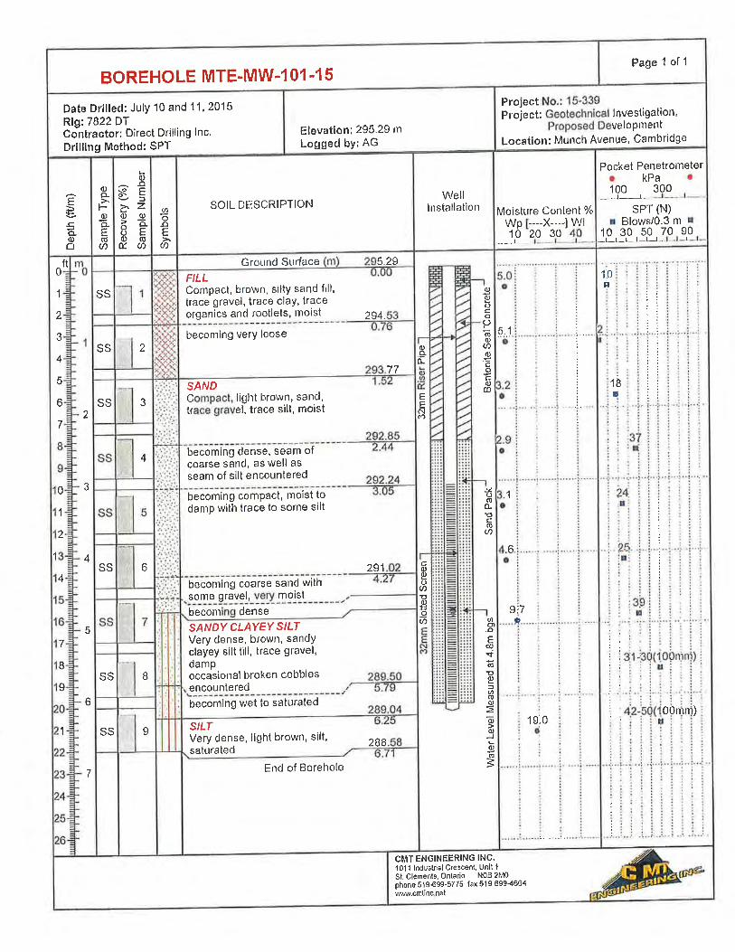
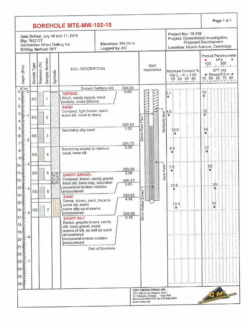
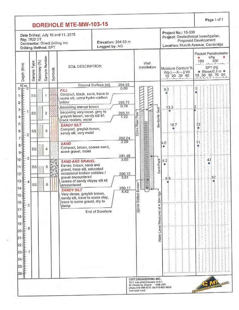
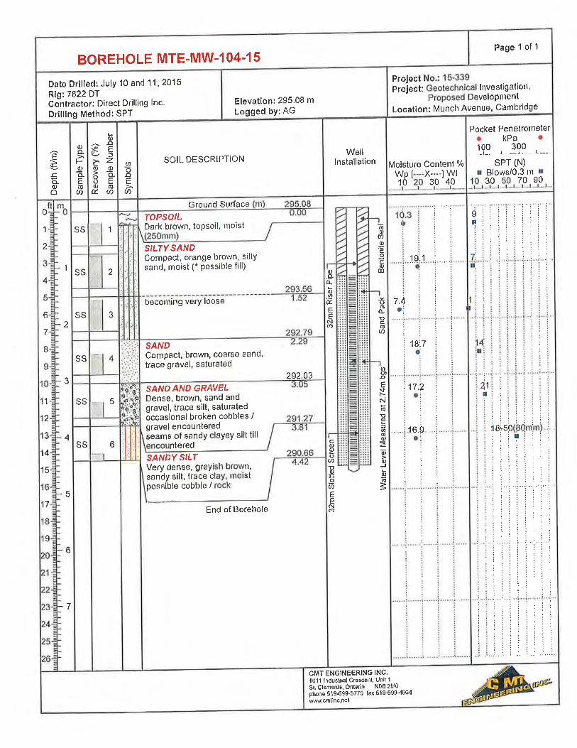
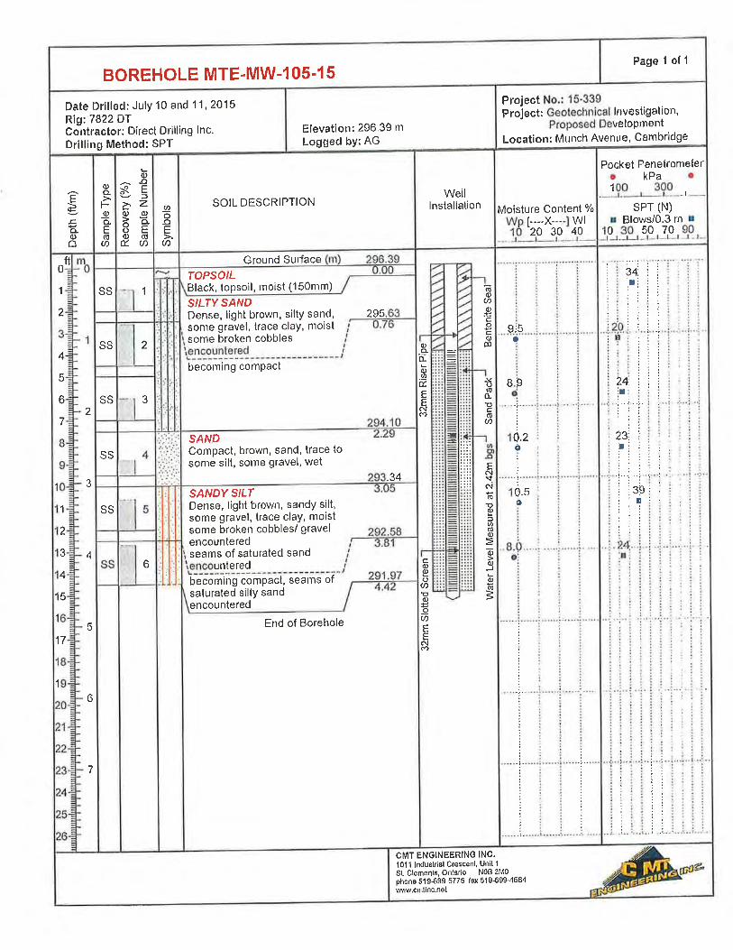
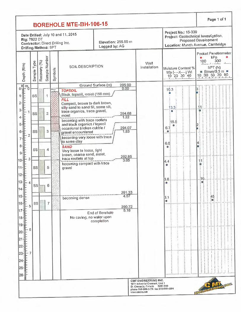
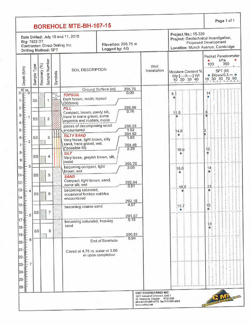
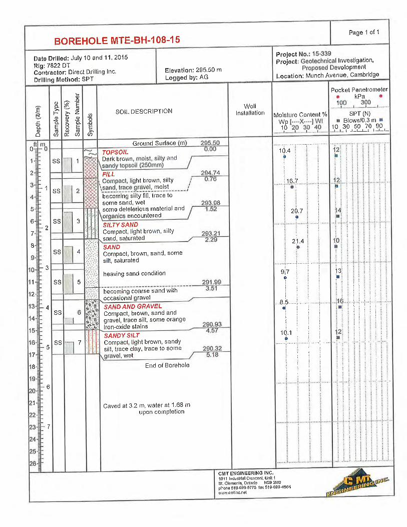
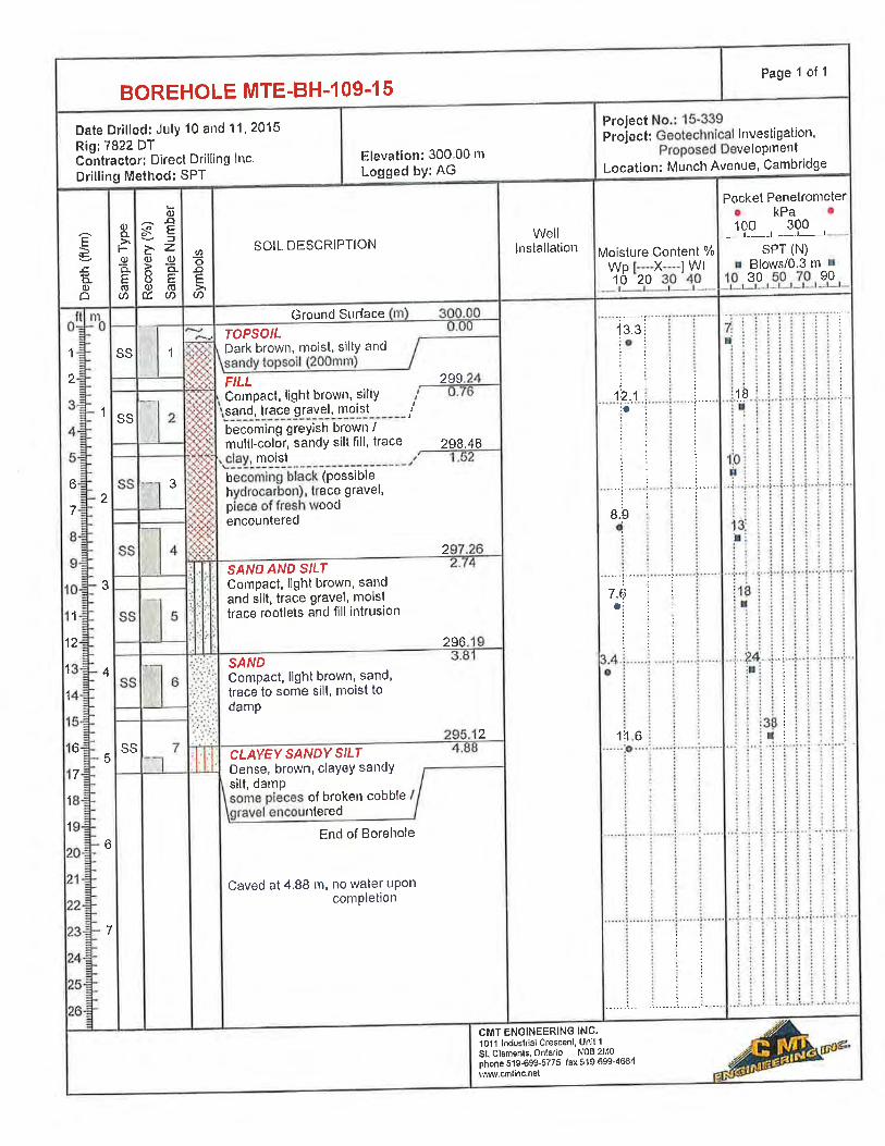
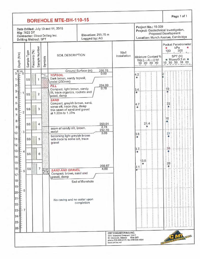
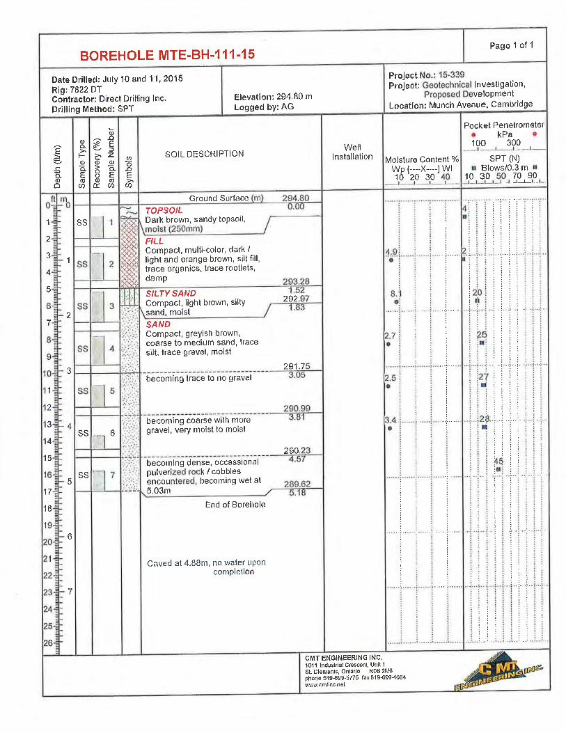
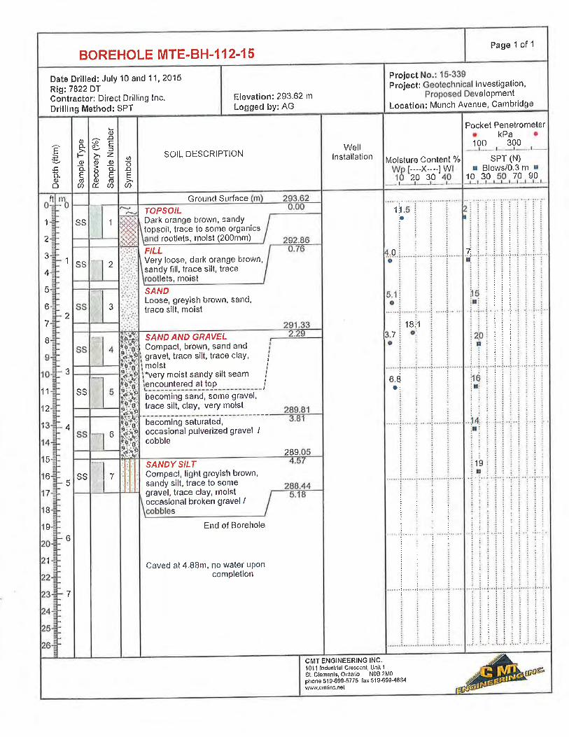
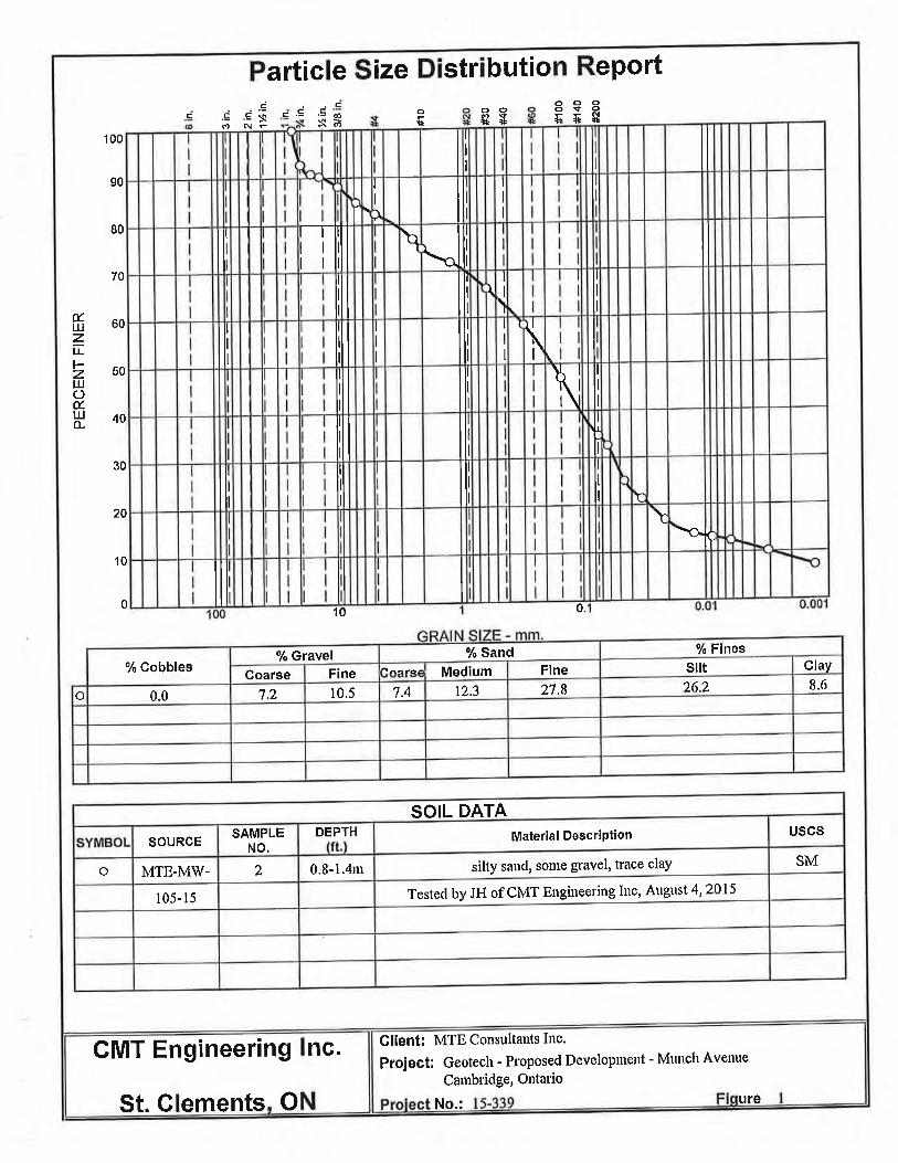
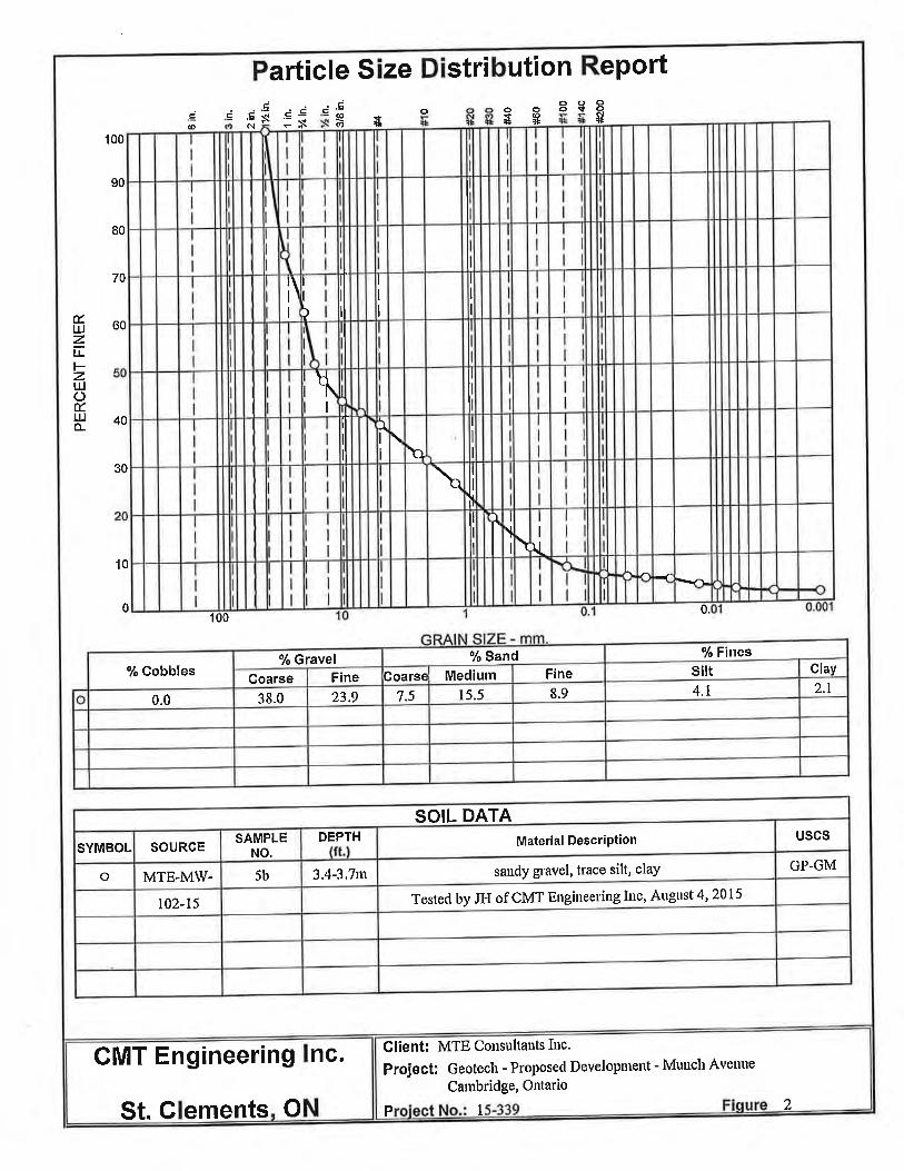
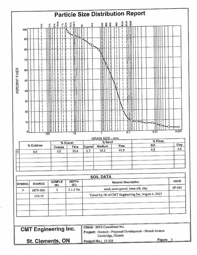
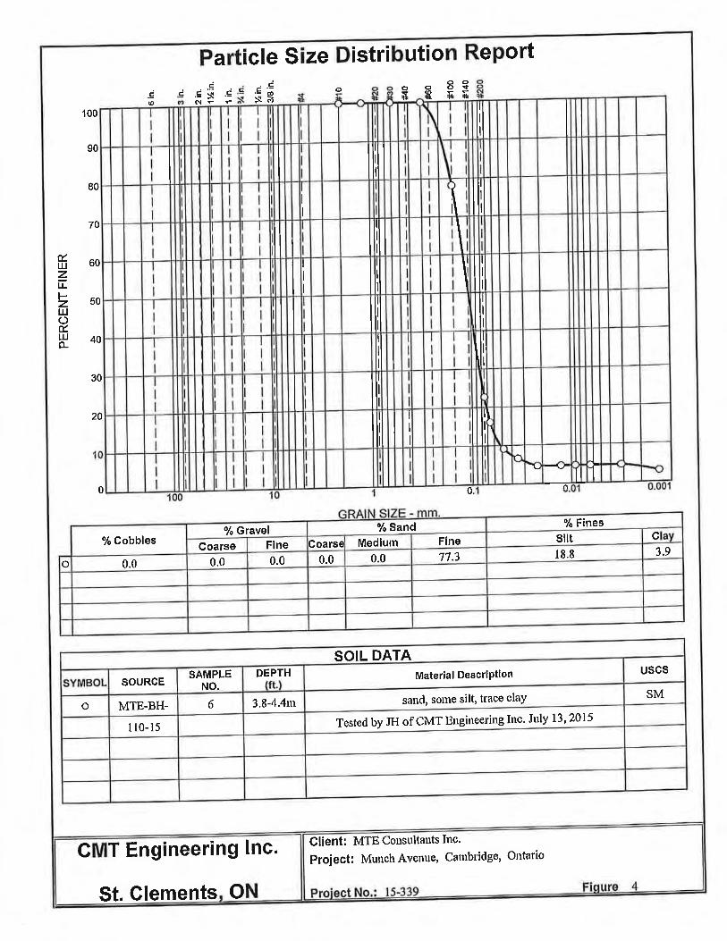
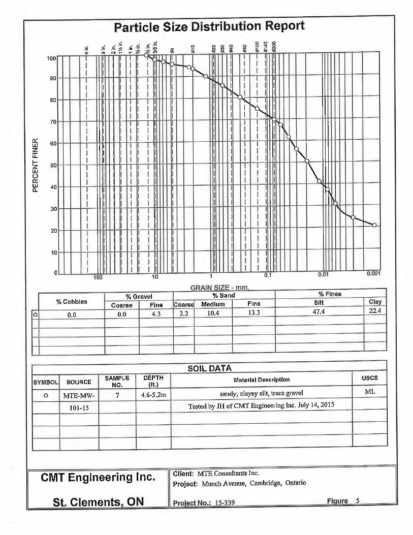
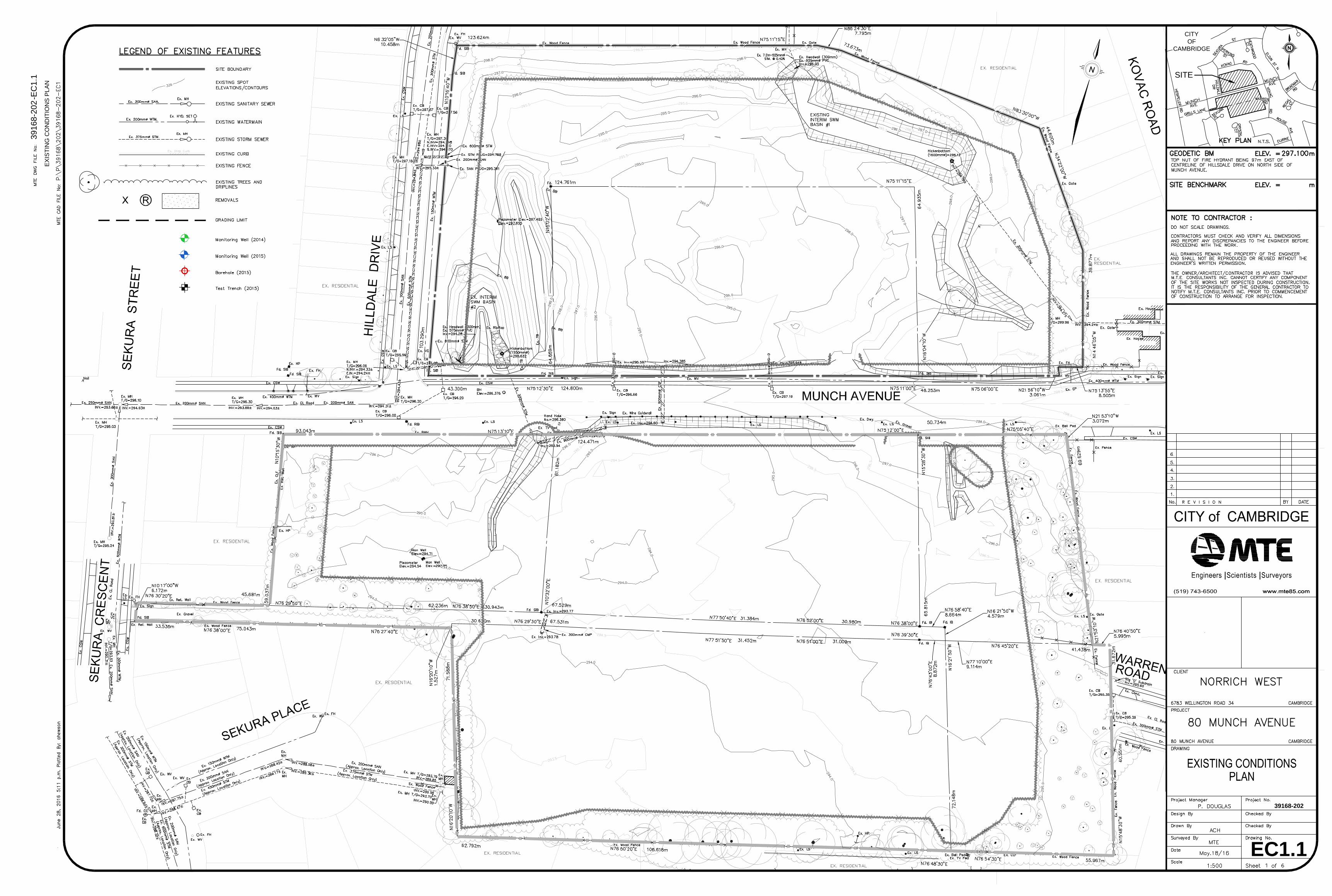
The subject lands are surrounded by existing single family and townhouse residential lots. The lands to be developed are in two parcels, a north and south parcel divided by Munch Avenue running east west. The north parcel, adjacent the existing single family lots, is open space containing two dry ponds, with a centrally located abandoned auto wrecker yard immediately north of Munch Avenue. The south parcel, adjacent the existing residential lots, is also open space, with the other half of the centrally located abandoned auto wrecker yard immediately south of Munch Avenue. 2.2 Topographical Information MTE completed a detailed topographical survey of the site by total station in September 2015. The Existing Conditions Plan, MTE Drawing EC1.1, is enclosed. The overall gradient of the site is in a south-westerly direction. Two existing dry ponds are located in the north parcel, one along the north boundary which has a bottom of 295.25m and another along Hilldale Drive which has a bottom of 293.75m. There is a grade differential of approximately 7.3m between the highest point on the northeast corner of the site (300.50m) and the low point along the southwest boundary (293.2m). 2.3 Geotechnical and Hydrogeological Information In June 2015, CMT Engineering Inc. carried out a geotechnical investigation for the 80 Munch Avenue Subdivision for MTE Consultants Inc. The fieldwork for this investigation included the drilling of seven boreholes (BH106-15 to 112-15) and the advancement of five monitoring wells (MW101-15 to 105-15) on the subject property. The boreholes were drilled to depths of 4.42 m to 6.71 m. Based on the results of CMT’s detailed geotechnical investigation, the subsurface stratigraphy is described as topsoil overlying varying deposits of sand or sand and gravel which in turn overlies sandy silt. Nine of the twelve BH’s indicate fill, ranging in depth from 0.46m to 1.27m. The major soil component is sand and sand and gravel with some silt layers generally found at the 4-5m depth. Groundwater is generally perched in granular deposits over the silt layers. BH’s 107-15 and 108-15, located in the north parcel near the existing SWM basins showed water upon completion at a depth of 3.66m and 1.68m respectively. Variation in groundwater levels should also be expected from seasonal effects. Five MW’s were measured on July 19, 2015 with depths ranging from 2.42m to 4.80m. For the full Geotechnical Report and Borehole logs refer to Appendix D.
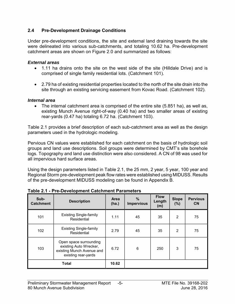
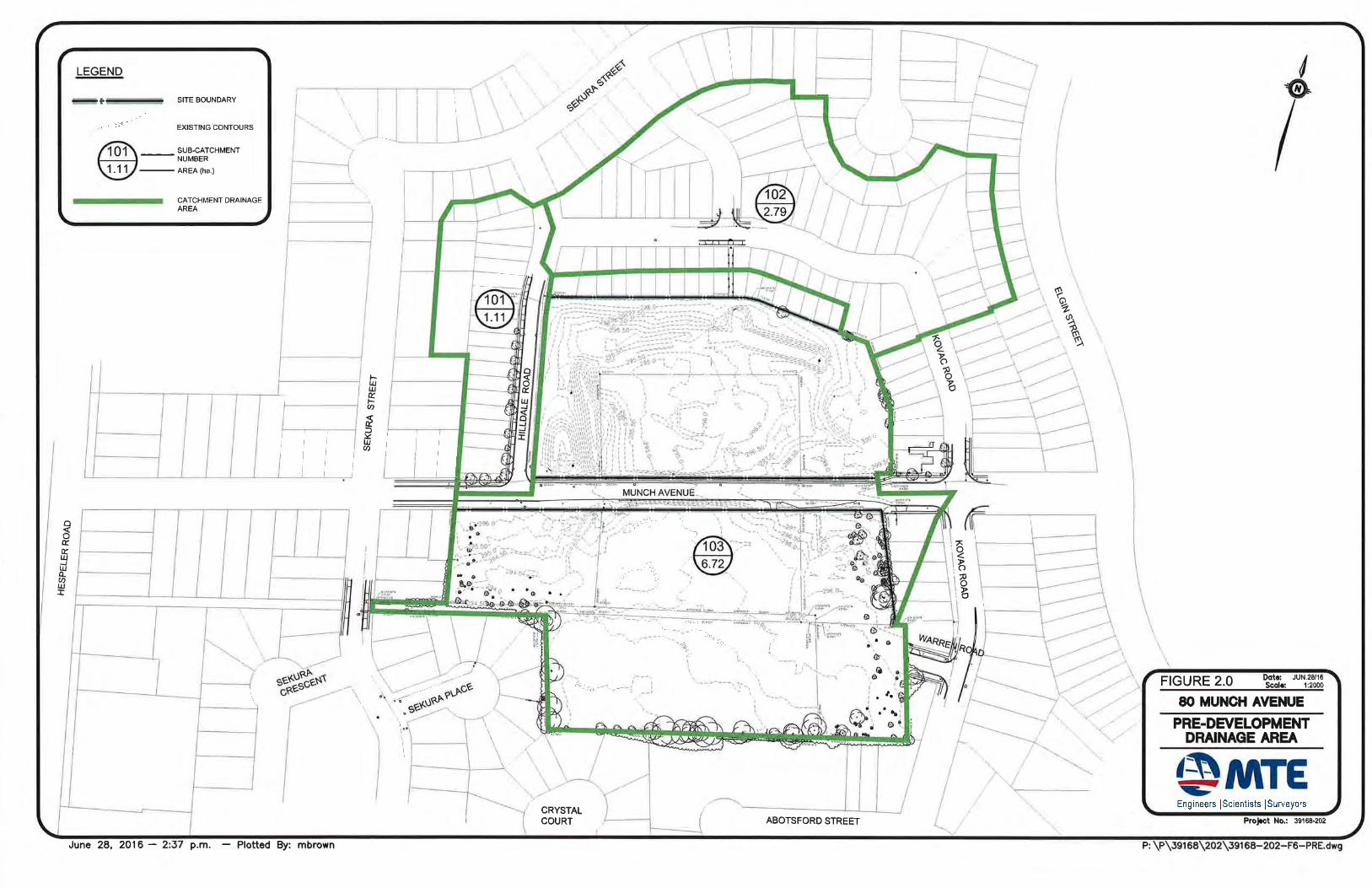
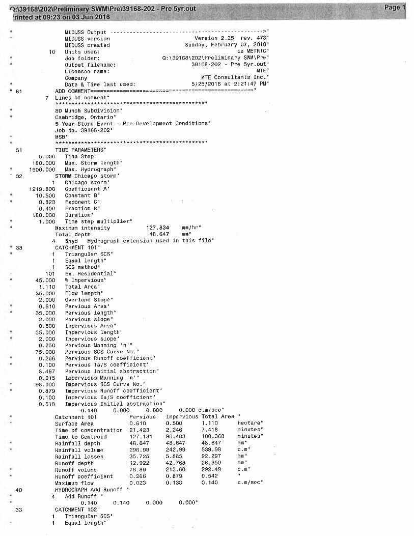
2.4 Pre-Development Drainage Conditions Under pre-development conditions, the site and external land draining towards the site were delineated into various sub-catchments, and totaling 10.62 ha. Pre-development catchment areas are shown on Figure 2.0 and summarized as follows: External areas
1.11 ha drains onto the site on the west side of the site (Hilldale Drive) and is comprised of single family residential lots. (Catchment 101).
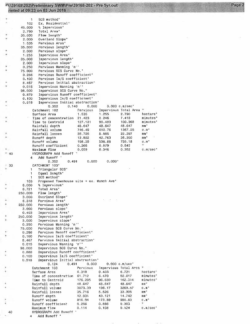
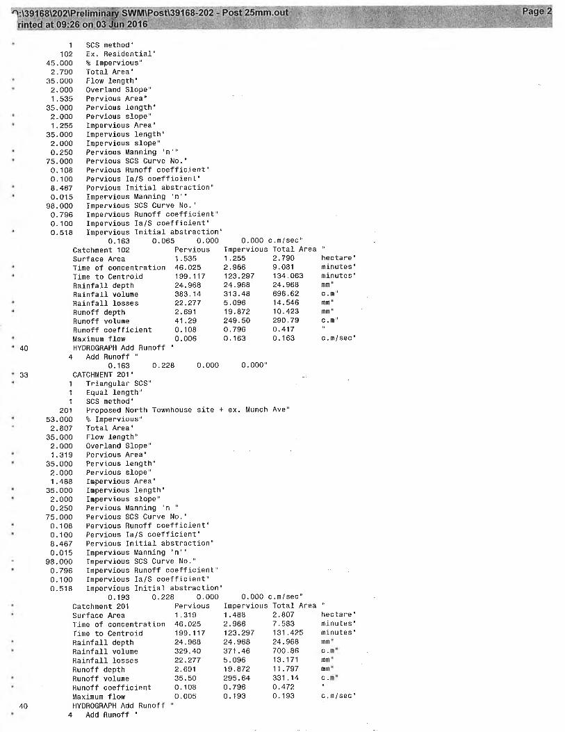
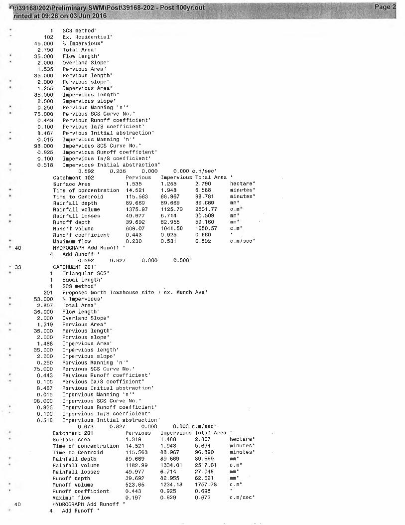
2.79 ha of existing residential properties located to the north of the site drain into the site through an existing servicing easement from Kovac Road. (Catchment 102).
Internal area
The internal catchment area is comprised of the entire site (5.851 ha), as well as, existing Munch Avenue right-of-way (0.40 ha) and two smaller areas of existing rear-yards (0.47 ha) totaling 6.72 ha. (Catchment 103).
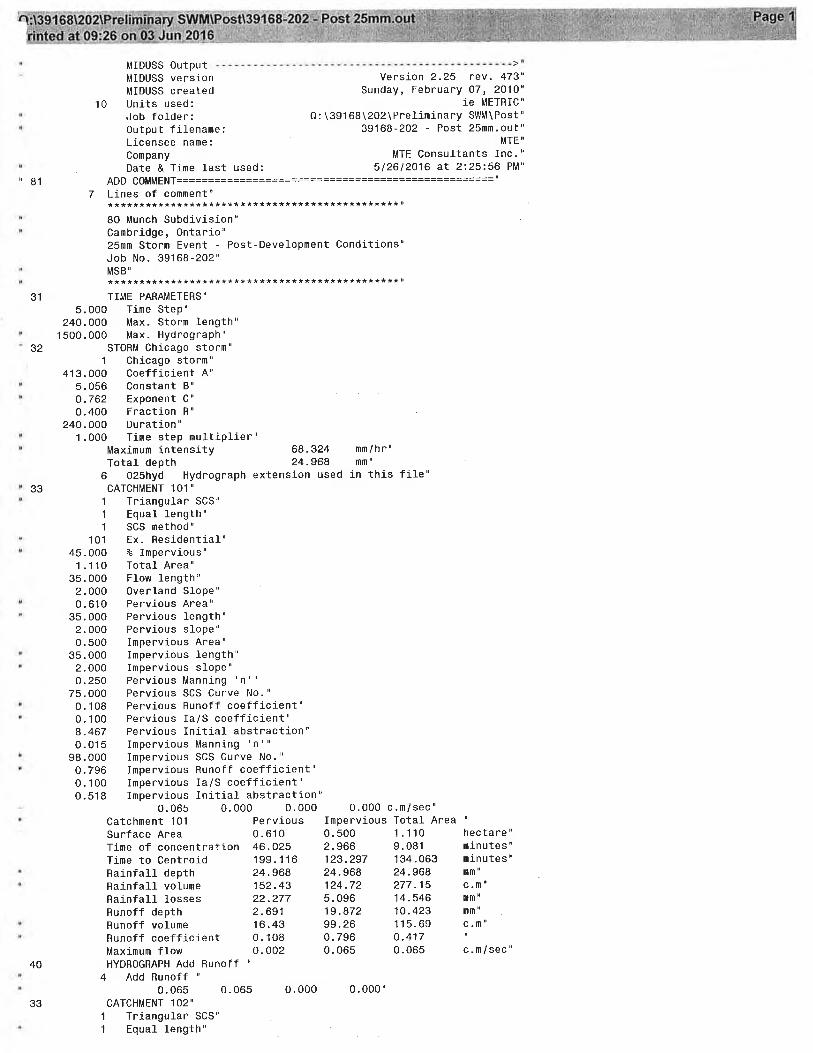
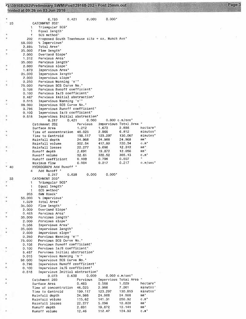
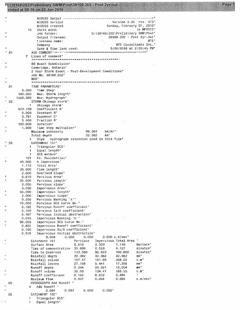
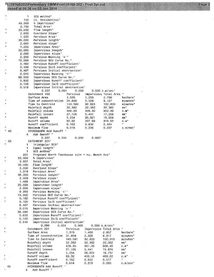
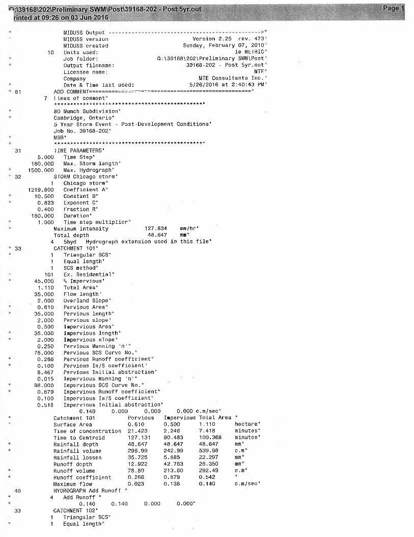
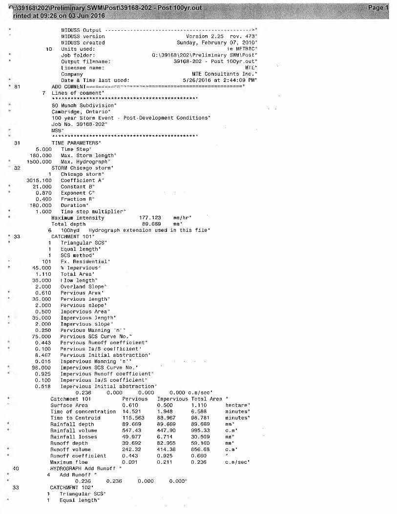
Table 2.1 provides a brief description of each sub-catchment area as well as the design parameters used in the hydrologic modeling. Pervious CN values were established for each catchment on the basis of hydrologic soil groups and land use descriptions. Soil groups were determined by CMT’s site borehole logs. Topography and land use distinction were also considered. A CN of 98 was used for all impervious hard surface areas. Using the design parameters listed in Table 2.1, the 25 mm, 2 year, 5 year, 100 year and Regional Storm pre-development peak flow rates were established using MIDUSS. Results of the pre-development MIDUSS modeling can be found in Appendix B. Table 2.1 - Pre-Development Catchment Parameters
3.0 STORMWATER MANAGEMENT CRITERIA New developments are required to provide stormwater management in accordance with provincial and municipal policies including: Stormwater Quality Guidelines for New Development (MOE/MNR, May 1991). Stormwater Management Practices, Planning and Design Manual (MOE, March 2003). GRCA Policies and Guidelines regarding urban development and floodplain
management. City of Cambridge Storm Water Management Policies and Guidelines (August 2011). City of Cambridge Engineering Standards & Development Manual (August 2013). Based on the above policies, site specific considerations and pre-consultation with the City of Cambridge, the following stormwater management criteria have been established for this study area; 3.1 Quantity Control Attenuate post-development peak flows for full development of the subject property and external catchments, to pre-development conditions for the 25mm to 100 year storm events, or to the capacity of the existing 375mm diameter outlet pipe at Sekura Place. Control up to the 100 year storm event on site and provide an adequate overland flow route for the Regional event.
3.2 Quality Control Provide a Normal Level (Level 2) of water quality protection within the proposed development utilizing a stormwater management facility and outlet to Sekura Place, which drains to the Grand River. Design will be based on current stormwater management practices, existing drainage conditions, and environmental considerations. This is established in Table 3.2 of the MOE’s Stormwater Management Guidelines (2003). 3.3 Infiltration Sustain groundwater baseflow through the implementation of infiltration. Although a post-to-pre development infiltration target is not a requirement for this development, lot level infiltration will be implemented to the maximum extent possible taking in account the design constraints within the development (i.e. separation to groundwater, separation to foundations, environmental considerations, etc.).
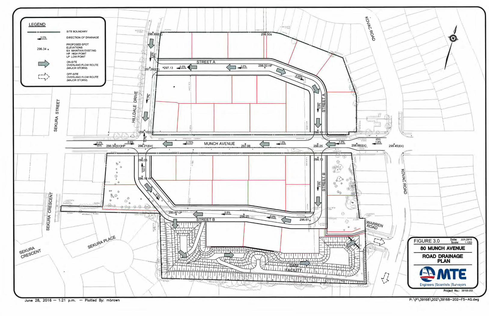
4.0 PROPOSED DEVELOPMENT AND SWM STRATEGY 4.1 Proposed Area Grading Proposed road grades and storm drainage flows are illustrated on Figure 3.0. The roads have a range in slope of 0.5% to 3%. The development will have a variety of lot types including back to front drainage and split drainage lots. The grading design of the site was controlled by many factors which include servicing constraints, matching existing grades along the adjacent properties and environmental features, as well as minimizing imported fill for the development. The major storm overland flow route for this development is along the road right-of-ways to the south central area of the site, through the SWM facility and towards the existing end of Warren Road.
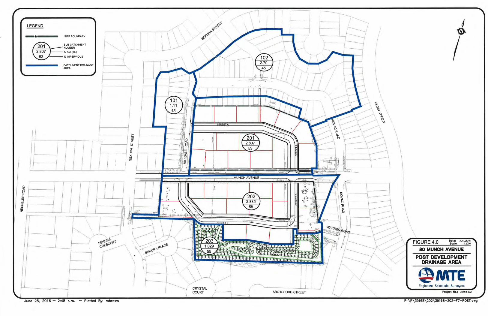
4.2 Post-Development Drainage Conditions
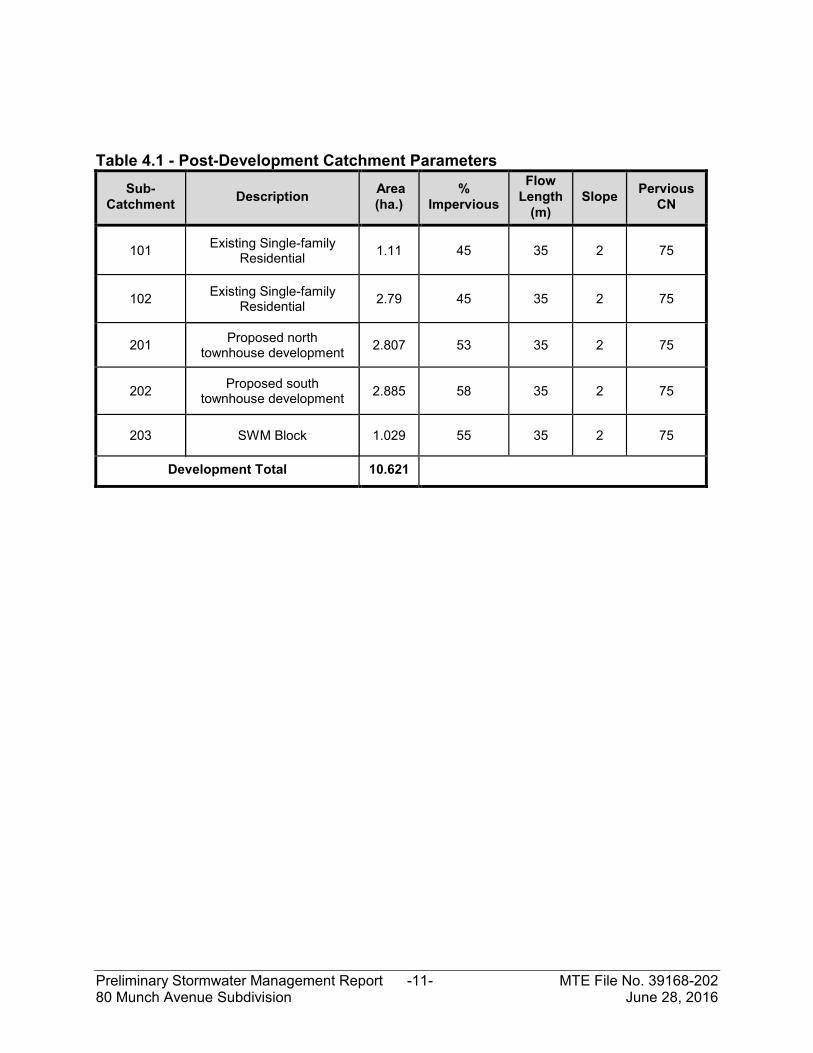
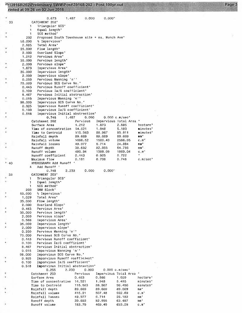
The development plans for the proposed SWM scheme includes approximately 5.85 ha of land. This land is comprised primarily of residential land use, townhouse units, and a stormwater management facility providing quality and quantity control. The SWM facility is designed to manage stormwater runoff from the entire proposed site (5.85 ha), external catchments (4.37 ha), as well as existing Munch Avenue. (0.40 ha), totaling 10.62 ha. Figure 4.0 provides an illustration of the post-development catchment areas. The SWM facility will attenuate storm events, from the 25 mm – 4 hour storm up to and including the 100 year storm event. All overland flow routes (i.e. road right-of-ways), discharge directly to the SWM facility. Major events enter the pond via a combination of piped flow and overland flow route, sized for the 100 year event. Table 4.1 provides a brief description of each sub-catchment area as well as the design parameters used in the hydrologic modeling.
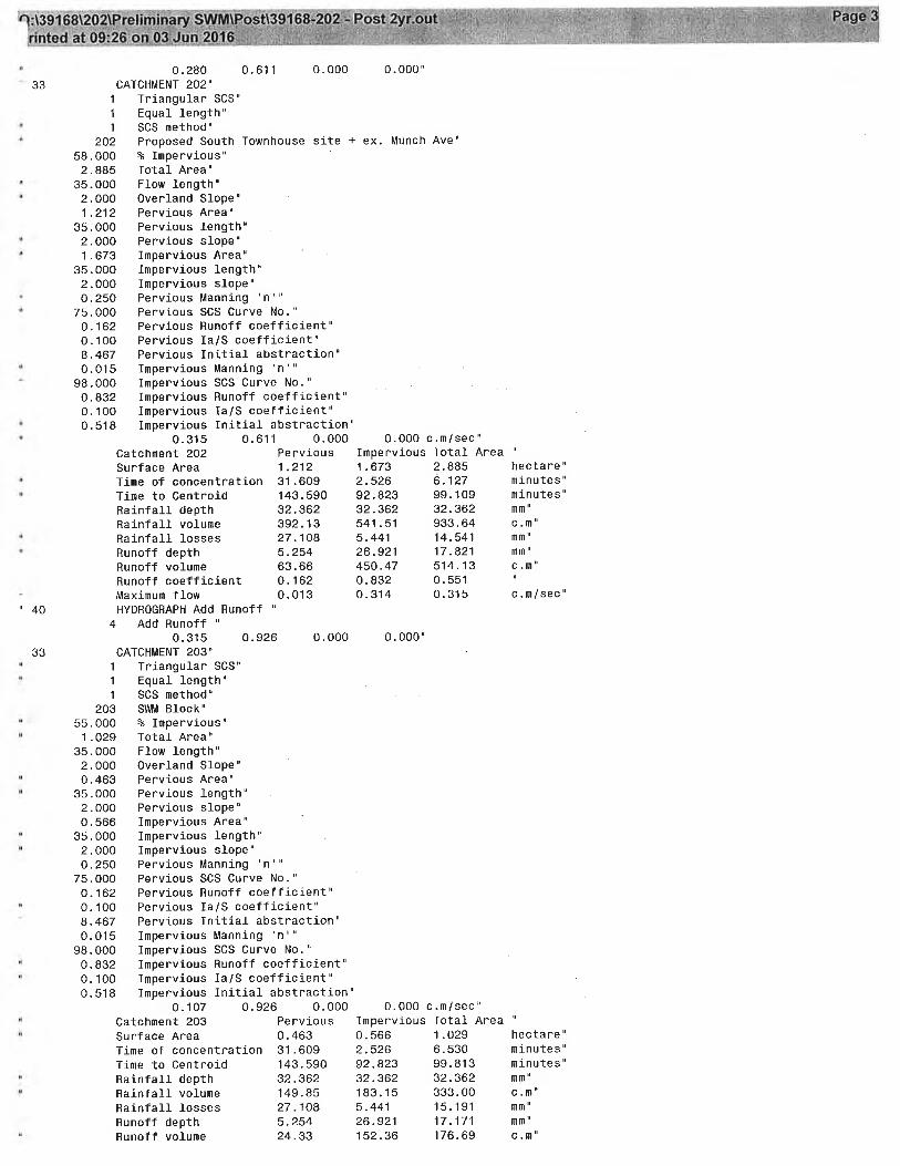
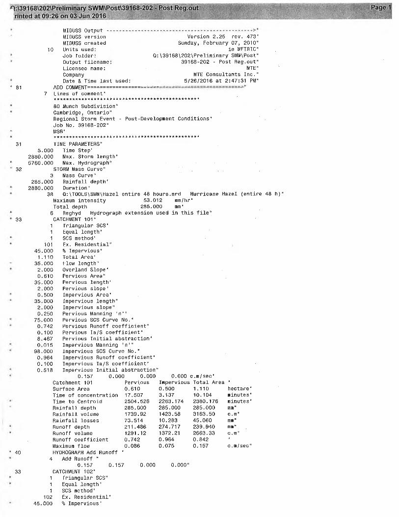
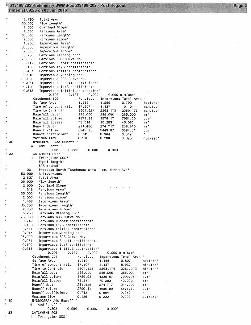
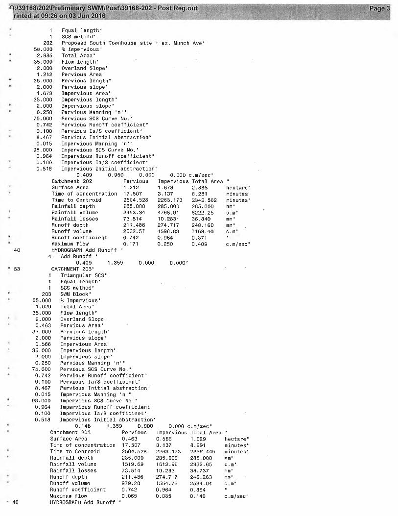
5.0 STORMWATER MANAGEMENT DESIGN 5.1 Hydrologic Modeling A hydrologic model was developed to simulate drainage conditions for the study area to provide a quantitative estimate of flows under existing and proposed development conditions. The MIDUSS hydrologic modeling program was utilized for the storm event simulations. Existing and proposed development conditions were modeled for the:
Quality event (25 mm depth, 4 hour Chicago distribution) 2 year, 5 year and 100 year return period rainfall events (3hr Chicago distribution
derived from the City of Cambridge Intensity-Duration-Frequency parameters)
Regional Storm event derived from the Region of Waterloo Intensity-Duration-Frequency parameters)
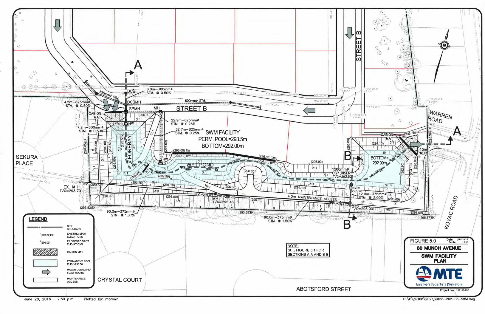
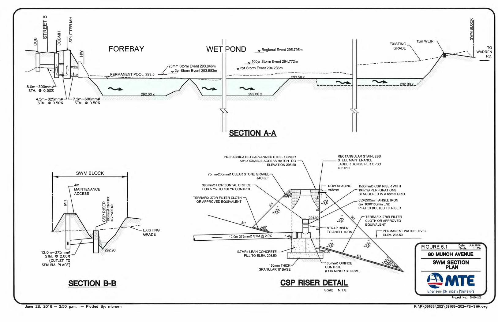
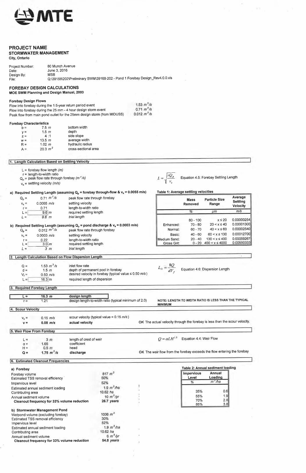
The hydrologic parameters for each of the pre- and post-development catchment areas are summarized in Table 2.1 and 4.1 respectively. The MIDUSS modeling output is provided in Appendix B. 5.2 Stormwater Quality Control The SWM facility has been designed as a wet pond with a permanent pool depth of 1.5m. The facility offers the benefits of dilution and settling of sediment within the forebay and the wet pond components. A planting scheme will be prepared that carefully selects plant species and their location in and around the basins to stabilize banks, mitigate temperature increases, deter waterfowl from nesting within the area, and provide aesthetics and safety benefits. The proposed SWM facility is divided into two cells. The first cell consists of a sediment forebay (quality control) that will accept minor storm event flows from the site via a major/minor storm control (splitter) structure, totaling 10.621 ha as shown on Figure 4.0. The second cell consists of the quantity control portion (wet pond/detention storage area) of the pond. Water quality control details are found in Table 5.1. Refer to Figures 5.0 and 5.1 for the plan views, sections and details of the SWM facility. Since the majority of annual rainfall occurs in storms less than or equal to a 25 mm event, the majority of water borne sediment is also transported to the SWM facility in these less intense events1. Therefore, the sediment forebays are designed targeting the smaller flows. Furthermore, since larger storm events will have greater peak flows, there is potential for re-suspension of accumulated sediment. Thus, the smaller flows into the forebay should be 1 From MOE-1994, Figure C.1: 62% less than 5mm, 78% < 10mm, 90% < 15mm and 97% < 25mm
separated from the larger flows which should enter the main pond directly. To achieve this objective, an appropriately sized splitter structure upstream of the stormwater management pond is proposed. Sizing of a splitter structure by simply sizing the outlet pipes based on their free flowing (Manning’s) capacities often results in ‘washout’ of the forebay (and costly remediation) due to larger flows that result from surcharging of the splitter structure. The design of the splitter structure for this project incorporates both free flowing pipe capacities (i.e. assuming no surcharge and using Manning’s equation) as well as the effects of head buildup within the splitter structure and associated discharge pipes The forebay design is based on classic particle settling and flow dispersion equations as presented in the MOE 2003 Stormwater Management Practices Planning and Design Manual. The methodology presented in that document suggests that the design flow for the forebay should be taken as the peak outflow from the facility. A forebay is typically designed to treat minor storm flows. Therefore, the main pond will essentially be empty (or at its permanent pool level) and there will be no mass of water at the outlet of the forebay that would control the flow through the forebay to the main pond’s discharge rate. This being the case, the design of the forebay should be based on the notion that the flow into the forebay equals the flow through the forebay, which equals the flow out of the forebay. In using this approach, the recommended settling velocity of 0.0003 m/s (from MOE 2003) results in extremely large and un-achievable forebay lengths. Therefore, the forebay is designed to satisfy the following four conditions:
Settling length based on a settling velocity of 0.0003 m/s using the main pond peak discharge for the 25 mm event (as per MOE 2003).
Settling length based on a settling velocity of 0.0055 m/s using the forebay
inflow/outflow for the 25mm event.
Dispersion length such that, based on flow and depth of water, the velocity through the forebay is less than 0.5 m/s.
Velocity based on flow divided by cross-sectional area is less than 0.15 m/s to
prevent scouring. The 2003 MOE document suggests that the clean-out frequency for the SWM facility be based on the sediment loading within the entire pond, however, it is recommended that the clean-out frequency be based on the loadings within the forebay only. While this typically results in more frequent clean-out, it is restricted to the forebay area only and avoids disturbance of the main pond. The clean-out frequency for the proposed SWM facilities can be found in the respective forebay design calculations in Appendix A. As previously mentioned, a Normal Level (formerly Level 2) of water quality protection is required. Quality control measures proposed for the SWM facility will take the form of a wet pond, servicing a drainage area imperviousness of 51.6%. An Normal Level of water quality control (based on a wet pond) requires a storage volume of 107 m3/ha for the above
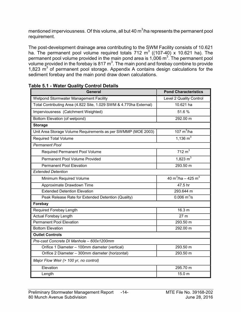
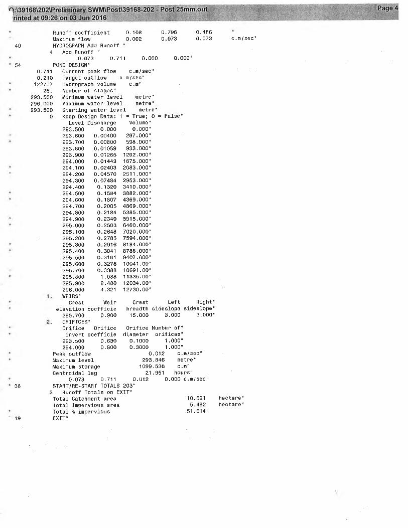
mentioned imperviousness. Of this volume, all but 40 m3/ha represents the permanent pool requirement. The post-development drainage area contributing to the SWM Facility consists of 10.621 ha. The permanent pool volume required totals 712 m3 ((107-40) x 10.621 ha). The permanent pool volume provided in the main pond area is 1,006 m3. The permanent pool volume provided in the forebay is 817 m3. The main pond and forebay combine to provide 1,823 m3 of permanent pool storage. Appendix A contains design calculations for the sediment forebay and the main pond draw down calculations. Table 5.1 - Water Quality Control Details
General Pond Characteristics Wetpond Stormwater Management Facility Level 2 Quality Control Total Contributing Area (4.822 Site, 1.029 SWM & 4.770ha External) 10.621 ha
Imperviousness (Catchment Weighted) 51.6 %
Bottom Elevation (of wetpond) 292.00 m Storage
Unit Area Storage Volume Requirements as per SWMMP (MOE 2003) 107 m3/ha
Required Total Volume 1,136 m3
Permanent Pool
Required Permanent Pool Volume 712 m3
Permanent Pool Volume Provided 1,823 m3
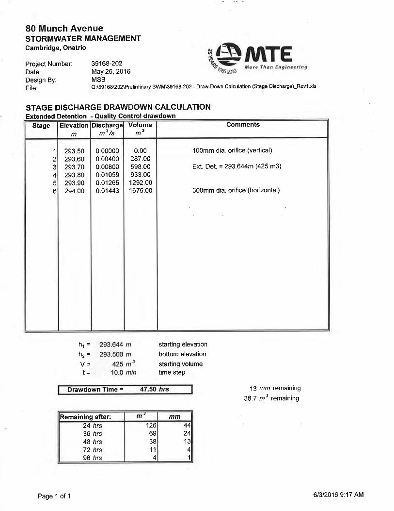
Permanent Pool Elevation 293.50 m Extended Detention
Minimum Required Volume 40 m3/ha – 425 m3
Approximate Drawdown Time 47.5 hr Extended Detention Elevation 293.644 m Peak Release Rate for Extended Detention (Quality) 0.006 m3/s
Forebay Required Forebay Length 16.3 m Actual Forebay Length 27 m Permanent Pool Elevation 293.50 m Bottom Elevation 292.00 m Outlet Controls Pre-cast Concrete DI Manhole – 600x1200mm
Orifice 1 Diameter – 100mm diameter (vertical) 293.50 m Orifice 2 Diameter – 300mm diameter (horizontal) 293.50 m
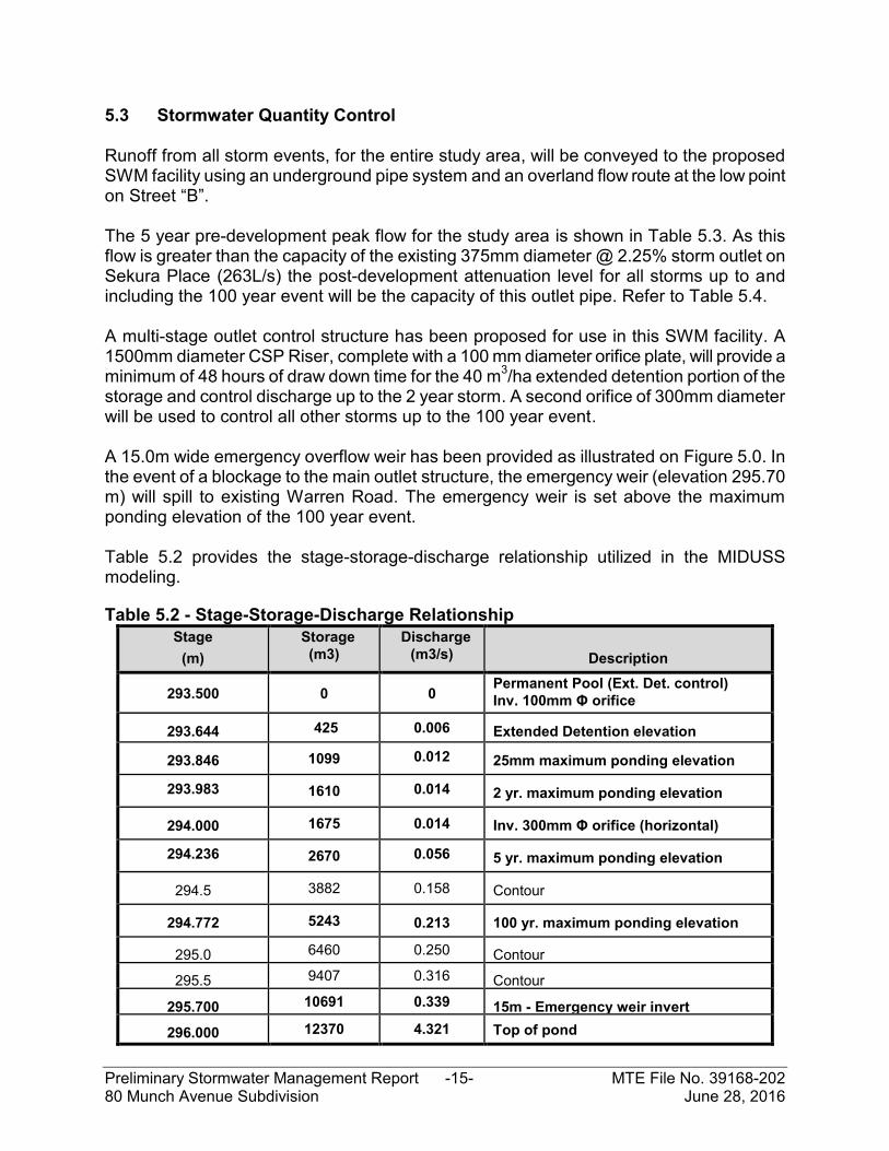
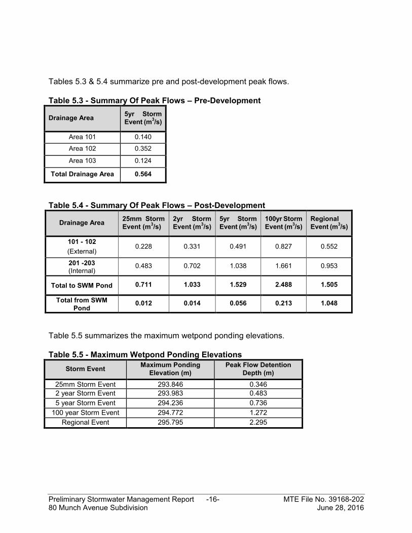
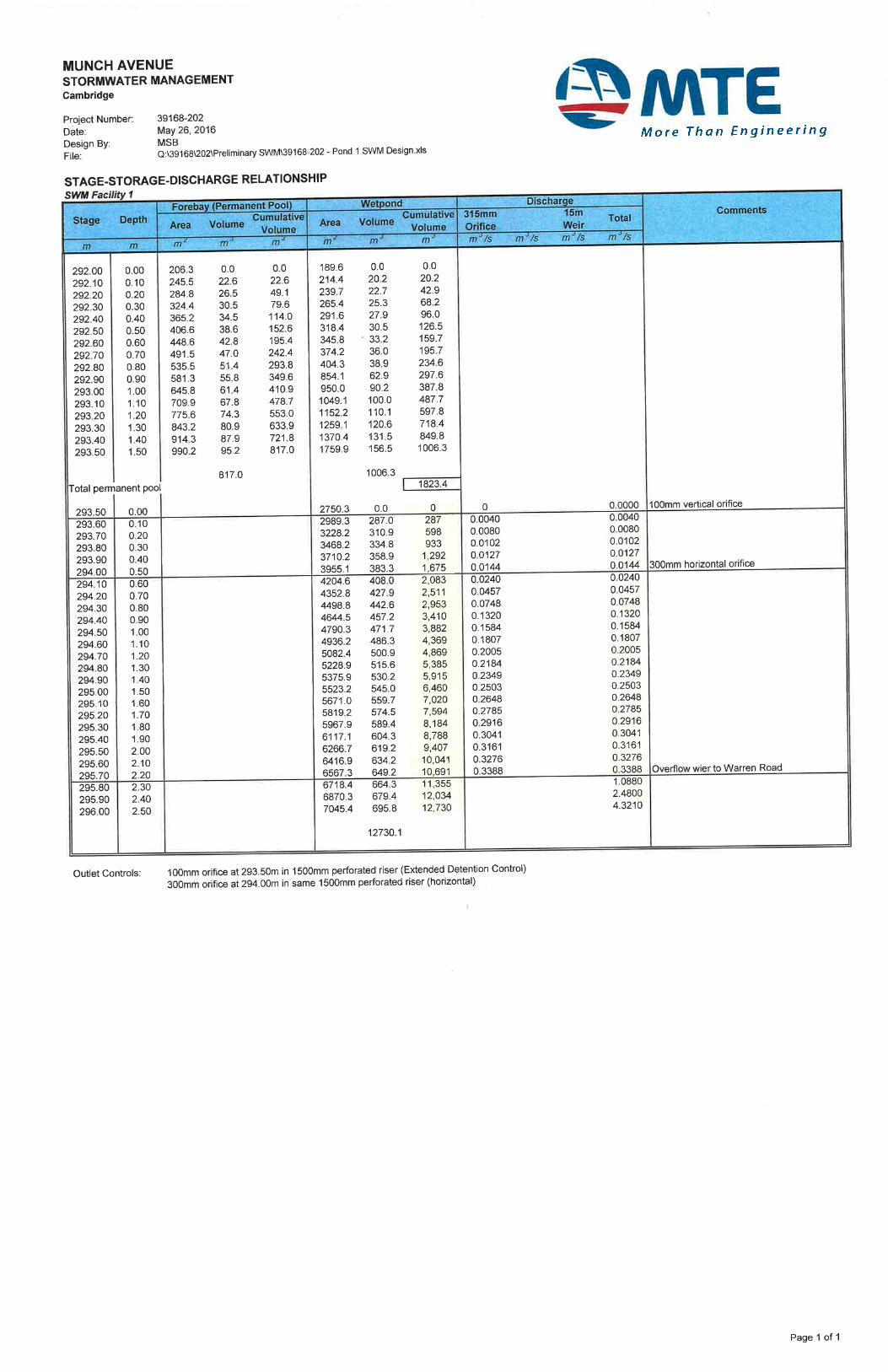
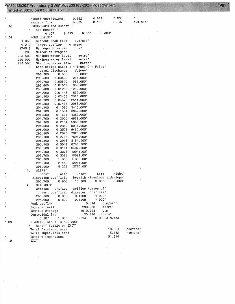
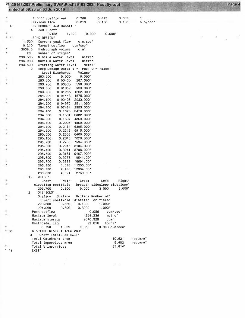
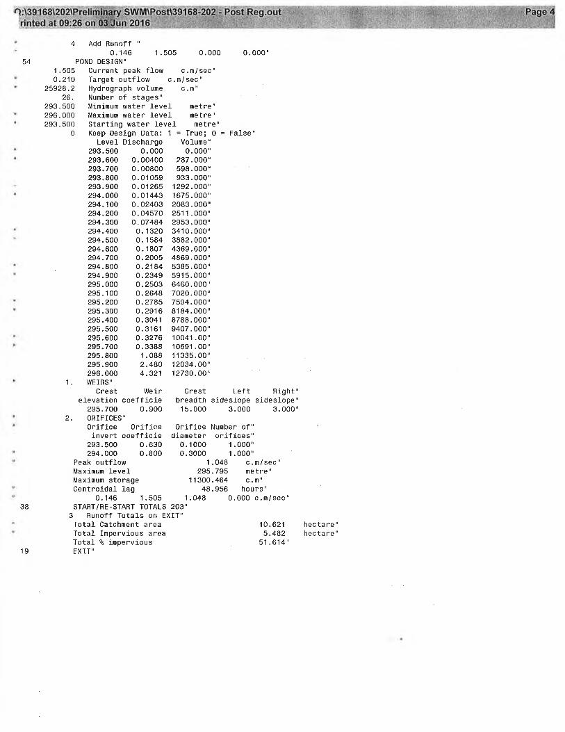
5.3 Stormwater Quantity Control Runoff from all storm events, for the entire study area, will be conveyed to the proposed SWM facility using an underground pipe system and an overland flow route at the low point on Street “B”. The 5 year pre-development peak flow for the study area is shown in Table 5.3. As this flow is greater than the capacity of the existing 375mm diameter @ 2.25% storm outlet on Sekura Place (263L/s) the post-development attenuation level for all storms up to and including the 100 year event will be the capacity of this outlet pipe. Refer to Table 5.4. A multi-stage outlet control structure has been proposed for use in this SWM facility. A 1500mm diameter CSP Riser, complete with a 100 mm diameter orifice plate, will provide a minimum of 48 hours of draw down time for the 40 m3/ha extended detention portion of the storage and control discharge up to the 2 year storm. A second orifice of 300mm diameter will be used to control all other storms up to the 100 year event. A 15.0m wide emergency overflow weir has been provided as illustrated on Figure 5.0. In the event of a blockage to the main outlet structure, the emergency weir (elevation 295.70 m) will spill to existing Warren Road. The emergency weir is set above the maximum ponding elevation of the 100 year event. Table 5.2 provides the stage-storage-discharge relationship utilized in the MIDUSS modeling. Table 5.2 - Stage-Storage-Discharge Relationship
5.4 Stormwater Management Facility The following list of SWM facility design characteristics, read in conjunction with the above drawings and figures, outlines all significant design aspects and rationales.
As previously described in Section 5.2 , the SWM facility has been designed as a wet pond facility with sufficient permanent and active storage volumes to achieve an Normal (formerly Level 2) degree of protection.
The outlet control structures for the SWM facility will be in the form of a CSP Riser
with a low flow orifice, and an emergency overflow weir. The outlet control orifice located on the CSP Riser has been designed to provide a minimum of 48 hours of drawdown time for the extended detention volume.
Access/maintenance roads of 4m width have been incorporated into the design of
the SWM facility to ensure sufficient access to the inlet and outlet structures and forebay for ease of inspection and maintenance. The access roads will have a maximum longitudinal slope of 10:1 and have a minimum inside radius of curvature not less than 9m.
5.5 Landscape Design A landscape design has not been completed for the SWM Facility at this time. A Landscape Plan will be provided at time of Final Design. The purpose of landscaping of these facilities is for aesthetics, erosion protection and long term stability of the banks and engineered slopes, and to limit pedestrian access into its permanent pool components. To that end, the facility will be designed in accordance to the City of Cambridge Stormwater Management Policies and Guidelines for aesthetics and safety of SWM facilities. The plant species recommended in the design will be taken only from those included in the Listing of Trees and Shrubs Native to The Regional Municipality of Waterloo, adopted by the Regional Municipality of Waterloo in 1993.
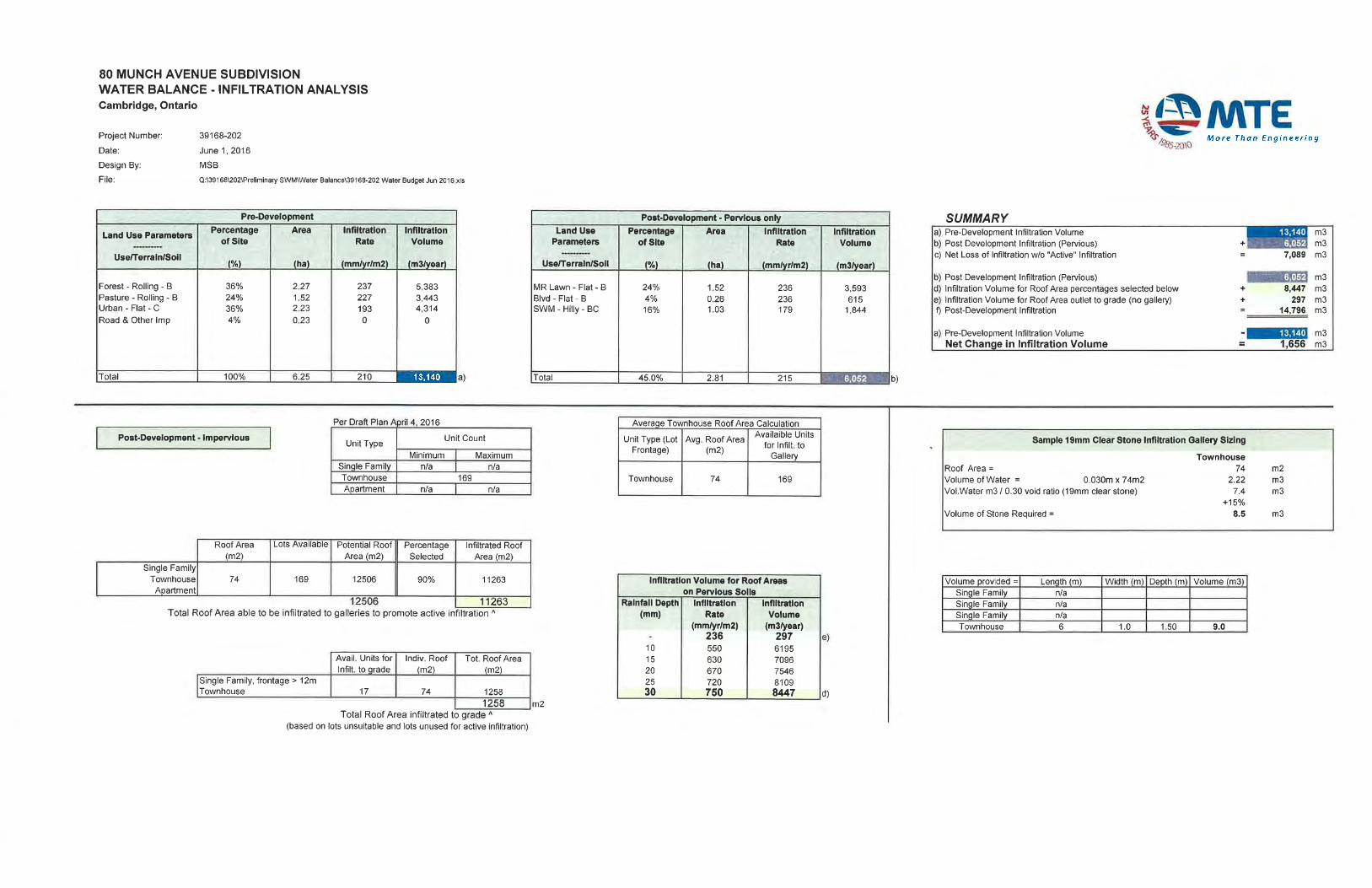
5.6 Water Budget - Infiltration An infiltration analysis was performed for the developable site area, including Munch Avenue (6.251 ha). The following methodology was followed in the development of the infiltration water balance:
1. Establish Evapotranspiration (ET) values for the Kitchener-Waterloo Region. 2. Determine hydrologic components (Evapotranspiration - ET, Runoff - R, Infiltration –
I) for different soil types (based on detailed soil investigation reports), vegetation cover, land use, etc.
3. Gather topographical information of catchments. 4. Gather hydrogeological and geological reports to determine soil distribution within
the catchments. 5. Establish hydrologic component values for each catchment.
The 1971-2000 average annual precipitation values from the Canadian Climate Normals are 957.8 mm and 907.9 mm at the Preston and Waterloo Wellington Airport locations, respectively. The average annual precipitation for the site was averaged at 932.9 mm/yr. The pre-development catchment discretization and analysis can be found in Appendix C. The site, under existing conditions, provides an annual infiltration volume of 13,140 m3. The development of the lands to a residential land use, with an impervious coverage of approximately 55%, would result in a reduction of the recharge volume to the groundwater system. This reduction results from impermeable surfaces such as houses, driveways and roads replacing the existing permeable surfaces. Calculations indicate that under post-development conditions, there will be an infiltration deficit of approximately 7,089 m3 per year with only ‘passive’ infiltration (infiltration through the remaining pervious surfaces). This deficit can be offset by infiltrating rooftop storm water runoff via infiltration galleries. See attached Infiltration Analysis in Appendix C. It is important to infiltrate as much water at source (passive infiltration on pervious areas and roof leaders to lot-level infiltration galleries) as possible to distribute infiltration across the site. The following summary outlines all significant design aspects and rationale with respect to the post-development condition and method by which the infiltration target will be approached.
Infiltration will occur “passively” within pervious areas on the site. “Active” infiltration of roof areas using lot-level infiltration galleries will be completed,
to capture and infiltrate roof runoff for storm events ≤ 30mm depth. Infiltration galleries must:
o be located in soils with a permeability rate >15 mm/hr, o maintain a groundwater separation of 1.0m, o respect structural and subdivision condition setbacks, o not be installed at the top of steep slopes (i.e. along the west slope),
All remaining roof areas (without lot-level infiltration galleries) will drain to grade for
additional infiltration.
All non-roof impervious areas (roads, driveways) will drain via the storm sewer network to the proposed SWM ponds. Additionally, any runoff from pervious areas or overflow from lot-level controls will also drain to the proposed SWM pond.
The infiltration analysis indicates that the ‘passive’ infiltration volume post-development is approximately 46% of the pre-development volume. By supplementing passive infiltration with the capture and infiltration of roof runoff, post-development infiltration volumes are brought above pre-development conditions. The total roof area proposed to be infiltrated is 1.13 ha. This total roof area represents; 152 units at 74 m2 of roof area per townhouse units. Along with additional infiltration of roof water discharged to grade (17 townhouse units), the result is a total active infiltration volume of approximately 8,744 m3 per year. Referring to the appended water balance calculations, which incorporate the assumptions noted above, annual infiltration is expected to exceed the target infiltration volume for the subject site by approximately 1,656 m3 per year.
6.0 MONITORING PROGRAM A monitoring program will be implemented which will serve to ensure that the stormwater management plan proposed within this report is implemented and performing at an acceptable level. 6.1 During Development Monitoring Program This stage will begin at the commencement of area grading of the subdivision and will continue until full build out of the subdivision. Monitoring of the stormwater management facility will include: Stormwater Management Facility
Standard inspection of vegetation, structures, and general operation of hydraulic controls (observations of drawdown) within the Stormwater Management facility. These inspections are to occur seasonally and typically after a significant rainfall event.
Regular inspection and maintenance of erosion and sediment control measures around and within the SWM facility.
Lot Level Infiltration Galleries Installation of lot level infiltration galleries will be supervised by a geotechnical
engineer.
Standard inspection and maintenance of the SWM facility will be provided throughout the ‘During Development” period.
6.2 Post Development Monitoring Program This period of the monitoring will begin following full build out of the subdivision (ie. houses are constructed, lots are sodded, open spaces are stabilized). The purpose of this stage of the monitoring is to ensure that the SWM facility continues to operate as designed. Monitoring during this stage will include: Stormwater Management Facility
Standard inspection of vegetation, structures, and general operation of hydraulic controls (observations of drawdown) within the Stormwater Management facility. These inspections are to occur seasonally and typically after a significant rainfall event until assumption of the facility by the City.
It is recommended, that following completion of the developer’s portion of the post-development monitoring program and assumption of the SWM facility by the City, that the City continues with a post-development inspection and maintenance program to ensure the long term effectiveness of the proposed SWM facility.
7.0 EROSION AND SEDIMENT CONTROL MEASURES Precautions will be taken during construction to limit erosion and sedimentation. The erosion and sediment control plans have followed the Erosion & Sediment Control Guideline for Urban Construction document and have been included in this report. The plans will illustrate the erosion and sediment control measures to be implemented during construction, which will limit impacts associated with site development. Typically, the recommended construction sequence for erosion and sediment control measures will be as follows:
Placement of all sediment control fencing where required; Construction of permanent and temporary stormwater management ponds which
will serve as sedimentation basins for the site during construction;
Construction of temporary swales to direct runoff to sedimentation basins, with rock check dams as required to control velocities;
Stripping and strategic placement of topsoil stockpiles. Placement of sediment
control fencing around all stockpile areas; and
Re-vegetation of completed areas as soon as possible after construction, including those areas not slated for construction within 60 days.
Where rock check dams are proposed to promote sedimentation and reduce velocities, clean aggregate is to be placed perpendicular to the direction of flow in the swale, with a small volume of excavation on the upstream side to provide storage for accumulated sediment. Sediment control fencing shall consist of filter fabric attached to paige wire fencing and sealed at ground level. It will be installed at the perimeter of the work areas and intermittently on sloped areas where required. Sediment control fencing will be placed around all topsoil stockpiles. Storage consistent with the GRCA’s requirement of 125 m3/ha of live and dead storage respectively (total 250 m3/ha), will be provided. This storage will be provided to ensure that suspended material will have ample time to settle out. In addition, the sediment basin will be sized with sufficient capacity to allow flows to pass without breaching. Once the active construction and grading activities have been completed, the sedimentation basins can be cleaned out. Access to topsoil or fill storage areas will be located on the upstream side of storage piles. This practice will ensure continuity of the sediment control fencing in the downslope direction which is most vulnerable to erosion and sediment deposition. Further, topsoil and hydroseed will be placed on all exposed areas following the completion of grading activities.
8.0 CONCLUSIONS AND RECOMMENDATIOSN Based on the foregoing analyses, it is concluded that: 1. The minor drainage outlet for the 80 Munch Avenue Subdivision is the Grand River,
via an extended detention wetpond SWM facility and outlet pipe to existing storm sewers on Sekura Place. The major drainage outlet is to Mill Creek via overland flow commencing at Warren Road.
2. Adequate storage and discharge control can be established on-site to reduce the 5
year post-development peak flows to the SWM criteria as described in Section 3.1 of this report.
3. Adequate quality control protection (Normal Level) will be provided for stormwater
runoff from the site.
4. Infiltration targets can be satisfactorily met by directing roof water to lot-level infiltration galleries.
5. Erosion and sediment controls will minimize negative impacts of construction activities
on the receiving watercourse. The findings of this report, and the above conclusions, lead to the following recommendations: 1. That an extended detention wetpond facility be constructed to provide quality and
quantity control of stormwater for the 80 Munch Avenue Subdivision as described in Sections 4 and 5 of this report.
2. That all lot-level infiltration galleries be installed with overflows to the storm sewer
system within the subject site.
3. That where possible, roof water be directed to infiltration galleries as described in Section 5.6 of this report.
4. That during the site grading operations, soils be selectively excavated and placed,
under the supervision of a geotechnical engineer, in order to maximize the post-development areas suitable for infiltration.
5. That erosion and sediment controls be implemented prior to construction as described in Section of 6 of this report.
6. That the construction of the berm surrounding the SWM facility and controlling the
groundwater seepage in the north slope of the SWM Block be constructed under the supervision of a qualified geotechnical engineer.