Preliminary Validation of Fluid-Structure InteractionModeling for Hypersonic Deployable Re-Entry Systems
P. Pasolini1,2, R. Savino1, F. Franco1, S. De Rosa1
Abstract: The aim of the present work is to provide a first attempt to set anaero-thermo-elastic methodology for deployable atmospheric re-entry deceleratorsoperating at high Mach number and high dynamic pressure. Because of the severityof re-entry conditions such as high temperatures, high pressures and high veloci-ties, the behavior of their flexible structures is a hard target to assess. In this paper apartitioned Fluid Structure Interaction (FSI) approach based on the integration of d-ifferent commercial software (STAR-CCM+ and ABAQUS) is presented. In orderto validate the specific codes and the overall strategy for structural and fluid dy-namics analyses of flexible structures, different test cases are considered, includingnumerical and experimental literature results related to the problem under investi-gation. The paper shows that a good description of the physical behavior is possiblewith the proposed FSI partitioned approach. The model is preliminarily applied toinvestigate structural, fluid dynamic and aero-thermal behavior of a flexible deploy-able umbrella-like configuration along a typical suborbital re-entry trajectory basedon sounding rocket.
The idea to build structures with deployable Thermal Protection System (TPS) foratmospheric re-entry goes back to the 1960s. Only recently, interest in these typesof structures have received a strong thrust because several space missions, requiringentry in different planets atmospheres, including Earth, Mars, Titan, and Neptune[Smith, Tanner, Mahzari, Clark, Braun, and Cheatwood (2010)].
A structure, in which the TPS can be easily accommodated in launch vehicles in
1 Department of Industrial Engineering (DII), University of Naples “Federico II”, Via Claudio 21,80125 Napoli, Italy.
a folded configuration, and deployed only during re-entry phase, offers the advan-tage to increase the mass/volume ratio at launch, thereby providing easy payloadaccommodation in the launcher fairing. When deployed, the ballistic coefficient isrelatively low, implying a large deceleration in the upper rarefied region of the at-mosphere, with consequent reduction of the thermal and dynamic loads. The abovementioned ballistic coefficient is defined by the ratio between mass and the productof exposed surface times the drag coefficient.
Recent studies have been focused on Hypersonic Inflatable Aerodynamic Decel-erator (HIAD) technology [Beck, Arnold, White, Fan, Stackpoole, Agrawal, andCoughlin (2011); Sheta, Venugopalan, Tan, Liever, and Habchi (2010); Cassell,Swanson, Keith Johnson, Hughes, and Cheatwood (2011)]. One example is theInflatable Re-entry and Descent Technology (IRDT) [Wilde and Walther (2001)].The most advanced program, including experimental flight test and aero-elastic as-sessments, is the Inflatable Re-entry Vehicle Experiment (IRVE) [Harper and Braun(2014); Hughes, Dillman, Starr, Stephan, Lindell, Player, and Cheatwood (2005);Litton, Bose, Cheatwood, Hughes, Wright, Lindell, Derry, and Olds (2011); Hugh-es, Cheatwood, Dillman, Wright, Del Corso, and Calomino (2011); Wang, Yang,Liu, Wang, Mignolet, and Bartels (2010); Kramer, Cirak and Pantano (2013); Gold-man and Dowell (2015); Goldman, Dowell and Scott (2015); Goldman, Scott andDowell (2014)]. Beside those, only few concepts for mechanically deployable at-mospheric re-entry systems exist. One of the first concepts was a deployable cap-sule, developed by Akin (1990), using an umbrella-like heat shield, made of siliconfabrics, called Parashield.
The University of Naples “Federico II” is currently working in cooperation withother small and medium enterprises, on the development of a Hypersonic Deploy-able Aerodynamic Decelerator (HDAD) [Iacovazzo, Carandente, Savino and Zup-pardi (2015); Carandente and Savino (2014); Carandente, Zuppardi and Savino(2014); Carandente, Savino, Iacovazzo and Bozza (2013); Carandente, Elia andSavino (2013); Savino and Carandente (2012)]. This research program, coordinat-ed by the Italian and European Space Agencies, has the purpose to demonstratethe possibility to develop, in the near future, a low-cost deployable re-entry cap-sule to enable future space missions, including payloads return on Earth from theISS and/or recoverable scientific experiments in Low Earth Orbit (LEO) [Caran-dente, Savino, D’Oriano and Fortezza (2014); Bassano, Savino, Lo Forti, Fer-rarotti, Richiello, Russo, Aurigemma, Punzo, and Dell’Aversana (2011); Savino,Aurigemma, Carandente, Dell’Aversana, Gramiccia, Longo, Marraffa, and Punzo(2013)].
The characterization of the Aero-Thermo-Elastic (ATE) behavior of a flexible struc-ture during atmospheric re-entry is obviously a Fluid-Structure-Interaction (FSI)
Preliminary Validation of Fluid-Structure Interaction Modeling 303
problem. The deflection of the flexible TPS subjected to aerodynamic and thermalloads influence the flow field, modifying in turn thermal and aerodynamic behavior.If this loop of influences results in an energy extraction from the flow stream, thestructure may experience flutter, resulting in a self-oscillation of the structure, andin eventual failure.
The purpose of the present work is to set up and validate a computational methodol-ogy by proper integration of commercial codes in order to assess ATE phenomenain the pre-design study phase of a HDAD. The article is organized as follows. InSection 2 a partitioned FSI approach using commercial codes, ABAQUS for thestructural analysis and Cd-Adapco STAR-CCM+ for the fluid dynamic analysis, isintroduced and described. A brief description of the capsule configuration is alsopresented in the aforementioned section. The approach validation is proposed inSection 3, where two different test cases are considered for the thermal-structuralinteraction and for the aero-thermal interaction. The model is preliminarily appliedto investigate the aero-thermal behavior of a flexible deployable umbrella-like con-figuration along a typical suborbital reentry trajectory in Section 4. Main resultsand conclusions are summarized in Section 5.
2 FSI Modeling approach
As mentioned in the introduction, analysis of re-entry conditions for non-liftingcapsules with deployable TPS includes aero-thermo-elastic studies to predict thedynamic behavior of the flexible heat shield. The conditions that the capsule ex-periences during re-entry, in particular high dynamic pressure, high temperaturesand high heat fluxes with consequent large deformation of the flexible structures re-quires an in depth analysis of the interaction between the fluid and structure. Figure1 shows the accuracy level required from each subject of the hypersonic Aerother-moelasticity of flexible structures.
Computational Aero-Thermo-Elasticity (CATE) generally refers to coupling high-level computational fluid dynamic (CFD) solvers with high-level structural dynam-ic solvers (generally using FEA approach). Mc Namara and Friedman (2007),(2011), and Culler and McNamara (2010) have studied a CATE methodology incor-porating heat transfer between fluid and structure using CFD-based aerodynamicheating computations.
For this type of analysis, the aerodynamic heating conditions were obtained fromthe CFD solver, and have been exchanged to the FEM solver that computes thethermal deflections. In his studies, Mc Namara has highlighted two categories offluid–structural coupling namely, monolithic and partitioned. For the monolithicapproach, the governing equations of the fluid and structure are combined into a
consistent scheme and marched forward in time simultaneously. In a partitionedapproach, the fluid model and the structural model are solved using separate CFDand computational structural dynamic solvers, coupled at the interface by a thirdsolver. Using a monolithic approach consistent time advancement provides a rela-tively high accuracy, but the solution requires efforts due to different mathematicalproperties of the governing equations. On the other hand, a partitioned approachprovides flexibility to use different convenient solvers for the fluid and structuralproblems. Therefore, the governing equation are solved using the most suitablenumerical schemes and the most advanced solvers for each problem.
Figure 1: Fluid-Structure-Thermal Interaction Solutions using ComputationalStructural Dynamic Computational Thermo-Dynamic, and Computational FluidDynamic analysis methods.
In this paper, a partitioned approach has been considered (Figure 2), using commer-cial software, respectively ABAQUS v6.13 to solve the structural problem and Cd-Adapco STAR-CCM+ v10.02 to solve the aero-thermo-dynamic flow field. Howev-er, there are two complex tasks that a partitioned approach must fulfill: 1) projectionof loads/deformation between each solver; and 2) time advancement. In the presentwork, coupling between the fluid and the structural domain has been assigned tothe SIMULIA Co-Simulation Engine (CSE) solver implemented in the last versionof the Cd-Adapco STAR-CCM+ 10.02 CFD solver.
The numerical methodology must be validated to perform accurate ATE analysis.
Preliminary Validation of Fluid-Structure Interaction Modeling 305
Figure 2: Basic structure of the aero-thermo-elastic problem when solved usingcoupled CFD and CTSD solvers [Mc Namara and Friedmann (2007)]
In this work, we have selected as a reference configuration the capsule with a flex-ible TPS in umbrella-like configuration presented by Iacovazzo, Carandente, Savi-no and Zuppardi (2015); such configuration is presented in Figure 3. The relevantflight characteristics have been evaluated by Iacovazzo, Carandente, Savino andZuppardi (2015) for this deployable capsule along a typical suborbital re-entry tra-jectory based on sounding rocket launch. In particular, two flight conditions of thetrajectory computed in aforementioned work have been considered, correspondingto the maximum heat flux and the maximum stagnation point pressure (Table 1).
Figure 3: Schematic configuration for a re-entry demonstrator to be testes on boardREXUS rocket (half cone angle 45◦) [Iacovazzo, Carandente, Savino and Zuppardi(2015)]
Suitable test cases have been selected to perform preliminary structural, fluid dy-namic and aero-thermo-dynamic analyses using the commercial software ABAQUSfor the structural domain and Cd-Adapco STAR CCM+ for the fluid domain.
3 Model Validation
As highlighted by Bisplinghoff and Dugundji (1958), in order to discuss the ATEproblem, it is useful to extend the Collar’s triangle to a rectangle (Figure 4). In gen-eral, there are various degrees of coupling among all the rectangle elements. Forexample, the aero-thermo-elastic coupling is conceivable if the aero-thermal char-acteristic time (given by the ratio between the square of the characteristic lengthand the thermal diffusivity of the material) is comparable to the aero-elastic char-acteristic time (given by the ratio between one to natural frequency of the structure).
Figure 4: Aero-thermo-elastic rectangle [Bisplinghoff and Dugundji (1958)]
In order to validate a complete methodology for the coupling between all elementsof the rectangle proposed by Bisplinghoff, for this preliminary work, it has beenchosen to uncouple the ATE problem in two sub-coupling interaction problemswith the thermal influence at center: 1) The Thermo-Structural Interaction; 2) TheAero-Thermal Interaction. Two benchmark experiments available in literature havebeen selected to compare the results of the present work.
Preliminary Validation of Fluid-Structure Interaction Modeling 307
3.1 Thermo-Structural Interaction
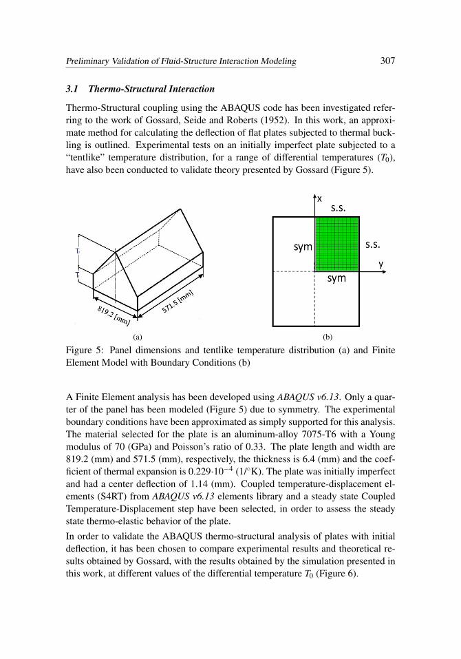
Thermo-Structural coupling using the ABAQUS code has been investigated refer-ring to the work of Gossard, Seide and Roberts (1952). In this work, an approxi-mate method for calculating the deflection of flat plates subjected to thermal buck-ling is outlined. Experimental tests on an initially imperfect plate subjected to a“tentlike” temperature distribution, for a range of differential temperatures (T0),have also been conducted to validate theory presented by Gossard (Figure 5).
(a) (b)
Figure 5: Panel dimensions and tentlike temperature distribution (a) and FiniteElement Model with Boundary Conditions (b)
A Finite Element analysis has been developed using ABAQUS v6.13. Only a quar-ter of the panel has been modeled (Figure 5) due to symmetry. The experimentalboundary conditions have been approximated as simply supported for this analysis.The material selected for the plate is an aluminum-alloy 7075-T6 with a Youngmodulus of 70 (GPa) and Poisson’s ratio of 0.33. The plate length and width are819.2 (mm) and 571.5 (mm), respectively, the thickness is 6.4 (mm) and the coef-ficient of thermal expansion is 0.229·10−4 (1/◦K). The plate was initially imperfectand had a center deflection of 1.14 (mm). Coupled temperature-displacement el-ements (S4RT) from ABAQUS v6.13 elements library and a steady state CoupledTemperature-Displacement step have been selected, in order to assess the steadystate thermo-elastic behavior of the plate.
In order to validate the ABAQUS thermo-structural analysis of plates with initialdeflection, it has been chosen to compare experimental results and theoretical re-sults obtained by Gossard, with the results obtained by the simulation presented inthis work, at different values of the differential temperature T0 (Figure 6).
For the worst case of a differential temperature of 339 (K), a comparison betweenexperimental and numerical central lines shape is presented (Figure 7).
3.2 Aero-Thermal Interaction
The Aero-Thermal Interaction has been investigated considering the work car-ried out at NASA Langley Research center [Del Corso, Bruce, Liles, and Hugh-es (2011); Glass and Hunt (1988); Hughes, Ware, Del Corso, and Lugo (2009);Deveikis and Hunt (1973); and Del Corso, Bruce, Liles and Hughes (2011)]. Theaim of this work is to test several candidate materials for the TPS of the IRVE-3experiment program for the severe thermal conditions experienced by the flexibleTPS along a planetary entry trajectory.
The experimental tests have been conducted in the 8’ Foot High Temperature com-bustion heated, hypersonic blowdown wind tunnel. The duration of the test is ap-proximatively 90 sec. A dual wedge sled was mounted in the wind gallery so thattwo test conditions could be run simultaneously (Figure 8).
The low-pressure conditions presented by Hughes, Ware, Del Corso, and Lugo(2009) at a sled angle of 5◦ have been selected (Table 2). A comparison betweenCFD results of the NASA’s work conducted with Vulcan v6.0.1 CFD code, andCFD results conducted with Cd-Adapco STAR-CCM+ v10.02 CFD code is sum-marized in Table 3.
Aero-thermal coupling has been simulated using two commercial codes, ABAQUSfor the material thermal distribution, and STAR-CCM+ to solve flow motion equa-tions and aerodynamic heating conditions. For the structural model an uncoupledheat transfer implicit scheme has been used, in which the temperature field is cal-culated without considering the stress/deformation study. Diffusive heat transfer
Preliminary Validation of Fluid-Structure Interaction Modeling 309
(a)
(b)
Figure 7: Comparison between transverse center line (a) and longitudinal centerline (b) displacements.
Figure 8: Sketch of the test sled [Hughes, Ware, Del Corso, and Lugo (2009)].
elements (DC3D8), have been selected from ABAQUS elements library to simu-late the thermal conduction inside the texture. The flow field is turbulent and thenumerical simulations have been performed with a K-Epsilon 3D, time implicit
numerical scheme. The SIMULIA Co-Simulation Engine solver has been used toexchange data between the two model interfaces. An implicit staggered algorithmwith a time step of 0.5 seconds has been used to interchange heat transfer coeffi-cients and temperature values between codes. As benchmark sample, we selectedthe layup 6 (Figure 9) placed in a forward location and the low-pressure flow con-dition due to the good nominal results obtained by experimental tests. The topsurface of the layup 6 structural model has been coupled with the relative wall ofthe CFD domain according to the dimensions reported by Del Corso, Bruce, Lilesand Hughes (2011); only a section of the wind tunnel has been modeled (Figure10). The layup 6 is a Coupon TPS made of four layers. The Refrasil C1554-48outer fabric layer is exposed directly to the Mach 7 flow in the 8’HTT. The Pyrogel6650 insulator fabric is used to prevent excessive heating through the thickness.The Kapton fabric is intended to act as a gas barrier between the aero-shell bladderand the aero-shell TPS. All layers material properties are summarized in Table 4.As evaluated by Del Corso, Bruce, Liles, and Hughes (2011), a contact resistanceof 18 (m2K/W) has been introduced to simulate the gap among texture layers.
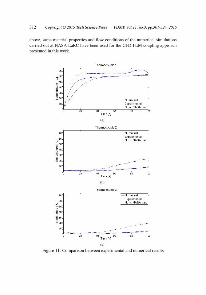
A comparison between experimental results, aero-thermal interaction simulationmethodology presented in this work, and numerical simulation results presentedby Hughes, Ware, Del Corso, and Lugo (2009) is depicted in Figure 11. It shouldbe noted that there is good agreement between the experimental test and the aero-
Preliminary Validation of Fluid-Structure Interaction Modeling 311
Table 4: Layup 6 material properties [Hughes, Ware, Del Corso, and Lugo (2009)]
Material LayerType
Thickness(mm)
Density(Kg/m3)
Conductivity(W/m·K)
SpecificHeat
(J/Kg·K)Emissivity
RefrasilC1554-48 Outer 0.66 924 0.865 1172 0.7
Pyrogel6650 Insulator 6.35 110
0.01 at 0◦C0.02 at 130◦C0.03 at 480◦C
1046 -
Kapton Barrier 0.03 1468 0.12 1022 -
Figure 9: TPS coupon layup 6 and thermocouple locations
Figure 10: CFD and FEM coupling models
thermal interaction simulation. The simulation results report an average value be-tween top and bottom node temperatures of each couple of layers. As highlighted
above, same material properties and flow conditions of the numerical simulationscarried out at NASA LaRC have been used for the CFD-FEM coupling approachpresented in this work.
(a)
(b)
(c)
Figure 11: Comparison between experimental and numerical results
Preliminary Validation of Fluid-Structure Interaction Modeling 313
4 Preliminary uncoupled ATE analysis of deployable re-entry capsule
4.1 Fluid Dynamic Model
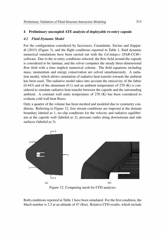
For the configuration considered by Iacovazzo, Carandente, Savino and Zuppar-di (2015) (Figure 3), and the flight conditions reported in Table 1, fluid dynamicnumerical simulations have been carried out with the Cd-Adapco STAR-CCM+software. Due to the re-entry conditions selected, the flow field around the capsuleis considered to be laminar, and the solver computes the steady three-dimensionalflow field with a time implicit numerical scheme. The field equations includingmass, momentum and energy conservation are solved simultaneously. A radia-tion model, which allows simulation of radiative heat transfer towards the ambienthas been used. The radiative model takes into account the emissivity of the fabric(0.443) and of the aluminum (0.1) and an ambient temperature of 270 (K) is con-sidered to simulate radiative heat transfer between the capsule and the surroundingambient. A constant wall static temperature of 270 (K) has been considered toevaluate cold wall heat fluxes.
Only a quarter of the volume has been meshed and modeled due to symmetry con-ditions. Referring to Figure 12, free stream conditions are imposed at the domainboundary labeled as 1, no-slip conditions for the velocity and radiative equilibri-um at the capsule wall (labeled as 2), pressure outlet along downstream and sidesurfaces (labeled as 3).
(a) (b)
Figure 12: Computing mesh for CFD analyses
Both conditions reported in Table 1 have been simulated. For the first condition, theMach number is 2.5 at an altitude of 47 (Km). Relative CFD results, which include
Table 5: CFD resultsH (Km) M q̇qq0(kW/m2) p0 (kPa)
Max HeatFlux condition 47 2.5 6.7 0.95
Max stagnationpoint pressure
condition40 1.7 2.4 1.15
Mach number, pressure, and surface boundary heat flux, are summarized in Figure13. Since radiative heat fluxes are not so relevant compared to the convective heatfluxes, because of the cold wall boundary condition imposed in the simulation, onlyconvective heat flux is depicted.
(a) (b)
(c)
Figure 13: Maximum heat flux condition CFD Results
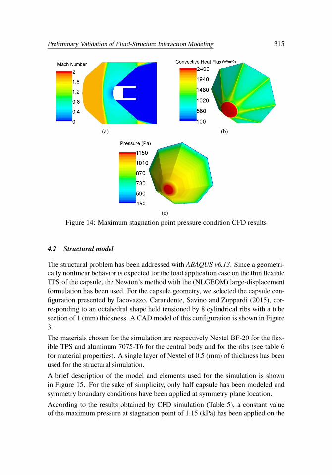
For the case corresponding to max stagnation point pressure condition along theentry trajectory illustrated in Table 1, main results are shown in Figure 14. Valuesof heat flux and stagnation point pressure, computed with the above mentionedconditions, are summarized in Table 5.
Preliminary Validation of Fluid-Structure Interaction Modeling 315
(a) (b)
(c)
Figure 14: Maximum stagnation point pressure condition CFD results
4.2 Structural model
The structural problem has been addressed with ABAQUS v6.13. Since a geometri-cally nonlinear behavior is expected for the load application case on the thin flexibleTPS of the capsule, the Newton’s method with the (NLGEOM) large-displacementformulation has been used. For the capsule geometry, we selected the capsule con-figuration presented by Iacovazzo, Carandente, Savino and Zuppardi (2015), cor-responding to an octahedral shape held tensioned by 8 cylindrical ribs with a tubesection of 1 (mm) thickness. A CAD model of this configuration is shown in Figure3.
The materials chosen for the simulation are respectively Nextel BF-20 for the flex-ible TPS and aluminum 7075-T6 for the central body and for the ribs (see table 6for material properties). A single layer of Nextel of 0.5 (mm) of thickness has beenused for the structural simulation.
A brief description of the model and elements used for the simulation is shownin Figure 15. For the sake of simplicity, only half capsule has been modeled andsymmetry boundary conditions have been applied at symmetry plane location.
According to the results obtained by CFD simulation (Table 5), a constant valueof the maximum pressure at stagnation point of 1.15 (kPa) has been applied on the
texture. This has been done in order to evaluate the TPS static deflection at the max-imum stagnation point pressure condition along the flight re-entry trajectory basedon the supersonic sounding rocket (REXUS) considered by Iacovazzo, Carandente,Savino and Zuppardi (2015).
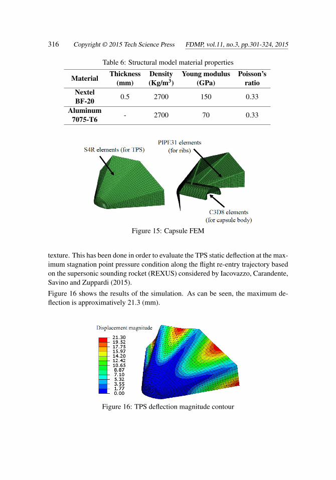
Figure 16 shows the results of the simulation. As can be seen, the maximum de-flection is approximatively 21.3 (mm).
Figure 16: TPS deflection magnitude contour
Preliminary Validation of Fluid-Structure Interaction Modeling 317
Table 7: Capsule thermal materials properties
Material Thickness(mm)
Density(Kg/m3)
Conductivity(W/m·K)
Specific Heat(J/Kg·K) Emissivity
Nextel440-BF20 0.5 2700 0.15 1100 0.443
AluminumAlloy 7075-T6 - 2700 237 880 0.1
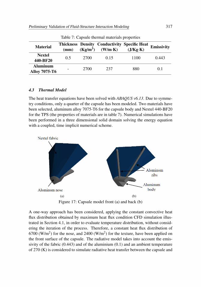
4.3 Thermal Model
The heat transfer equations have been solved with ABAQUS v6.13. Due to symme-try conditions, only a quarter of the capsule has been modeled. Two materials havebeen selected, aluminum alloy 7075-T6 for the capsule body and Nextel 440-BF20for the TPS (the properties of materials are in table 7). Numerical simulations havebeen performed in a three dimensional solid domain solving the energy equationwith a coupled, time implicit numerical scheme.
(a) (b)
Figure 17: Capsule model front (a) and back (b)
A one-way approach has been considered, applying the constant convective heatflux distribution obtained by maximum heat flux condition CFD simulation illus-trated in Section 4.1, in order to evaluate temperature distribution, without consid-ering the iteration of the process. Therefore, a constant heat flux distribution of6700 (W/m2) for the nose, and 2400 (W/m2) for the texture, have been applied onthe front surface of the capsule. The radiative model takes into account the emis-sivity of the fabric (0.443) and of the aluminium (0.1) and an ambient temperatureof 270 (K) is considered to simulate radiative heat transfer between the capsule and
the surrounding ambient. A four-layer fabric, made of Nextel 440-BF20, has beenused for the TPS model. Temperature distribution results are shown in Figure 18and 19.
(a) (b)
Figure 18: Temperature distribution front (a) and back (b)
Figure 19: Capsule body temperature distribution
4.4 Capsule Aero-Thermal coupling
On the basis of the above considerations, an aero-thermal coupling using the parti-tioned approach presented in Section 3.2 has been performed. Only the maximumheat flux condition, reported in Table 1, has been simulated. In order to evaluatethe thermal distribution inside the capsule body, it has been chosen to use the struc-tural model illustrated in Section 4.3. As was done for the one-way approach, theradiation model that takes into account the emissivity of the fabric (0.443) and ofthe aluminum (0.1) and an ambient temperature of 270 (K) has been considered tosimulate radiative heat transfer between the capsule and the surrounding ambient.
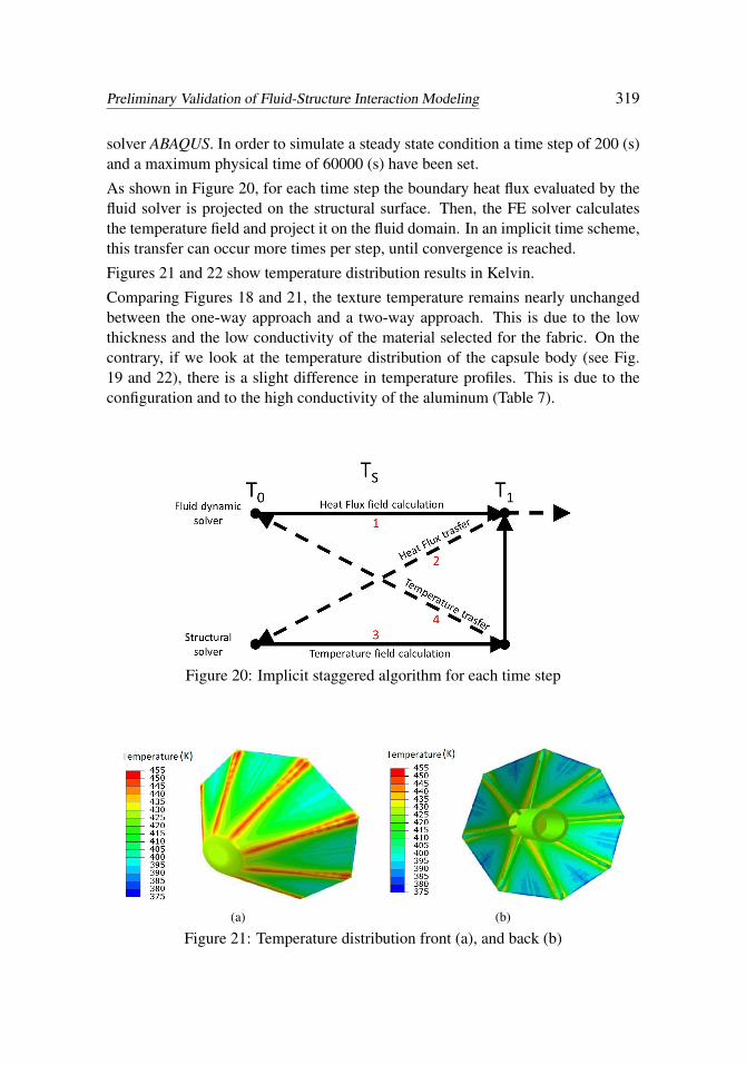
An implicit staggered numerical scheme (Figure 20) has been used to realize da-ta transfer between the Fluid Dynamic solver STAR-CCM+ and the FE structural
Preliminary Validation of Fluid-Structure Interaction Modeling 319
solver ABAQUS. In order to simulate a steady state condition a time step of 200 (s)and a maximum physical time of 60000 (s) have been set.
As shown in Figure 20, for each time step the boundary heat flux evaluated by thefluid solver is projected on the structural surface. Then, the FE solver calculatesthe temperature field and project it on the fluid domain. In an implicit time scheme,this transfer can occur more times per step, until convergence is reached.
Figures 21 and 22 show temperature distribution results in Kelvin.
Comparing Figures 18 and 21, the texture temperature remains nearly unchangedbetween the one-way approach and a two-way approach. This is due to the lowthickness and the low conductivity of the material selected for the fabric. On thecontrary, if we look at the temperature distribution of the capsule body (see Fig.19 and 22), there is a slight difference in temperature profiles. This is due to theconfiguration and to the high conductivity of the aluminum (Table 7).
Figure 20: Implicit staggered algorithm for each time step
(a) (b)
Figure 21: Temperature distribution front (a), and back (b)
A relatively flexible partitioned approach using commercial codes has been ana-lyzed to assess the aero-thermal behavior of Hypersonic Deployable re-entry sys-tems. Preliminary evaluation of uncoupled structural, fluid dynamic and thermalbehaviors have been obtained for a capsule configuration with a mechanically de-ployable TPS.
Thermo-structural comparisons have demonstrated the validity of ABAQUS codeto evaluate deflections induced by temperature fields. A maximum percentage errorof 10% has been calculated in the worst condition, comparing with the work ofGossard, for the case of a differential temperature of 339 (K).
Aero-thermal simulations have demonstrated the effectiveness of the partitioned ap-proach presented in this work. As highlighted in Figure 11, despite same materialproperties and environmental conditions have been selected, results obtained usingthe CFD-FEM coupling approach presented in Section 3.2 are closer to experimen-tal results obtained at NASA LaRC. This result permits to be more predictive in thedesign phase and provides the basis for a fully coupled CFD-FEM analysis, withthe purpose to predict more accurately the Aero-Thermo-Dynamic behavior.
The aero-thermal analysis performed in this work on an HDAD, considering a typi-cal suborbital reentry trajectory based on sounding rocket, illustrates the differencebetween a common one-way approach, and a two-way closely coupled partitionedapproach.
As expected, this difference results particularly marked if we consider the thermaldiffusion in a thick body with high conductivity. In this case, the possibility ofusing a Two-way approach, which takes into account the variation of the flow fielddue to the new thermal distribution inside the material, is more predictive in an
Preliminary Validation of Fluid-Structure Interaction Modeling 321
advanced design phase.
Moreover, we have calculated a maximum temperature of 428 (K) for the nose ofthe capsule and 455 (K) for the TPS fabric, which are significantly below nomi-nal maximum temperatures that aluminum and Nextel could tolerate, allowing useof off-the-shelves materials for a typical suborbital re-entry trajectory based on asounding rocket launch mission.
References
Akin, D. L. (1990): The parashield entry vehicle concept: basic theory and flight-test developments, in: Proceedings of the 4th Annual AIAA/Utah State UniversityConference on Small Satellites, Logan, UT, August 27–30.
Bassano, E.; Savino, R.; Lo Forti, R.; Ferrarotti, A.; Richiello, C.; Russo, G.;Aurigemma, R.; Punzo, F.; Dell’Aversana, P. (2011): IRENE – Italian re-entrynacelle for microgravity experiments, in: Proceedings of the 62nd InternationalAstronautical Congress, CapeTown, October 3–7, IAC-11.A2.7.7.
Beck, R. A. S.; Arnold, J. O.; White, S.; Fan, W.; Stackpoole, M.; Agrawal, P.;Coughlin, S. (2011): Overview of initial development of flexible ablators for hy-personic inflatable aerodynamic decelerators, 21st AIAA Aerodynamic DeceleratorSystems Technology Conference and Seminar 2011.
Bisplinghoff, R. L.; Dugundji, J. (1958): Influence of Aerodynamic Heating onAeroelastic Phenomena. Pergamon Press, 1958, pp. 288–312.
Carandente, V.; Elia, G.; Savino, R. (2013): Conceptual design of de-orbit andre-entry modules for standard CubeSats, in: Proceedings of the 2nd IAA Conferenceon University Satellite Missions and Cubesat Work-shop, Rome, February 4–7.
Carandente, V.; Savino, R. (2014): New concepts of deployable de-orbit andre-entry systems for CubeSat miniaturized satellites. Recent Pat. Eng., vol. 8, pp.2–12.
Carandente, V.; Savino, R.; D’Oriano, V.; Fortezza, R. (2014): Deployableaerobraking earth entry systems for recoverable microgravity experiments, in:Proceedings of the 65th International Astronautical Congress, Toronto, Canada,September 2014, IAC-14.A2.3.8.
Carandente, V.; Savino, R.; Iacovazzo, M.; Boffa, C. (2013): Aerothermal anal-ysis of a sample-return reentry capsule. Fluid Dynamics and Materials Process-ing, vol. 9, no. 4, pp. 461–484.
Carandente, V.; Zuppardi, G.; Savino, R. (2014): Aerothermodynamic and sta-bility analyses of a deployable re-entry capsule. Acta Astronautica, vol. 93, pp.291–303.
Cassell, A. M.; Swanson, G. T.; Keith Johnson, R.; Hughes, S. J.; Cheatwood,F. M. (2011): Overview of the hypersonic inflatable aerodynamic decelerator largearticle ground test campaign. 21st AIAA Aerodynamic Decelerator Systems Tech-nology Conference and Seminar 2011.
Culler, A. J.; McNamara, J. J. (2010): Studies on fluid-thermal-structural cou-pling for aerothermoelasticity in hypersonic flow. AIAA Journal, vol. 48, no. 8, pp.1721–1738.
Del Corso, J. A.; Bruce, W. E.; Liles, K. A.; Hughes, S. J. (2011): ThermalAnalysis and Testing of Candidate Materials for PAIDAE Inflatable Aeroshell. 21stAIAA Aerodynamic Decelerator Systems Conference, Dublin, Ireland May 23–26.
Del Corso, J. A.; Cheatwood, F. M.; Bruce, W.; Hughes, S. J.; Calomino, A.M. (2011): Advanced high-temperature flexible TPS for inflatable aerodynamicdecelerators. 21st AIAA Aerodynamic Decelerator Systems Technology Conferenceand Seminar, AIAA Paper 2011–2510.
Deveikis, W. D.; Hunt, L. R. (1973): Loading and Heating of a Large Flat plateat mach 7 in the Langley 8-foot high-temperature structures tunnel. NASA-TN-D-7275, L-8760.
Glass, C. E.; Hunt, L. R. (1988): Aerothermal tests of quilted dome models on aflat plate at a mach number of 6.5. NASA-TP-2804, L-16346, NAS 1.60:2804.
Goldman, B. D.; Scott, R. C.; Dowell, E. H. (2014): Nonlinear Aeroelastic Anal-ysis of the HIAD TPS Coupon in the NASA 8’ High Temperature Tunnel: Theoryand Experiment. NASA TM-2014-218267.
Goldman, B. D.; Dowell, E. H. (2015): In-Flight Aeroelastic Stability of the Ther-mal Protection System on the NASA HIAD, Part II Nonlinear Theory and ExtendedAerodynamics. 56th AIAA/ASCE/AHS/ASC Structures, Structural Dynamics, andMaterials Conference.
Goldman, B. D.; Dowell, E. H.; Scott, R. C. (2015): Aeroelastic stability of ther-mal protection system for inflatable aerodynamic decelerator. Journal of Spacecraftand Rockets, vol. 52, no. 1, pp. 144–156.
Gossard, M. L.; Seide, P.; Roberts, W. M. (1952): Thermal buckling of plates.NACA TN-2771.
Harper, B. P.; Braun, R. D. (2014): Preliminary Design Study of Asymmetric Hy-personic Inflatable Aerodynamic Decelerators for Mars Entry. AE8900 MS SpecialProblems Report, Guggenheim School of Aerospace Engineering Georgia Instituteof Technology Atlanta, GA.
Hughes, S. J.; Cheatwood, F. M.; Dillman, R. A.; Wright, H. S.; Del Corso,J. A.; Calomino, A. M. (2011): Hypersonic Inflatable Aerodynamic Decelerator
Preliminary Validation of Fluid-Structure Interaction Modeling 323
(HIAD) technology development overview. 21st AIAA Aerodynamic DeceleratorSystems Technology Conference and Seminar 2011.
Hughes, S. J.; Dillman, R. A.; Starr, B. R.; Stephan, R. A.; Lindell, M. C.;Player, C. J.; Cheatwood, F. M. (2005): Inflatable Re-entry Vehicle Experiment(IRVE) Design Overview. 18th AIAA Aerodynamic Decelerator Systems Technol-ogy Conference and Seminar, Munich, Germany, May 24–26.
Hughes, S. J.; Ware, J. S.; Del Corso, J. A.; Lugo, R. A. (2009): Deployableaeroshell flexible thermal protection system testing. 20th AIAA Aerodynamic De-celerator Systems Conference.
Iacovazzo, M.; Carandente, V.; Savino, R.; Zuppardi, G. (2015): Longitudinalstability analysis of a suborbital re-entry demonstrator for a deployable capsule. Ac-ta Astronautica, vol. 106, pp. 101–110.
Kramer, R. M. J.; Cirak, F.; Pantano, C. (2013): Fluid–structure interactionsimulations of a tension-cone inflatable aerodynamic decelerator. AIAA Journal,vol. 51, no. 7, pp. 1640–1656.
Litton, D. K.; Bose, D. M.; Cheatwood, F. M.; Hughes, S.; Wright, H. S.; Lin-dell, M. C.; Derry, S. D.; Olds, A. (2011): Inflatable re-entry vehicle experimen-t (IRVE) - 4 overview. 21st AIAA Aerodynamic Decelerator Systems TechnologyConference and Seminar 2011.
McNamara, J. J.; Friedmann, P. P. (2007): Aeroelastic and aerothermoelasticanalysis of Hypersonic vehicles: Current status and future trends. Collection ofTechnical Papers - AIAA/ASME/ASCE/AHS/ASC Structures, Structural Dynamicsand Materials Conference, pp. 3814.
McNamara, J. J.; Friedmann, P. P. (2011): Aeroelastic and aerothermoelasticanalysis in hypersonic flows: past, present, and future. AIAA Journal vol. 49, no. 6,pp. 1089–1122.
Savino, R.; Aurigemma, R.; Carandente, V.; Dell’Aversana, P.; Gramiccia, L.;Longo, J.; Marraffa, L.; Punzo, F. (2013): Study and development of a sub-orbital reentry demonstrator, in: Proceedings of the Italian Association of Aero-nautics and Astronautics XXII Conference, Naples, Italy, September 9–12.
Savino, R.; Carandente, V. (2012): Aerothermodynamic and feasibility study ofa deployable aero-braking re-entry capsule, Fluid Dyn. Mater. Process, vol. 8, no.4, pp. 453–477.
Sheta, E. F.; Venugopalan, V.; Tan, X. G.; Liever, P. A.; Habchi, S. D. (2010):Aero-structural assessment of an inflatable Aerodynamic Decelerator. NASA/CR-2010-216731, CFDRC Rept-8927/6, NF1676L-10953.
Smith, B. P.; Tanner, C. L.; Mahzari, M.; Clark, I. G.; Braun, R. D.; Cheat-wood, F. M. (2010): A historical review of inflatable aerodynamic decelerator tech-nology development, IEEE Aerospace Conference Proceedings.
Wang, Z.; Yang, S.; Liu, D. D.; Wang, X. Q.; Mignolet, M. P.; Bartels, R.E. (2010): Nonlinear aeroelastic analysis for a wrinkling aeroshell/ballute sys-tem. Collection of Technical Papers - AIAA/ASME/ASCE/AHS/ASC Structures,Structural Dynamics and Materials Conference.
Wilde, D.; Walther, S. (2001): Inflatable Re-entry and Descent Technology(IRDT)—further developments, in: Proceedings of the 2nd International Sympo-sium of Atmospheric Re-entry Vehicles and Systems, Arcachon, France.