XECOM (1) XE5617G XE5617G November 2007 World’s Smallest Global Fax and Data Modem for Embedded Systems Description The Xecom XE5617G is the world’s smallest complete, global modem for data and fax. The XE5617G fits in a 68-pin PLCC socket. Xecom calls this the Hybrid PLCC or HyPLCC™ package. Only Xecom offers a complete modem in a PLCC style package Every XE5617G module includes user transferable FCC Part 68 registration and Global Telecom compatibility. This eases the compliance burden on the system designer adding a modem to a process control, medical monitoring, point-of-sale, or remote diagnostic system. The XE5617G is pin compatible with other Xecom Hybrid PLCC models including the XE2420G, XE5690G and XE5692G.. Models XE5617G - V.92 data, V.34 fax; Hybrid PLCC Module Features • Small Size: less than 1 inch by 1 inch and just 0.29 inches thick • Data transfer rates, 300 bps to 56 Kbps • Fax transfer from 4800 bps to 14.4 Kbps • Control & configuration via AT commands. • 3.3 and 5 volt compatible serial interface • V.42 error control; V.42bis data compression. • Shared line features prevent modem operation from interfering with voice communications. • Complete integrated DAA. • Nonvolatile configuration storage • User transferrable FCC Part 68 registration • World-wide telephone network compliance. • UL60950 compliant • 3.3 Volt operation; • RoHS compliant • Versions operating at Temperatures of -40 o C to +85 o C operation are available Preliminary XE5617G BLOCK DIAGRAM
Transcript
XECOM (1) XE5617G
XE5617GNovember 2007
World’s Smallest Global Fax and Data Modem for Embedded Systems
Description
The Xecom XE5617G is the world’s smallestcomplete, global modem for data and fax. TheXE5617G fits in a 68-pin PLCC socket. Xecom callsthis the Hybrid PLCC or HyPLCC™ package. OnlyXecom offers a complete modem in a PLCC stylepackage
Every XE5617G module includes user transferableFCC Part 68 registration and Global Telecomcompatibility. This eases the compliance burden onthe system designer adding a modem to a processcontrol, medical monitoring, point-of-sale, or remotediagnostic system.
The XE5617G is pin compatible with other XecomHybrid PLCC models including the XE2420G,XE5690G and XE5692G..
Models
XE5617G - V.92 data, V.34 fax; Hybrid PLCCModule
Features
• Small Size: less than 1 inch by 1 inch and just0.29 inches thick
• Data transfer rates, 300 bps to 56 Kbps
• Fax transfer from 4800 bps to 14.4 Kbps
• Control & configuration via AT commands.
• 3.3 and 5 volt compatible serial interface
• V.42 error control; V.42bis data compression.
• Shared line features prevent modem operationfrom interfering with voice communications.
• Complete integrated DAA.
• Nonvolatile configuration storage
• User transferrable FCC Part 68 registration
• World-wide telephone network compliance.
• UL60950 compliant
• 3.3 Volt operation;
• RoHS compliant
• Versions operating at Temperatures of -40o Cto +85o C operation are available
Preliminary
XE5617G BLOCK DIAGRAM
XECOM (2) XE5617G
XE5617G Mechanical Specifications
a
b
c
d
c
f
g
e e
45O
i
(TOP)
Inches Millimeters
Dimension Min Typ Max Min Typ Maxa 0.280 0.285 0.290 8.76 8.89 9.02b 0.985 0.990 0.995 25.02 25.15 25.27c 0.950 0.955 0.960 24.13 24.26 24.38d 0.910 0.920 0.930 23.11 23.37 23.62e 0.045 0.050 0.055 1.15 1.27 1.40f 0.695 0.700 0.705 17.65 17.78 17.91g 0.195 0.200 0.205 10.03 10.16 10.29
i(radius) 0.015 0.020 0.025 0.13 0.25 0.38
i
i
.050”
XECOM (3) XE5617G
1 /DCD /DCD is an active low output from the modem. This output is controlled by the AT&Ccommand. In the default condition, AT&C1, /DCD indicates the presence of a validcarrier signal.
2 /CTS /CTS is an active low output from the modem. When hardware flow control is active,the modem asserts /CTS to indicate that it can accept data from the terminal equipmenton /TXD.
3 /RESET /RESET is an active low input which initiates a modem hardware reset. /RESET mustbe active for a minimum of 100 milliseconds for a proper modem reset sequence. Noexternal reset is required; if none is used, the /RESET signal should be left open.
4 /DSR /DSR is an active low output from the modem. The /DSR signal typically indicates thatthe modem has established a communications link. The AT&S command determinesthe operation of the /DSR signal.
5 /RTS /RTS is an active low input to the modem. When hardware flow control is active, /RTSindicates to the modem that the host has data to send.
6 /DTR /DTR is an active low input to the modem. The operation of /DTR is controlled by theAT&D command. As the default, AT&D2, the modem interprets /DTR as an indicationthat the Host is ready to communicate, and if /DTR is removed while the modem is on-line, the modem drops the connection and enters command mode.
PIN NAME DESCRIPTION
Pin Descriptions
XE5617G Pin Configuration
XECOM (4) XE5617G
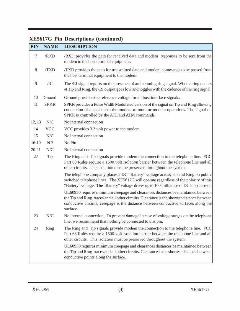
7 /RXD /RXD provides the path for received data and modem responses to be sent from themodem to the host terminal equipment.
8 /TXD /TXD provides the path for transmitted data and modem commands to be passed fromthe host terminal equipment to the modem.
9 /RI The /RI signal reports on the presence of an incoming ring signal. When a ring occursat Tip and Ring, the /RI output goes low and toggles with the cadence of the ring signal.
10 Ground Ground provides the reference voltage for all host interface signals.
11 SPKR SPKR provides a Pulse Width Modulated version of the signal on Tip and Ring allowingconnection of a speaker to the modem to monitor modem operations. The signal onSPKR is controlled by the ATL and ATM commands.
12, 13 N/C No internal connection
14 VCC VCC provides 3.3 volt power to the modem.
15 N/C No internal connection
16-19 NP No Pin
20-21 N/C No internal connection
22 Tip The Ring and Tip signals provide modem the connection to the telephone line. FCCPart 68 Rules require a 1500 volt isolation barrier between the telephone line and allother circuits. This isolation must be preserved throughout the system.
The telephone company places a DC “Battery” voltage across Tip and Ring on publicswitched telephone lines. The XE5617G will operate regardless of the polarity of this“Battery” voltage. The “Battery” voltage drives up to 100 milliamps of DC loop current.
UL60950 requires minimum creepage and clearances distances be maintained betweenthe Tip and Ring traces and all other circuits. Clearance is the shortest distance betweenconductive circuits; creepage is the distance between conductive surfaces along thesurface
23 N/C No internal connection, To prevent damage in case of voltage surges on the telephoneline, we recommend that nothing be connected to this pin.
24 Ring The Ring and Tip signals provide modem the connection to the telephone line. FCCPart 68 Rules require a 1500 volt isolation barrier between the telephone line and allother circuits. This isolation must be preserved throughout the system.
UL60950 requires minimum creepage and clearances distances be maintained betweenthe Tip and Ring traces and all other circuits. Clearance is the shortest distance betweenconductive points along the surface.
XE5617G Pin Descriptions (continued) PIN NAME DESCRIPTION
XECOM (5) XE5617G
XE5617G Electrical Specifications
VCC 3.13 3.3 3.47 Volts
ICC 80 85 mA On Line
Ring Voltage Detected 26 150 VRMS Type B Ringer
Ring Frequency Detected 15.3 68 Hz Type B Ringer
Telephone Loop Current 16 40 100 ma
Line Impedance 600 Ohms
Data Transmit level -12.0 -9.0 dBm
DTMF Transmit Level -2.5 0 dBm Avg over 3 second interval
Voh 2.4 5.0 Volts
Vol 0.4 Volts
Vih 2.0 5.0 Volts
Vil -0.3 0.8 Volts
Parameter Min Typ Max Units Comments
XE5617G ABSOLUTE MAXIMUM RATINGS
Storage Temperature -25O C to +85O C
1 Maximum Operating Temperature Range 0O C to +70O C
VCC 3.6 Volts
1 The XE5617G can be ordered as an Industrial Temperature Range part. These parts are screened for
operation from -40O C to +85O C. There is additional cost for this screening. Add the -ITR to theoriginal model number to specify the Industrial Temperature Range (ITR) screening.
XECOM (6) XE5617G
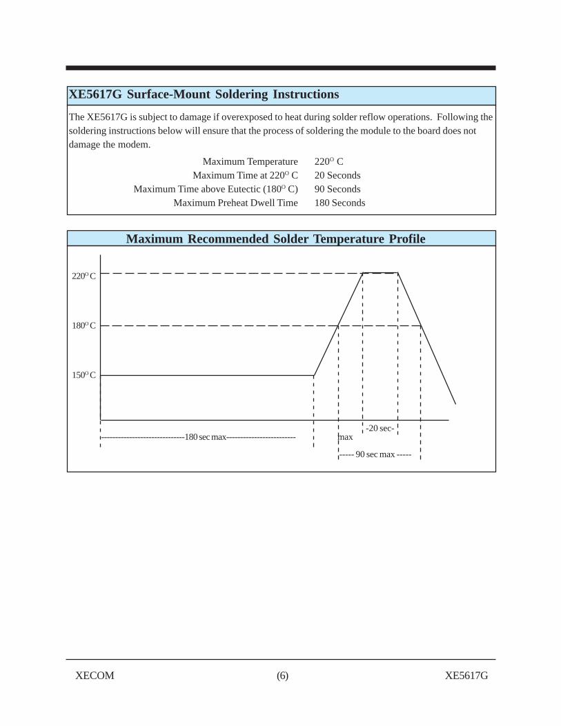
XE5617G Surface-Mount Soldering Instructions
The XE5617G is subject to damage if overexposed to heat during solder reflow operations. Following thesoldering instructions below will ensure that the process of soldering the module to the board does notdamage the modem.
Maximum Temperature 220O CMaximum Time at 220O C 20 Seconds
Maximum Time above Eutectic (180O C) 90 SecondsMaximum Preheat Dwell Time 180 Seconds
Maximum Recommended Solder Temperature Profile
220O C
180O C
150O C
-20 sec- ------------------------------180 sec max------------------------- max
----- 90 sec max -----
XECOM (7) XE5617G
Notes:
1 Capacitors, C1 and C2, may be required for EMI filtering in your system. Without these componentsyou may experience unintended radiation when the telephone cable is attached. C1 and C2 are high-voltage capacitors. We recommend the Novocap ES2211N681K502NXTM. This 680 pfd, 5000 voltcapacitor will direct the high frequency harmonics to the system ground.
2. F1 is a positive thermal coefficient (PTC) device which protects the modem from excessive currentflow. These devices are required for your system to pass UL60950. Fuses may be used in place of thePTC’s
XE5617G Typical Connection Diagram
Parts List for XE5617G Typical Connection Diagram
ReferenceDesignation Qty Description
C1, C2 2 Cap. 680 pfd, Y2
F1 1 PTC, TRF600-150
XECOM (8) XE5617G
XE5617G Connection Data
The XE5617G reports data on the current connection in response to the ATI11 command. Because manyof the reported parameters require an active connection, this command is best utilized from the on-linecommand mode accessed with the escape sequence. The items shown in italics are only valid during anactive call.
The Connection Report is presented in two pages. The first page will be displayed on receipt of the ATI11command. To move to the second page of the report hit any key. The table below describes theinformation provided in the Connection Report.
REPORTED ITEM DESCRIPTION
1 Last Connection Reports the modulation used on the last completed connection; values include:V.92PCM, V.92, V.90, V.34 and V.32
2 Initial Transmit Carrier Rate Upstream data rate first negotiated on last connection
3 Initial Receive Carrier Rate Downstream data rate first negotiated on last connection
4 Final Transmit Carrier Rate Upstream data rate at the end of the last connection
5 Final Receive Carrier Rate Downstream data rate at the end of the last connection
6 Protocol Negotiation Result Reports the error correction protocol negotiated on last connection; valuesinclude LAPM/SREC, LAPM, MNP, and none.
7 Data Compression Result Reports Link data compression protocol negotiated on last connection; valuesinclude LAPM, MNP, V.42bis, V.44 and none.
8 Noise Level Reports the estimated noise level in the modem signal.
9 Receive Signal Power Level Reports the approximate level of the incoming modem signal.
10 Transmit Signal Power Level Reports the level of the outgoing modem signal.
11 Round Trip Delay Reports how many milliseconds for the signal to be transmitted and returned.
12 Near Echo level Reports level of echoed signal in V.34 mode.
13 Far Echo Level Reports level of echoed signal in V.34 mode.
14 Transmit Frame Count Reports the total number of LAPM frames transmitted thus far during the call.
15 Transmit Frame Error Count Reports the number of transmitted frames rejected during the current call.
16 Receive Frame Count Reports the total number of LAPM frames received thus far during the call.
17 Transmit Frame Error Count Reports the number of received frames rejected during the current call.
18 Retrain by Local Modem Reports the number of retrain and rate renegotiations requested by the local modem.
19 Retrain by Remote Modem Reports the number of retrain and rate renegotiations requested by the remote modem.
20 Local Rate Renegotiation Reports the number of rate renegotiations requested by the local modem.
21 Remote Rate Renegotiation Reports the number of rate renegotiations requested by the remote modem.
22 Call Termination Cause Reports the reason for termination of the last call; 0, disconnect by local modemcommand, 1, loss of received modem carrier, 2, failed call attempt, 3,V.92, V.90 orV.34 training failure, and 4, protocol failure.
23 Robbed-Bit Signalling On PCM connections only reports the presence of robbed-bit signalling
24 Digital Loss (dB) On PCM connections only shows the digital signal loss
25 Remote Server ID On PCM lines indicates the ID of the remote server
26 Last PCM S Pointer Displays the last S pointer when the modem expected to enter PCM mode
XECOM (9) XE5617G
The XE5617G uses "AT" commands forconfiguration and control. This section describes theAT command format and lists the commands,registers and result codes.
Command Mode: The XE5617G enters commandmode on power-up, reset, a lost connection, orreceipt of the escape code. In command mode themodem accepts commands from the host ontransmit data. Appropriate result codes are returnedon received data.
Note: For backward compatibility some functionsare controlled by more than one command. In theseinstances the last command issued determines thefunction setting.
Command Line FormatAT commands follow a strict format. Eachcommand line, except A/, begins with the prefixAT. The "A" and "T" may be both upper case orboth lower case but cannot be of different cases.The modem determines data rate of the hostequipment by measuring the width of the incomingbits of the “A” and “T.”
Multiple commands may be combined into a singlecommand line of up to 40 characters. Commandsare executed in the sequence they appear uponreceipt of a carriage return. Spaces inserted into thecommand line are not placed in the buffer.
The command line can be edited with a backspacebefore it is executed. The backspace erases theprevious character in the command line. Register S5allows the user to select a character other thanbackspace to edit the command line.
XE5617G AT Commands
If the command buffer overflows, the modemissues an "ERROR" result code, and thecommand line is not executed. Register S3 allowsthe user to select a character other than a carriagereturn to terminate the command line.
Re-Execute Last Command - The A/command causes the modem to re-execute thelast command line. This is the only commandwhich does not require the "AT" prefix.
Omitted Parameters - Most commands includea parameter which determines how the functionswill be set. When the command parameter isomitted from the command string, it is assumed tobe a 0.
Escape Characters - A 3 character escapesequence may be entered to switch the modeminto command mode while on line. The escapecharacter, set by Register S2, must be entered 3times in succession to execute the escape. An ATcommand must then be entered within the perioddefined by S12 to enter command mode. Thedefault escape sequence is "+++."
Result Codes - The modem issues a result codeafter each action. Result codes may be sent asfull words, one or two digit numeric codes, or maybe disabled all together. Each result code endswith a carriage return when numeric result codesare chosen. When full word result codes arechosen, a Line Feed and Carriage Return precedeand follow each result code.
XECOM (10) XE5617G
XE5617G AT Commands
An asterisk indicates the factory default
A - Answer Command - Causes the modem toimmediately go off-hook and attempt to negotiate aconnection
D - Dial Command - Causes the modem to go off-hookand dial a remote modem. Below is a list of charactersaccepted in the dialing string.
0-9, A-D, #, * = Dialing DigitsL = Redial Last Number DialedP = Pulse dialS=n = Dial number stored in location nT = Tone dialW = Wait for dial tone, = Pause for the duration of S8! = Switch hook flash; = Return to the command state
En - Command Echo - Determines it the modem returnsthe commands received from the host.
n=0 Do not echo commandsn=1 Enable command echo *
Hn - Switch Hook Control - Controls the connection tothe telephone line.
In - Modem Identification - Provides product data..n=0 Modem identityn=1 ROM Checksumn=2 Verify Checksum,n=3 Driver Version Numbern=4 Data Pump Firmware Versionn=5 Code Versionn=9 Country IDn=11 Connection Data
Ln - Speaker Volume - Selects level of speaker output.n=0 Low Volumen=1 Low Volumen=2 Moderate Volume *n=3 High Volume
Mn - Speaker Activity - Determines when the speakerwill be active.
n=0 Speaker offn=1 Speaker on until carrier received *n=2 Speaker remains onn=3 Speaker on until DCD active
Nn - Link Negotiations - Selects how Register S37 willbe used to set the link negotiations
n=0 Connect only using the speed selected by S37n=1 Begin negotiations at the selected speed but
allow fallback *
On - On Line - Puts the modem back into data mode fromthe on-line command mode with or without a retrain.
n=0 Return On Line with no retrain *n=1 Initiate retrain while returning On line.n=3 Initiate rate renegotiation on return On line.
Qn - Responses - Determines if the modem will sendresponses to the host.
n=0 Send responses *n=1 No Responses
Sr? - Interrogate Register - Read value of selectedregister.
Sr=n - Set Register Value - Set value of selectedregister.
Vn - Result Codes - Determines what the type of resultcodes to be issued.
n=0 Numeric Result Codesn=1 English Word Result Codes*
Wn - Expanded Result Codes - Allows protocolmessages to be appended to the modem Connectresponses.
n=0 Report DTE Receive Speedn=1 Report DTE Receive Speed and protocol typen=2 Report DCE Receive Speed and protocol type *
XECOM (11) XE5617G
XE5617G AT Commands
Xn - Result Code Set - Sets the modem responsesn=0 Responses 0-4n=1 Responses 0-5 & 10n=2 Responses 0-6 & 10n=3 Responses 0-5, 7 & 10n=4 Responses 0-8 & 10*n=5 All Responsesn=6 All Responsesn=7 All Responses except extended result codes
Z - Reset - Causes an immediate modem soft reset andreconfigures the modem to the stored values
&Cn - Data Carrier Detect Operation - Determines howthe modem will present /DCD to the host.
n=0 /DCD forced active at all timesn=1 /DCD indicates modem carrier signal state *
&Dn - Data Terminal Ready Determines how themodem will react to the removal of /DTR from the host.
n=0 Modem ignores status of /DTRn=1 If /DTR is deactivated while the modem is on
line, the modem enters on-line command moden=2 /DTR must be active to maintain connection *n=3 Modem is reset when /DTR deactivated
&F - Restore Factory Configuration - Returnsconfiguration to its factory settings.
&Kn - Local Flow Control - Determines the operation offlow control between the modem and local host.
n=0 No Flow Controln=3 RTS/CTS (hardware) Flow Control *n=4 XON/XOFF (software) Flow Control
&Sn - Data Set Ready - Determines how the modem willpresent /DSR to the host.
n=0 Force DSR active *n=1 /DSR Indicates the modem’s readiness to
communicate
&Tn - Modem Test Modes - Modem diagnostics.n=0 Terminate Test in Progressn=1 Local Analog Loopback testn=3 Local Digital Loopback test
&V - View Active Configuration - Presents currentmodem configuration information
&W - Store Active Configuration - Places the currentconfiguration into the selected memory location whereit can be recalled on a soft reset.
&Zx=n - Store Number n in Location “x” - Permitsplacement of a telephone number in the selectedmemory location. Dialing the stored number isaccomplished with the s=n dial modifier where n is thememory location of the stored number.
x=0 Location 0n=1 Location 1n=2 Location 2
\Gn - In Band Flow Control - Determines how themodem handles received XON and XOFF flow controlcharacters.
n=0 Act on received XON and XOFF charactersn=1 Pass XON/XOFF characters in data stream
\Kn - Response to receipt of Break Signal (Data Mode)Determines how the modem will handle an receivedbreak signal.
n=0 Enter on-line command mode, do nottransmit break
n=1 Clear data buffers, transmit breakn=2 same as n=0n=3 Immediately transmit breakn=4 same as n=0n=5 Transmit nondestructive break in sequence
with data
XECOM (12) XE5617G
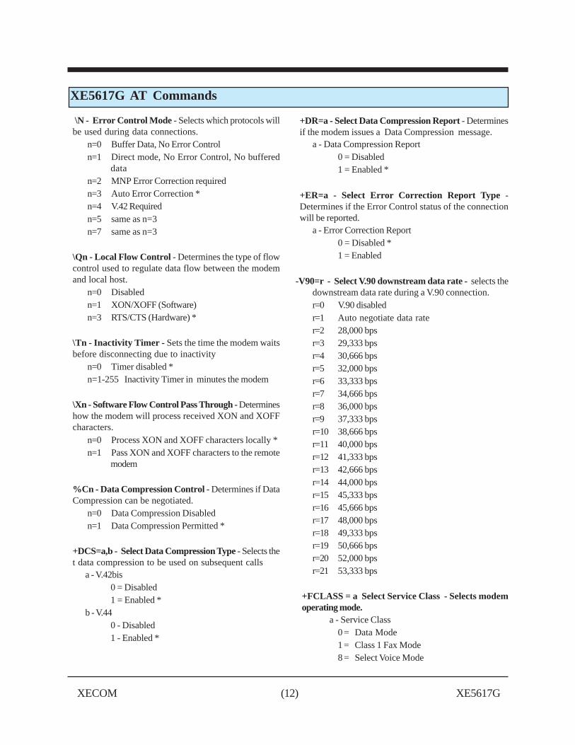
\N - Error Control Mode - Selects which protocols willbe used during data connections.
n=0 Buffer Data, No Error Controln=1 Direct mode, No Error Control, No buffered
datan=2 MNP Error Correction requiredn=3 Auto Error Correction *n=4 V.42 Requiredn=5 same as n=3n=7 same as n=3
\Qn - Local Flow Control - Determines the type of flowcontrol used to regulate data flow between the modemand local host.
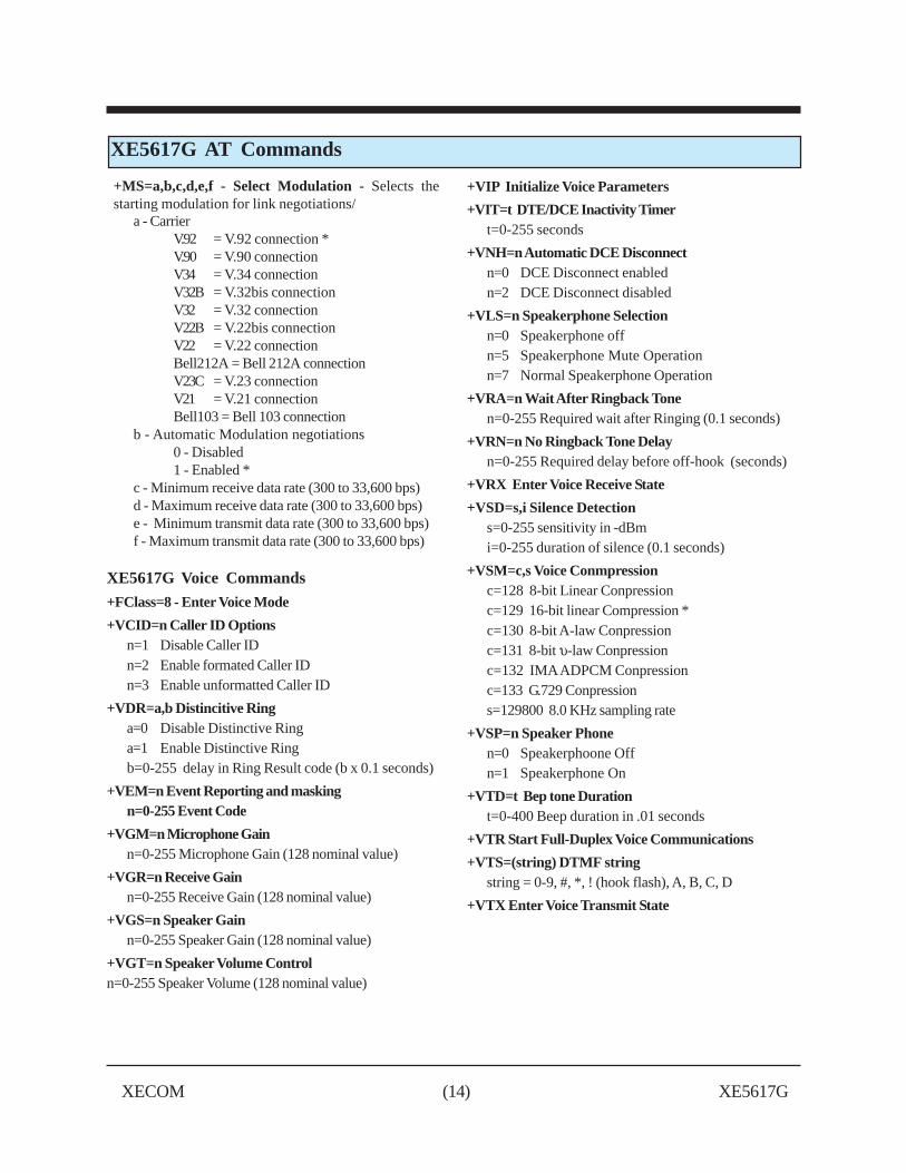
+FCLASS = a Select Service Class - Selects modemoperating mode.
a - Service Class0 = Data Mode1 = Class 1 Fax Mode8 = Select Voice Mode
XECOM (13) XE5617G
XE5617G AT Commands
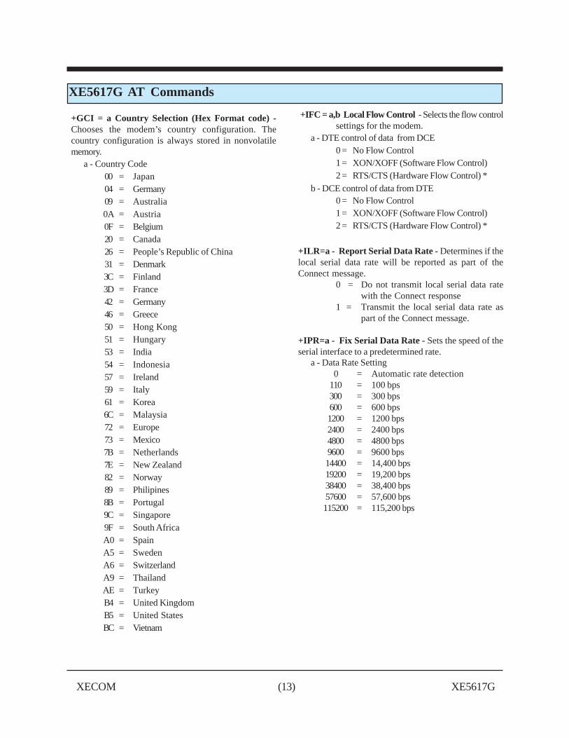
+GCI = a Country Selection (Hex Format code) -Chooses the modem’s country configuration. Thecountry configuration is always stored in nonvolatilememory.
b - Automatic Modulation negotiations0 - Disabled1 - Enabled *
c - Minimum receive data rate (300 to 33,600 bps)d - Maximum receive data rate (300 to 33,600 bps)e - Minimum transmit data rate (300 to 33,600 bps)f - Maximum transmit data rate (300 to 33,600 bps)
XE5617G Voice Commands
+FClass=8 - Enter Voice Mode
+VCID=n Caller ID Optionsn=1 Disable Caller IDn=2 Enable formated Caller IDn=3 Enable unformatted Caller ID
+VDR=a,b Distincitive Ringa=0 Disable Distinctive Ringa=1 Enable Distinctive Ringb=0-255 delay in Ring Result code (b x 0.1 seconds)
+VEM=n Event Reporting and maskingn=0-255 Event Code
+VGM=n Microphone Gainn=0-255 Microphone Gain (128 nominal value)
+VGR=n Receive Gainn=0-255 Receive Gain (128 nominal value)
+VGS=n Speaker Gainn=0-255 Speaker Gain (128 nominal value)
+FRS = a Receive Silencea - Required Silence in 10 msec increments values
0 to 255
+FTH = a Transmit HDLC Dataa - Select Modulation see +FRH for selections
+FTM = a Transmit Dataa - Select Modulation see +FRM for selections
+FTS = a Transmit Silencea - Requires the modem to end transmission and
wait before issuing OK response. The wait setby “a” is in 10 millisecond increments. Valuesof “a” range from 0 to 255.
XECOM (16) XE5617G
XE5617G REGISTER SETTINGS
S0 Answer on nth Ring: S0 sets the modem toautomatically answer on the nth ring. Setting S0 to0 disables automatic answer.Range: 0 to 255Units RingsDefault 0
S1 Ring Count: S1 is a read-only register showing thenumber of rings detected. If no ring is detectedwithin 8 seconds, S1 is reset.Range: 0 to 255Units RingsDefault 0
S2 Escape Character: S2 sets the ASCII escapecharacter. Values of 0-127 select valid characters;values from 128 to 255 disable the escapesequence.Range: 0 to 255Units ASCII CharacterDefault 43 (+)
S3 Line Termination Character: S3 determines theASCII character which will terminate commandsand modem responses.Range: 0 to 127Units ASCII CharacterDefault 13 (Carriage Return)
S4 Line Feed Character: S4 sets the ASCII characterto act as a line feed character in modem responses.Range: 0 to 127Units ASCII CharacterDefault 10 (Line Feed)
S5 Backspace Character: S5 defines the ASCIIcharacter used as a backspace to edit thecommand line.
Range: 0 to 127Units ASCII CharacterDefault 8 (Back Space)
S6 Dial Tone Wait Time: S6 determines how long themodem waits for dial tone before dialing. The DialTone Wait Time cannot be set to less than twoseconds.
Range: 0 to 255Units SecondsDefault 3
S7 Wait for Carrier after Dialing: S7 determineshow long the modem waits for a valid carriersignal after dialing.Range: 0 to 255Units SecondsDefault 60
S8 Comma Pause Time: S8 defines the duration ofthe pause initiated by a comma in the dialingstring when waiting for a second dial tone.Range: 0 to 255Units SecondsDefault 2
S10 Carrier Off Disconnect Delay: S10 selects howlong carrier must be lost to initiate a modemdisconnect.
Range: 1 to 255Units 0.1 SecondsDefault 20
S11 DTMF Dialing Speed: S11 determines theDTMF tone duration and spacing.
Range: 50 to 150Units millisecondsDefault 95
S12 Escape Code Guard Timer: S12 sets the modemguard timer. Anything received before or afterthe escape sequence, within the guard timer,causes the modem to abort the escape.Range: 10 to 255Units 0.02 SecondsDefault 50
S28 V.34 Modulation: S28 determines if V.34modulation can be used.
S28 = 0 DisabledS28 = 1 EnabledDefault: 1
S30 Disconnect Inactivity Timer: S30 sets howlong the modem remains on line with no dataflowing. A zero prevents the modem fromdisconnecting due to inactivity.Range: 0-255Units: MinutesDefault: 0
XECOM (17) XE5617G
XE5617G REGISTER SETTINGS
S35 Calling Tone: S35 determines if Calling Tone willbe present on a data call.S35 = 0 DisabledS35 = 1 EnabledDefault: 1
S36 Response to LAPM Negotiation failure: S36determines the action taken by the modem if theselected error correction negotiations areunsuccessful.S36 = 0 DisconnectS36 = 1 Maintain link with no error correctionS36 = 2 DisconnectS36 = 3 Maintain link with no error correctionS36 = 4 Attempt MNP; disconnect on MNP
failureS36 = 5 Attempt MNP; maintain link with no
error correction on MNP failureS36 = 6 Attempt MNP; disconnect on MNP
failureS36 = 7 Attempt MNP; maintain link with no
error correction on MNP failureDefault: 7
S37 Line Data Rate: S37 sets the maximum line datarate that can be negotiated. In V.90 mode thisregister controls the upstream data rate.0 = Automatic Negotiation2 = V.23, 1200/75 bps3 = 300 bps5 = 1200 bps6 = 2400 bps7 = 4800 bps8 = 7200 bps9 = 9600 bps10 = 12,000 bps11 = 14,400 bps12 = 16,800 bps13 = 19,200 bps14 = 21,600 bps15 = 24,000 bps16 = 26,400 bps17 = 28,800 bps18 = 31,200 bps19 = 33,600 bps *
S48 LAPM Error Control - S48 allows LAPM ErrorControl to be enabled or disabled.S48 = 128 LAPM DisabledS48 =7 LAPM EnabledDefault: 7
XECOM (18) XE5617G
XE5617G RESPONSES
Digits Verbose Description0 OK Command Successful
1 CONNECT 300 bps or higher connection
2 RING Ring signal detected
3 NO CARRIER Carrier not detected
4 ERROR Error in command line
5 CONNECT 1200 1200 bps Connection
6 NO DIAL TONE No dial tone detected
7 BUSY Busy signal detected
8 NO ANSWER Remote does not answer
10 CONNECT 2400 2400 bps Connection
11 CONNECT 4800 4800 bps Connection
12 CONNECT 9600 9600 bps Connection
13 CONNECT 14400 14,400 bps Connection
14 CONNECT 19200 19,200 bps Connection
18 CONNECT 57600 57,600 bps Connection
24 CONNECT 7200 7200 bps Connection
25 CONNECT 12000 12,000 bps Connection
40 CONNECT 300 300 bps Connection
55 CONNECT 21600 21,600 bps Connection
56 CONNECT 24000 24,000 bps Connection
57 CONNECT 26400 26,400 bps Connection
58 CONNECT 28800 28,800 bps Connection
59 CONNECT 31200 31200 bps Connection
60 CONNECT 33600 33,600 bps Connection
70 CONNECT 32000 32,000 bps Connection
71 CONNECT 34000 34,000 bps Connection
72 CONNECT 36000 36,000 bps Connection
73 CONNECT 38000 38,000 bps Connection
74 CONNECT 40000 40,000 bps Connection
75 CONNECT 42000 42,000 bps Connection
76 CONNECT 44000 44,000 bps Connection
77 CONNECT 46000 46,000 bps Connection
78 CONNECT 48000 48,000 bps Connection
79 CONNECT 50000 50,000 bps Connection
80 CONNECT 52000 52,000 bps Connection
81 CONNECT 54000 54,000 bps Connection
82 CONNECT 56000 56,000 bps Connection
86 CONNECT 16800 16,800 bps Connection
87 CONNECT 115200 115,200 bps Connection
88 DELAYED Dialing of this number is delayed due to success failed attempts
XECOM (19) XE5617G
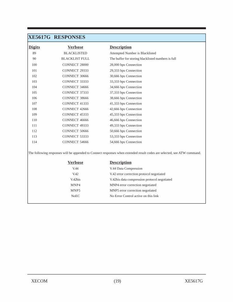
XE5617G RESPONSES
Digits Verbose Description89 BLACKLISTED Attempted Number is Blacklisted
90 BLACKLIST FULL The buffer for storing blacklisted numbers is full
100 CONNECT 28000 28,000 bps Connection
101 CONNECT 29333 29,333 bps Connection
102 CONNECT 30666 30,666 bps Connection
103 CONNECT 33333 33,333 bps Connection
104 CONNECT 34666 34,666 bps Connection
105 CONNECT 37333 37,333 bps Connection
106 CONNECT 38666 38,666 bps Connection
107 CONNECT 41333 41,333 bps Connection
108 CONNECT 42666 42,666 bps Connection
109 CONNECT 45333 45,333 bps Connection
110 CONNECT 46666 46,666 bps Connection
111 CONNECT 49333 49,333 bps Connection
112 CONNECT 50666 50,666 bps Connection
113 CONNECT 53333 53,333 bps Connection
114 CONNECT 54666 54,666 bps Connection
The following responses will be appended to Connect responses when extended result codes are selected, see ATW command.
Verbose DescriptionV.44 V.44 Data Compression
V.42 V.42 error correction protocol negotiated
V.42bis V.42bis data compression protocol negotiated
MNP4 MNP4 error correction negotiated
MNP5 MNP5 error correction negotiated
NoEC No Error Control active on this link
XECOM (20) XE5617G
FCC InstructionsThe XE5617G complies with Part 68 of the FCC Rules and Regulations. With each device shipped, thereis a label which contains the FCC Registration Number. The FCC Registration number incorporates theModel Number, Manufacturer Identifier, Product Type identifier and Ringer Equivalence Number (REN)for this product. You must, upon request, provide this information to your telephone company. The formatof the FCC Registration Number
US: DWEMM01BX5617G (pending)
The mounting of this device in the final assembly must be made in such a manner as to preserve the highvoltage protection between the TIP/RING Connection and the rest of the system. Typically, this may beaccomplished by maintaining a minimum spacing 100 mils between the TIP/RING Traces to the RJ-11CJack and low voltage portion of the system. No additional circuitry may be attached between TIP/RINGand the telephone line connection, unless specifically allowed in the rules.
The REN is useful to determine the quantity of devices you may connect to a telephone line and still haveall of these devices ring when the number is called. In most, but not all areas, the sum of the RENs of alldevices connected to one line should not exceed five (5.0). To be certain of the number of devices youmay connect to the line, as determined by the REN, you should contact the local telephone company todetermine the maximum REN for you calling area.
If your system causes harm to the telephone network, the telephone company may discontinue servicetemporarily. If possible, they will notify you in advance. If advance notification is not practical, you will benotified as soon as possible.
Your telephone company may make changes in its facilities, equipment, operations or procedures thatcould affect proper functioning of your equipment. If they do, you will be notified in advance to give youan opportunity to maintain uninterrupted telephone service.
If you experience trouble with this device, please contact XECOM at (408) 942-2200 for information onobtaining service or repairs. The telephone company may ask you to disconnect this device from thenetwork until the problem has been corrected or until you are sure that the device is not malfunctioning.
XECOM (21) XE5617G
Devices sold by XECOM are covered by the warranty provisions appearing in its Terms of Sale only. XECOM makes no war-ranty, express, statutory, implied, or by description regarding the information set forth herein, or regarding the freedom of the de-scribed devices from patent infringement. XECOM makes no warranty of merchantability or fitness for any purposes.XECOM reserves the right to discontinue production and change specifications and prices at any time and without notice. Thisproduct is intended for use in normal commercial applications. Applications requiring extended temperature range, unusual envi-ronmental requirements, or high reliability applications, such as military, medical life-support or life-sustaining equipment, arespecifically not recommended without additional processing and authorization by XECOM for such application.
Xecom assumes no responsibility for the use of any circuitry other than circuitry embodied in a Xecom product. No other cir-cuits, patents, or licenses are implied.
Xecom's products are not authorized for use as Critical Components in Life Support Devices or Systems.
Life Support Devices or Systems are devices or systems which, (a) are intended for surgical implant into the body, or (b) sup-port or sustain life, and whose failure to perform, when properly used in accordance with instructions provided in the labeling,can be reasonably expected to result in significant injury to the user.
A Critical Component is any component of a life support device or system whose failure to perform can be reasonably ex-pected to cause failure of the life support device or system, or to affect its safety or effectiveness.