Premium Automotive Research and Development Project (PARDP) Cold Metal Transfer (CMT) Brazing of Galvanised Steel Sheets. Project Summary Cold Metal Transfer (CMT) is a welding process developed by Fronius Welding, Austria. The process is based upon conventional Dip Transfer MIG welding where material deposition is initiated at the point of short circuit of the wire electrode into the molten weld pool. However, whereas traditional welding processes are controlled electrically CMT employs an innovative wire feed system, integrated to a high speed digital control which controls material transfer and the amount of thermal input to the work piece. CMT is characterised by an arcing period during which both the work surface and the wire electrode are heated. The molten electrode is then fed forward to make contact with the work surface. At the point of short circuit the welding current is cut practically extinguishing the welding arc and hence limiting the amount of heat transferred to the work piece. After a defined short circuit duration the electrode is mechanically retracted pinching the molten droplet from the end of the electrode. The arc is then re ignited and the process repeats. This hot cold, arc on arc off cycle is repeated up to 70 times per second depending on welding parameters employed. When compared to conventional MIG welding processes, CMT exhibits a high wire melting coefficient requiring in the region of 20 – 30% less thermal energy for welding. Although suited to a range of welding applications, notably thin aluminium, when considering arc brazing the process offers single sided access, with reduced part distortion - due to low thermal input, minimal weld spatter - greatly reducing the requirement for rework, and good gap bridging capabilities. This report details the results of PARDP trials conducted at WMG to evaluate the operating boundaries of this process (Process Window.) Trials were conducted based upon simple overlap joints constructed from DX52 galvanised steel sheets, brazed using a CuSi 3 filler wire in a pure Argon shielding environment. The weld power source used throughout these trials was a TPS3200 CMT unit integrated via Devicenet to an ABB IRB 2400L Robot. Owner: PARDP (C.Pickin) / AJT (mshergo1) Page 1 of 23 Last Updated 14/02/2007 Printed copies are uncontrolled
Transcript
Premium Automotive Research and Development Project (PARDP) Cold Metal Transfer (CMT) Brazing of Galvanised Steel Sheets.
Project Summary
Cold Metal Transfer (CMT) is a welding process developed by Fronius Welding, Austria. The
process is based upon conventional Dip Transfer MIG welding where material deposition is
initiated at the point of short circuit of the wire electrode into the molten weld pool. However,
whereas traditional welding processes are controlled electrically CMT employs an innovative
wire feed system, integrated to a high speed digital control which controls material transfer
and the amount of thermal input to the work piece.
CMT is characterised by an arcing period during which both the work surface and the wire
electrode are heated. The molten electrode is then fed forward to make contact with the
work surface. At the point of short circuit the welding current is cut practically extinguishing
the welding arc and hence limiting the amount of heat transferred to the work piece. After a
defined short circuit duration the electrode is mechanically retracted pinching the molten
droplet from the end of the electrode. The arc is then re ignited and the process repeats.
This hot cold, arc on arc off cycle is repeated up to 70 times per second depending on
welding parameters employed. When compared to conventional MIG welding processes,
CMT exhibits a high wire melting coefficient requiring in the region of 20 – 30% less thermal
energy for welding. Although suited to a range of welding applications, notably thin
aluminium, when considering arc brazing the process offers single sided access, with
reduced part distortion - due to low thermal input, minimal weld spatter - greatly reducing the
requirement for rework, and good gap bridging capabilities.
This report details the results of PARDP trials conducted at WMG to evaluate the operating
boundaries of this process (Process Window.) Trials were conducted based upon simple
overlap joints constructed from DX52 galvanised steel sheets, brazed using a CuSi3 filler wire
in a pure Argon shielding environment. The weld power source used throughout these trials
was a TPS3200 CMT unit integrated via Devicenet to an ABB IRB 2400L Robot.
Owner: PARDP (C.Pickin) / AJT (mshergo1) Page 1 of 23 Last Updated 14/02/2007 Printed copies are uncontrolled
Contents
1. Experimental Procedure
1.2. Applied Brazing Angles
2. Process Features
3. Comparative Analysis of Heat Input Between Brazing Processes.
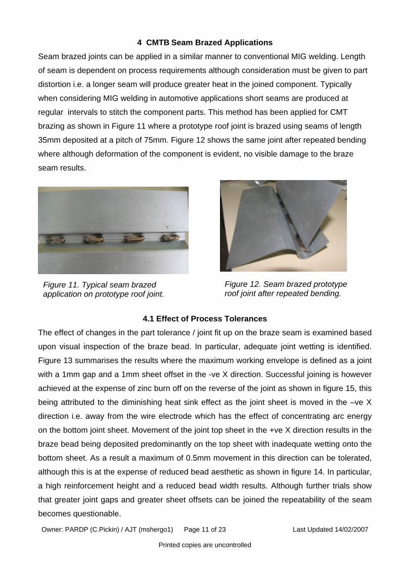
4. CMTB Seam Braze Applications
4.1. Effect of Process Tolerance.
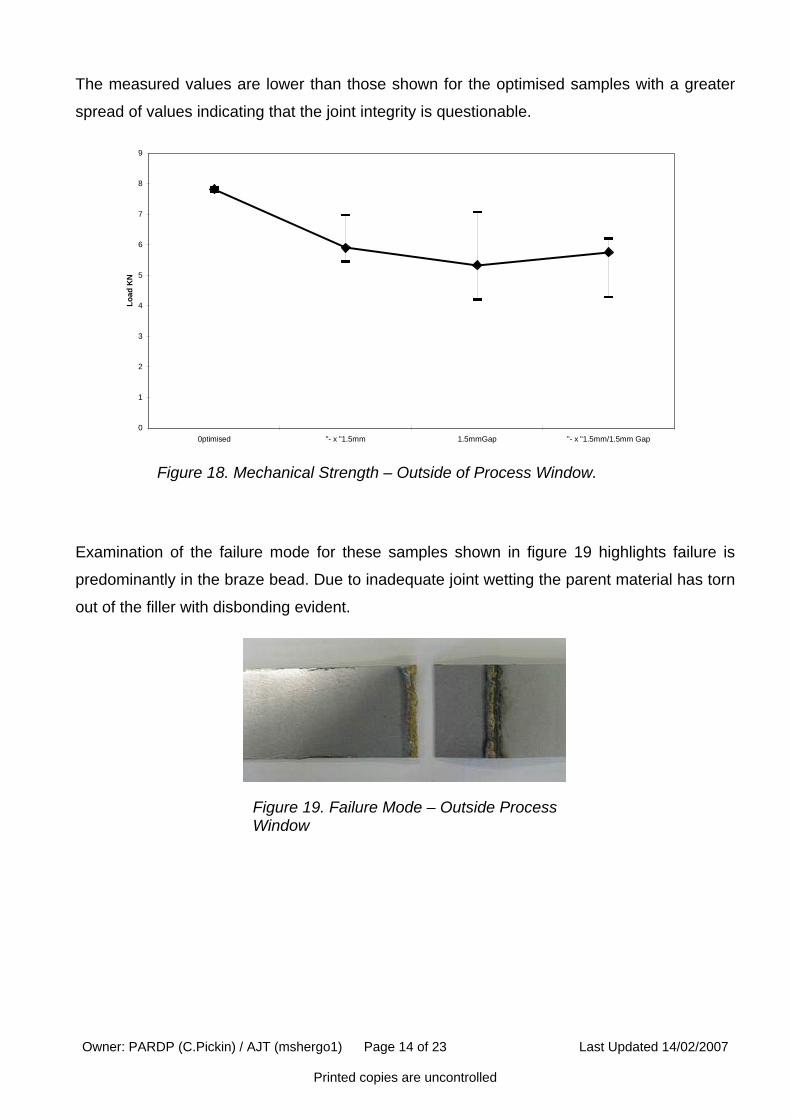
4.2. Mechanical Strength
5. CMTB Stitch Braze Applications
5.1. Examination of Braze Bead
5.2. Mechanical Properties.
5.3. Effect of Process Tolerance.
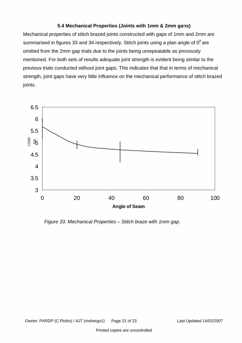
5.4. Mechanical Properties (Joints with 1mm and 2mm gaps)
5.5. Failure Mode.
6. Conclusion.
Owner: PARDP (C.Pickin) / AJT (mshergo1) Page 2 of 23 Last Updated 14/02/2007 Printed copies are uncontrolled
1. Experimental Procedure Experiments are conducted on simple lap joints constructed from 1mm thick material with a
20mm overlap and width of 100mm. Two separate sets of experiments are conducted.
• Seam Braze. Braze beads of 35mm length plan angle 00 as defined in figure 1.
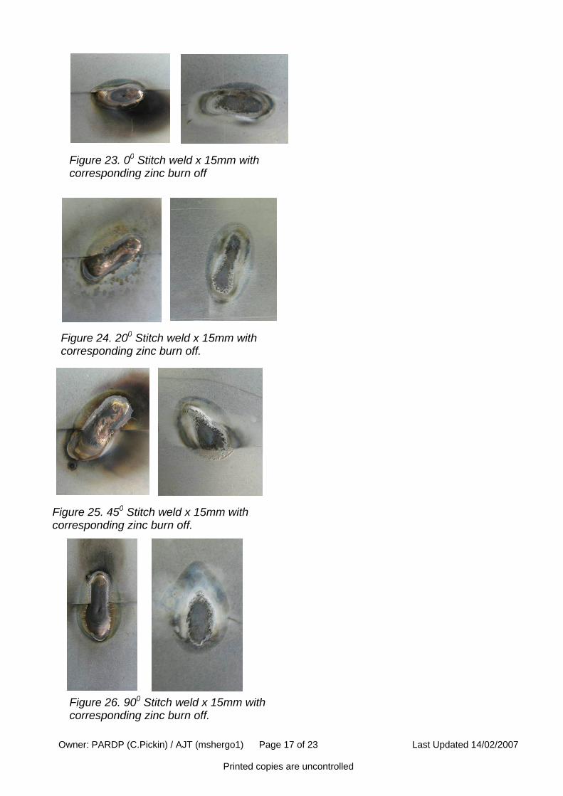
• Stitch Braze. Short braze beads of 15mm length using plan angles of 00,200,450, 900
as defined in figure 2.
For each experiment a total of 5-off samples are produced and an average of the results
presented. Samples were fixtured in a purpose made jig to ensure repeatability with clamps
situated 25mm either side of the joint line. In order that likely process condition can be
replicated packing material is used to control joint gaps at 1mm and 2mm where defined.
Top Sheet
Bottom Sheet
Figure 1: Braze Seam Sample Configuration. Braze direction arrowed.
00 200 450 900
Figure 2: Stitch braze sample configuration using a variety of angles, length 15mm. Braze direction arrowed. Not to scale, shown on one joint for representation only.
Top Sheet
Macroscopic analysis is based upon a section being removed from the joint half way along
the brazed bead in order that the influence of the start and end parameters can be
eliminated. For stitch braze joints the critical bead geometry is measured, this being defined
in figure 3.
Owner: PARDP (C.Pickin) / AJT (mshergo1) Page 3 of 23 Last Updated 14/02/2007 Printed copies are uncontrolled
Critical Bead Dimension
Braze bead, starts and ends retained.
Figure 3. Stitch Braze Critical Bead
Top Sheet
Mechanical testing is conducted on 35mm wide samples, accurately cut from the overlap
joint. For seam brazed joints the start and ends are retained in order that process conditions
can be replicated. For stitch brazed joints the critical bead dimension is centred in the middle
of the sample. Seam and stitch braze tensile sample configurations are shown in figure 4.
Each sample is deburred after cutting to eliminate the potential of crack propagation during
testing. Samples are tested in tension on an Instron 5356 using a crosshead speed of 10mm
min.
A
35mm
120m
m
B
Figure 4. Tensile sample configuration. A seam braze (starts and ends retained). B Stitch Braze. Not to scale.
Top Sheet
Top Sheet
Owner: PARDP (C.Pickin) / AJT (mshergo1) Page 4 of 23 Last Updated 14/02/2007 Printed copies are uncontrolled
1.1 Applied Brazing Torch Angles
Bead geometry is dependent upon applied brazed torch angles. When considering overlap
joints the available torch envelope is as much as 300 (900 – 600) as defined in figure 5.
However, consideration must be given to the effect on welding parameters when varying the
applied torch angles. Due to the heat sink effect of the overlap joint, when inclining the torch
into the overlap i.e. reducing the applied angle, greater thermal input is required in order that
bead geometry can be maintained and adequate wetting of braze filler to the parent material
can be achieved. This greater welding heat can in turn lead to greater part distortion and
unacceptable zinc burn off. When considering applied torch angles selection must be based
upon process conditions, in particular torch access. All documented brazing trials are
conducted using a torch incline angle of 900 unless otherwise stated. Electrode stick out is
maintained at 15mm
For standard MIG brazing a torch travel angle of 750 – 800 is typical. A recommendation from
the system supplier is that the torch travel angle be maintained at 60° when CMT brazing, in
order that arc heat can be dissipated ahead of the torch. Applying this travel angle also
ensures that zinc burn off is initiated ahead of the arc and prior to deposition of the filler
material, thus reducing the likelihood of the occurrence of porosity in the braze bead. Bead
on plate (BOP) trials show that when maintaining constant welding parameters and applying
an increased travel angle zinc burn off on the reverse joint sheet is evident. This suggests
that the arc is more focussed on the parent material resulting in greater localised thermal
input. If this angle is to be varied for example torch access, minor adjustments to the applied
welding parameters are required.
Stickout Length
00
900
600
Operating envelope
Figure 5. Torch Incline angle
Brazing Direction
600
00
Figure 6. Torch travel Angle.
Owner: PARDP (C.Pickin) / AJT (mshergo1) Page 5 of 23 Last Updated 14/02/2007 Printed copies are uncontrolled
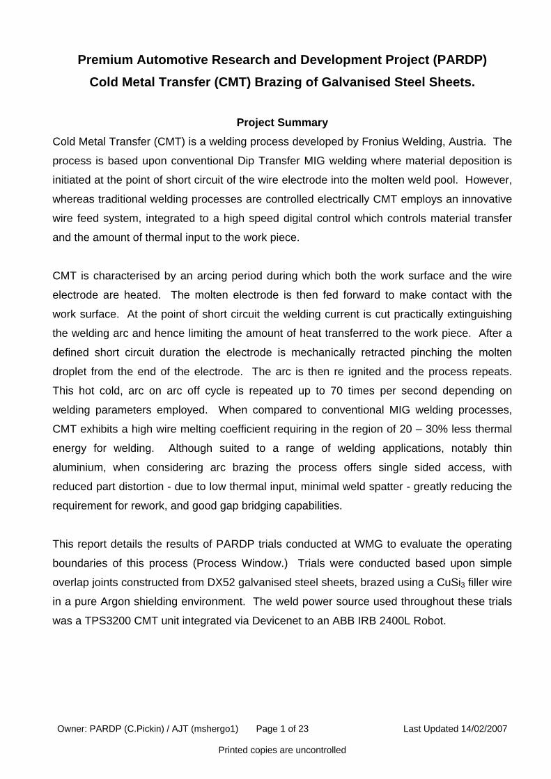
2. Process Features Simple bead on plate brazing trials are conducted to assess the operating principles of the
CMT process. Trials are conducted during which the electrical transients of the process are
captured and matched to high speed film images. A typical CMT braze cycle is shown in
figure 7. This is defined as the time required to deposit filler material onto the work surface /
joint and consists of two distinct phases of operation.
1. An arcing phase is evident represented by a constant arc voltage. This corresponds to
an initial high pulse of current which ignites the welding arc. This heats both the work
piece and the wire electrode. The current is then reduced in order that droplet
detachment is not initiated but that a molten globule remains attached to the end of the
electrode. The work surface is heated during this phase allowing vaporisation of the
zinc coating prior to filler material deposition.
2. After a defined duration the electrode is fed into the weld pool initiating an electrical
short circuit. This is represented by a reduction in arc voltage at this point. The
corresponding welding current is reduced to a minimum extinguishing the welding arc
and limiting the thermal energy transferred to the work piece. After a defined duration
the electrode is retracted and the molten droplet is pinched from the end of the
electrode and deposited on the work surface. The cycle then repeats.
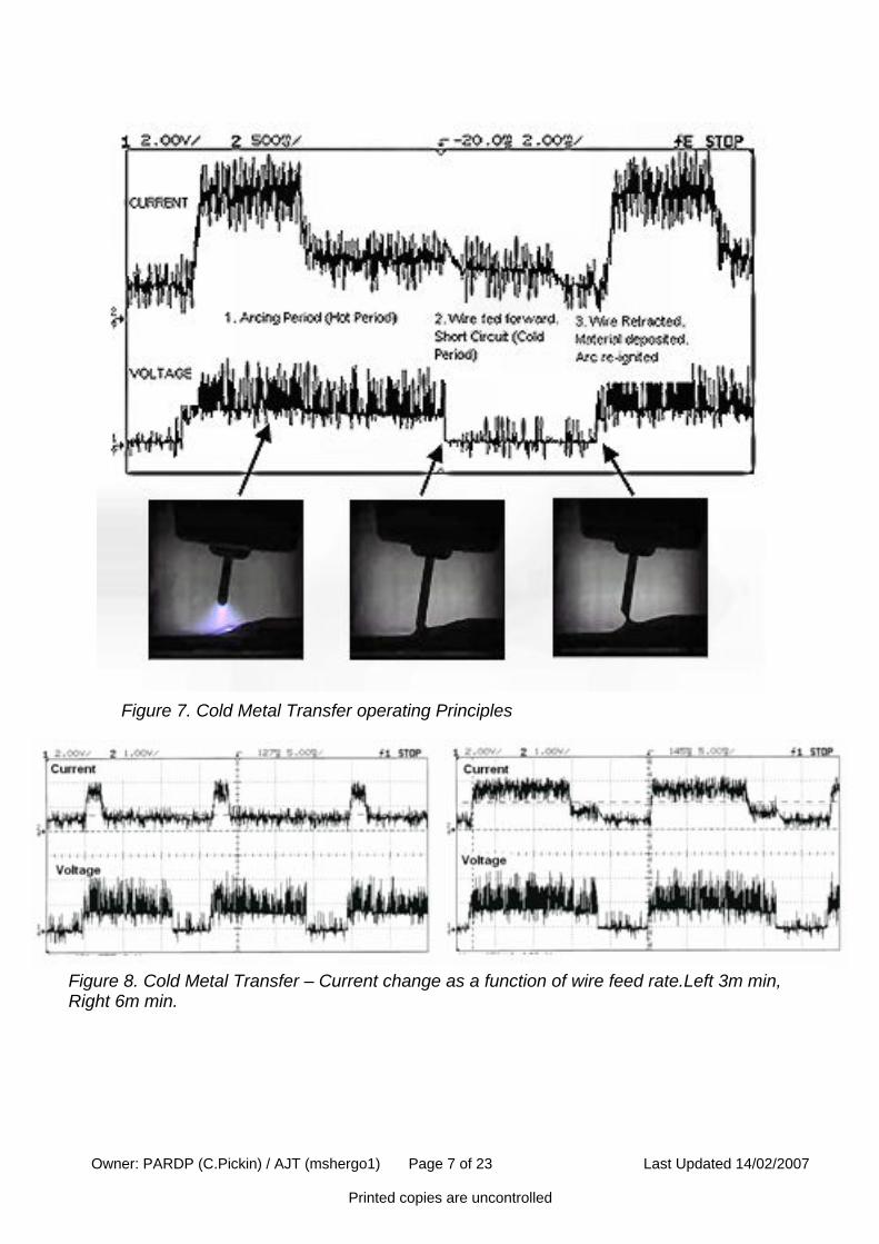
Reference to Figure 8 shows how the current is applied depending on the wire feed rate. At
lower wire feed rates the current is applied in an initial pulse before being reduced to a
minimum for the rest of the arcing period. This results in a low volume of electrode being
melted (this being proportional to the wire feed rate), and low thermal input transferred to the
work piece. As the wire feed rate is increased, greater current is required to melt a greater
volume of electrode and transfer more heat to the work piece. This is achieved by increasing
the duration of the initial arcing pulse of current which is then reduced to prevent material
transfer before being further reduced at the point of short circuit.
Owner: PARDP (C.Pickin) / AJT (mshergo1) Page 6 of 23 Last Updated 14/02/2007 Printed copies are uncontrolled
Figure 7. Cold Metal Transfer operating Principles
Figure 8. Cold Metal Transfer – Current change as a function of wire feed rate.Left 3m min, Right 6m min.
Owner: PARDP (C.Pickin) / AJT (mshergo1) Page 7 of 23 Last Updated 14/02/2007 Printed copies are uncontrolled
3. Comparative Analysis of Heat Input Between Brazing Processes BOP trials are conducted in which the heat input (HI) values of CMT brazing (CMTB), Dip
Transfer brazing (MIGB) and Pulsed MIG brazing (PMIGB) are computed. Based on BS EN
1011-11:1998 the HI values in J cm are calculated using the formula:
HI = nUI v
Where n is the arc efficiency factor, U and I are the mean values for arc voltage and arc
current respectively and v is the welding velocity in cm sec. The arc efficiency factor n is
assumed constant as n=0.8, this is defined as the overall thermal efficiency of the MIGB
process. Maintaining a constant welding velocity of 1m min-1 (1.666cm sec) wire feed is
incrementally increased and the process values recorded. Figure 9 shows the relationship
between HI and wf rates for the three brazing processes where CMTB exhibits substantially
lower thermal input to the work piece than the other processes for the same amount of filler
wire deposition.
100
300
500
700
900
1100
1300
1500
3 3.5 4 4.5 5 5.5 6 6.5 7 7.5 8
Wire Feed (Wf)
Hea
t Inp
ut (j
/cm
)
CMTDipPulse
Figure 9. Comparative Heat Input (HI) values of Brazing processes.
Further trials are conducted examining the comparative average wire electrode melting
coefficients of the three processes where using linear regression, the following relationship is
derived where Im is the average measured welding current.
CMTB wf = 0.0612Im
MIGB wf = 0.0499Im
PMIGB wf = 0.0575Im
Owner: PARDP (C.Pickin) / AJT (mshergo1) Page 8 of 23 Last Updated 14/02/2007 Printed copies are uncontrolled
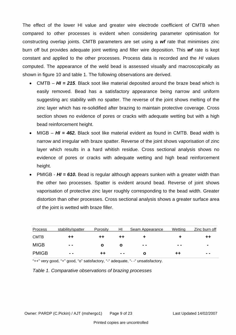
The effect of the lower HI value and greater wire electrode coefficient of CMTB when
compared to other processes is evident when considering parameter optimisation for
constructing overlap joints. CMTB parameters are set using a wf rate that minimises zinc
burn off but provides adequate joint wetting and filler wire deposition. This wf rate is kept
constant and applied to the other processes. Process data is recorded and the HI values
computed. The appearance of the weld bead is assessed visually and macroscopically as
shown in figure 10 and table 1. The following observations are derived.
• CMTB – HI = 215. Black soot like material deposited around the braze bead which is
easily removed. Bead has a satisfactory appearance being narrow and uniform
suggesting arc stability with no spatter. The reverse of the joint shows melting of the
zinc layer which has re-solidified after brazing to maintain protective coverage. Cross
section shows no evidence of pores or cracks with adequate wetting but with a high
bead reinforcement height.
• MIGB – HI = 462. Black soot like material evident as found in CMTB. Bead width is
narrow and irregular with braze spatter. Reverse of the joint shows vaporisation of zinc
layer which results in a hard whitish residue. Cross sectional analysis shows no
evidence of pores or cracks with adequate wetting and high bead reinforcement
height.
• PMIGB - HI = 610. Bead is regular although appears sunken with a greater width than
the other two processes. Spatter is evident around bead. Reverse of joint shows
vaporisation of protective zinc layer roughly corresponding to the bead width. Greater
distortion than other processes. Cross sectional analysis shows a greater surface area
of the joint is wetted with braze filler.
Process stability/spatter Porosity HI Seam Appearance Wetting Zinc burn off
CMTB ++ ++ ++ + + ++
MIGB - - o o - - - - - PMIGB - - ++ - - o ++ - - “++” very good, “+” good, “o” satisfactory, “-“ adequate, “- -“ unsatisfactory. Table 1. Comparative observations of brazing processes
Owner: PARDP (C.Pickin) / AJT (mshergo1) Page 9 of 23 Last Updated 14/02/2007 Printed copies are uncontrolled