PREMIUM QUALITY RAILS 1 Luca Gori 2 Abstract Competitiveness is the goal that all rail producers share as they strive to hold a leading position in a market that is more demanding and global today than ever before. Competitiveness means premium-quality rail and high-tonnage capacity at the lowest possible transformation costs. The plant builder’s mission is to provide rail producers with the most advanced technology available, in terms of both machinery and production processes, to enable them to reach their targets. Danieli’s continuous efforts in research and development have made it possible to introduce significant innovations in the production of rails. This article introduces the rail market trends and the process solutions developed by Danieli to build a modern rail mill. Keywords: Rail in-line; Rail Head Hardening; Profile sizing process; Ultra flexible reversing mill; Stand core concept stands. 1 Technical contribution to the 50 th Rolling Seminar – Processes, Rolled and Coated Products, November, 18 th to 21 st , 2013, Ouro Preto, MG, Brazil. 2 Vice President, Sales - Medium & Heavy Section Mills - Danieli Morgårdshammar, Buttrio (UD), Italy, Email: [email protected]
Transcript
PREMIUM QUALITY RAILS1
Luca Gori2
Abstract Competitiveness is the goal that all rail producers share as they strive to hold a leading position in a market that is more demanding and global today than ever before. Competitiveness means premium-quality rail and high-tonnage capacity at the lowest possible transformation costs. The plant builder’s mission is to provide rail producers with the most advanced technology available, in terms of both machinery and production processes, to enable them to reach their targets. Danieli’s continuous efforts in research and development have made it possible to introduce significant innovations in the production of rails. This article introduces the rail market trends and the process solutions developed by Danieli to build a modern rail mill. Keywords: Rail in-line; Rail Head Hardening; Profile sizing process; Ultra flexible reversing mill; Stand core concept stands. 1 Technical contribution to the 50th Rolling Seminar – Processes, Rolled and Coated Products,
November, 18th to 21st, 2013, Ouro Preto, MG, Brazil. 2 Vice President, Sales - Medium & Heavy Section Mills - Danieli Morgårdshammar, Buttrio (UD),
1 TECHNOLOGICAL MARKET REQUIREMENTS A key role in infrastructure development is played by railway transportation, which today is able to compete with medium-range flights, reducing road traffic and transportation costs as well as pollution and noise. New railway projects are focusing on the development of high-speed and heavy-haul lines, with safety being a must in both cases. In order to implement such a railway network, rails need to be ultra-long, with high-precision and increased service life, and feature top mechanical quality and wear resistance properties. Also, rail standards today have set tighter dimensional tolerances than in the past and have introduced a new classification philosophy based on hardness rather than on tensile strength. Historically, track was jointed together with splices; however, in more recent years jointed track has been replaced with long welded rail tracks. Welded track has been shown to reduce wear, reduce damage to trains, eliminate noise due to joints and provide an overall smoother ride. However, the welds are generally the main source of wear in a rail and the cause of faults. Long rails lower track installation costs, reduce the faults (fewer junctions) and reduce wear. For rail manufacturers long rails mean improved material yield, less guide and roll damage due to bar biting, less consumables (less cuts and drills), fewer operations at the finishing end (less saw & drill operations, handling, more productive loading) resulting in decreased labour. In Western Europe and North America, rail manufacturers typically provide a supply chain that includes not only the rails and their accessories (i.e. tongue rails, guard rails, steel sleepers, ribbed base plates, fish plates and clamps) but also installation service packages (i.e. welding, logistics, integrated supply package) and infrastructure service package (i.e. asset information services, maintenance and renewal). In other markets such as China, India, Russia and South America, the supply chain is usually limited to rails and their accessories. Although most rail sales are in competition all around the world, customers in countries with major manufacturers remain strongly domestic or regional (60% to 80% and even more) because of historical, technical and cultural ties between manufacturers and customers. It is not easy for a newcomer to the rail business to acquire technical knowledge or technologies. Last but not least, to be sustainable, rail manufacturing must have a low environmental impact.
2 STEEL QUALITY Rail specifications, as well as the manufacturing process itself, require excellent quality steel with low residuals, like copper and tin, as well as very low hydrogen content (less than 2 ppm). That is why most rail mills are part of an integrated steel plant where the feedstock is obtained from clean BOF steel. In North America, where today rail manufacturing uses only the electric steel route, scrap selection is important to melt steel with low residuals. Bethlehem Steel was the first in the world to produce electric steel rails in the 1980’s in their Steelton (Pennsylvania, USA) works.
Proper ladle treatment, including degassing, is mandatory in order to produce steel with the required metallurgical properties and without flakes, blowholes, etc. The alloying elements added to the LF determine the mechanical properties of rail steel. Carbon considerably increases hardness and wear resistance, tensile strength and bending strength but reduces impact strength and resistance to oxidation. Silicon is used to increase flexibility, yield strength and hardness and favours oxygen removal (less than 20 ppm). Manganese is added to increase toughness, tensile strength and wear resistance and to improve hot deformability. The addition of vanadium increases impact strength and fatigue limit and reduces grain growth. The addition of chromium, even if it leads to the formation of hard carbides, increases bending strength and tensile strength and reduces impact strength. The production of rails from blooms started only recently in the 1970’s (British Steel, Workington works); before that ingots were used. Submerged casting, mould hydraulic oscillating table, electric mould and final stirring, air mist secondary cooling and mechanical dynamic soft reduction are essential to obtain rail quality blooms. Most rail mills make use of rectangular blooms in sizes aimed at achieving better grain refinement and reduced segregation (Figure 1). It is common practice all over the world to start with a bloom size allowing a Reduction of Area (RoA) of at least 8. The minimum RoA is sometimes set by a standard (see GOST standards). The selected ratio between lengths of bloom sides is between 1.2 and 1.4 to achieve an almost evenly reduced final rail shape. The rectangular bloom shape also allows efficient re-heating.
Figure 1. Feedstock for rail mill.
3 UNIVERSAL ROLLING PROCESS FOR RAILS Today about half of rail production is rolled with the traditional caliber rolling method on 2-high reversing mills or 3-high mills and the other half with the more advanced universal rolling process. In 2006 at the Voestalpine Schienen rail mill in Donawitz (Austria) Danieli replaced the old 3-high mill with an Ultra Flexible Reversing (UFR) mill with three close coupled stands, out of which two are universal stands and one is two-high edging stand. The process of universal rail rolling was first tested at the Sacilor Hayange plant in France (today Corus Rail Hayange) in 1964. With universal rolling the entire rail section is simultaneously and homogeneously shaped by the four rolls of the universal stand (Figure 2), and the shape of the rail head remains almost unchanged during the whole rolling process, without the risk of fin or wrinkle formation. The rail contact surface, subject to high stress during use, is processed under constant direct pressure. An edging stand (with horizontal rolls only) sets the width of the rail head and the base.
The advantages offered by the universal rolling process are mainly:
Caliber rolling method
Universal rolling method
Intermediate shape
Final shape
Caliber rolling method
Universal rolling method
Intermediate shape
Final shape
Figure 2. Comparison of conventional caliber rolling and universal rolling method.
Reduction of the stresses produced in the rail section during the rolling process, which is due to the symmetrical shaping in the universal passes and the more compact shape of the leader section, which minimizes heat losses. The repetitive bending during pass progression in the caliber rolling method, using either box or diagonal calibres, causes wearing of the joint between the web and the head and between the web and the foot, thus changing the web height on the two sides. With the universal method there is no bending during pass progression. More adjustment possibilities of the mill stand with regard to rail section tolerances. The shaping in universal mill stands is divided into horizontal and vertical directions. Separate roll adjustment in these two shaping directions is possible. In the caliber rolling method the height of the rail, the rail symmetry, the width and the thickness of the foot are not controlled directly and depend on the wearing of the groove and thrust surface of the roll collars. With the universal method the above-mentioned dimensions are directly controlled and do not depend on groove wearing. The wearing of the thrust surface of the roll collars in the two or three-high mills causes increased foot thickness on one side of the rail and the consequent asymmetry of the head. Primary straightening of rails with asymmetric heads tilts the rail’s axis of symmetry. Drastic reduction of roll cost. Because of reduced friction between rail and rolls and the simple groove configuration in the universal stands, roll costs are considerably reduced. Finishing groove life is typically 2,500 tons for the universal stand and 1,500 tons with the caliber rolling method (single groove finisher). With ring-type universal rolls, average roll consumption drops to 0.8 kg/ton from the 2 kg/ton of the conventional caliber rolling method. Groove lubrication is not required. With the caliber rolling method, high friction in the groove requires that it be oil lubricated, resulting in additional costs as well as impacting the environment. Lower roll separating forces. Because of reduced friction between rail and roll in the universal mill stands, the roll separating forces are lower than those in conventional mill stands. Consequently, less energy is required for shaping. Danieli developed the innovative PSP (Profile Sizing Process) to obtain superior finished products and lower production costs.
The main features of this operating process are: High quality surface finish because the universal finishing stand is only used in the last finishing pass; Roughing and edging stand groove lifetime not determined by the finishing stand, resulting in longer roll life; Limited number of spare rolls in the workshop since deep roll redressing is not needed; Use of the Finishing Stand as a sizing stand; No tension between the penultimate and the last pass; All stands are shiftable.
Figure 3. : Typical rail pass schedule for PSP using a UFR mill with three close coupled stands.
The rolling process is shown in Figure 3. The leader pass is produced in the Breakdown Mill from a continuously cast rectangular bloom. In finishing rolling, five runs are accomplished in the UFR (Ultra Flexible Reversing) mill, with a total of five universal passes, four performed in the universal roughing (UR) stand and one in the universal finishing (UF) stand. Thanks to the shiftable stands, in the last run only a single pass is performed, thus eliminating any tension in the bar. The edging stand roll is fitted with three different grooves that are used in accordance with pass progression. Danieli mills are also designed to roll rail accessories such as tongue rails, guard rails, steel sleepers, ribbed base plates, fish plates and clamps to increase plant utilization.
4 HEAT TREATMENT OF RAILS
High-speed railways, heavy-haul railways and reduced track maintenance require rails with higher wear resistance. These requirements can only be fulfilled by heat treated rails. Studies done on tracks revealed that wear is predominant in curves with radii of less than 1,000 m, while Rolling Contact Fatigue (RCF) occurs between radii of 1,000 and 5,000 m. The use of heat treated rails is recommended for heavily loaded tracks on curves with radii below 5,000 m. Again, employing heat treated rails on tracks which are already showing moderate wear and RCF problems stops further degradation.
For instance, the improvement using the heat treated grade R350HT (European standard EN 13674-1 2009) compared to ordinary grade R260 is about 3 times for wear and at least 2 times for RCF. Expensive grinding and/or milling operations on rails can be substantially reduced, while unnecessary new capital investment caused by premature rail exchange can be avoided by using heat treated rail steel grades. In the past, rail hardening technology was developed by steel producers together with their research and development departments or with external research centers. Hardened rails have been available since the 1950’s. Both in-line and off-line systems are used. Off-line systems feature induction heating and air cooling. In-line systems make use of the heat coming from the rolling process followed by immersion cooling in a quenching bath or air cooling system. All the above systems are patented and not available to other steel producers. In order to provide its customers with a high added value product, Danieli, through intensive in-house research and development, decided to develop its own system, which is currently patent pending. Head hardening treatment is an economical and effective way to achieve improved mechanical characteristics in a rail, such as: High wear and plastic resistance; Crack-free surface. By means of: High degree of steel purity (starting material with minimum content of non-metallic inclusions); Ultra fine pearlite microstructure; Smaller grain size. The part of a rail which is most subject to wear is the head portion, particularly the top and inner side surfaces.
Danieli’s solution provides a new in-line method for the heat-treatment of rail heads with the above characteristics on the entire rolled length (Rail Head Hardening - RH2 system). Danieli’s RH2 system provides a substantial reduction (at least 20%) of production costs compared to off-line systems, thanks to: Lower energy consumption; Lower capital and running costs; Low environmental impact; Reduced manpower, lifting and transportation means; Higher productivity.
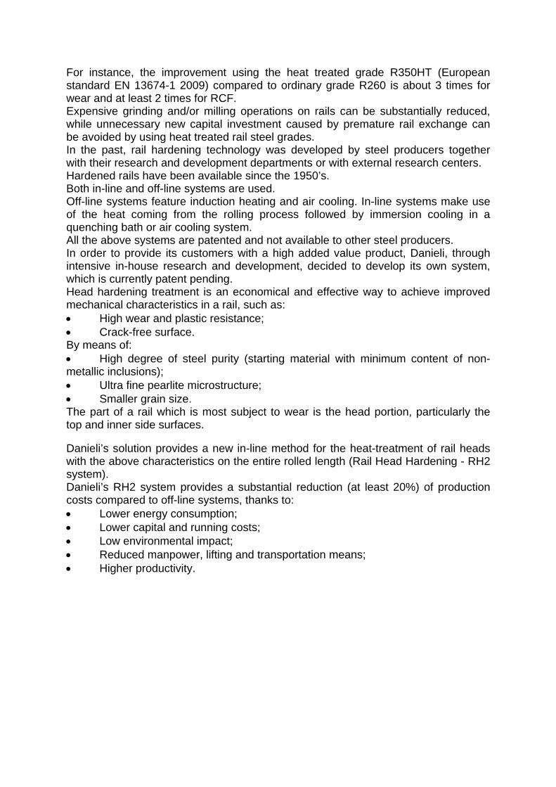
When they exit the rolling mill, rails are put through a three-step cooling process where the rail head is immersed in a tank containing a liquid cooling medium, after which it is naturally cooled and immersed again. Danieli chose the immersion method because, compared to the spray method, it guarantees more uniform mechanical properties of rails and it is possible to achieve the mechanical properties for carbon steel grades as required by applicable standards. During the first immersion step the temperature of the rail head is reduced without austenitic transformation. Then the rail is naturally cooled in order to reduce the temperature difference between the surface and the inner layers to obtain a uniform final grain size. During the final immersion step the austenite - pearlite transformation begins and ends.
Figure 4. Cooling curve of rail with RH2 system on CCT diagram.
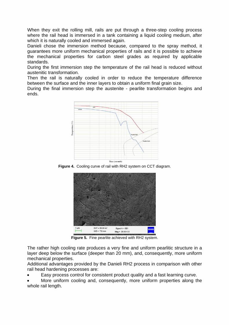
Figure 5. Fine pearlite achieved with RH2 system.
The rather high cooling rate produces a very fine and uniform pearlitic structure in a layer deep below the surface (deeper than 20 mm), and, consequently, more uniform mechanical properties. Additional advantages provided by the Danieli RH2 process in comparison with other rail head hardening processes are: Easy process control for consistent product quality and a fast learning curve. More uniform cooling and, consequently, more uniform properties along the whole rail length.
More flexible cooling rate by modifying the percentage and temperature of the quenchant. Guaranteed achievement of required metallurgical and mechanical properties according to any world standard; Lower residual stress.
5 ULTRA MODERN RAIL MILL LAYOUT Rail mills are generally designed so that parallel flange beams and other structural sections (such as parallel flange channels, angles, sheet piles) can be produced in addition to rails, thereby increasing plant utilization. The latest Danieli design features cutting-edge process and technology with very fast product changes from structural shapes to rails.
Figure 6. : Ultra modern rail mill layout. The walking beam type Re-Heating Furnace is able to properly heat up blooms and beam blanks in different steel grades to manufacture rails, parallel flange beams, channels, angles and sheet piles. It is equipped with ultra-low NOx emission (less than 50 ppm) MAB Flameless Technology burners distributed among several independently controlled heating zones to provide the required thermal output. Danieli PHL (Proportional High Low) logic, that combines the advantages of on-off firing and proportional flow control, is used to optimize head and tail feedstock discharging temperature to within 3 °C/m to suit the temperature differences along the bar when rolled. By combining flameless technology and managing each burner in on/off mode using PHL logic, the best combustion condition and temperature uniformity in the furnace chamber are achieved. The following control modes for each combustion zone can be selected by the operator: Modulated mode. PHL mode (on/off mode with round robin management). Flameless mode. PHL Flameless mode (on/off flameless with round robin management). By means of the MAB (Multi Air staging Burner) flameless technology managed by the PHL control logic, furnace chamber temperature uniformity above and below the pass line shows significant improvement, resulting in a temperature difference between bloom core and surface of less than 10°C. At reheat furnace exit side a 250-bar pressure water descaler ensures that the primary scale is removed before the feedstock is rolled. Depending on mill capacity or the final products to be manufactured, roughing can be done by one or two reversible Break-Down Mill stands.
A 1,150mm-roll-dia. breakdown mill (BDM) stand reduces the feedstock into the proper leader pass for the finishing mill. The BDM is equipped with entry and exit working roller tables, long side-wall manipulators with tilting fingers and grip-type bar turners for automatic rolling operations. The breakdown mill features a system that automatically changes the stand in less than 30 minutes. A disc saw is located at BDM exit side to perform head and tail cropping of the leader section, if required. Intermediate and finishing rolling is performed with the Profile Sizing Process (PSP), combining the Ultra Flexible Reversing (UFR) intermediate and pre-finishing mill featuring three close coupled Stand Core Concept (SCC) stands and a separate continuous finishing SCC stand.
Pre-finishing rolling takes place in the Ultra Flexible Reversing (UFR) mill consisting of three Stand Core Concept (SCC) stands, two of which are 1,200mm-roll-dia. universal stands. The UFR mill is equipped with entry and exit liftable roller tables to compensate for the different profile height and adjustable side guards to lead the bar into the roll groove. A system to automatically change the three stands in less than 30 minutes is provided as well. Downstream the UFR mill, at a suitable distance, a universal SCC stand (UF) performs the finishing pass. The UF stand is also equipped with entry and exit liftable roller tables and adjustable side guards as well as a system to automatically change the stand in less than 30 minutes. 250-bar pressure water descalers for secondary scale cleaning are provided at UFR mill entry and exit side and at UF stand entry side. With the PSP it is easier to install the HiProfile for in-line contactless measurement of hot sections. In order to unequivocally identify a rail so that it can be traced back to its manufacturer, its web is marked at UF stand exit side, as specified in the standards.
For example, the European standard EN 13674-1 2009 requires that the following information be marked on the rail: Identification number of its heat of origin (6 characters); Strand number and bloom position in the continuous casting sequence (3 characters); A letter indicating the position of the final rail inside the bloom. Since a bloom can produce several rails the machine must be able to change this letter during rolling. The marking data can be downloaded directly from level 2 automation system. A disc saw to perform tail cropping (to facilitate biting in the straightening line and prevent damage to straightening rings) and sampling (dimensional and quality) is provided at cooling bed entry side. Heat treatment of rails is performed in-line by the Danieli Rail Head Hardening (RH2) system, which runs at the same pace as the mill. The rail, lying on its side, is transferred by a series of lift and carry trolleys to the walking beam cooling bed. Because of its asymmetric shape with respect to the vertical axis, the rail tends to curve along its longitudinal axis due to the cooling difference between the head and the foot, which cools more quickly because of its lower mass. To offset this phenomenon the trolleys that load the rails onto the cooling bed have to be able to traverse independently so that the rail is pre-curved in the direction opposite to that caused by natural cooling. In this way, once the straightening temperature (less than 50°C) is reached, the rail will be almost straight, thus facilitating the straightening phase and limiting residual stress. Even the trolleys that pick up the rails exiting the cooling bed have to be able to move independently so they can follow the natural curvature of the rail after cooling. The straightening line located at cooling bed exit is made up of a bar turner followed by a 9-roller horizontal straightener and a 7-roller vertical straightener. The bar turner grabs the rail lying on its side as it exits the cooling bed and places it upright before feeding it into the horizontal straightener. The straightness tolerances specified in the rail standards are very strict, especially those referring to high-speed tracks. For example, the European standard EN 13674-1 2009 states for Class A rails (the highest quality rails) a maximum deviation of 0.3 mm from ideal straightness along the vertical axis (measured with a 3-m reference ruler) and 0.45 mm along the horizontal axis (measured with a 1.5-m reference ruler). To ensure the required rail straightness the roller straightening machines are designed for extreme rigidity, featuring backlash-free coupling between sleeves and shafts, individually driven rollers, automatic zeroing of rollers after each roller change, optimal roller diameter and pitch. Both straighteners are designed to accomplish a complete roller set change in less than 30 minutes. When structural sections are rolled, the vertical straightening machine is by-passed with a roller table. After straightening, the bars are delivered to two different finishing ends according to product type. The structural sections are cut to final length by metallic disc saws, stacked, tied, weighed and collected.
The finishing end for rails is designed for cutting and drilling operations, rail end straightening (if necessary) and final in-line inspection without moving the rails to a service center. Final certification of rail quality requires that automatic quality control systems be installed in-line. The rails are processed in the Non-Destructive Testing (NDT) center, where internal defects (such as non-metallic inclusions and discontinuities) are detected by ultrasonic system and surface defects (such as rolled-in scrap and laps) are detected by eddy current system. If a defect is detected the system sprays paint on the affected rail area to facilitate final bar conditioning. A profile and straightness measuring system certifies final rail geometry and straightness. The finishing end for rails is designed to allow rail backflow if a second inspection is required in the NDT center or to remove the defective rails from the main production flow. Carbide sawing and drilling machines make the final cut to length and the holes on the rail ends if needed. These machines must comply with the close cutting tolerances specified in applicable standards, in terms of squareness of ends, length and holes. Depending on customer requirements, rails may have up to 3 holes maximum on one or both ends. Depending on the center distance between the rollers of the roller straightening machines, the curvature of some rail ends may be greater than the allowed camber specified in the standards. To eliminate this curvature, gag presses are placed throughout the finishing end, generally after final cutting-to-length, to straighten the rail along both its axes simultaneously. These machines are usually fitted with an integrated straightness measuring system for fully automatic operation. Before dispatching, the rails are visually inspected by the quality control staff and, upon customer request, can also be weighed. The inspection includes: Dimensional check of the rails using the control templates specified in the standards; Measuring of rail length using a certified metric roller; Repair, if necessary, by grinding the surface defects detected in the NDT center and those detected visually (scratches, bruises). The inspection bed is equipped with a tilting system to inspect all the rail sides, facilitating inspection and repair operations. The rails are eventually collected on different benches according to their final length (12.5, 25 or 100 m). The cranes that transfer the rails to the wagons are provided with grip type hoists to pick up a maximum of four 100-m-long rails at the same time. This type of modern mill is intended for extremely high quality sale orders that require specialized software to ensure enhanced operation. The main functions performed by the automation control system are: Complete, fully automatic, rolling process management from feedstock yard up to rail storage area; Production program management; Full rolling process simulation;
Re-heating furnace thermal model and optimization algorithm for proper material re-heating and energy consumption reduction; Hydraulic Gap Control (HGC) and Automatic Gauge Control (AGC) in UFR mill and UF stands; Material tracking, production and quality-relevant data logging; Roll management, equipment life tracking; Quality control system. Multi-processors, featuring 1 ms sample time, are used for high-performance open and closed-loop control such as: - Hydraulic Gap Control (HGC) for the SCC stands. This is a closed-loop regulating function providing fast (response time under 50 ms) and accurate positioning of the rolling rolls (gap tolerance less than 0.1 mm). The position regulator provides reference to the hydraulic capsule servovalve and receives the position feedback from the position sensors. The regulator output is linearized to compensate for the servovalve gain variation due to the pressure drop across the servovalve (Butterfly Compensation) and for the oil compression caused by pressure changes between load and no-load conditions (Oil Volume Compensation). - Automatic Gauge Control (AGC). It aims to hold the exit gauge constant by compensating for the changes in stand stretching due to dynamic changes in rolling force. It is a control loop external to HGC position loop. To avoid large movements of the rolling rolls during biting, the hydraulic capsules are pre-closed in no-load conditions according to the Theoretical Mill Stretch. The calculation of this figure is based on expected rolling forces for each rolling pass. These forces are based on roll pass design or can be retrieved from the data stored in the previous rolling campaigns of the same product. 6 ROLLING PROCESS With the feedback from the experience acquired in the major revamping of the Voestalpine Schienen rail mill, which today is considered to be a technological industry benchmark for rail manufacturing, Danieli has developed innovative processes, technology and know-how in the field of rail mills. The intermediate and finishing rolling process, based on the Profile Sizing Process (PSP), makes use of three close coupled stands in the UFR mill and a separate universal finishing (UF) stand as shown in Figure 10. Only three runs are applied in the UFR, with a total of four universal passes, and one universal pass in the UF stand. Compared to the PSP, which uses only a UFR mill with three close coupled stands, this configuration: Increases productivity; Features less roll wearing; Provides better surface finish; Accomplishes controlled temperature rolling without jeopardizing productivity.
7 STAND CORE CONCEPT (SCC) STANDS FOR PRE-FINISHING AND FINISHING MILL
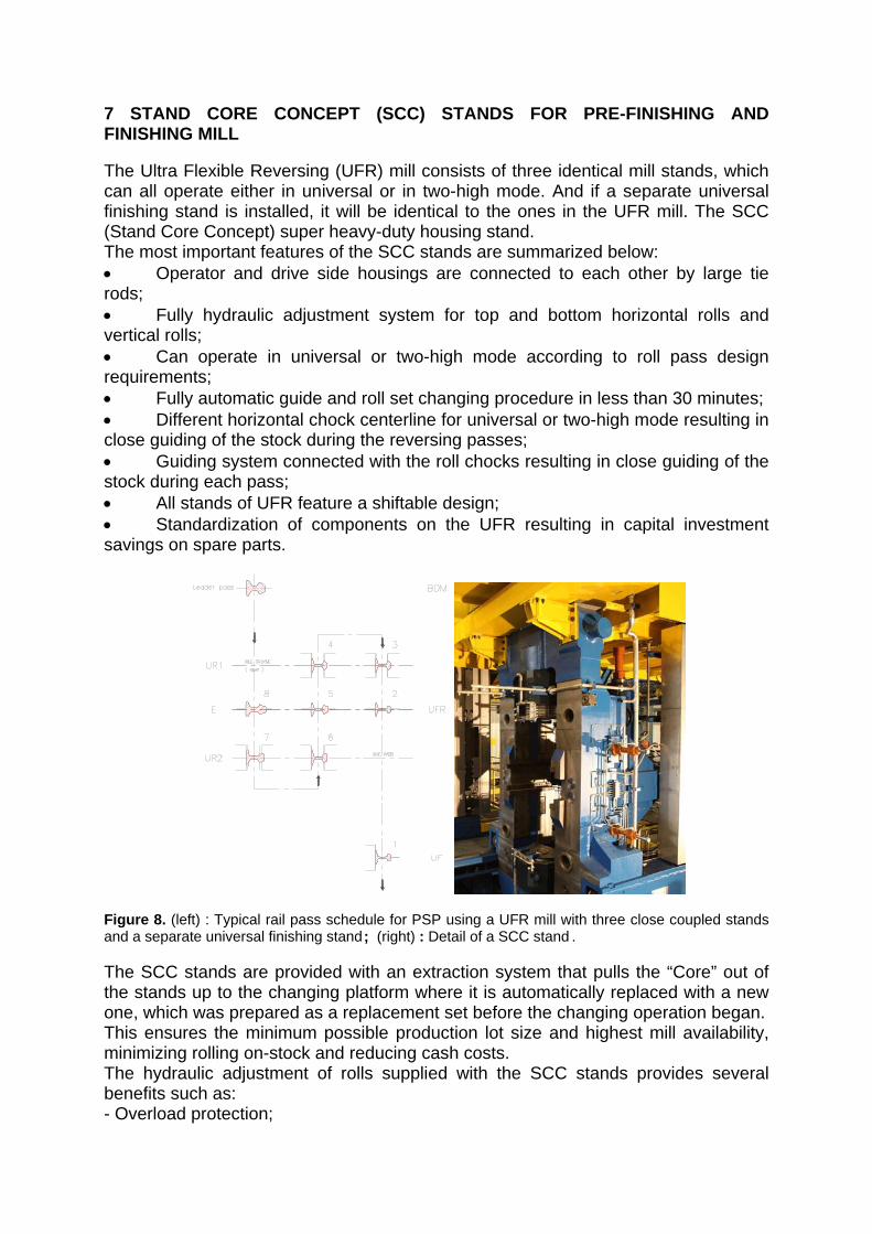
The Ultra Flexible Reversing (UFR) mill consists of three identical mill stands, which can all operate either in universal or in two-high mode. And if a separate universal finishing stand is installed, it will be identical to the ones in the UFR mill. The SCC (Stand Core Concept) super heavy-duty housing stand. The most important features of the SCC stands are summarized below: Operator and drive side housings are connected to each other by large tie rods; Fully hydraulic adjustment system for top and bottom horizontal rolls and vertical rolls; Can operate in universal or two-high mode according to roll pass design requirements; Fully automatic guide and roll set changing procedure in less than 30 minutes; Different horizontal chock centerline for universal or two-high mode resulting in close guiding of the stock during the reversing passes; Guiding system connected with the roll chocks resulting in close guiding of the stock during each pass; All stands of UFR feature a shiftable design; Standardization of components on the UFR resulting in capital investment savings on spare parts.
Figure 8. (left) : Typical rail pass schedule for PSP using a UFR mill with three close coupled stands and a separate universal finishing stand ; (right) : Detail of a SCC stand . The SCC stands are provided with an extraction system that pulls the “Core” out of the stands up to the changing platform where it is automatically replaced with a new one, which was prepared as a replacement set before the changing operation began. This ensures the minimum possible production lot size and highest mill availability, minimizing rolling on-stock and reducing cash costs. The hydraulic adjustment of rolls supplied with the SCC stands provides several benefits such as: - Overload protection;
- Zeroing and mill modulus determination after each changing procedure; - Exact roll gap setting; - Highest adjusting accuracy; - Under load gap regulation; - Tight product tolerances; - Consistent dimensional tolerances along the bar length.
8 CONCLUSIONS New railway projects are developed for high-speed and heavy-haul lines. Both lines require rails with lengths over 100 m and with wear resistant properties. High speed lines require additionally rails having high precision. The above mentioned rail characteristics can be achieved using: the universal rolling method, very stiff Stand Core Concept (SCC) stands, Automatic Gauge Control (AGC) in Ultra Flexible Reversing (UFR) mill and UF stands, repeatable process thru a specialized automation control system and Rail Head Hardening (RH2) system. With this embedded know-how acquired from experience in the field and strong design and manufacturing capabilities, Danieli has developed innovative processes and technologies for rail manufacturing. By using such innovative processes and technologies, rail manufacturers will be able to supply superior quality rails.
BIBLIOGRAPHY 1 L. Maestrutti, L. Gori, “Rolling technology for medium and heavy section mills”, MPT
International magazine, April 2009 issue, pages 40-42.