Prepaid Energy Metering 2011 Acknowledgment We express our wholehearted gratitude to our guide & project coordinator ………………….. who spent his valuable time in guiding us in selection and completion of our project. His vast experience, profound knowledge and willingness have been a constant source of inspiration and driving force for us throughout this project. We are thankful to our ……………., head of the department for giving valuable advices and support at the time of need. We express our deep gratitude to………………., principal for providing the necessary infrastructure to carry out our project. We are very much thankful to…………….., librarian for extending his cooperation in helping us by providing all the necessary references and good library facility. We heartily thank all the teaching and non teaching staff of our department for their cooperation given to us during our course of study. Last but not the least, we wish to remember forever the help rendered by our Friends during this study period Project Assoc Names…………. Page 1
Transcript
Prepaid Energy Metering 2011
Acknowledgment
We express our wholehearted gratitude to our guide & project coordinator …………………..
who spent his valuable time in guiding us in selection and completion of our project. His vast
experience, profound knowledge and willingness have been a constant source of inspiration and
driving force for us throughout this project.
We are thankful to our ……………., head of the department for giving valuable
advices and support at the time of need.
We express our deep gratitude to………………., principal for providing the
necessary infrastructure to carry out our project.
We are very much thankful to…………….., librarian for extending his cooperation in
helping us by providing all the necessary references and good library facility.
We heartily thank all the teaching and non teaching staff of our department for their
cooperation given to us during our course of study.
Last but not the least, we wish to remember forever the help rendered by our Friends
during this study period
Project Assoc
Names………….
Page 1
Prepaid Energy Metering 2011
Abstract
A scheme of Electricity billing system called PREPAID ENERGY METER
WITH TARIFF INDICATOR can facilitate in improved cash flow management in energy
utilities and can reduces problem associated with billing consumer living in isolated area and
reduces deployment of manpower for taking meter readings. Every consumer can buy a memory
card (is nothing but an EEPROM IC) with a password stored inside it using a MC program. The
memory card is available at various ranges (i.e. Rs 50, Rs 100, Rs 200 etc?).In our project we
have given the name for memory card as smart card.
When the consumer insert a smart card into the card reader which is connected in ?
prepaid energy meter with tariff indicator kit. Then the card reader will read the stored
information and delete the information from the EEPROM IC (smart card) using the MC
program. So that the smart card cannot be reused by others. Suppose if a consumer buys a card
for Rs.50/- he / she can insert this amount through the card reader so that prepaid energy meter
with tariff indicator kit will be activated. According to the power consumption the amount will
be reduced. When the amount is over, the relays will automatically shutdown the whole system.
In our project we also have a provision to give an alarm sound to consumer before the whole
amount is reduced.
Page 2
Prepaid Energy Metering 2011
Table of Contents1. Introduction
Page 3
Prepaid Energy Metering 2011
Introduction
The Electrical metering instrument technology has come a long way from what it was
more than 100 years ago. From the original bulky meters with heavy magnets and coils, there have
been many innovations that have resulted in size & weight reduction in addition to improvements
in features and specifications. Resolution and accuracy of the meter have seen substantial
improvements over the years. Introduction of the digital meter in the later part of last century has
completely changed the way Electrical parameters are measured. Starting with Voltmeters &
Ammeters, the digital meter has conquered the entire spectrum of measuring instruments due to
their advantages like ease of reading, better resolution and rugged construction. Of particular
significance is the introduction of the Electronic Energy Meter in the mid eighties.
Now a days, the energy consumption and energy distribution has became a big subject for
discussion because of huge difference in energy production and consumption. In this regard,
energy consumers are facing so many problems due to the frequent power failures; another
important reason for power cuts is due to the un-limited energy consumption of rich people. In
this aspect, to minimize the power cuts and to distribute the energy equally to all areas, some
restriction should have over the power consumption of each and every energy consumer, and
according to that the Government should implement a policy, by introducing Autonomous
Energy Meters everywhere in domestic sector. Hence, the need has come to think on this line and
a solution has to be emerged out.
Electrical Metering Instrument TechnologyToday the metering instrument technology grown up significantly, such that the consumed
energy can be calculated mathematically, displayed, data can be stored, data can be transmitted,
etc. Presently the microcontrollers are playing major role in metering instrument technology.
The present project work is designed to collect the consumed energy data of a particular energy
consumer through wireless communication system (without going to consumer house), the
system can be called as automatic meter reading (AMR) system. The Automatic Meter reading
Page 4
Prepaid Energy Metering 2011
system is intended to remotely collect the meter readings of a locality using a communication
system, without persons physically going and reading the meters visually.
1.2 Details About Electronic Energy MeterThe following are the advantages of electronic energy meter:
1.2.1 Accuracy
While electromechanical meters are normally available with Class 2 accuracy, electronic
meters of Class 1 accuracy are very common.
1.2.2 Low Current Performance
Most of the electromechanical meters tend to run slow after a few years and stop
recording at low loads typically below 40% of their basic current. This is due to increased
friction at their bearings. This results in large losses in revenue since most of the residential
consumers will be running at very low loads for almost 20 hours in a day. Electronic meters
record consistently and accurately even at 5% of their basic current. Also they are guaranteed to
start recording energy at 0.4% of their basic current.
1.2.3 Low Voltage Performance
Most of the mechanical meters become inaccurate at voltages below 75% of rated
voltage whereas electronic meters record accurately even at 50% of rated voltage. This is a major
advantage where low voltage problem is very common.
1.2.4 Installation
The mechanical meter is very sensitive to the position in which it is installed. If it is not
mounted vertically, it will run slow, resulting in revenue loss. Electronic meters are not sensitive
to their mounting position.
Page 5
Prepaid Energy Metering 2011
1.2.5 Tamper
The mechanical meters can be tampered very easily even without disturbing the wiring
either by using an external magnet or by inserting a thin film into the meter to touch the rotating
disc. In addition to these methods, in the case of a single-phase meter, there are more than 20
conditions of external wiring that can make the meter record less. In the case of 3 Phase meter,
external wiring can be manipulated in 4 ways to make it slow. Hence, any of these methods
cannot tamper electronic meters. Moreover they can detect the tampering of meter by using
LED.
1.2.6 New Features
Electronic meters provide many new features like prepaid metering and remote metering
that can improve the efficiency of the utility.
1.2.6.1 Remote Metering of Energy Meters
The introduction of electronic energy meters for electrical energy metering has
resulted in various improvements in the operations of utilities apart from the increase in revenue
due to better recording of energy consumption. One such additional benefit is the possibility of
reading the meters automatically using meter-reading instruments even without going near the
meter. Meter reading instruments (MRI) are intelligent devices with built in memory and
keyboard. The meter reader can download the energy consumption and related information from
the electronic meter into the meter reading instrument either by connecting the MRI physically to
the meter using their communication ports or by communicating with the meter from a distance
using Radio Frequency (RF) communication media. RF communication method is similar to a
cordless telephone, which is quite common these days. The meter and the MRI are provided with
an antenna. When the meter reader presses a button on the MRI, it communicates with the meter
through RF and asks for all the data that are preset. The meter responds with all relevant data like
meter identification number, cumulative energy consumed till that time etc. After reading many
meters like that in one MRI, the meter reader can go to the office and transfer all these data into a
Page 6
Prepaid Energy Metering 2011
computer, which will have all these data for the previous billing period. Using these two data, the
computer calculates the consumption for the current billing period and prepares the bill for each
consumer.
The use of RF communication enables the utility to install the meters on top of the
electric pole out of reach of the consumers thereby eliminating chances of tamper of the meter.
Frequencies in the range of 400 MHz to 900 MHz are commonly used for this purpose. However
other frequencies can also be used. If the distance between meter and MRI is of the order of 10
or 15 meters, this communication can be achieved using low power transmitters at reasonable
costs.
Power line carrier communication is another method of remote metering. In this method,
the meter data is transferred to an MRI or computer by using the power line itself as the medium
of transmission. This solution is generally cheaper than RF but needs good quality power lines to
avoid loss of data. This method is more attractive for limited distance communication.
Third medium of communication possible is telephone line. This is viable only for
industrial meters like the Trivector meter because of the cost of Modems required and the need
for a telephone line, which may not be available in every house. This medium has the advantage
of unlimited distance range. Remote metering is typically not a default option, but something
provided for selected customers. The preferred customer base may include suspicious clients or
those located very close to others, such as in a high-rise building. In the latter case, tens or
hundreds of meters may use RF to send billing data to a common collector unit, which then
decodes the data with microcontrollers or computers.
1.2.6.2 PREPAYMENT METERING
Yet another advantage of the electronic meter is the possibility of introducing prepaid
metering system. Prepaid metering system is the one in which the consumer pays money in
advance to the utility and then feeds this information into his meter. The meter then updates the
credit available to the consumer and starts deducting his consumption from available credit.
Page 7
Prepaid Energy Metering 2011
Once the credit reaches a minimum specified value, meter raises an alarm. If the credit is
completely exhausted, the meter switches off the loads of the consumer.
Main advantage of this system is that the utility can eliminate meter readers. Another
benefit is that they get paid in advance. The consumer benefits due to elimination of penalty for
late payment. Also it enables him to plan his electricity bill expenses in a better manner. Due to
the intelligence built in into the electronic meters, introduction of prepaid metering becomes
much easier than in the case of electromechanical meters.
Prepaid Energy MeteringEnergy meters, the only direct revenue interface between utilities and the consumers,
have undergone several advancements in the last decade. The conventional electro-mechanical
meters are being replaced with electronic meters to improve accuracy in meter reading. Asian
countries are currently looking to introduce prepaid electricity meters across their distribution
network, buoyed up by the success of this novel methodology in South Africa. The existing
inherent problems with the post-paid system and privatization of state held power distribution
companies are the major driving factors for this market in Asia.
Over 40 countries have implemented prepaid meters in their markets. In United Kingdom
the system, has been in use for well over 70 years with about 3.5 million consumers. The prepaid
program in South Africa was started in 1992, since then they have installed over 6 million
meters. Other African counties such as Sudan, Madagascar are following the South African
success. The concept has found ground in Argentina and New Zealand with few thousands of
installations.
The prepaid meters in the market today are coming up with smart cards to hold
information on units consumed or equivalent money value. When the card is inserted, the energy
meter reads it, connects the supply to the consumer loads, and debits the value. The meters are
equipped with light emitting diodes (LED) to inform consumers when 75 percent of the credit
energy has been consumed. The consumer then recharges the prepaid card from a sales terminal
Page 8
Prepaid Energy Metering 2011
or distribution point, and during this process any changes in the tariff can also be loaded in the
smart card.
Benefits of Prepaid Energy Metering
Improved operational efficiencies: The prepaid meters are likely to cut the cost of meter
reading as no meter readers are required. In addition, they eliminate administrative hassles
associated with disconnection and reconnection. Besides, going by South Africa’s experience,
prepaid meters could help control appropriation of electricity in a better way than conventional
meters.
Reduced financial risks: Since the payment is up-front, it reduces the financial risk by
improving the cash flows and necessitates an improved revenue management system.
Better customer service: The system eliminates billing delay, removes cost involved in
disconnection/reconnection, enables controlled use of energy, and helps customers to save
money through better energy management.
Market Drivers
Power sector reforms: The upcoming competitive and customer focused deregulated power
distribution market will force the market participants to make the existing metering and billing
process more competent. This is likely to drive the prepaid market.
Increasing non-technical losses: Metering errors, tampering with meters leading to low
registration and calibration related frauds are some of the key components of non-technical
losses. India reports greater than 10 percent of non-technical losses. It has been reported that
prepaid meters control non-technical losses better than conventional ones.
Page 9
Prepaid Energy Metering 2011
Opportunities in the emerging electrifying markets: Most of the Asian countries do not have
100 percent electrification; hence new markets are being created by the increasing generating
capacity. Prepaid systems can be more easily introduced in such new markets rather than the
existing ones.
1.3.3 Market Restraints
Consumer behavior: Consumers have not had any major problems with the existing post-paid
system, and hence it is likely to be difficult to convince them to change over to prepaid system.
Consumers might not appreciate the concept of "pay and use" as far as electricity is concerned
because it might be perceived as an instrument to control common man’s life style.
Initial investment: Utilities might be discouraged by the huge initial investment, which includes
the cost of instrument, marketing campaign, establishing distribution channel, and other
management costs.
Rapid technology changes: The rapid technology changes happening in the metering market are
expected to delay the decision to go for prepaid system.
Uncertainty over the success: Prepaid system is not as proven a concept in all the markets as
South Africa; hence there is bound to be uncertainty over its success, if implemented. The
success of the system depends on the commitment by utilities and for this they need to get
convinced on the real benefits of prepaid meters
1.3.4 Recent Initiatives
• The Sabah Electricity Sdn Bhd (SESB), Malaysia, has awarded a contract to a local
manufacturer to supply 1,080 prepaid meters
Page 10
Prepaid Energy Metering 2011
• Countries such as Thailand, Bangladesh, Singapore, and Iran have been showing
increased interest in adopting prepaid system
• In India, the State of West Bengal has decided to introduce the smart card operated
prepaid energy meters in remote islands of Sunderbans. In Mumbai, pre-paid power is
provided by the Brihanmumbai Electricity Supply and Transport (BEST)
Undertaking.Tata Power plans to introduce pre-paid electricity in Delhi. Tata Steel is
likely to install prepaid electricity meters at its employee township in Jamshedpur.
.
Page 11
Prepaid Energy Metering 2011
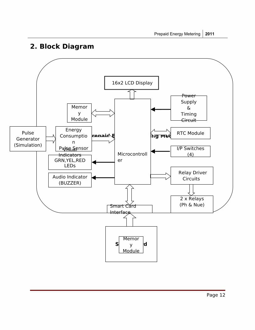
2. Block Diagram
Page 12
Prepaid Energy Metering Module
Microcontroller
Smart CardMemor
yModule
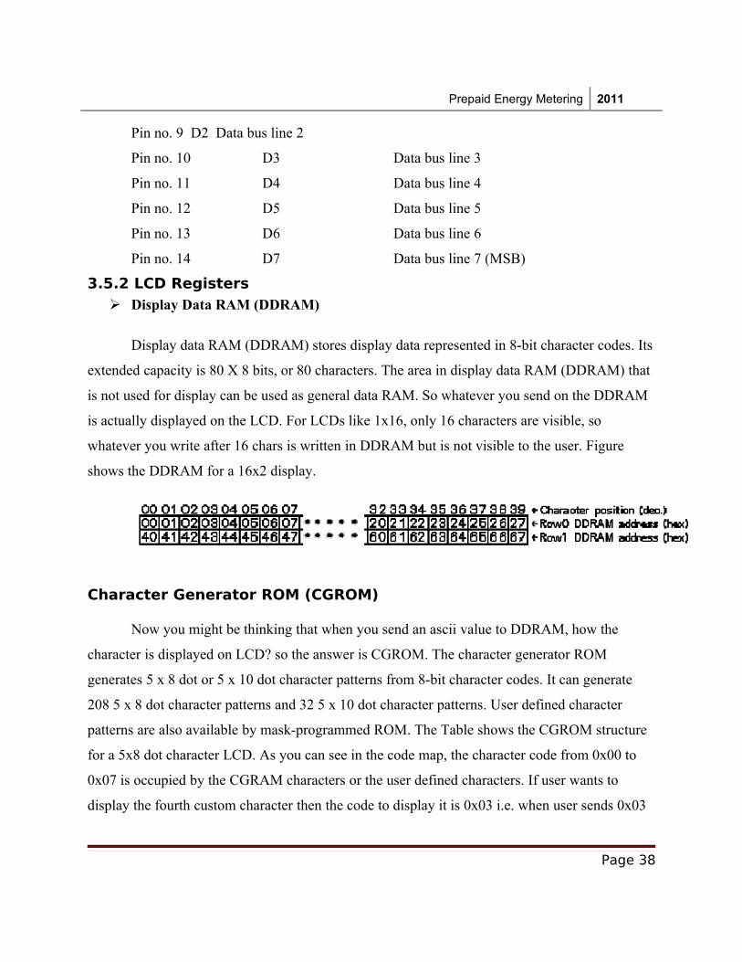
16x2 LCD Display
Relay Driver Circuits
Energy Consumptio
nPulse SensorVisual Indicators
GRN,YEL,RED LEDs
Memory
Module
Smart Card Interface
Audio Indicator(BUZZER)
2 x Relays (Ph & Nue)
RTC Module
I/P Switches (4)
Power Supply
&Timing Circuit
Pulse Generator
(Simulation)
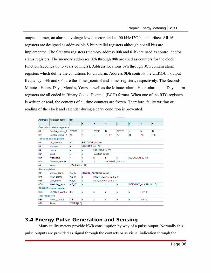
Prepaid Energy Metering 2011
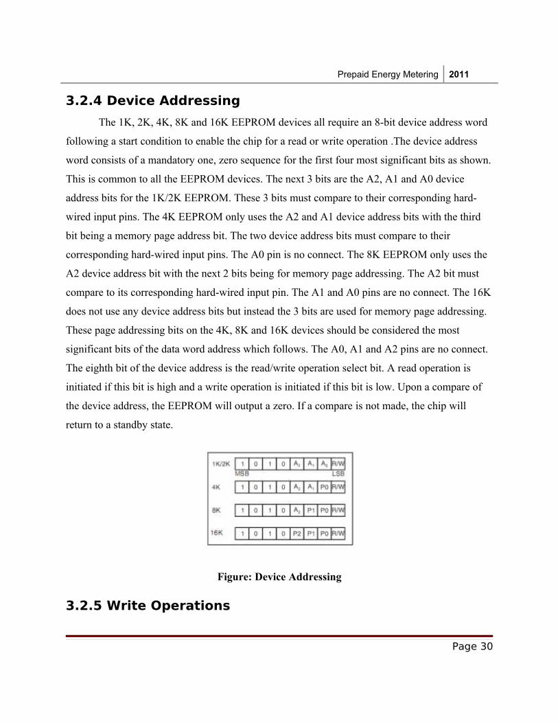
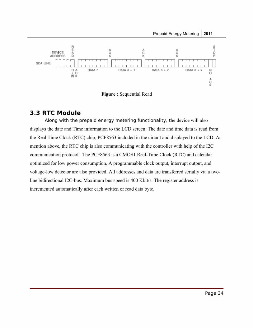
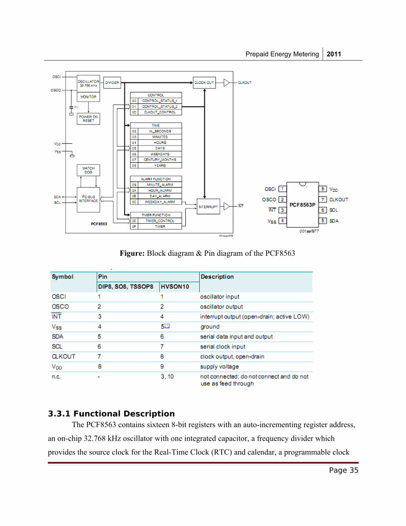
3. General Description
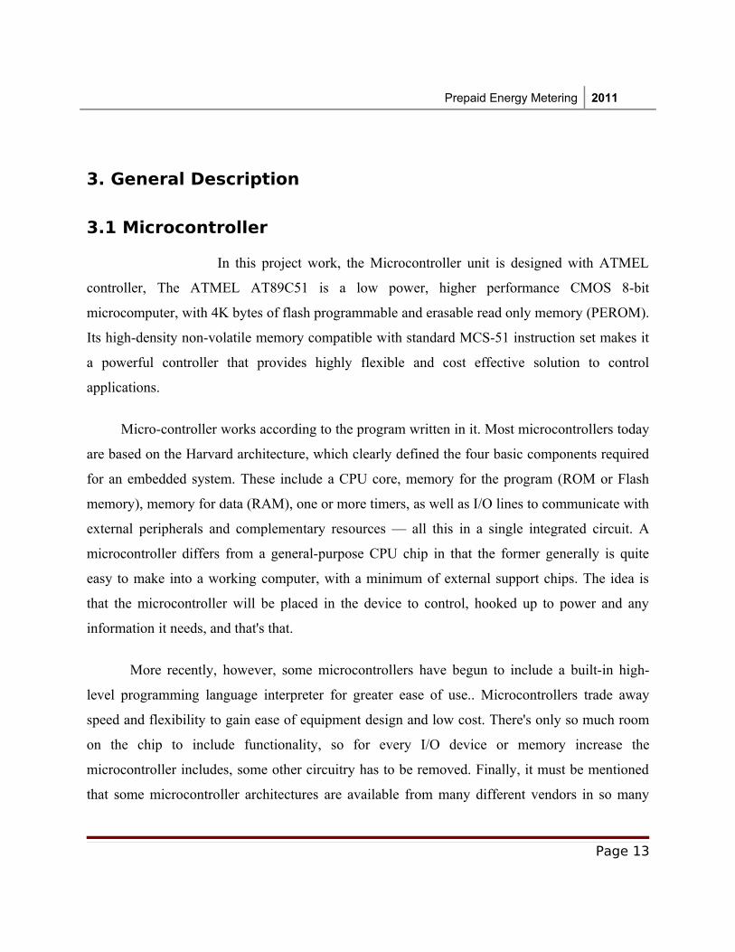
3.1 Microcontroller
In this project work, the Microcontroller unit is designed with ATMEL
controller, The ATMEL AT89C51 is a low power, higher performance CMOS 8-bit
microcomputer, with 4K bytes of flash programmable and erasable read only memory (PEROM).
Its high-density non-volatile memory compatible with standard MCS-51 instruction set makes it
a powerful controller that provides highly flexible and cost effective solution to control
applications.
Micro-controller works according to the program written in it. Most microcontrollers today
are based on the Harvard architecture, which clearly defined the four basic components required
for an embedded system. These include a CPU core, memory for the program (ROM or Flash
memory), memory for data (RAM), one or more timers, as well as I/O lines to communicate with
external peripherals and complementary resources — all this in a single integrated circuit. A
microcontroller differs from a general-purpose CPU chip in that the former generally is quite
easy to make into a working computer, with a minimum of external support chips. The idea is
that the microcontroller will be placed in the device to control, hooked up to power and any
information it needs, and that's that.
More recently, however, some microcontrollers have begun to include a built-in high-
level programming language interpreter for greater ease of use.. Microcontrollers trade away
speed and flexibility to gain ease of equipment design and low cost. There's only so much room
on the chip to include functionality, so for every I/O device or memory increase the
microcontroller includes, some other circuitry has to be removed. Finally, it must be mentioned
that some microcontroller architectures are available from many different vendors in so many
Page 13
Prepaid Energy Metering 2011
varieties that they could rightly belong to a category of their own. Chief among these are the
8051 family.
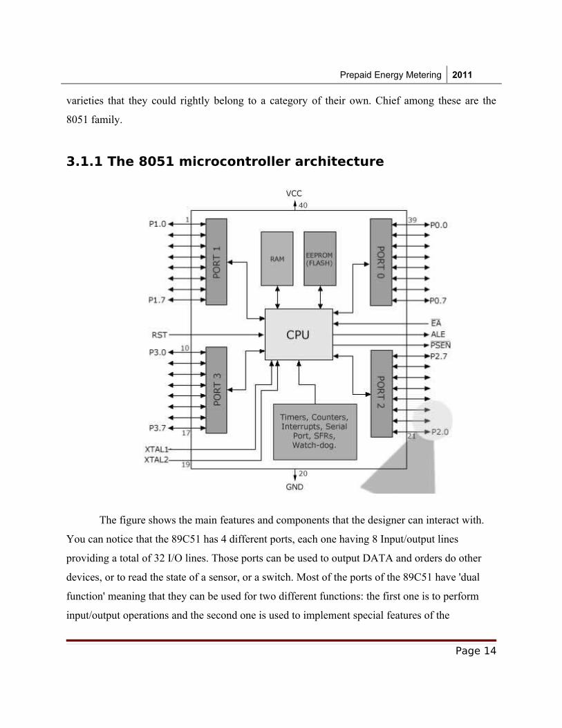
3.1.1 The 8051 microcontroller architecture
The figure shows the main features and components that the designer can interact with.
You can notice that the 89C51 has 4 different ports, each one having 8 Input/output lines
providing a total of 32 I/O lines. Those ports can be used to output DATA and orders do other
devices, or to read the state of a sensor, or a switch. Most of the ports of the 89C51 have 'dual
function' meaning that they can be used for two different functions: the first one is to perform
input/output operations and the second one is used to implement special features of the
Page 14
Prepaid Energy Metering 2011
microcontroller like counting external pulses, interrupting the execution of the program
according to external events, performing serial data transfer or connecting the chip to a computer
to update the software. Each port has 8 pins, and will be treated from the software point of view
as an 8-bit variable called 'register', each bit being connected to a different Input/output pin.
Also there 2 different memory types: RAM and EEPROM. Shortly, RAM is used to store
variable during program execution, while the EEPROM memory is used to store the program
itself, that's why it is often referred to as the 'program memory'.
89C51 incorporates hardware circuits that can be used to prevent the processor from
executing various repetitive tasks and save processing power for more complex calculations.
Those simple tasks can be counting the number of external pulses on a pin, or generating precise
timing sequences. It is clear that the CPU (Central Processing Unit) is the heart of the
microcontrollers; It is the CPU that will Read the program from the FLASH memory and execute
it by interacting with the different peripherals discussed above.
Page 15
Prepaid Energy Metering 2011
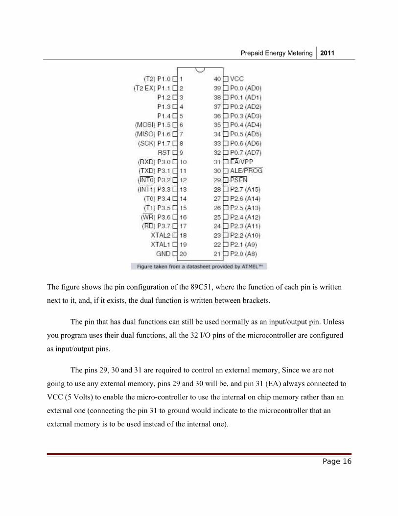
The figure shows the pin configuration of the 89C51, where the function of each pin is written
next to it, and, if it exists, the dual function is written between brackets.
The pin that has dual functions can still be used normally as an input/output pin. Unless
you program uses their dual functions, all the 32 I/O pins of the microcontroller are configured
as input/output pins.
The pins 29, 30 and 31 are required to control an external memory, Since we are not
going to use any external memory, pins 29 and 30 will be, and pin 31 (EA) always connected to
VCC (5 Volts) to enable the micro-controller to use the internal on chip memory rather than an
external one (connecting the pin 31 to ground would indicate to the microcontroller that an
external memory is to be used instead of the internal one).
Page 16
Prepaid Energy Metering 2011
3.1.2 Memory Organization
A RAM stands for Random Access Memory, it has basically the same purpose of the
RAM in a desktop computer, which is to store some data required during the execution time of
different programs. While an EEPROM, also called FLASH memory is a more elaborated ROM
(Read Only Memory) which is the memory where the program being executed is stored. Even if
that's not exactly true, you can compare an EEPROM to the Hard-Disk of a desktop computer
from a general point of view. The EEPROM term stands for Electronically Erasable and
Programmable Read Only Memory.
In microcontrollers, like in any digital system, memory is organized in Registers, Which
is the basic unit of construction of a memory. Each register is composed of a number of bits
(usually 8) where the data can be stored. In the 8051 family of microcontrollers for example,
most registers are 8-bit register, capable of storing values ranging from 0 to 255. In order to use
bigger values, various register can be used simultaneously.
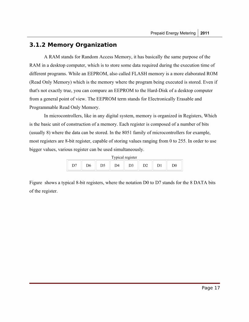
Typical register
D7 D6 D5 D4 D3 D2 D1 D0
Figure shows a typical 8-bit registers, where the notation D0 to D7 stands for the 8 DATA bits
of the register.
Page 17
Prepaid Energy Metering 2011
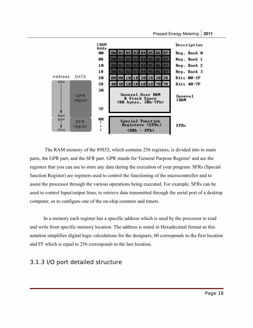
The RAM memory of the 89S52, which contains 256 registers, is divided into to main
parts, the GPR part, and the SFR part. GPR stands for 'General Purpose Register' and are the
registers that you can use to store any data during the execution of your program. SFRs (Special
function Register) are registers used to control the functioning of the microcontroller and to
assist the processor through the various operations being executed. For example, SFRs can be
used to control Input/output lines, to retrieve data transmitted through the serial port of a desktop
computer, or to configure one of the on-chip counters and timers.
In a memory each register has a specific address which is used by the processor to read
and write from specific memory location. The address is noted in Hexadecimal format as this
notation simplifies digital logic calculations for the designers, 00 corresponds to the first location
and FF which is equal to 256 corresponds to the last location.
3.1.3 I/O port detailed structure
Page 18
Prepaid Energy Metering 2011
It is important to have some basic notions about the structure of an I/O port in the 8051
architecture. Actually, the I/O ports configuration and mechanism of the 8051 can be confusing,
due to the fact that a pin acts as an output pin as well as an input pin in the same time.
Page 19
Prepaid Energy Metering 2011
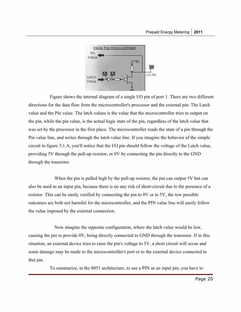
Figure shows the internal diagram of a single I/O pin of port 1. There are two different
directions for the data flow from the microcontroller's processor and the external pin: The Latch
value and the Pin value. The latch values is the value that the microcontroller tries to output on
the pin, while the pin value, is the actual logic state of the pin, regardless of the latch value that
was set by the processor in the first place. The microcontroller reads the state of a pin through the
Pin value line, and writes through the latch value line. If you imagine the behavior of the simple
circuit in figure 3.1.A, you'll notice that the I/O pin should follow the voltage of the Latch value,
providing 5V through the pull-up resistor, or 0V by connecting the pin directly to the GND
through the transistor.
When the pin is pulled high by the pull-up resistor, the pin can output 5V but can
also be used as an input pin, because there is no any risk of short-circuit due to the presence of a
resistor. This can be easily verified by connecting the pin to 0V or to 5V, the tow possible
outcomes are both not harmful for the microcontroller, and the PIN value line will easily follow
the value imposed by the external connection.
Now imagine the opposite configuration, where the latch value would be low,
causing the pin to provide 0V, being directly connected to GND through the transistor. If in this
situation, an external device tries to raise the pin's voltage to 5V, a short circuit will occur and
some damage may be made to the microcontroller's port or to the external device connected to
that pin.
To summarize, in the 8051 architecture, to use a PIN as an input pin, you have to
Page 20
Prepaid Energy Metering 2011
output '1', and the pin value will follow the value imposed by the device connected to it (switch,
sensor, etc...). If you plan to use the pin as an output pin, then just output the required value
without taking any of this in consideration. Even if some ports like P3 and P0 can have a slightly
different internal composition than P1, due to the dual functions they assure, understanding the
structure and functioning of port 1 as described above is fairly enough to use all the ports for
basic I/O operations.
3.1.4 Introduction to 89C51 Peripherals
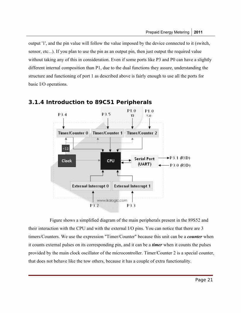
Figure shows a simplified diagram of the main peripherals present in the 89S52 and
their interaction with the CPU and with the external I/O pins. You can notice that there are 3
timers/Counters. We use the expression "Timer/Counter" because this unit can be a counter when
it counts external pulses on its corresponding pin, and it can be a timer when it counts the pulses
provided by the main clock oscillator of the microcontroller. Timer/Counter 2 is a special counter,
that does not behave like the tow others, because it has a couple of extra functionality.
Page 21
Prepaid Energy Metering 2011
The serial port, using a UART (Universal Asynchronous Receive Transmit) protocol
can be used in a wide range of communication applications. With the UART provided in the
89S52 you can easily communicate with a serial port equipped computer, as well as communicate
with another microcontroller. This last application, called Multi-processor communication, is
quite interesting, and can be easily implemented with 2 89S52 microcontrollers to build a very
powerful multi-processor controllers.
If all the peripherals described above can generate interrupt signals in the CPU
according to some specific events, it can be useful to generate an interrupt signal from an external
device, that may be a sensor or a Digital to Analog converter. For that purpose there are 2
External Interrupt sources (INT0 and INT1).
3.1.5 External Interrupts Let's start with the simplest peripheral which is the external interrupt, which can be
used to cause interruptions on external events (a pin changing its state from 0 to 1 or vice-versa).
In case you don't know, interruption is a mean of stopping the flow of a program, as a response to
a certain event, to execute a small program called 'interrupt routine'. As you noticed in figure, in
the 89S52, there are two external interrupt sources, one connected to the pin P3.2 and the other to
P3.3. They are configured using a number of SFRs (Special Function Registers). Most of those
SFRs are shared by other peripherals as you shall see in the rest of the tutorial.
The IE register
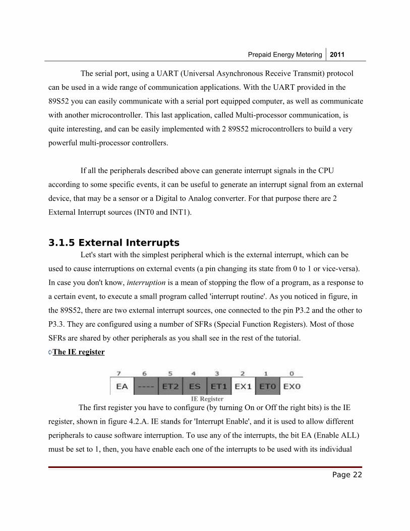
IE Register The first register you have to configure (by turning On or Off the right bits) is the IE
register, shown in figure 4.2.A. IE stands for 'Interrupt Enable', and it is used to allow different
peripherals to cause software interruption. To use any of the interrupts, the bit EA (Enable ALL)
must be set to 1, then, you have enable each one of the interrupts to be used with its individual
Page 22
Prepaid Energy Metering 2011
enable bit. For the external interrupts, the two bits EX0 and EX1 are used for External Interrupt 0
and External Interrupt 1.
Using the C programming language under KEIL, it is extremely simple to set those bits, simply
by using their name as any global variables, Using the following syntax:
EA = 1;
EX0 = 1;
EX1 = 1;
The rest of the bits of IE register are used for other interrupt sources like the 3 timers overflow
(ETx) and the serial interface (ES).
The TCON register
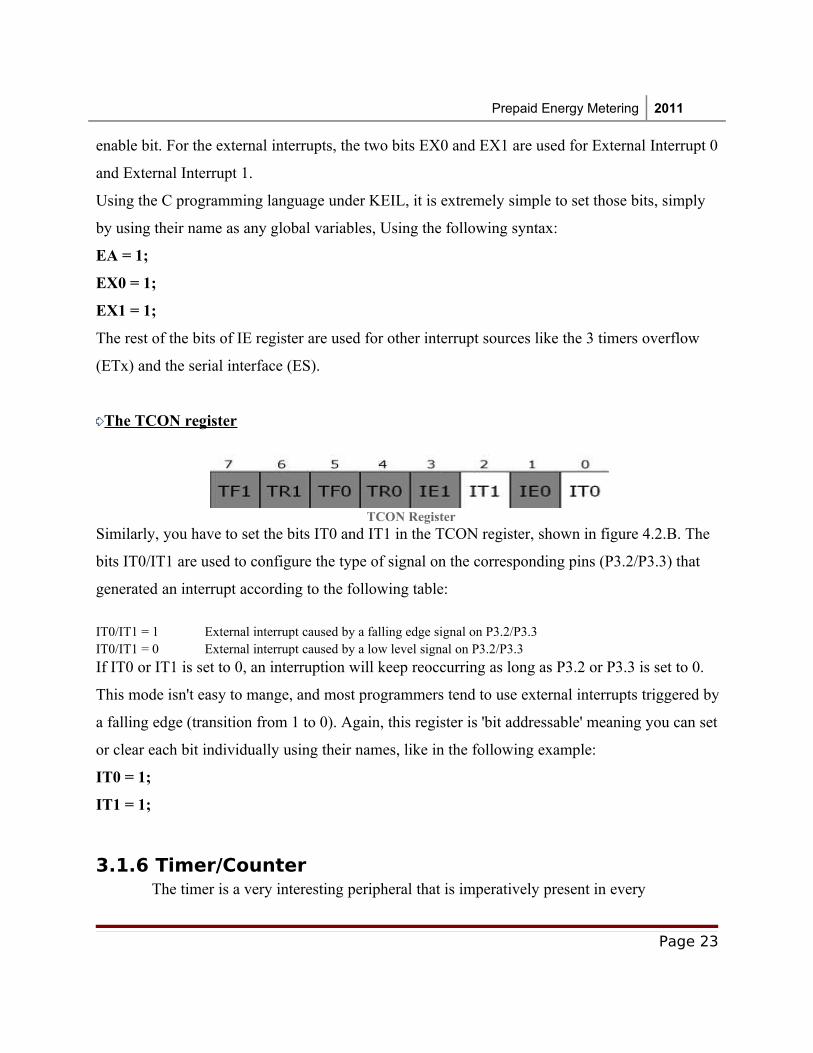
TCON RegisterSimilarly, you have to set the bits IT0 and IT1 in the TCON register, shown in figure 4.2.B. The
bits IT0/IT1 are used to configure the type of signal on the corresponding pins (P3.2/P3.3) that
generated an interrupt according to the following table:
IT0/IT1 = 1 External interrupt caused by a falling edge signal on P3.2/P3.3IT0/IT1 = 0 External interrupt caused by a low level signal on P3.2/P3.3
If IT0 or IT1 is set to 0, an interruption will keep reoccurring as long as P3.2 or P3.3 is set to 0.
This mode isn't easy to mange, and most programmers tend to use external interrupts triggered by
a falling edge (transition from 1 to 0). Again, this register is 'bit addressable' meaning you can set
or clear each bit individually using their names, like in the following example:
IT0 = 1;
IT1 = 1;
3.1.6 Timer/Counter The timer is a very interesting peripheral that is imperatively present in every
Page 23
Prepaid Energy Metering 2011
microcontroller. It can be used in tow distinct modes:
Timer: Counting internal clock pulses, which are fixed with time, hence, we can say that it is
very precise timer, whose resolution depends on the frequency of the main CPU clock (note that
CPU clock equals the crystal frequency over 12).
Counter: Counting external pulses (on the corresponding I/O pin), which can be provided by a
rotational encoder, an IR-barrier sensor, or any device that provide pulses, whose number would
be of some interest.
Sure, the CPU of a microcontroller could provide the required timing or counting, but
the timer/counter peripheral relieves the CPU from that redundant and repetitive task, allowing it
to allocate maximum processing power for more complex calculations.
So, like any other peripheral, a Timer/Counter can ask for an interruption of the program, which -
if enabled - occurs when the counting registers of the Timer/Counter are full and overflow. More
precisely, the interruption will occur at the same time the counting register will be reinitialized to
its initial value.
So to control the behavior of the timers/counters, a set of SFR are used, most of them have
already been seen at the top of this tutorial.
The IE register
First, you have to Enable the corresponding interrupts, but writing 1's to the
corresponding bits in the IE register. The following table shows the names and definitions of the
concerned bits of the IR register .
EA Enable All interruptsET2 Enable Timer 2 interrupts (will not be treated in this tutorial)ET1 Enable Timer 1 interruptsET0 Enable Timer 0 interrupts
You can access those special bits by their names, as simply as it seems, example:
ET0 = 1;
The TCON register
Page 24
Prepaid Energy Metering 2011
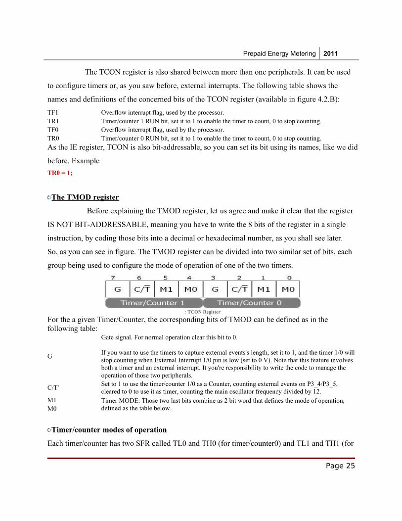
The TCON register is also shared between more than one peripherals. It can be used
to configure timers or, as you saw before, external interrupts. The following table shows the
names and definitions of the concerned bits of the TCON register (available in figure 4.2.B):
TF1 Overflow interrupt flag, used by the processor.TR1 Timer/counter 1 RUN bit, set it to 1 to enable the timer to count, 0 to stop counting.TF0 Overflow interrupt flag, used by the processor.TR0 Timer/counter 0 RUN bit, set it to 1 to enable the timer to count, 0 to stop counting.
As the IE register, TCON is also bit-addressable, so you can set its bit using its names, like we did
before. Example
TR0 = 1;
The TMOD register
Before explaining the TMOD register, let us agree and make it clear that the register
IS NOT BIT-ADDRESSABLE, meaning you have to write the 8 bits of the register in a single
instruction, by coding those bits into a decimal or hexadecimal number, as you shall see later.
So, as you can see in figure. The TMOD register can be divided into two similar set of bits, each
group being used to configure the mode of operation of one of the two timers.
: TCON Register
For the a given Timer/Counter, the corresponding bits of TMOD can be defined as in the following table:
G
Gate signal. For normal operation clear this bit to 0.
If you want to use the timers to capture external events's length, set it to 1, and the timer 1/0 will stop counting when External Interrupt 1/0 pin is low (set to 0 V). Note that this feature involves both a timer and an external interrupt, It you're responsibility to write the code to manage the operation of those two peripherals.
C/T'Set to 1 to use the timer/counter 1/0 as a Counter, counting external events on P3_4/P3_5, cleared to 0 to use it as timer, counting the main oscillator frequency divided by 12.
M1 Timer MODE: Those two last bits combine as 2 bit word that defines the mode of operation, defined as the table below. M0
Timer/counter modes of operation
Each timer/counter has two SFR called TL0 and TH0 (for timer/counter0) and TL1 and TH1 (for
Page 25
Prepaid Energy Metering 2011
timer/counter 1). TL stands for timer LOW, and is used to store the lower bits of the number
being counted by the timer/counter. TH stands for TH, and is used to store the higher bits of the
number being counted by the timer/counter.
M1 M0 Mode Description
0 0 0
Only TH0/1 is used, forming an 8bit timer/counter.Timer/counter will count up from the value initially stored in TH0/1 to 255, and then overflow
back to 0. If an interrupt is enabled, an interrupt will occur upon overflow.If used as timer, pulses from the processor are divided by 32 (after being divided by 12). The
result is the main oscillator frequency divided by 384. If used as counter, external pulses are only divided by 32.
0 1 1
Both TH0/1 and TL0/1 are used, forming a 16 bit timer/counter.Timer/counter will count up from the 16 bit value initially stored in TH0/1 and TL0/1 to
65535, and then overflow back to 0. If an interrupt is enabled, an interrupt will occur upon overflow.If used as timer, pulses from the processor are only divided by 12.If used as counter, external pulses are not divided, but the maximum frequency that can be
accurately counted equals the oscillator frequency divided by 24.
1 0 2
TL0/1 is used for counting, forming an 8 bit timer/counter. TH0/1 is used to hold the value to be restored in TL upon overflow.
Timer/counter will count up from the 8 bit value initially stored in TL0/1 and to 255, and then overflow, setting the value of TH0/1 in TL0/1. This is called the auto-reload function.
If an interrupt is enabled, an interrupt will occur upon overflow.If used as timer, pulses from the processor are only divided by 12.If used as counter, external pulses are not divided, but the maximum frequency that can be
accurately counted equals the oscillator frequency divided by 24.
1 1 3 This mode is beyond the scope of this tutorial.
Timer modes 1 and 2 are the most used in 8051 microcontroller projects, since they offer a wide
range of possible customizations.
3.2 Memory Modules In this project, the microcontroller is interfaced with two memory modules. One for
storing the setting details, tariff details and balance amount s etc. and the second memory is
included in the smart card which holds the recharge amount. Once the smart card is detected, the
controller checks the memory for its validity, and if it’s a valid card the amount is read from the
memory location and adds and store into the built in memory’s balance amount location. Once
the amount is read from the smart card memory, the controller will erase the memory part and
make it invalid for further reusing.
Page 26
Prepaid Energy Metering 2011
The memory modules are built upon the serial eeprom chips AT24Cxx series, and
communicate with the controller with the help of I2C protocol. The AT24C01/02/04/08/16
provides 1024/2048/4096/8192/16384 bits of serial electrically erasable and programmable read-
only memory (EEPROM) organized as 128/256/512/1024/2048 words of 8 bits each. The device
is optimized for use in many industrial and commercial applications where low-power and low-
voltage operation are essential. The AT24C01/02/04/08/16 is available in space-saving 8-lead
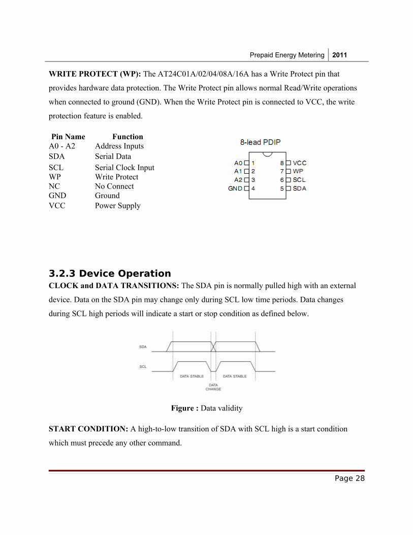
The relay driver is used to drive the relay that is used in the circuit. The relay act similar
to the hook switch in the normal phone. When then line is in idle mode, the relay will be in OFF
state which is similar to the ON-Hook in the Phones. In On-hook state, through the relay path the
telephone line is connected to the ring indicator circuit. When a ring occurs, the ring indicator
will interrupt the controller and the controller will send a signal to the relay driver, for driving
the relay. The driving of the relay to the ON state will change the device to the OFF-hook state
and the call will be connected.
3.6.1 Relay Basics
Page 41
Prepaid Energy Metering 2011
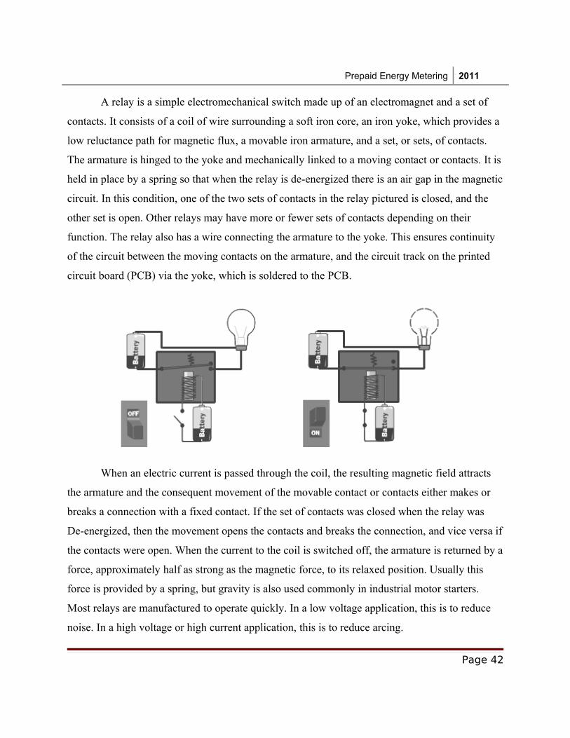
A relay is a simple electromechanical switch made up of an electromagnet and a set of
contacts. It consists of a coil of wire surrounding a soft iron core, an iron yoke, which provides a
low reluctance path for magnetic flux, a movable iron armature, and a set, or sets, of contacts.
The armature is hinged to the yoke and mechanically linked to a moving contact or contacts. It is
held in place by a spring so that when the relay is de-energized there is an air gap in the magnetic
circuit. In this condition, one of the two sets of contacts in the relay pictured is closed, and the
other set is open. Other relays may have more or fewer sets of contacts depending on their
function. The relay also has a wire connecting the armature to the yoke. This ensures continuity
of the circuit between the moving contacts on the armature, and the circuit track on the printed
circuit board (PCB) via the yoke, which is soldered to the PCB.
When an electric current is passed through the coil, the resulting magnetic field attracts
the armature and the consequent movement of the movable contact or contacts either makes or
breaks a connection with a fixed contact. If the set of contacts was closed when the relay was
De-energized, then the movement opens the contacts and breaks the connection, and vice versa if
the contacts were open. When the current to the coil is switched off, the armature is returned by a
force, approximately half as strong as the magnetic force, to its relaxed position. Usually this
force is provided by a spring, but gravity is also used commonly in industrial motor starters.
Most relays are manufactured to operate quickly. In a low voltage application, this is to reduce
noise. In a high voltage or high current application, this is to reduce arcing.
Page 42
Prepaid Energy Metering 2011
If the coil is energized with DC, a diode is frequently installed across the coil, to dissipate
the energy from the collapsing magnetic field at deactivation, which would otherwise generate a
voltage spike dangerous to circuit components. Some automotive relays already include a diode
inside the relay case. Alternatively a contact protection network, consisting of a capacitor and
resistor in series, may absorb the surge. If the coil is designed to be energized with AC, a small
copper ring can be crimped to the end of the solenoid. This "shading ring" creates a small out-of-
phase current, which increases the minimum pull on the armature during the AC cycle.
3.7 Power Supply and timing signals
The whole circuit works on the 5V, DC power. A transformer based power supply is used
in this project, to step down the direct 230V AC to 9VAC. The step downed voltage is applied to
the rectifier circuit which will convert the AC to DC. An electrolyte capacitor will act as a filter
for smoothening the dc. The popular 5V regulator, LM7805 is used for regulate the 9VDC to
5VDC.
Page 43
Prepaid Energy Metering 2011
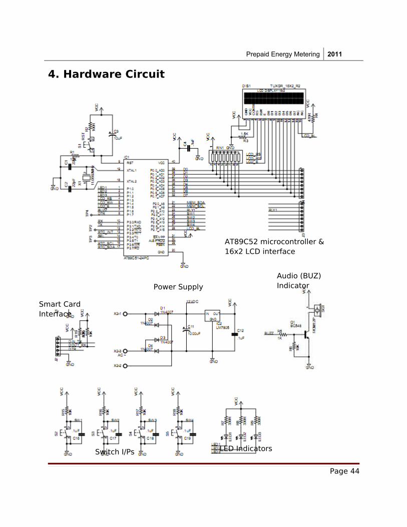
4. Hardware Circuit
Page 44
AT89C52 microcontroller &16x2 LCD interface
Smart Card Interface
Power Supply
Audio (BUZ) Indicator
Switch I/Ps LED Indicators
Prepaid Energy Metering 2011
Page 45
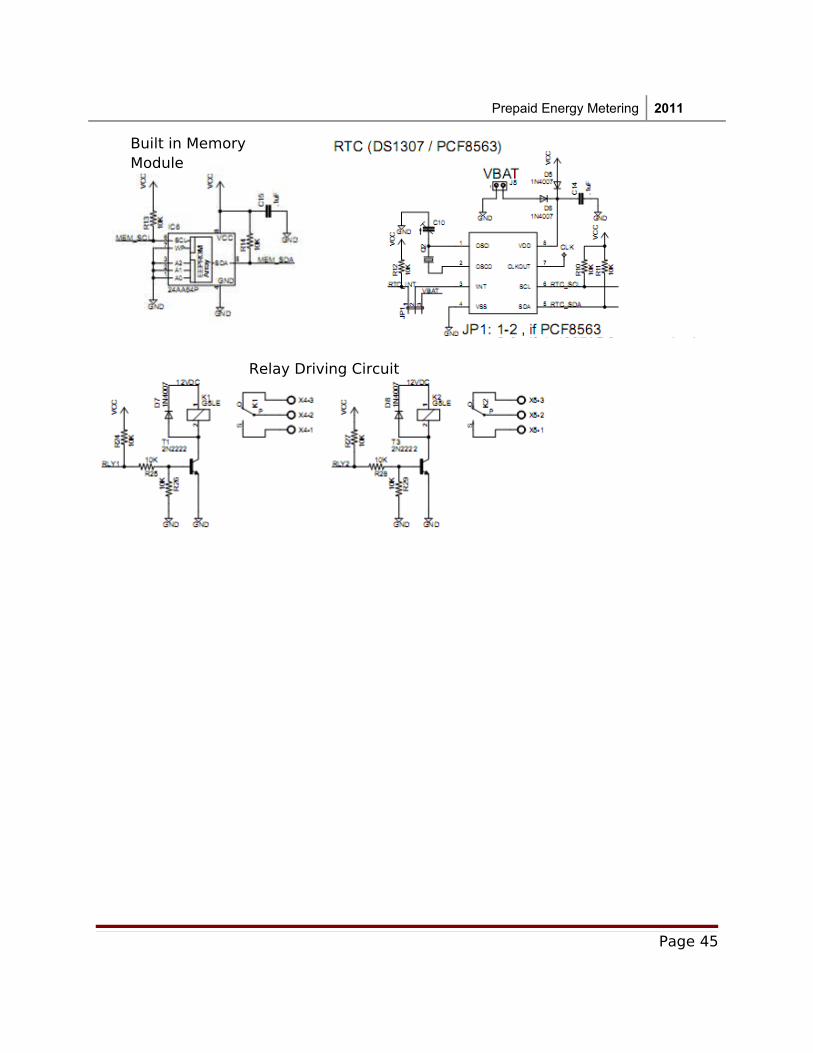
Built in Memory Module
Relay Driving Circuit
Prepaid Energy Metering 2011
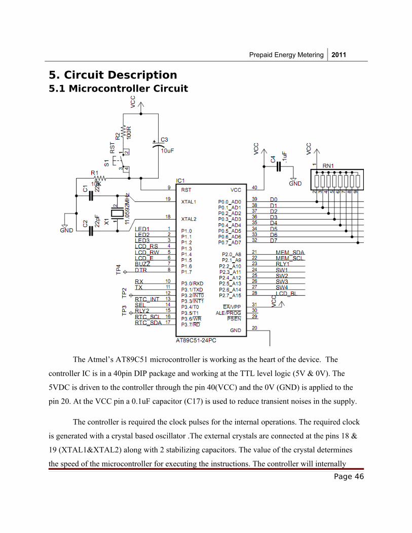
5. Circuit Description5.1 Microcontroller Circuit
The Atmel’s AT89C51 microcontroller is working as the heart of the device. The
controller IC is in a 40pin DIP package and working at the TTL level logic (5V & 0V). The
5VDC is driven to the controller through the pin 40(VCC) and the 0V (GND) is applied to the
pin 20. At the VCC pin a 0.1uF capacitor (C17) is used to reduce transient noises in the supply.
The controller is required the clock pulses for the internal operations. The required clock
is generated with a crystal based oscillator .The external crystals are connected at the pins 18 &
19 (XTAL1&XTAL2) along with 2 stabilizing capacitors. The value of the crystal determines
the speed of the microcontroller for executing the instructions. The controller will internally
Page 46
Prepaid Energy Metering 2011
divide the crystal’s clock frequency that we are applying by 12 to generate a machine cycle. If
the crystal connected is 12 MHz, the machine cycle will at 1MHz frequency, which means 1
machine cycle will take 1usec time. In our circuit we are using the 11.0592MHz crystal. There
the internal frequency divider will generate a 921.6 KHz for the machine cycle (1.085usec). We
selected the 11.0592MHz for generating the exact baud rate for the serial communication.
The EA on pin 31 is tied high to make the 8051 executes program from Internal Rom.
PIN 9; the RESET pin is an active High input. When RESET is set to High, 8051 goes back to
the power on state. The 8051 is reset by holding the RST high for at least two machine cycles
and then returning it low. After a reset, the program counter is loaded with 0000H but the content
of on-chip RAM is not affected. The value of the capacitor and resistor determine the time to
hold the RESET pin in high state.
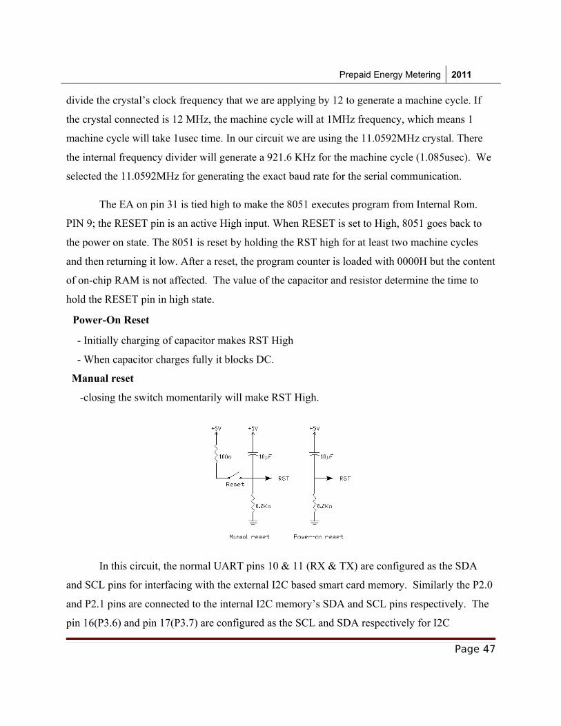
Power-On Reset
- Initially charging of capacitor makes RST High
- When capacitor charges fully it blocks DC.
Manual reset
-closing the switch momentarily will make RST High.
In this circuit, the normal UART pins 10 & 11 (RX & TX) are configured as the SDA
and SCL pins for interfacing with the external I2C based smart card memory. Similarly the P2.0
and P2.1 pins are connected to the internal I2C memory’s SDA and SCL pins respectively. The
pin 16(P3.6) and pin 17(P3.7) are configured as the SCL and SDA respectively for I2C
Page 47
Prepaid Energy Metering 2011
interfacing with the RTC chip PCF8563. All these pins are pulled up to the VCC line through
10K resistors. The Smart Card line I2C only required activating when a card is inserted to the
card slot. For detecting the presence of the smart card the microcontroller’s P1.7 pin is used.
Once the smartcard is inserted, this line is connected to the GND through the card’s circuit and
by sensing the logic level at this pin; the controller can detect the presence of the smart card.
The P0 port (pin 39-32) is connected to the LCD display. It acts the data lines to the LCD
(D0-D7). The P0.7 (pin 32) is also used for the sensing the BUSY flag from the LCD display.
The LCD display requires three control lines. The microcontroller’s port pins P1.3 - P1.5 for the
purpose. P1.5 drives the Enable pin of the LCD. P1.4 is used for the R/W operations and P1.3 is
for connected to the RS pin for selecting the Command / data register in the display controller.
Since the P0 doesn’t contains the internal pull resistors, an external array of 10K resistors are
connected to the pins.
The port pin P1.6 is connected to the base of the NPN transistor Q1 through a 1K resistor.
This pin is used for creating the beep sound from the buzzer. Pin 15(P3.5) and Pin 23(P2.2) are
driven to the relay driving circuit used for controlling the relays. The pin 12 is used for getting
the signal from the Pulse Generator circuit. Since this pin can configure for the interrupt services,
a High to Low transition in the voltage connected to the pin will interrupt the controller from its
current process routine. The Port pins P2.3 – P2.6 are configured as the input pins and interfaced
to the 4 switches. By sensing a low logic level on each pin, the controller can sense the
corresponding key press. The P1.0 – P1.2 pins are connected to the Green, Yellow, and Red Leds
for the visual indications.
Page 48
Prepaid Energy Metering 2011
5.2 LCD Display
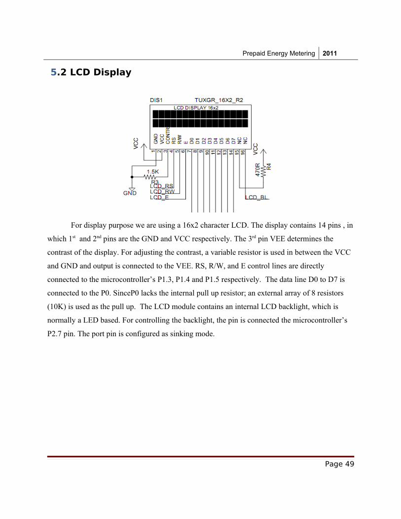
For display purpose we are using a 16x2 character LCD. The display contains 14 pins , in
which 1st and 2nd pins are the GND and VCC respectively. The 3rd pin VEE determines the
contrast of the display. For adjusting the contrast, a variable resistor is used in between the VCC
and GND and output is connected to the VEE. RS, R/W, and E control lines are directly
connected to the microcontroller’s P1.3, P1.4 and P1.5 respectively. The data line D0 to D7 is
connected to the P0. SinceP0 lacks the internal pull up resistor; an external array of 8 resistors
(10K) is used as the pull up. The LCD module contains an internal LCD backlight, which is
normally a LED based. For controlling the backlight, the pin is connected the microcontroller’s
P2.7 pin. The port pin is configured as sinking mode.
Page 49
Prepaid Energy Metering 2011
5.3 Memory chip Interfacing
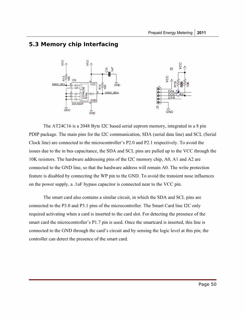
The AT24C16 is a 2048 Byte I2C based serial eeprom memory, integrated in a 8 pin
PDIP package. The main pins for the I2C communication, SDA (serial data line) and SCL (Serial
Clock line) are connected to the microcontroller’s P2.0 and P2.1 respectively. To avoid the
issues due to the in bus capacitance, the SDA and SCL pins are pulled up to the VCC through the
10K resistors. The hardware addressing pins of the I2C memory chip, A0, A1 and A2 are
connected to the GND line, so that the hardware address will remain A0. The write protection
feature is disabled by connecting the WP pin to the GND. To avoid the transient nose influences
on the power supply, a .1uF bypass capacitor is connected near to the VCC pin.
The smart card also contains a similar circuit, in which the SDA and SCL pins are
connected to the P3.0 and P3.1 pins of the microcontroller. The Smart Card line I2C only
required activating when a card is inserted to the card slot. For detecting the presence of the
smart card the microcontroller’s P1.7 pin is used. Once the smartcard is inserted, this line is
connected to the GND through the card’s circuit and by sensing the logic level at this pin; the
controller can detect the presence of the smart card.
Page 50
Prepaid Energy Metering 2011
5.4 RTC interfacing
.
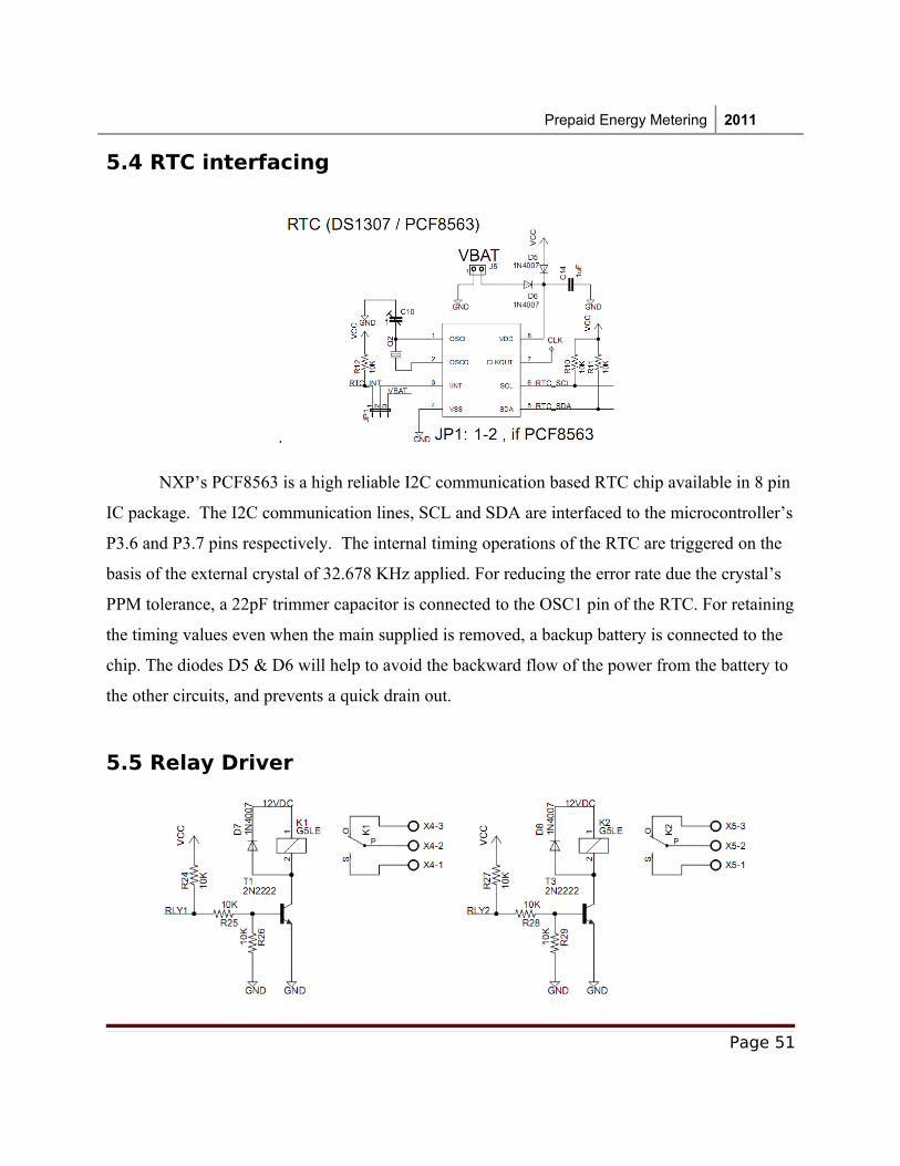
NXP’s PCF8563 is a high reliable I2C communication based RTC chip available in 8 pin
IC package. The I2C communication lines, SCL and SDA are interfaced to the microcontroller’s
P3.6 and P3.7 pins respectively. The internal timing operations of the RTC are triggered on the
basis of the external crystal of 32.678 KHz applied. For reducing the error rate due the crystal’s
PPM tolerance, a 22pF trimmer capacitor is connected to the OSC1 pin of the RTC. For retaining
the timing values even when the main supplied is removed, a backup battery is connected to the
chip. The diodes D5 & D6 will help to avoid the backward flow of the power from the battery to
the other circuits, and prevents a quick drain out.
5.5 Relay Driver
Page 51
Prepaid Energy Metering 2011
The system contains 2 relays for controlling the phase and neutral lines. The relay driver
circuit is designed by using 2 NPN transistors 2N2222. When the port PIN is high, the transistor
T1 & T3 will be in ON state, lead the energizing of the relay coil. Since the relay contains an
inductor part, switching ON/OFF will generated a back emf across it and it can spoil the
transistor. For protecting it from the back emf, a fly back diode is connected in reverse bias
across the relay’s coil.
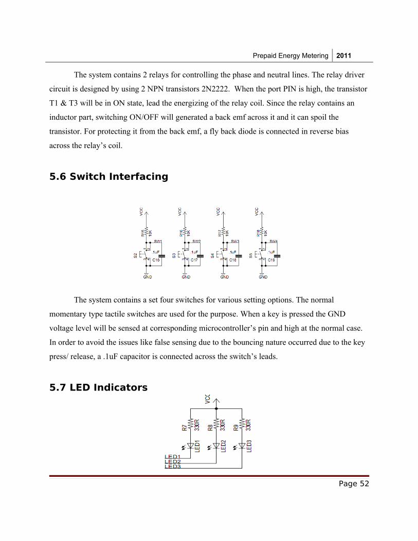
5.6 Switch Interfacing
The system contains a set four switches for various setting options. The normal
momentary type tactile switches are used for the purpose. When a key is pressed the GND
voltage level will be sensed at corresponding microcontroller’s pin and high at the normal case.
In order to avoid the issues like false sensing due to the bouncing nature occurred due to the key
press/ release, a .1uF capacitor is connected across the switch’s leads.
5.7 LED Indicators
Page 52
Prepaid Energy Metering 2011
Three LEDs are connected to the microcontrollers port pins P1.0 – P1.2 for the visual indication purposes. In the circuit the LEDs are connected in the current sinking mode. For limiting the current flow through the LED, a 330R resistor is connected to the each line.
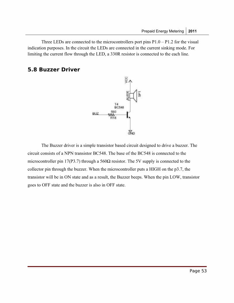
5.8 Buzzer Driver
The Buzzer driver is a simple transistor based circuit designed to drive a buzzer. The
circuit consists of a NPN transistor BC548. The base of the BC548 is connected to the
microcontroller pin 17(P3.7) through a 560Ω resistor. The 5V supply is connected to the
collector pin through the buzzer. When the microcontroller puts a HIGH on the p3.7, the
transistor will be in ON state and as a result, the Buzzer beeps. When the pin LOW, transistor
goes to OFF state and the buzzer is also in OFF state.
Page 53
Prepaid Energy Metering 2011
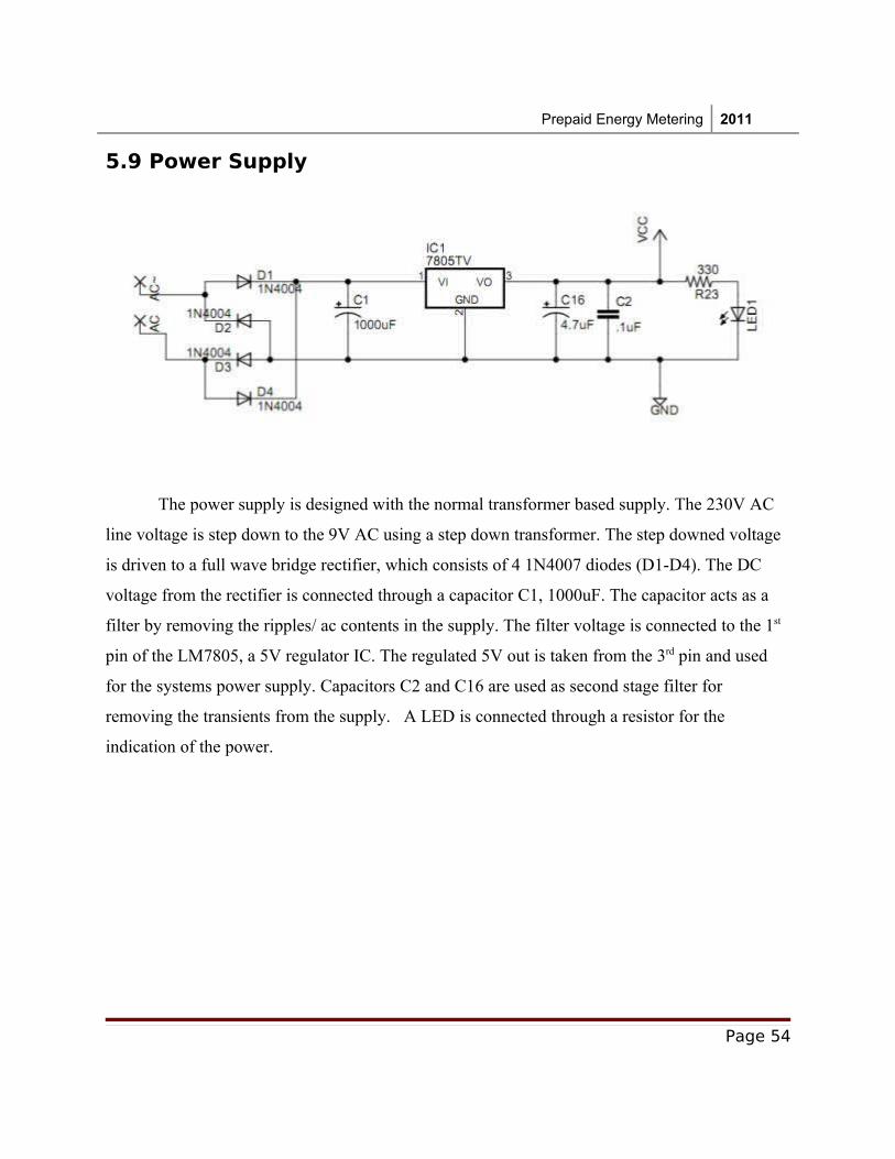
5.9 Power Supply
The power supply is designed with the normal transformer based supply. The 230V AC
line voltage is step down to the 9V AC using a step down transformer. The step downed voltage
is driven to a full wave bridge rectifier, which consists of 4 1N4007 diodes (D1-D4). The DC
voltage from the rectifier is connected through a capacitor C1, 1000uF. The capacitor acts as a
filter by removing the ripples/ ac contents in the supply. The filter voltage is connected to the 1st
pin of the LM7805, a 5V regulator IC. The regulated 5V out is taken from the 3rd pin and used
for the systems power supply. Capacitors C2 and C16 are used as second stage filter for
removing the transients from the supply. A LED is connected through a resistor for the
indication of the power.
Page 54
Prepaid Energy Metering 2011
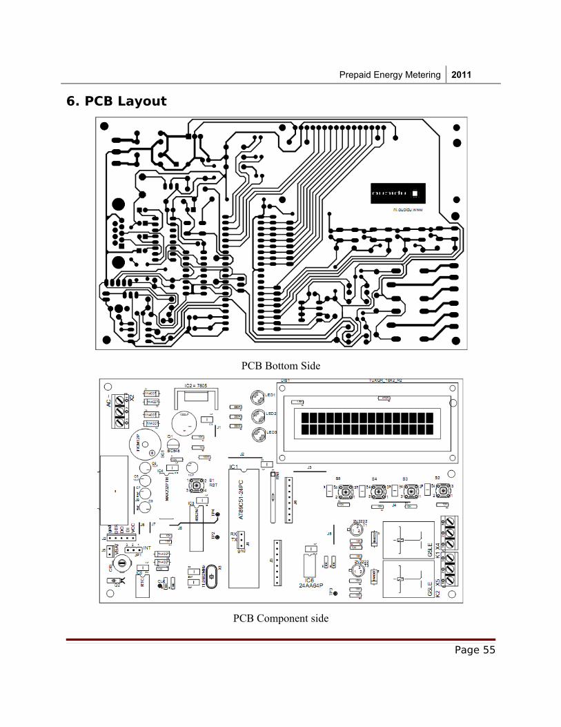
6. PCB Layout
PCB Bottom Side
PCB Component side
Page 55
Prepaid Energy Metering 2011
7. Software Description
A firmware developed in C language is programmed into the microcontroller’s code
memory area. The firmware control’s the working of the entire hardware part. Usually the
microcontrollers and the processors execute their instructions which are in machine code. In
early days the applications were written in assembly language. The development of the huge
application is very difficult by using the normal assembly language, because of their less
readability. Later for the fast developments, the high level languages are introduced into the
embedded system. C language is one of the most commonly used in the embedded system field.
The ANSI C version is modified by adding specific hardware related functionality and
information. The modified C language is commonly termed as Embedded C. The Keil Uvision 3
IDE is used for the development of the embedded system application development.
Page 56
Prepaid Energy Metering 2011
7.1 Flowchart
Page 57
Prepaid Energy Metering 2011
Page 58
Prepaid Energy Metering 2011
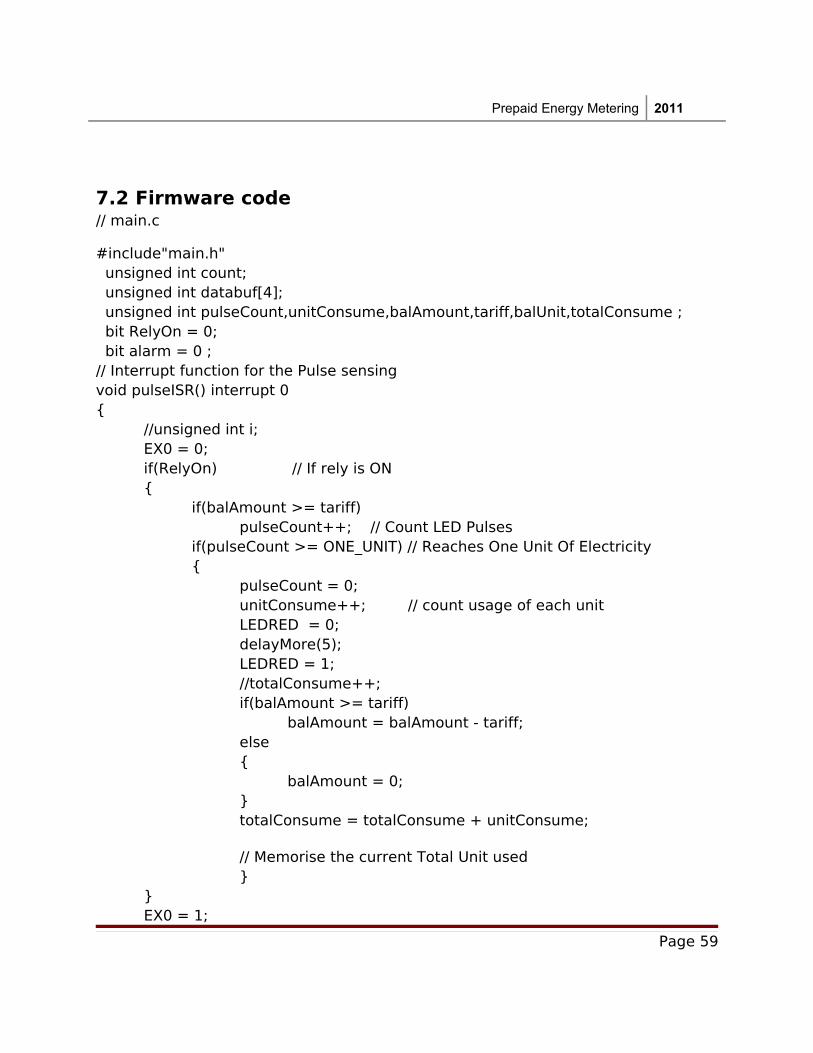
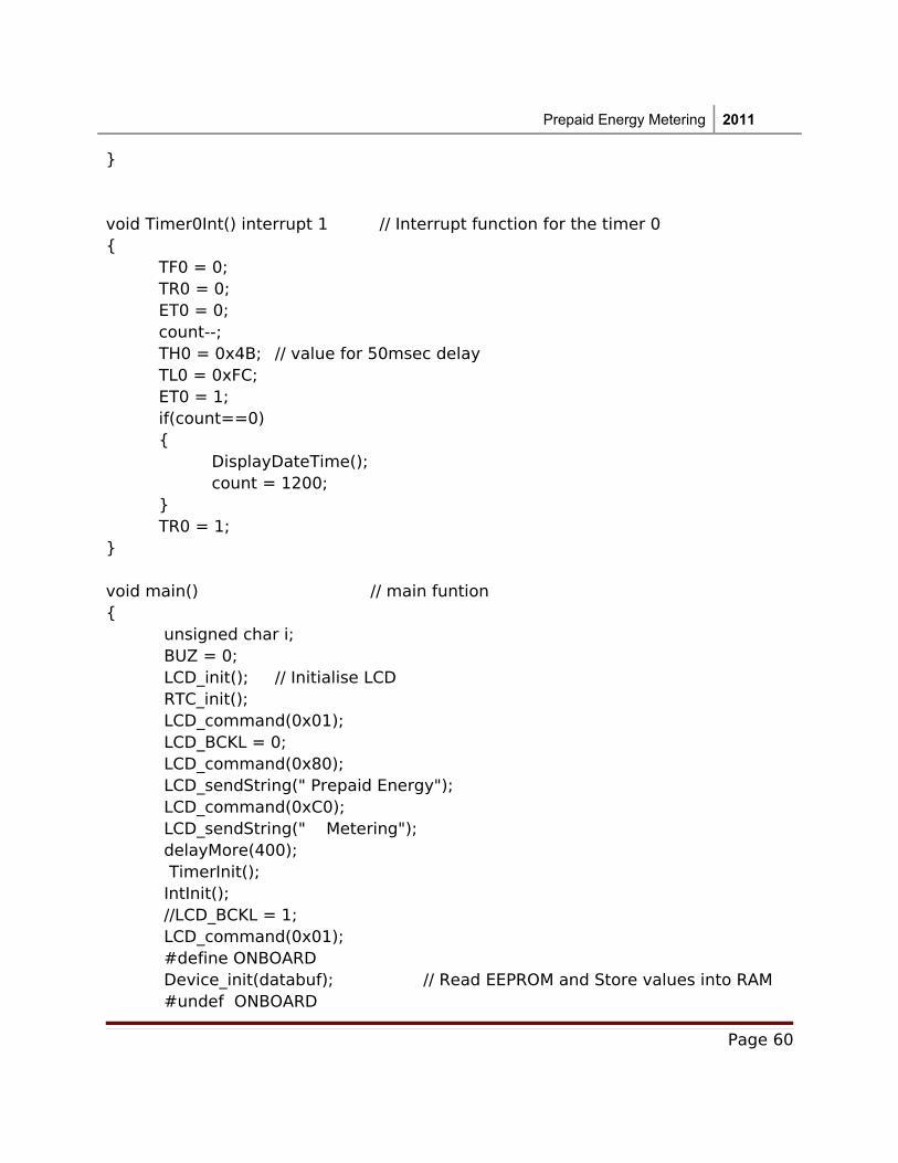
7.2 Firmware code // main.c
#include"main.h" unsigned int count; unsigned int databuf[4]; unsigned int pulseCount,unitConsume,balAmount,tariff,balUnit,totalConsume ; bit RelyOn = 0; bit alarm = 0 ; // Interrupt function for the Pulse sensingvoid pulseISR() interrupt 0
//unsigned int i;EX0 = 0;if(RelyOn) // If rely is ON
if(balAmount >= tariff)pulseCount++; // Count LED Pulses
if(pulseCount >= ONE_UNIT) // Reaches One Unit Of Electricity
pulseCount = 0;unitConsume++; // count usage of each unitLEDRED = 0;delayMore(5);LEDRED = 1;//totalConsume++;if(balAmount >= tariff)
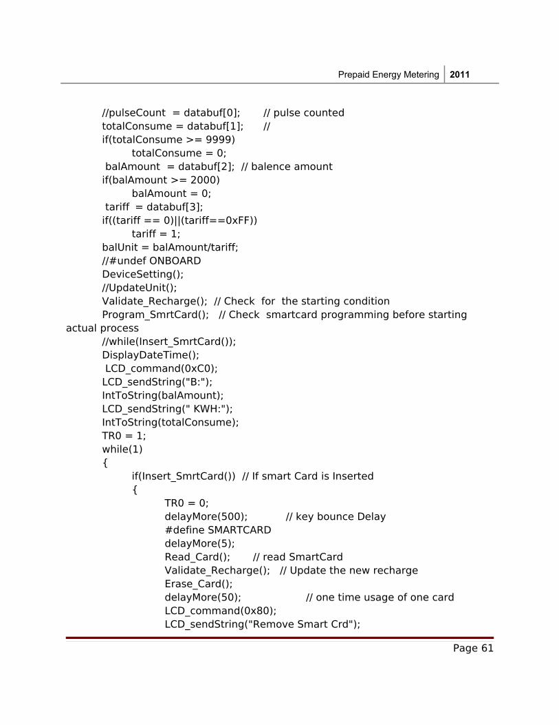
DisplayDateTime(); LCD_command(0xC0); LCD_sendString("B:"); IntToString(balAmount); LCD_sendString(" KWH:"); IntToString(totalConsume); TR0 = 1; while(1) if(Insert_SmrtCard()) // If smart Card is Inserted
TR0 = 0;delayMore(500); // key bounce Delay#define SMARTCARDdelayMore(5);Read_Card(); // read SmartCardValidate_Recharge(); // Update the new rechargeErase_Card();delayMore(50); // one time usage of one card LCD_command(0x80);LCD_sendString("Remove Smart Crd");