Page 1
PREPARATION OF SILICA NANOPARTICLES
USING MICROEMULSION TECHNIQUES
A THESIS SUBMITTED IN PARTIAL FULFILLMENT
OF THE REQUIREMENTS FOR THE DEGREE OF
Bachelor of Technology
In
Chemical Engineering
By
V GANESH ADITYA BIKASH RANJAN MALLICK (10400004) (10400014)
Under the Guidance of
Dr. SANTANU PARIA
Department of Chemical Engineering
National Institute of Technology
Rourkela 2008
Page 2
National Institute of Technology
Rourkela
CERTIFICATE
This is to certify that the thesis entitled, “PREPARATION OF SILICA NANOPARTICLES USING MICROEMULSION TECHNIQUES”
Submitted by Mr. Bikash Ranjan Mallick & Mr. V Ganesh Aditya
In partial fulfillments for the requirements for the award of Bachelor of Technology Degree in Chemical Engineering
At National Institute of Technology, Rourkela is An authentic work carried out by him under my supervision and guidance.
To the best of my knowledge, the matter embodied in the thesis has not been submitted to
any other University / Institute for the award of any Degree or Diploma.
Date: Prof. Santanu Paria Dept. of Chemical Engineering
National Institute of Technology Rourkela
Page 3
ACKNOWLEDGEMENT
I would like to make my deepest appreciation and gratitude to Prof. Santanu Paria for
His invaluable guidance, constructive criticism and encouragement during the course
of this project.
We would like to thank Prof. R. K. Singh for being a uniformly excellent advisor. He was
always open minded, helpful and provided us with a strong broad idea.
I would like to express my gratitude to Shri Rakesh Pattnaik for helping us in
characterizing the samples under the SEM.
Grateful acknowledgement is made to all the staff and faculty members of Chemical
Engineering Department, National Institute of Technology, Rourkela for their consistent
encouragement.
I would also like to extend my sincere thanks to all my fellow students (UG, PG and
Research) for their time, invaluable suggestions and help. In spite of the numerous citations
above, the author accepts full responsibility for the contents that follow.
9.5.2008 Bikash Ranjan Mallick (10400014) V Ganesh Aditya (10400004)
Page 4
CONTENTS
Abstract i
List of Figures ii
List of Tables iv
References v
Chapter 1 GENERAL INTRODUCTION 1
1.1 Nanoparticles 3
1.2 Micoemulsion 4
1.3 Methods of preparation 5
1.4 Organization of project 6
Chapter 2 LITERATURE REVIEW 7
2.1 Template Method 9
2.1.1 Preparation of hollow nanoparticle as a template under sonication
10
2.1.2 Preparation of hollow nanoparticle through a self-templating solid gas interface reaction
12
2.1.3 Preparation of monodispersed hollow sphere 13
2.2 Hydrothermal Method 16
2.3 Solvothermal Method 18
2.4 Emulsion Method 19
2.4.1 Emulsion–solvent evaporation method to prepare microporous polymeric hemi – cells
20
Page 5
2.4.2 Preparation of hollow microcapsule by immobilization method
21
2.4.3 Preparation of heterogeneous composite particle with hollow structure
23
2.4.4 Preparation of core– shell silica particle through microemulsion method
25
2.5 Objective of the Project 28
Chapter 3 EXPERIMENTAL WORK 29
3.1 Material 30
3.2 Procedure 30
3.3 Characterization 31
Chapter 4 RESULTS AND DISCUSSION 32
4.1 Effect of pH value of aqueous phase 36
4.2 Role of butylamine/ammonia as base catalyst 37
4.3 Effect of R value 38
Chapter 5 Conclusion 40
Page 6
i
ABSTRACT
Silica nanoparticles have been prepared in this work using water in oil (W/O)
emulsion system at room temperature that employs a water-soluble amine as catalyst
and tetraethylorthosilicate (TEOS) as the silica source. The pH value of the aqueous
phase and the water: surfactant ratio were found to be the key factors contributing to
the formation and final size of stable and regular spherical silica particles. When the
pH value of the aqueous phase was controlled between 8 and 9, silica particles could
be synthesized. The shell thickness of the hollow particles as and when prepared was
found to increase with the length of the hydrocarbon tail of the amine catalyst. The
viscosity of the external oil phase determined the shape regularity of the spherical
silica hollow particles. The kinetics of the formation of silica hollow particles was
believed to be based on the difference between the hydrolysis rate and the
condensation rate of TEOS, which can be adjusted by the pH value of the aqueous
phase. After treating the core-shell particles with concentric nitric acid, the hollow
silica spheres were obtained correspondingly. The particles were characterized by
Scanning electron Microscope (SEM), Optical Microscope and UV
Spectrophotometer. The study shows that through further processing, advanced
materials could be prepared; and that the hollow silica spheres could be potentially
used as a novel class of catalyst supports.
Keywords: Scanning electron microscopy(SEM); Colloids; Nanoparticles; Silica; Silicates; R
Ratio; Solution chemistry;
Page 7
ii
LIST OF FIGURES
Figure
No
TITLE Page
No.
1.1 Chart representing sizes of different materials 3
1.2 Phase diagram for CTAB/1-hexanol/water systems 4
2.1.1 TEM images of CuS samples prepared under different
conditions
11
2.1.2 Possible Mechanism for formation of hollow spherical
assemblies
11
2.1.3 A schematic illustration of the formation process of
nanosized AlN hollow spheres
13
2.1.4 Fabrication Procedure of hollow Spheres 14
2.1.5 TEM images of the composite spheres 15
2.2.1 SEM images of ZnO samples prepared with same
experimental condition (initial pH 9 and final pH 10)
at 100 C: (a) ZnO under conventional stirring, and (b,
c) hydrothermal treatment in autoclave
16
2.2.2 SEM and TEM images of the sample prepared with pH
8 and 10
17
2.3.1 Representation for possible growth mechanism for
KNiF3
19
2.4.1 Optical photomicrographs of the hemi-shell
morphological development with various time intervals
and SEM micrograph of the final morphology
20
2.4.2 Schematic representation of Hemi Shell formation 21
2.4.3 Schematic illustration of forming hollow microcapsule
with NiCl2 dotted in the interior surface
22
Page 8
iii
2.4.4 Polyurea Microcapsules with encapsulated NiCl2 22
2.4.5 TEM images of hollow silica spheres functionalized
with MPTMS at different time intervals
23
2.4.6 Schematic Representation of Nanoparticle formation 27
3.1.1 Stepwise procedure for formation of silica
nanoparticles
31
4.1 SEM images of a highly concentrated bunch of Si
nanoparticles
35
4.2 SEM characterized nanoparticles synthesized at a pH
value controlled around 11.6
37
4.3 SEM images at pH value controlled around 11 37
4.4 The SEM images of the hollow silica particles
characterized at pH 10 and R = 8-9
38
4.1.1 Schematic illustration of silica hollow particles’
formation in W/O emulsion
38
4.1.2 Effect of pH on particle size (a)pH=9-10 (b)pH>11 39
4.3.1 Effect of R on particle size (a) R=10 (b) R=20 41
Page 9
iv
LIST OF TABLES
Table No Title Page No
3.1 pH Values 31
4.1 Material values at a constant R = 10 34
4.2 Material values at a constant pH = 11.6 34
Page 10
1
Chapter 1
GENERAL INTRODUCTION
Page 11
2
Nanotechnology has emerged as a promising vehicle for an emerging scientific and
technological revolution. Richard Feynman, in his seminal 1959 lecture, proposed a
variety of potential nanomachines, which could be engineered to a higher level of
functional efficiency than currently available manufactured devices by exploiting
changes in the behavior of matter at the nanometer length scale. In order to realize this
goal, scientists and engineers have to devise strategies to synthesize specified
functional nanoparticles, and then learn how to incorporate them into devices in which
they might function individually or in cooperation with other nanoparticles or devices.
This “bottom up” approach of “nanoparticle design” followed by “device assembly
from nanoparticles” is widely accepted as a promising route to nanotechnological
applications, separate from a more traditional “top down” approach followed in
semiconductor and electronics research. In recent years, “bottom up” nanotechnology
has led to promising innovations in fields such as biotechnology, electronics and
catalysis. This approach also could potentially address the ever-present need to
miniaturize components, especially in the electronics industry.
Today it is widely accepted that reduction in size to a molecular level (nanometer
scale) cannot be achieved with conventional “top down” methods (e.g.
photolithography, etching etc). Thus, nanoparticle-based (or “single-molecule” based)
device development is emerging as a fundamental requirement in realizing the goals
of nanotechnology. Single-molecule devices can be faster, more precise, and more
efficient in energy utilization than devices made of bulk materials. Numerous
molecules having electronic properties have hence been identified and reported [1].
Single molecule logic gates and circuits have been theorized and detailed molecular
designs have been put forward for actualization and incorporation in solid state
electronics. Biotechnology is also stressing the need for nanoscale devices for a
variety of applications, notably in DNA sequencing and biosensing.
The nanometer scale of these structural features offers unique engineering challenges.
First, there is little quantitative understanding of the processes governing the
controlled synthesis of important synthetic nanoscale materials like nanotubes,
nanowires and nanodots which could be used as components of such devices.
However, knowledge of these processes is essential for rational design of
nanodevices, since fine control over dimensions, structure, and composition is key to
Page 12
3
producing nanomaterials suitable for incorporation in devices. Additionally, the
properties of any nanoscale system are controlled by “molecular” physics and
confinement effects as opposed to “bulk” physics, and it is well known that the
functional properties of nanomaterials are usually very different from the
corresponding bulk materials. Once the synthesis-structure-size-shape-property
relations of a nanoparticle are accurately determined, one can begin to rationally
address the next set of problems such as manipulation of the nanoparticle and
direction to a specific location in a device, and connection of the device to a larger
system or collection of devices.
1.1 NANOPARTICLES
Nanoparticles can be defined as materials and systems whose structures and
components exhibit novel and significantly improved physical, chemical and
biological properties, phenomena and processes due to their nanoscale size i.e. in a
range of 1-100nm. Nanotechnologies have become one of the promising research
areas which might bring a significant progress into material and device development.
At present, there is a wide spectrum of technological approaches capable of producing
nanoparticles and simple nanostructures, however, none of them can be considered as
an ideal and generally acceptable tool.
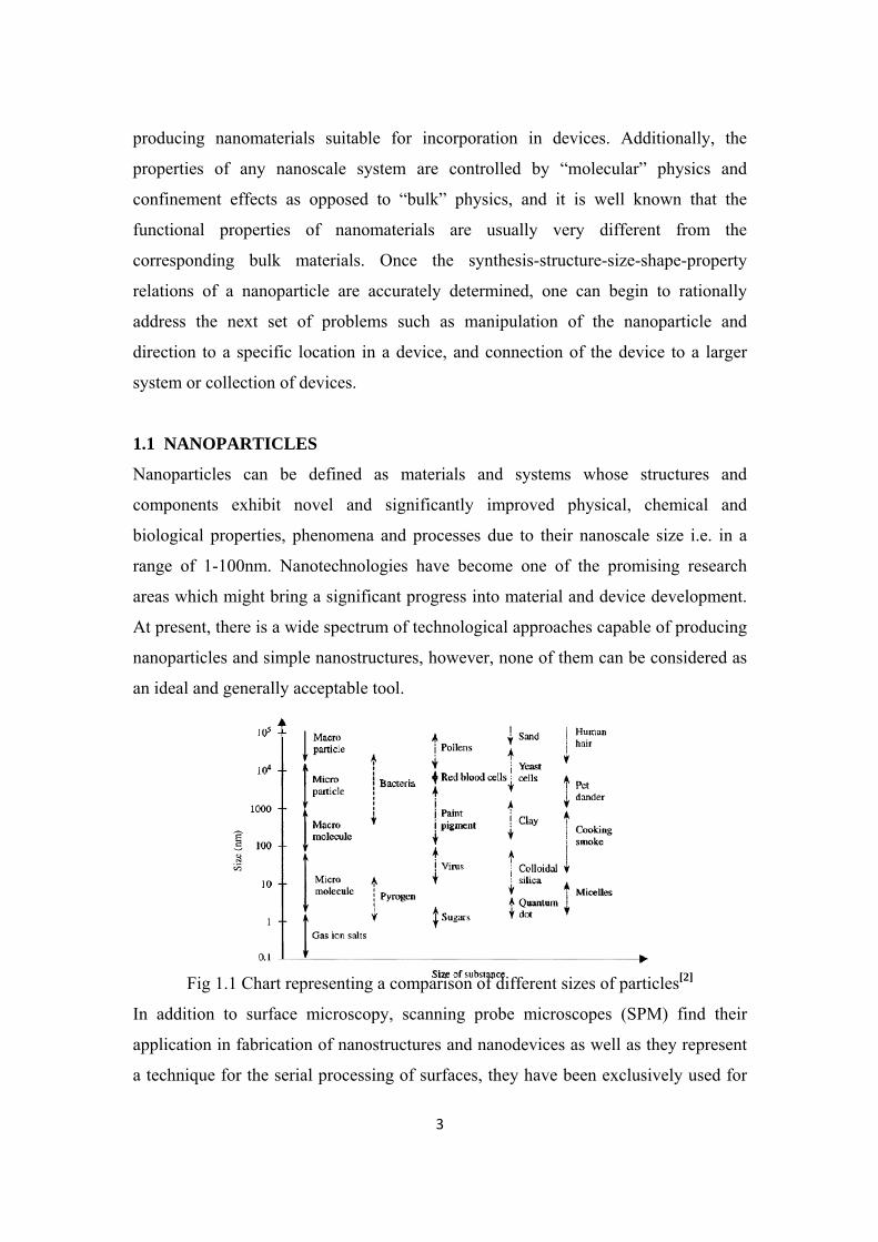
Fig 1.1 Chart representing a comparison of different sizes of particles[2]
In addition to surface microscopy, scanning probe microscopes (SPM) find their
application in fabrication of nanostructures and nanodevices as well as they represent
a technique for the serial processing of surfaces, they have been exclusively used for
Page 13
4
applications in laboratory-scale experiments on building the nanostructures and
verification of their fundamental properties.
1.2 MICROEMULSIONS
A microemulsion is a thermodynamically stable dispersion of two immiscible fluids;
the system is stabilized by added surfactant Different types of microemulsion are
known, such as water-in-oil (w/o), oil-in-water (o/w), water-in-sc-CO2 (w/sc- CO2). A
“water-in oil” microemulsion is formed when water is dispersed in a hydrocarbon
based continuous phase, and is normally located towards the oil apex of a
water/oil/surfactant triangular phase diagram
Fig 1.2 Phase diagram for CTAB/1-hexanol/water systems[3]
In this region, thermodynamically driven surfactant self-assembly generates
aggregates known as reverse or inverted micelles (L2 phase on Fig. 1) spherical
reverse micelles, which minimize surface energy are the most common form. Added
polar or ionic components will become compartmentalized into the central cores of
these reversed micelles, hence affording fine dispersion of inorganic materials in oil.
It is important to recognise that these systems are dynamic — micelles frequently
collide via random Brownian motion and coalesce to form dimers, which may
exchange contents then break apart again [4,5]. Clearly, any inorganic reagents
encapsulated inside the micelles will become mixed. This exchange process is
fundamental to nanoparticle synthesis inside reversed micellar ‘templates', allowing
different reactants solubilized in separate micellar solutions to react upon mixing.
Micelles in these systems can be described as “nanoreactors”, providing a suitable
environment for controlled nucleation and growth. In addition, at the latter stages of
Page 14
5
growth, steric stabilisation provided by the surfactant layer prevents the nanoparticles
from aggregating.
1.3 METHODS OF PREPARATION
Generally, nanostructures with hollow interior are commonly prepared by coating the
surfaces of colloidal particles (e.g., silica bead, silver or gold colloids, and polymer
latexes) with thin layers of the desired materials (or its precursor), followed by
selective removal of the colloidal templates through wet chemical etching or
calcinations. It was reported that some inorganic hollow spheres had been prepared
by different methods, involving the synthesis of intact inorganic shells around
sacrificial templates and in situ templates. The main disadvantage using pyrolysis is
that costly equipment is required. In addition, precipitation method has been
successfully employed. However, this method was affected by many factors, such as
precipitation agent, pH, and temperature and solution concentration; hence the process
is difficult to control.
Most of the work involving nanoparticle preparation using microemulsions has
focused on forming nanoparticles through a reaction carried out by mixing two
identical microemulsions each containing one of the reactants forming the
nanoparticle. For rapid reactions, the mixing of two microemulsions technique is
limited by the solubilizate exchange dynamics. Slow solubilizate exchange dynamics
contributes to simultaneous nucleation and aggregation, which in turn results in large
particles with wide size distribution. Intermicellar exchange of solubilizate is achieved
through a Brownian motion of the reverse micelles, surfactant layer opening upon
coalescence, diffusion of the solubilizate molecules, and finally decalescence to
reverse micelles. In one approach of forming nanoparticles aimed at minimizing the
role of the surfactant surface layer opening by means of a direct reaction with the
surfactant counter ion in a single microemulsion. Another involved the direct
formation of nuclei of the nanoparticles while accommodating the aqueous solution of
the added reactant into the water pools of the reverse micelles due to the presence of
the counter ion in each reverse micelle.
Page 15
6
1.4 ORGANIZATION OF PROJECT REPORT
Preliminary introduction about nanoparticles, hollow silica spheres, types and
properties of micro-emulsion, various methods of preparation and organization of
project report is discussed in chapter 1. Chapter 2 provides a detailed discussion of
literature on the mechanism & techniques of reaction, effects of important parameters
on the final results. The main objective of the present work, which is based on the
literature survey on preparation of silica nanoparticles, is presented towards the end of
chapter 2. In chapter 3, the various techniques used in the present work such as
materials used, preparation of micro-emulsion, preparation of nanoparticles are
described in detail. Chapter 4 describes the results and characterization of the particles
formed in the solution. Finally, conclusions of project work are given in Chapter 5.
Page 16
7
Chapter 2
LITERATURE REVIEW
Page 17
8
There are many methods proposed by many works to prepare hollow nanoparticles.
Among them most popular, significant, and cost effective methods are core – shell
templating method, solvothermal method, sol – gel method, self assembly, and last but
not least is microemulsion method.
Many technologies have been explored to fabricate nanostructures and nanomaterials.
These technical approaches can be grouped in several ways. One way is to group them
According to the growth media:[6]
1. Vapor phase growth, including laser reaction pyrolysis for nanoparticle
synthesis and atomic layer deposition (ALD) for thin film deposition.
2. Liquid phase growth, including colloidal processing for the formation of
nanoparticle and self assembly of monolayers.
3. Solid phase formation, including phase segregation to make metallic particles
in glass matrix and two-photon induced polymerization for the fabrication of
three dimensional photonic crystal.
4. Hybrid growth, including vapor-liquid-solid (VLS) growth of nanowires.
Another way is to group the techniques according to the form of products:
1. Nanoparticles by means of colloidal processing, flame combustion and phase
segregation.
2. Nanorods or nanowires by template-based electroplating, solution-liquid-solid
growth (SLS) and spontaneous anisotropic growth.
3. Thin films by molecular beam epitaxy (MBE) and atomic layer deposition.
4. Nanostructured bulk materials, for example, photonic band gap crystals by self
assembly of nanosized particles.
In most of the preparation methods, it’s very difficult to control size and shape of the
particle except microemulsion method, in which we need to control one thing and
that, will control everything for particle synthesis.
Page 18
9
2.1 TEMPLATE METHOD
In the template formation technique the basic formation principle involves the
template cores to be sacrificed by either dissolution or calcination at high temperature
in order to achieve hollow spheres, while the osmotic pressure will usually deteriorate
the shell integrity resulting in perforation or fracture. Alternatively, soft template
cores for example emulsion droplets, gas bubbles, quasireverse emulsions, are used to
synthesize hollow spheres.
The cores can be easily removed by evaporating liquids at elevated temperature.
However, composition of the coating materials is rather restricted, and the weak liquid
cores are easily deformed and coalesced during synthesis. To avoid using core
templates, hollow spheres such as polyelectrolyte capsules, viral capsids, vesicles
have been recently used as templates to synthesize composite hollow spheres. During
the template synthesis using viral capsids, materials usually grow in the cavity rather
than within the shell. It is not easy to form composite shells. The hollow spheres such
as polyelectrolyte capsules, viral capsids, vesicles have been recently used as
templates to synthesize composite hollow spheres. During the template synthesis
using viral capsids, materials usually grow in the cavity rather than within the shell.
Polymeric gels are such interesting materials with tunable chemistry and physical
environment, which can be used as templates to induce favorable growth of materials
with varied composition through specific interactions. When LBL assisted
polyelectrolyte gel hollow spheres are used to prepare composite hollow spheres,
ionic cross-linking nature within the shell significantly sacrifices the functional groups
such as proton ions.
In this method, first of all, a core is prepared by using inorganic or organic material.
Then using Si or Ag a shell is formed around the core by layer by layer deposition or
by using something other procedure. Then core part is removed by treating core –
shell particle with acid at suitable concentration or by calcinating the core – shell
particle, which produce a hollow shell particle. The main disadvantages in this case,
are, we have to choose an appropriate cell particle, on which shell can be formed, and
which could be easily removed after formation of the particle. Secondly, we have to
maintain most suitable acid or other solvent to dissolve cell.
Page 19
10
Given below are some examples of template method:
2.1.1 PREPARATION OF HOLLOW NANOPARTICLES AS A TEMPLATE
UNDER SONICATION
Cyclodextrins (CDs), torus-shaped cyclic oligosaccharides consisting of six or more 1,
4-linked D-glucopyrannose units, are usually used to fabricate some new structured
materials. Some modified CDs could form nanospheres by the aggregation among the
interaction of molecules. 2-Hydroxypropyl- β-cyclodextrin (2-HP-β-CD) is one kind
of derivatives of CDs and has been widely applied to design new pharmic carrier
system because of its very good solubility in water [7]. Now is used their complex
structure and valence state results in to from various stoichiometries. CuS shows
metallic conductivity and transforms at 1.6 K into a superconductor. The photoelectric
properties of the copper sulfide can be used as the quantum dots in photoelectron
transformation devices.
Sonication is act of applying energy to agitate particles in a simple, for various
purposes. It can used to speed dissolution, by breaking intermolecular bonds. It’s
specially useful when its not possible to stir samples [7].High-intensity ultrasound is
induce for the fabrication of copper sulfide hollow nanospheres in water solution
containing Cu(CH3- COO)2, thiourea and 2-HP-β-CD. At the end of the reaction, a
great amount of black precipitates occurred. The sonication was conducted without
cooling so that a temperature of about 330 K was reached at the end of the reaction.
After cooling to room temperature, the precipitates were centrifuged, washed with
distilled water and dried in air at room temperature.
Without 2-HP-β-CD, the prepared products were aggregation composed of CuS
nanoparticles. With 2-HP-β-CD adding into the solution, the products were semi-
hollow spherical structures. When 2-HP-β-CD was added into the solution, the
product changed to be uniform CuS hollow spheres with average size of 30 nm. Thus
with increase in quantity the size of the sphere also increases.
Page 20
11
Fig 2.1.1 TEM images of CuS samples prepared under different conditions: (a)
without 2-HP-b-CD (b) 2 g 2-HP-b-CD (c) 4 g 2-HP-b-CD (d) 8 g 2-HP-b-CD[8]
The Cu ions would be absorbed by the 2-HP-β-CD to form the Cu–HP-b-CD
complex. When the mixture solution is exposed under ultrasound, the 2-HP-β-CD
molecules would cross-link with each other through the hydroxyls and
hydroxypropyls. Due to the special structure of the 2-HP-β-CD, the cross-link of the
particles inclined to form the sphere-like structure. Therefore the higher concentration
of 2-HP-β-CD led to bigger spheres. In the initial stage, the Cu ions would be
absorbed on 2-HP-β-CD molecules to form a homogenous complex spheres. As
shown in the Figure 2.1.2, the cup-like part of the 2-HP-β-CD model would appear on
the surface of the spheres.
Fig 2.1.2 the possible mechanism for formation of hollow spherical assemblies[8].
Hence parts of the Cu ions would be exposed on the surface of the spheres equably.
In the presence of sonication, the S ions could be released slowly into the solution and
first reacted with the Cu ions on the surface of the complex spheres giving rise to the
Page 21
12
CuS nuclei. Due to the strong adsorption ability of 2-HP-β-CD, the nuclei could also
be adsorbed on their surface. With time increasing, the nuclei would grow up until the
particles become stable. At the end of reaction, the process led to hollow spherical
structure with one-layer shell.
2.1.2 PREPARATION OF HOLLOW NANOPARTICLE THROUGH A SELF-
TEMPLATING SOLID GAS INTERFACE REACTION
In this method same material is being used for both reactant and templates for hollow
nanosphere formation. Aluminum nanoparticles were synthesized by hydrogen plasma
metal reaction. An aluminum ingot was melted and evaporated by arc in a 1:1 mixture
of argon and hydrogen[9]. The evaporated Al condensed into nanoparticles when
leaving the hot plasma area and were transported into a filter for collection by
circulate pumping. The Al nanoparticles were passivated with a mixture of argon and
air to prevent the particles from burning before removing from the collector. The
synthesis of nanosized AlN hollow spheres was carried out in a horizontal quartz tube
furnace. Al nanoparticles were loaded in a ceramic boat which was placed in the
center of the tube furnace. The system was first evacuated to 0.6 Pa and then flushed
with 99.99% Ar three times to remove oxygen and moisture. The system was then
filled with Ar to 1 atm and was heated to 1000°C at 20 C/min under a constant Ar
flow of 100 standard cubic centimeters per second (sccm). When the furnace
temperature reached 1000°C, the gas flow was switched to a mixture of 25 sccm Ar
and 25 sccm NH3 (99.99%). The system was maintained in that condition for 3 h
before it was allowed to cool down to room temperature in a pure argon flow. The
powder in the ceramic boat turned from black to gray. Thus hollow nano particle is
prepared.
When the AlN layer is formed at the surface of each Al nanoparticle through the
interface reaction, the Al and N atom have to pass through the AlN layer by solid-state
diffusion to meet each other to form AlN. Aluminum was established to be the
dominant diffusion species in the Al–N diffusion couple. Therefore, there will be a net
outward matter flux and an inward vacancy flux for compensation due to the outward
diffusion rate of Al is much faster than the inward diffusion rate of N. The vacancies
Page 22
13
accumulate at the center of the nanoparticle, leading to the void formation. The
vacancy involved diffusion mechanism is known as the Kirkendall effect which was
first proposed by Kirkendall [10] .This effect has been known to cause void formation
for a long time. Kirkendall effect usually involves the self-templating effect of one
precursor. No additional template agents are needed, which makes this approach an
economic way to obtain hollow structures.
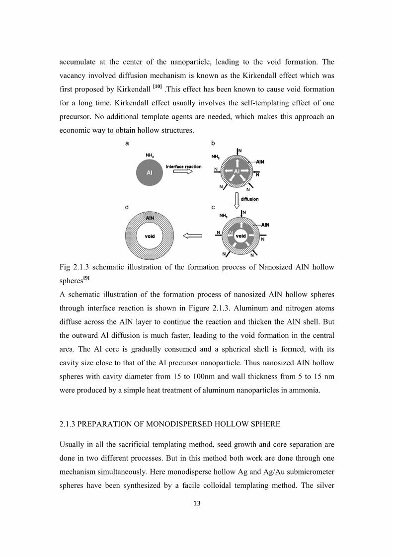
Fig 2.1.3 schematic illustration of the formation process of Nanosized AlN hollow
spheres[9]
A schematic illustration of the formation process of nanosized AlN hollow spheres
through interface reaction is shown in Figure 2.1.3. Aluminum and nitrogen atoms
diffuse across the AlN layer to continue the reaction and thicken the AlN shell. But
the outward Al diffusion is much faster, leading to the void formation in the central
area. The Al core is gradually consumed and a spherical shell is formed, with its
cavity size close to that of the Al precursor nanoparticle. Thus nanosized AlN hollow
spheres with cavity diameter from 15 to 100nm and wall thickness from 5 to 15 nm
were produced by a simple heat treatment of aluminum nanoparticles in ammonia.
2.1.3 PREPARATION OF MONODISPERSED HOLLOW SPHERE
Usually in all the sacrificial templating method, seed growth and core separation are
done in two different processes. But in this method both work are done through one
mechanism simultaneously. Here monodisperse hollow Ag and Ag/Au submicrometer
spheres have been synthesized by a facile colloidal templating method. The silver
Page 23
14
nanoparticle seeds are synthesized on the silica colloids surface through the
electroless plating approach to avoid the complex surface functionalization, and the
subsequent seeding growth and dissolving silica core are carried out simultaneously.
The prepared hollow spheres remain mostly the fine monodispersity and spheric shape
of the silica core, and can self-assemble directly into ordered structure.
Fig 2.1.4 Fabrication procedure of hollow spheres[10] Fig 2.1.4 shows the preparation procedure of the monodisperse hollow Ag and Ag/Au
spheres[10]. First of all, silica colloids were dispersed in ethanol containing
PVP(polyvinylpyrrolidone), then [Ag(NH3)2]+ (0.1 M) ions solution was added
quickly under stirring at room temperature, and the complex [Ag(NH3)2]+ ions were
absorbed by the negatively charged Si–OH groups on the surface of the silica colloids.
Then, the colloids were washed with ethanol by centrifugation and ultrasonic
dispersion to remove the excessive [Ag(NH3)2]+ ions, and dispersed in ethanol. Then,
KBH4 solution was added quickly to reduce the [Ag(NH3)2]+ ions, and the surface of
the colloids was covered uniformly with silver nanoparticles. Then, after sometime
the colloids were washed with distilled water to remove the excessive KBH4. Silica
colloids after seeding were added into aqueous ethanol in which the ethanol–water
volume ratio is 1:1. Then, 10% HCHO diluted with distilled water was added
dropwise to grow the silver nanoparticles. During the seeding growth procedure, with
increasing the shell thickness, the silica core is dissolved gradually:
SiO2 + 2OH- → SiO32- + H2O
Page 24
15
The shell made of silver nanoparticles on the surface of the silica colloids after surface
seeding is incomplete, both OH- and SiO32- can diffuse across this shell until the silica
core has been completely consumed. Controlling the amount HCHO, monodisperse
hollow Ag spheres with controllable shell thickness can be obtained.
Fig 2.1.5 TEM images of the composite spheres: a) silica colloids after seeding b) to
d)silica colloids after seeding and seeding growth, the shell thickness and the
corrosion degree of the silica core increase from b to d[10].
Fig 2.1.5 shows the typical TEM images of the composite spheres at different stages
of the fabrication process of hollow silver spheres. In this case, the complex
[Ag(NH3)2]+ rather than silver ions as the precursor of the silver nanoparticles
because the reduction of the former is more controllable and uniform, PVP is
exploited to protect the silica colloids from aggregation due to the charge
neutralization during the absorption process of the complex [Ag(NH3)2]+, and the
‘‘rapid’’ reducing agents-KBH4 is used to assure the seeds size is very small. By
controlling the seeding growth speed and the dissolving speed of the silica core, the
spheric shape and mono-dispersity of the silica colloids are preserved mostly
throughout the seeding growth process.
During seeding growth process, the role of C6H5O7Na3.2H2O is to slow down the
reduction speed through the coordination between citrate and silver ions and work as
stabilizer to protect the colloids from aggregation; NaOH is used to dissolve gradually
Page 25
16
the silica core; 10% HCHO solution is added dropwise to control the reaction speed
and the reduction amount of silver ions, and increase the silver shell thickness. The
initial concentration of NaOH in the seeding growth solution is crucial for the
formation of hollow silver spheres. So by using this method, its possible to prepare
hollow nanaoparticle, by simultaneous seed formation and core breaking without
using any foreign surfactant.
2.2 HYDROTHERMAL METHOD
For preparing nanoparticle with hollow structure different materials are used. Among
them ZnO is an important one, because it can be used in photelectrode, solar cells, and
nanolasers, because of its wide band gap and large excitation binding energy of 60
meV. Different nanostructures including nanowires, nanorods, nanotubes,
nanoribbons, nanoneedles, nanocables, tetrapods, comb-like structures can be
prepared from ZnO and these new structures have a wide application in different
areas. Here in this case hydrothermal method is used for preparation of ZnO
nanoparticles in which temperature and pH has significant role.
Fig 2.2.1 SEM images of ZnO samples prepared with same experimental condition
(initial pH 9 and final pH 10) at 100 C: (a) ZnO under conventional stirring, and (b,
c) hydrothermal treatment in autoclave[11]
For synthesis of ZnO nanostructures, zinc acetate was slowly added to an aqueous
solution of triethanolamine to reach the desirable pH referred to as the initial pH.
Page 26
17
Then, potassium hydroxide was added to the solution pH to a certain value referred to
as the final pH. The resultant solution was heated at certain temperature (100°c), from
which ZnO hollow particles are prepared.
Fig. 2.2.2 (a) SEM and (b, c) TEM images of the sample prepared with pH 8 and
similarly (d) SEM and (e) TEM images of the sample prepared with pH 9.[11]
As seen in Figure 2.2.1, conventional stirring results in the formation of highly
agglomerated nanoparticles, while uniform nanospheres are formed during
hydrothermal synthesis. Since the formation of ZnO nanostructures is due to the
decomposition of amine-based zinc complex in basic media, the solution pH during
the formation and decomposition of the zinc complex has an important influence on
the morphology of ZnO nanostructures. For typical zinc complex formed at pH 8,
decomposition at pH 10 results in the formation of ZnO nanoparticles consisted of
tinier nanocrystals (Fig. 2.2.2a–c). Since the decomposition pH controls the rate of
ZnO formation it just affects the size but not the shape of nanostructures. For higher
pH (as the difference between the initial and final PHS is higher), just the nucleation
rate increases to avoid continuous growth of the particles to achieve larger sizes.
Whereas the initial pH affects the nature of the zinc complex generated, and
generation of zinc complex at pH 9 leads to the formation of hollow nanospheres (Fig.
2.2.2 d and e).
Page 27
18
2.3 SOLVOTHERMAL METHOD
Many methods can effectively fabricate hollow spheres, for instance, liquid droplets.
Colloidal templating, coordination polymer, and self-assembly processes. Generally,
these methods require additional template materials or surfactants. To simplify
preparation procedure, solvothemal method is very simple. In this method, a solution
is prepared by using required reactants, and then the product is heated and dried to get
hollow particles.
For example to synthesize potassium nickel fluoride (KNiF3) hollow NiCl2·6H2O was
dissolved in ethanol[13], then KF aqueous solution was added in, the solution turned
turbid immediately after adding KF, indicating sediment formation. The mixture was
filled in a Teflon-lined autoclave and was maintained at 110C and then cooled to
room temperature naturally. The product was filtered and washed with absolute
ethanol and distilled water several times, until pistachio precipitate is collected.
Finally product was dried in a vacuum box.
In the present synthetic process, the composition and morphology of the product are
greatly affected by the proportion of reactants. The reaction process may be
formulated as follows: in ethanol solution, K+ ions and Cl− ions firstly form KCl
spherical precipitate
K+ + Cl− → KCl, (1)
Where the KCl formed absorbs the F− ions and Ni2+ ions on its surface. Then, these
ions react with KCl to form KNiF3 nanoparticles under ethanol thermal conditions
Ni2+ + 3F− + KCl → KNiF3 + Cl−, (2)
If the molar ratio between initial materials KF and NiCl2 is less than 1, unreacted Cl−
ions (in reaction (1)) block the proceeding of reaction (2). Some Ni2+ ions and F− ions
will form NiF2 precipitate, resulting in the final product is mixture of NiF2 and KNiF3.
However, when the molar ratio between initial materials KF and NiCl2 is relatively
high (e.g., larger than only few hollow spheres, along with a mass of irregular
nanocrystals with different size and dispersivity are obtained. The absence of hollow
spheres in the final product may be due to the fact that large amounts of K+ ions exist
Page 28
19
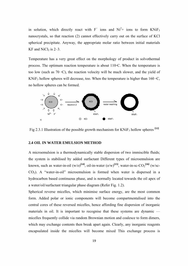
in solution, which directly react with F− ions and Ni2+ ions to form KNiF3
nanocrystals, so that reaction (2) cannot effectively carry out on the surface of KCl
spherical precipitate. Anyway, the appropriate molar ratio between initial materials
KF and NiCl2 is 2–3.
Temperature has a very great effect on the morphology of product in solvothermal
process. The optimum reaction temperature is about 110C. When the temperature is
too low (such as 70 C), the reaction velocity will be much slower, and the yield of
KNiF3 hollow spheres will decrease, too. When the temperature is higher than 160 C,
no hollow spheres can be formed.
Fig 2.3.1 Illustration of the possible growth mechanism for KNiF3 hollow spheres [12]
2.4 OIL IN WATER EMULSION METHOD
A microemulsion is a thermodynamically stable dispersion of two immiscible fluids;
the system is stabilised by added surfactant Different types of microemulsion are
known, such as water-in-oil (w/o)[14], oil-in-water (o/w)[15], water-in-sc-CO2[16] (w/sc-
CO2). A “water-in-oil” microemulsion is formed when water is dispersed in a
hydrocarbon based continuous phase, and is normally located towards the oil apex of
a water/oil/surfactant triangular phase diagram (Refer Fig. 1.2).
Spherical reverse micelles, which minimise surface energy, are the most common
form. Added polar or ionic components will become compartmentalised into the
central cores of these reversed micelles, hence affording fine dispersion of inorganic
materials in oil. It is important to recognise that these systems are dynamic —
micelles frequently collide via random Brownian motion and coalesce to form dimers,
which may exchange contents then break apart again. Clearly, any inorganic reagents
encapsulated inside the micelles will become mixed This exchange process is
Page 29
20
fundamental to nanoparticle synthesis inside reversed micellar ‘templates', allowing
different reactants solubilized in separate micellar solutions to react upon mixing.
Micelles in these systems can be described as “nanoreactors”, providing a suitable
environment for controlled nucleation and growth. In addition, at the latter stages of
growth, steric stabilisation provided by the surfactant layer prevents the nanoparticles
from aggregating.
2.4.1 EMULSION–SOLVENT EVAPORATION METHOD TO PREPARE
MICROPOROUS POLYMERIC HEMI – CELLS
There are many methods used to prepare hollow nanoparticles like emulsion-solvent
evaporation systems, phase separation, emulsion polymerization, and spinning disk
atomization. The most widely used route for manufacture still remains the emulsion-
solvent evaporation technique. In this method, by controlling the solvent evaporation
rate, particles can be modified to be into different shapes and sizes. [17]
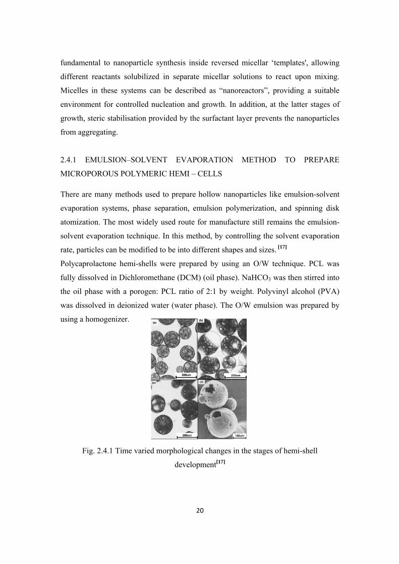
Polycaprolactone hemi-shells were prepared by using an O/W technique. PCL was
fully dissolved in Dichloromethane (DCM) (oil phase). NaHCO3 was then stirred into
the oil phase with a porogen: PCL ratio of 2:1 by weight. Polyvinyl alcohol (PVA)
was dissolved in deionized water (water phase). The O/W emulsion was prepared by
using a homogenizer.
Fig. 2.4.1 Time varied morphological changes in the stages of hemi-shell
development[17]
Page 30
21
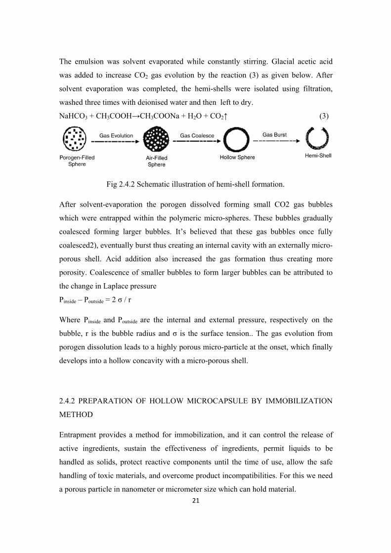
The emulsion was solvent evaporated while constantly stirring. Glacial acetic acid
was added to increase CO2 gas evolution by the reaction (3) as given below. After
solvent evaporation was completed, the hemi-shells were isolated using filtration,
washed three times with deionised water and then left to dry.
NaHCO3 + CH3COOH→CH3COONa + H2O + CO2↑ (3)
Fig 2.4.2 Schematic illustration of hemi-shell formation.
After solvent-evaporation the porogen dissolved forming small CO2 gas bubbles
which were entrapped within the polymeric micro-spheres. These bubbles gradually
coalesced forming larger bubbles. It’s believed that these gas bubbles once fully
coalesced2), eventually burst thus creating an internal cavity with an externally micro-
porous shell. Acid addition also increased the gas formation thus creating more
porosity. Coalescence of smaller bubbles to form larger bubbles can be attributed to
the change in Laplace pressure
Pinside – Poutside = 2 σ / r
Where Pinside and Poutside are the internal and external pressure, respectively on the
bubble, r is the bubble radius and σ is the surface tension.. The gas evolution from
porogen dissolution leads to a highly porous micro-particle at the onset, which finally
develops into a hollow concavity with a micro-porous shell.
2.4.2 PREPARATION OF HOLLOW MICROCAPSULE BY IMMOBILIZATION
METHOD
Entrapment provides a method for immobilization, and it can control the release of
active ingredients, sustain the effectiveness of ingredients, permit liquids to be
handled as solids, protect reactive components until the time of use, allow the safe
handling of toxic materials, and overcome product incompatibilities. For this we need
a porous particle in nanometer or micrometer size which can hold material.
Page 31
22
The success in the synthesis of hollow microcapsule is in controlling the
polymerization speed. The addition of inorganic metal salts, such as NiCl2 lowered the
reaction rate in comparison with that without inorganic metal salts cores, and different
inorganic metal salts presented different reaction rates till the completion of interfacial
polymerization. [18] The urea group could be produced by the reaction between water
and toluene 2,4-diisocyanate (abbreviated as 2,4-TDI) occurring at the oil–water
interface, and unstable –NCOOH2 was prepared and could be easily changed to –NH2
group by the release of CO2.TheresultantTDI-basedwater-borneamin produced urea,
i.e., –NHCONH– by the reaction with another 2,4-TDI. This subsequent reaction
produced a polymer wall membrane onto the emulsion globules. Following this, the
sample was washed and heated, the water inside the microcapsule was vaporized and
thus the formation of hollowmicrocapsule with NiCl2 dotted in the interior surface.
Fig 2.4.3 gives the complete process diagrammatically.
Fig 2.4.3 Schematic illustration of forming hollow microcapsule with NiCl2 dotted in
the interior surface[18]
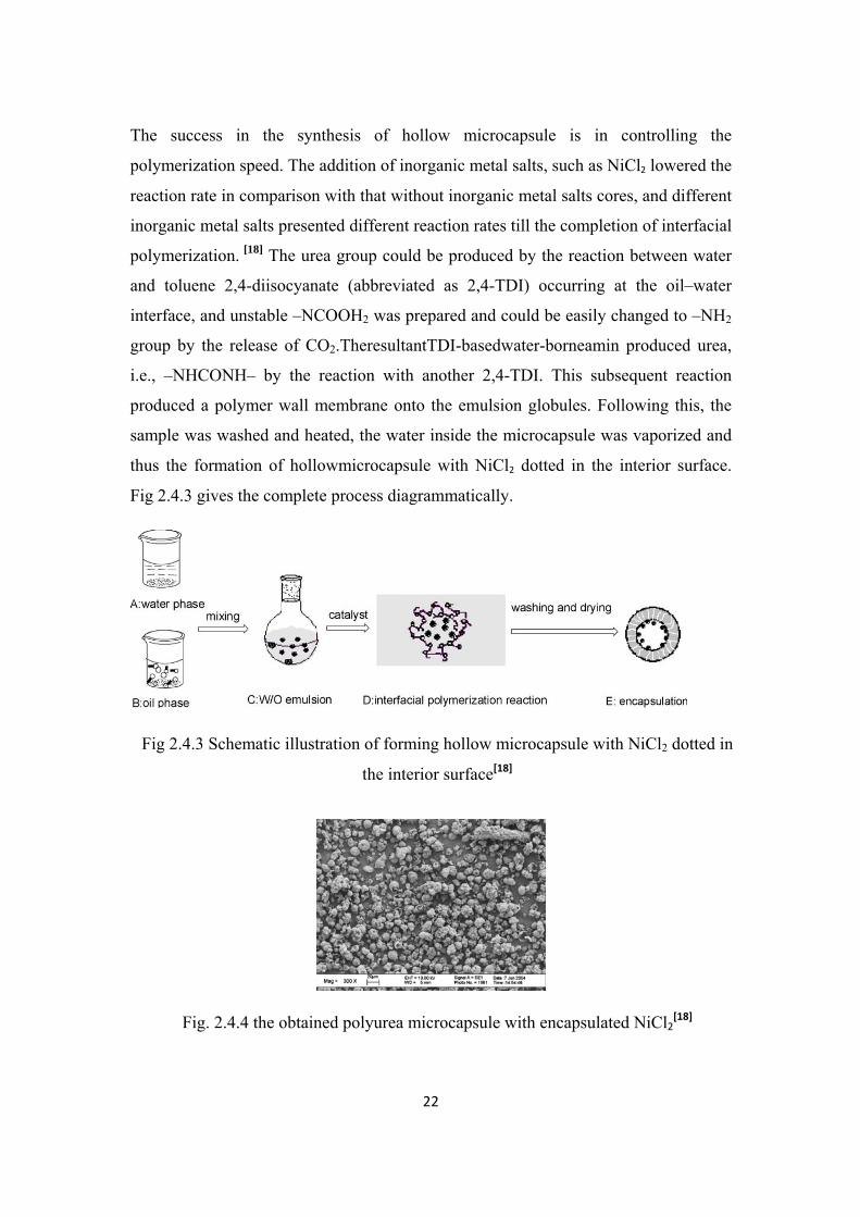
Fig. 2.4.4 the obtained polyurea microcapsule with encapsulated NiCl2[18]
Page 32
23
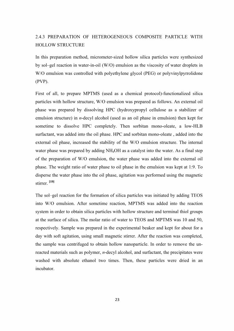
2.4.3 PREPARATION OF HETEROGENEOUS COMPOSITE PARTICLE WITH
HOLLOW STRUCTURE
In this preparation method, micrometer-sized hollow silica particles were synthesized
by sol–gel reaction in water-in-oil (W/O) emulsion as the viscosity of water droplets in
W/O emulsion was controlled with polyethylene glycol (PEG) or polyvinylpyrrolidone
(PVP).
First of all, to prepare MPTMS (used as a chemical protocol)-functionalized silica
particles with hollow structure, W/O emulsion was prepared as follows. An external oil
phase was prepared by dissolving HPC (hydroxypropyl cellulose as a stabilizer of
emulsion structure) in n-decyl alcohol (used as an oil phase in emulsion) then kept for
sometime to dissolve HPC completely. Then sorbitan mono-oleate, a low-HLB
surfactant, was added into the oil phase. HPC and sorbitan mono-oleate , added into the
external oil phase, increased the stability of the W/O emulsion structure. The internal
water phase was prepared by adding NH4OH as a catalyst into the water. As a final step
of the preparation of W/O emulsion, the water phase was added into the external oil
phase. The weight ratio of water phase to oil phase in the emulsion was kept at 1:9. To
disperse the water phase into the oil phase, agitation was performed using the magnetic
stirrer. [19]
The sol–gel reaction for the formation of silica particles was initiated by adding TEOS
into W/O emulsion. After sometime reaction, MPTMS was added into the reaction
system in order to obtain silica particles with hollow structure and terminal thiol groups
at the surface of silica. The molar ratio of water to TEOS and MPTMS was 10 and 50,
respectively. Sample was prepared in the experimental beaker and kept for about for a
day with soft agitation, using small magnetic stirrer. After the reaction was completed,
the sample was centrifuged to obtain hollow nanoparticle. In order to remove the un-
reacted materials such as polymer, n-decyl alcohol, and surfactant, the precipitates were
washed with absolute ethanol two times. Then, these particles were dried in an
incubator.
Page 33
24
To prepare silver shells on the hollow silica surface modified with thiol group, polyol
process was employed Silver nanoparticles were deposited on the silica surface as
follows: dry hollow silica particles functionalized with thiol group was dispersed
ethylene glycol. After completely dispersion PVP was added into the mixture. In order
to completely dissolve the PVP without a distortion of polymer chain, the mixture was
softly stirred with magnetic stirrer for 1 day. And then AgNO3 was dissolved in the
mixture. After all additives were completely dissolved the mixture solution was heated
with reflux.
Fig. 2.4.5 TEM images of hollow silica spheres functionalized with MPTMS at (A) 3.5
h, (B) 12 h, and (C) 24 h reaction time and (D) FE-SEM image of the same sample with
TEM image (C). [19]
It is well known that thiol groups attach to silver ions by the cleavage of an S–H bond
and the spontaneous formation of an S–Ag bond. As a result of unique behavior of thiol
groups containing sulfur atom, chemicals containing thiol groups have been widely used
as chemical protocols to make various metal–polymer and metal–metal oxide
composites. In addition, compounds containing sulfur, including metal sulfide such as
cadmium sulfide, are known as an excellent “adsorbent” for metal ions. Therefore, the
introduction of thiol groups by adding TEOS and MPTMS by stages is very important,
because they were used as a chemical protocol to deposit silver nanoparticles on the
silica surface. The reaction system is W/O emulsion in which water including the
ammonium hydroxide as a catalyst is dispersed in n-decanol as a form of droplet. TEOS
and MPTMS molecules as silica sources are dissolved into the continuous phase, n-
Page 34
25
decanol, because they are initially hydrophobic. When they are contacted with the
interface of water droplets containing ammonium hydroxide, sol–gel reaction of TEOS
and MPTMS molecules takes place. As a result, surface-modified hollow particles can
be synthesized by control of hydrolysis and condensation of TEOS and MPTMS at the
interface between water and n-decanol.
To coat hollow silica spheres with silver nanoparticles, polyol process was employed as
a reduction method for silver ions. The preparation steps of silver shell can be explained
as follows. At the first stage of the reaction, MPTMS-functionalized hollow silica
particles and PVP are dissolved into the ethylene glycol. After completely dissolution of
PVP, AgNO3 is added into the system. In this stage, some silver ions are bonded with
thiol groups of the silica surface by the cleavage of an S–H bond and the spontaneous
formation of an S–Ag bond. In the second in the second stage, Ag+ ions are reduced to
Ag0 metal state by ethylene glycol and PVP, and silver nuclei are formed and
immobilized on the surface of the MPTMS-functionalized hollow silica particles.
Finally, silver nanoparticles are formed on the silica surface by growth of nuclei as the
thermal energy is supplied to the system by heating at a given temperature.
Thus Hollow silica particles were synthesized through the sol–gel reaction by adding
the TEOS and MPTMS by stages into the W/O emulsion.
2.4.5 PREPARATION OF CORE – SHELL SILICA PARTICLE THROUGH
MICROEMULSION METHOD
The core-shell structures formation is also an another popular approach, which is
usually assisted by layer-by-layer (LBL) deposition [21-22] Monodispersed CdS–SiO2
core-shell particles ranging from nanometers (30–100 nm) to micrometers (1.5–2_m)
were prepared in situ in the nonionic reverse microemulsions [20] .After treating the
core-shell particles with concentric nitric acid, the hollow silica spheres were obtained
correspondingly. The study showed that the core size and shell thickness could be
tuned simply by controlling the addition amount of the reactants and the addition way
and that the hollow silica spheres could be potentially used as a novel class of catalyst
supports.
Page 35
26
Three microemulsions were used, and the reverse microemulsion system consisted of
NP – 7, n – butanol, cyclohexane and aqueous phase. Three microemulsios system
contained the composition but different aqueous phases: 0.2 mol l-1 Cd (NO3)2 solution,
0.2 mol l-1 Na2S solution and 25 wt% NH4OH solution, respectively. The Cd (NO3)2-,
Na2S- and NH4OH – containing microemulsions were designed as ME – 1, ME – 2 and
ME – 3, respectively. To guarantee the three systems stable, the weight ratios of
aqueous phase, NP – 7, n-butanol and cyclohexane were kept at 11:23:12:53. In order to
prepare the CdS–SiO2 core-shell particles, ME-1 was mixed with ME-2 with equal
volumes under stirring gently. After ageing for 2 h, ME-3 and TEOS were added
dropwise. After ageing for 24 h, acetone was added to demulsify the system, and the
particles were recovered by high-speeded centrifugation. To remove the impurity ions
and surfactant molecules, the particles were washed with water and alcohol at least for
five to six times in sequence, respectively, and then dried in vacuum at 60°C for 12 h. In
order to obtain the larger cores, seeding growth procedure was carried out. The small
CdS seeds were firstly prepared by mixing a small amount of ME-1 and ME-2. After an
appropriate interval for seeds maturation, a definite amount of ME-1 and ME-2 were
further added. The small CdS particles grew up into the desired size gradually. The
similar procedure was used to control the thickness of SiO2 shell. Firstly, a small
amount of ME-3 and TEOS were added to form the thin shell; and then, a definite
amount of ME-3 and TEOS were added.
Size of the CdS core was controlled through tuning the addition amount and the
addition way of the reactants. In order to prepare small CdS cores, ME-1 was mixed
directly with ME-2 with equal volumes under stirring vigorously. The Na2S- and
Cd(NO3)2-containing micelles collided and associated. During the process, the matter
exchanged simultaneously. The reactants reacted, nucleated and grew within the reverse
micelles. Because of the protection of the interface film, the conventional agglomeration
of the particles could be effectively refrained. The monodispersed particles could be
obtained. The CdS cores with average 5 nm in diameter were prepared by mixing
directly 5ml ME-1 and 5ml ME-2.
Seeding growth procedure was conducted to obtain the large cores. Small amount of
ME-1 and ME-2 were first mixed under stirring. After the small seeds were stabilized
Page 36
27
for a time, a definite amount of ME-1 and ME-2 were added alternately to make the
small cores grow into the desired large ones. During the process, the initially formed
CdS nanocrystals might act as the growth seeds, which provided with the nucleation and
growth sites; the reacting species added subsequently reacted and grew on the seed
surface into large crystals. Thus the core size could be controlled precisely by altering
the addition amount and the addition way of the reactants.
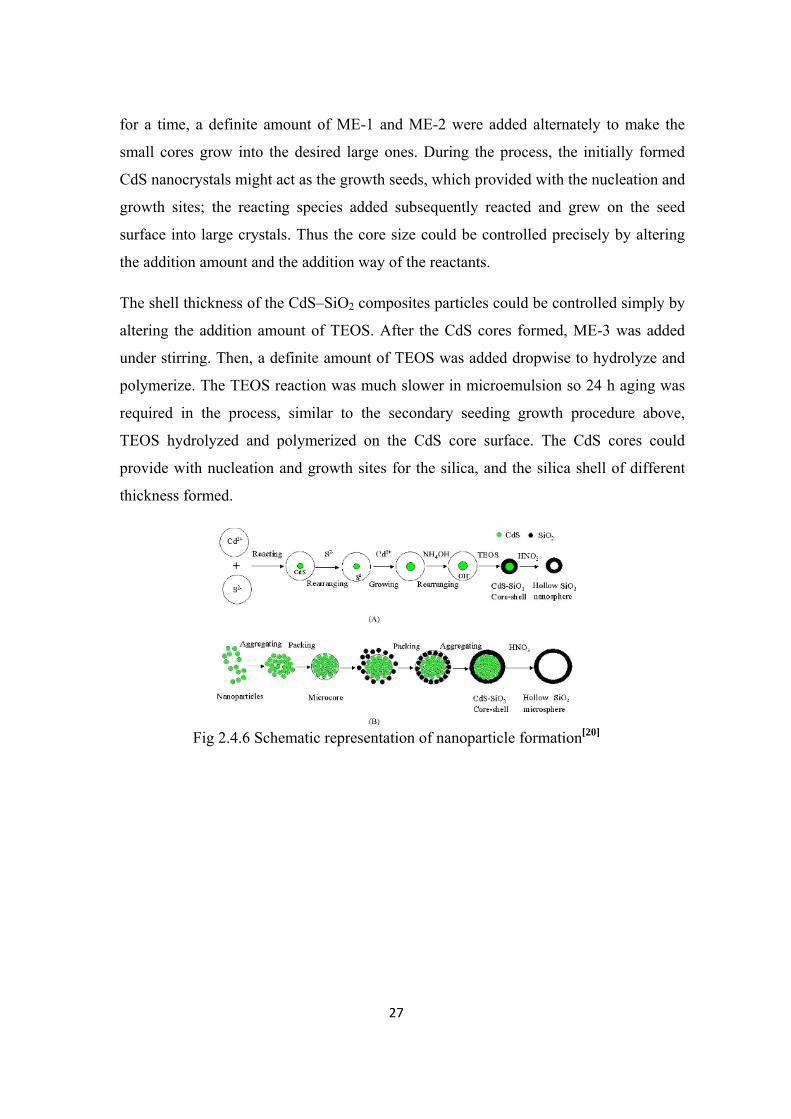
The shell thickness of the CdS–SiO2 composites particles could be controlled simply by
altering the addition amount of TEOS. After the CdS cores formed, ME-3 was added
under stirring. Then, a definite amount of TEOS was added dropwise to hydrolyze and
polymerize. The TEOS reaction was much slower in microemulsion so 24 h aging was
required in the process, similar to the secondary seeding growth procedure above,
TEOS hydrolyzed and polymerized on the CdS core surface. The CdS cores could
provide with nucleation and growth sites for the silica, and the silica shell of different
thickness formed.
Fig 2.4.6 Schematic representation of nanoparticle formation[20]
Page 37
28
2.5 OBJECTIVES OF THE PROJECT
The overall objective of the project is to prepare and study the formation of silica
nanoparticles, by varying the governing parameters like pH, Oil medium, water to
surfactant ratio (R) and others.
The specific objectives of this study are:
• To prepare microemulsions from different solutions with varying parameters
such as pH, medium etc
• To prepare and study nanoparticles from metals preferably silica in the
microemulsion
• To study the morphology of the nanoparticles by studying their formation and
size dependency characteristics.
• If possible prepare a hollow nanoparticle from the previously prepared
nanoparticles and study their characteristics.
Page 38
29
Chapter 3
EXPERIMENTAL PROCEDURE
Page 39
30
3.1 MATERIALS
In the experiment, all the chemicals were analytical grade and used without
purification. Tetraethyl orthosilicate (TEOS, Si(OEt)4) was used as a source of silica.
In all the experiments performed only ultra pure water (pH=7.00 and resistivity
18.3MΩ) is used.
Non-ionic surfactant-Triton X-100 [C14H22O(C2H4O)10] (chemical name-Glycol
Tertoctylphenyl ether) of scintillation grade, n-butanol, cyclohexane and aqueous
solution(Butyl amine or 25% ammonium hydroxide dissolved in water) were used as
surfactant, cosurfactant, continuous phase and dispersed phase, respectively.
Typically, a measured amount of surfactant and cosurfactant with weight ratio of 2:1
were dissolved in cyclohexane.
3.2 PROCEDURE
In this study, silica nano particles were synthesized in a water–oil (W/O) reverse
emulsion system. We focused on the effects of the pH value of aqueous droplets and
the R value. In particular, samples withdrawn at specific times from the nanoparticle
synthesis test tube are then characterized using optical microscope and finally under
scanning electron microscope (SEM). The combination of characterization techniques
revealed new aspects of the process of nano particle formation and structure, which
are discussed below. The experimental evidence obtained here is then discussed in the
relevant context.
First of all, as mentioned in the table 3.1 different pH aqueous solution of water and
ammonia or butylamine was prepared by using a digital pH meter. Table 3.1 shows
different composition of different pH solution.
Then, a specified volume of aqueous solution was taken and the surfactant TX–100
was added with different R values (table 4.2). Then butanol was added to the above
solution as co-surfactant (surfactant to co surfactant weight ratio 2:1). Then,
cyclohexane was added as oil phase to the solution. Then, the above prepared solution
was stirred continuously till the solution becomes transparent to the eye and then, the
Page 40
31
solution was left for some time, if the solution does not separate into two liquid layer ,
the prepared solution is stable.
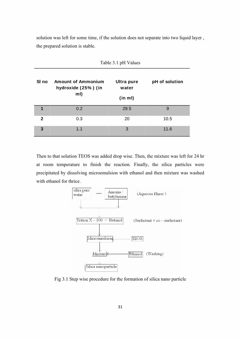
Table 3.1 pH Values
Sl no
Amount of Ammonium hydroxide (25%) (in
ml)
Ultra pure water
(in ml)
pH of solution
1 0.2 29.5 9
2 0.3 20 10.5
3 1.1 3 11.6
Then to that solution TEOS was added drop wise. Then, the mixture was left for 24 hr
at room temperature to finish the reaction. Finally, the silica particles were
precipitated by dissolving microemulsion with ethanol and then mixture was washed
with ethanol for thrice.
Fig 3.1 Step wise procedure for the formation of silica nano particle
Page 41
32
3.3 CHARACTERIZATION
Hund Weltzar with JVC-TK C1351 Optical Microscope of 4000X resolution was first
used to observe the formation of particles if any. Then, the nanoparticle morphology
was observed with images obtained from a JEOL model JSM-6480LV scanning
electron microscope (SEM), using a resolution at 5.9keV-133 eV and a drive
frequency of 39Hz. The samples were deposited on a thin brass film plate or film
circular in design of about 10mm diameter. The surface was smoothened using an
emery paper before the solution was added dropwise. Elemental analysis was
performed on a JESCO UV–vis-NIR spectrometer in a monomer-free 0.1 M TBAPF6
solution via incrementally increasing applied potential between 0.4 V and 1.2 V
Spectrophotometer, to study the presence of the particle formation by studying the
deflection of the UV rays in the path of the particles.
Page 42
33
Chapter 4
RESULTS AND DISCUSSION
Page 43
34
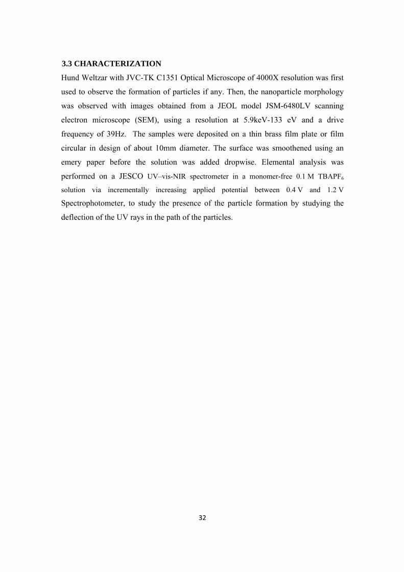
The results and data used for the preparation of nanoparticle are tabulated as shown below. The results obtained were compared on basically two important parameters i.e. keeping the R constant and keeping the pH constant. All other parameters apart from these were considered variable at any time apart from these two singularly.
Table 4.1 Material values at a constant R = 10
Sample no
Aqueous phase pH
Surfactant/
Co-Surfactant(w/w)
Water/TEOS
(molar ratio)
Water/oil
(v/v)
1 9 2 10 5
2 10.5 2 10 5
3 11.6 2 10 5
Table 4.2 Material values at a constant pH = 11.6
Sample no
R value
Surfactant /
Co- surfactant (w/w)
Water /TEOS (molar ratio)
Water/oil (v/v)
1 20 2 10 5
2 25 2 10 5
3 30 2 10 5
Upon addition of TEOS to the reverse micellar system, the formation of silica
particles involves a series of steps which can be identified as:
(i) Association of TEOS molecules with the reverse micelles
(ii) TEOS hydrolysis and formation of monomers
(iii) Nucleation
(iv) Particle growth
(v) Nuclei dissolution
(vi) Inter-micellar exchange of monomers
(vii) Ionization of monomers and
(viii) particle surface ionization.
Page 44
35
The association of TEOS molecules with the reverse micelles is viewed as a
distribution process. The partition of TEOS(step I) between the reverse micellar
pseudo phase (m) and the bulk oil phase (b) is considered to be brought about by the
formation of the monomer having one silica group (i.e. Si(OR)3OH), which is known
to be amphiphilic from interfacial tension measurements[37]. Further hydrolysis of this
species (step II) generates monomeric species with up to four silanol groups (i.e.
silicic acid). All these species (i.e. Si(OR)3(OH) to Si(OH)4) are designated as
‘monomers’, and are assumed to remain associated with the reverse micellar pseudo
phase due to their enhanced polar character. These species can participate in particle
nucleation and growth.
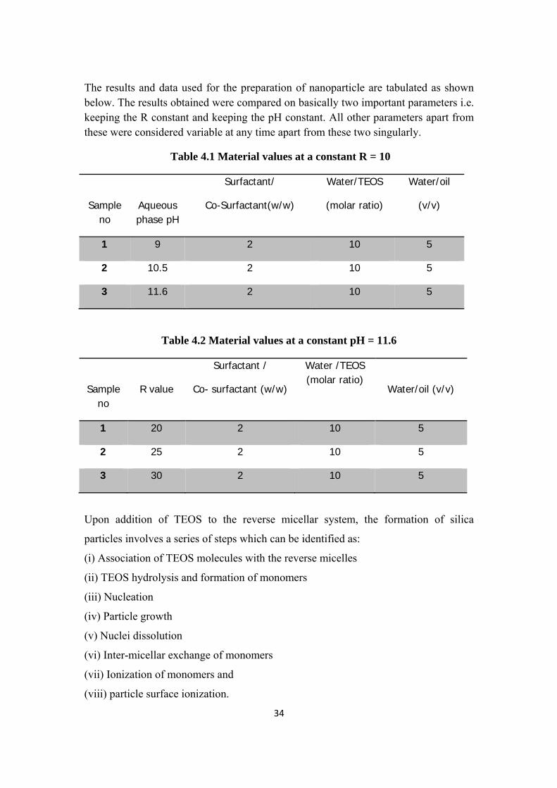
Fig 4.1 SEM images of a highly concentrated bunch of Si nanoparticles
The assumption that the monomers are confined to the reverse micellar pseudo phase
i.e. in a two-phase cyclohexane, water system, partially hydrolyzed TEOS species
partition preferentially into the aqueous phase. Nucleation involves the condensation
of monomers, and it can be an intra-micellar oriented-micellar event (step III). Particle
growth(step IV) may occur by addition of monomers to nuclei (an intra- or inter-
micellar process), or by aggregation of nuclei. Other possible events are nuclei
dissolution with generation of monomers (step V), monomer exchange by inter-
micellar collisions (step VI), monomer (silicic acid) ionization to produce anionic
species (step VII), and surface ionization to give charged silica particles (step VIII).
Page 45
36
(I) TEOS partition
Si(OR) 4 (b) Si(OR) 4(m)
Si(OR)4(m)+H2O(m) Si (OR)3(OH)(m) + ROH(m)
(II) Hydrolysis
Si (OR) 4 (b) + xH2O (m) Si (OR) 3-x(OH)x(m)+ xROH(m)
Si (OR) 3-x(OH)x+1(m) = “monomer”(m)
X= 1,2,3
(III) Nucleation
n. momoner(m) nucleus (m)
Monomer(m) + monomer(m`) ↔ nucleus(m or m`)
(IV) Particle Growth
monomer(m) + nucleus(m`) ↔ growth (momoner addition)
monomer(m) + nucleus(m) ↔ growth (momoner addition)
nucleus(m`) + nucleus(m) ↔ growth(nucleus aggregration)
(V) Nuclei Dissolution
nucleus (m) n.momoner(m)
(VI) Monomer Exchange
monomer(m) ↔ monomer(m`)
(VII) Monomer Ionization
Si(OH) 4(m) + y OH- ↔ SiOy (OH) 4-yy-(m) + yH2O(m) y= 1,2
(VIII) Surface Ionization
Si(OH)(s) SiO(s)
Page 46
37
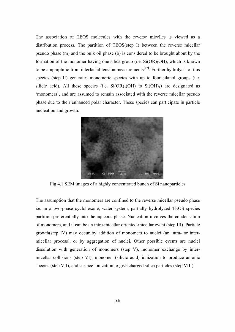
Fig 4.2 shows the SEM characterized nanoparticles synthesized at a pH value
controlled around 11
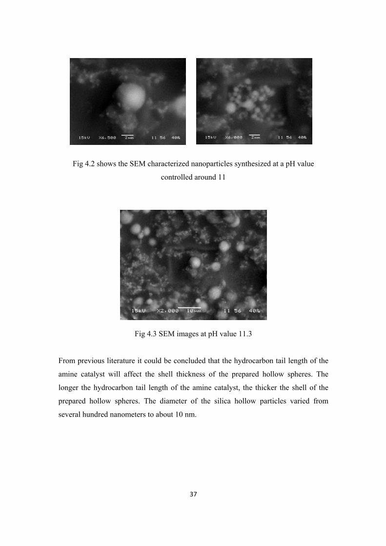
Fig 4.3 SEM images at pH value 11.3
From previous literature it could be concluded that the hydrocarbon tail length of the
amine catalyst will affect the shell thickness of the prepared hollow spheres. The
longer the hydrocarbon tail length of the amine catalyst, the thicker the shell of the
prepared hollow spheres. The diameter of the silica hollow particles varied from
several hundred nanometers to about 10 nm.
Page 47
38
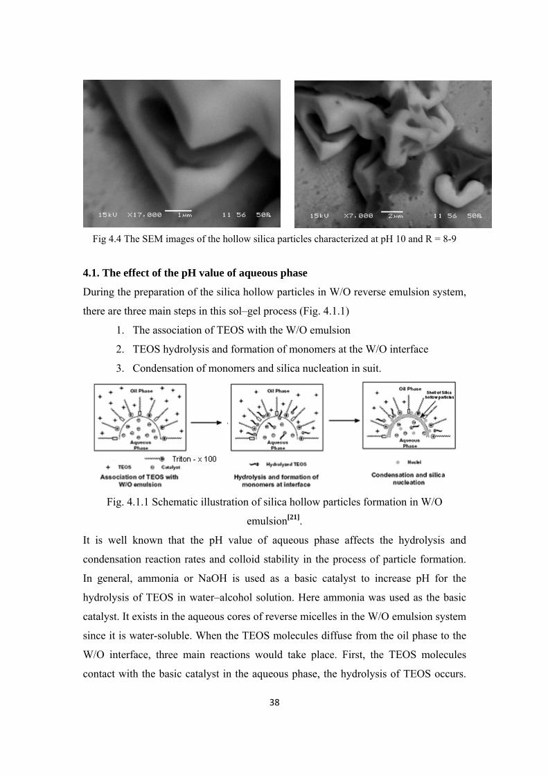
Fig 4.4 The SEM images of the hollow silica particles characterized at pH 10 and R = 8-9
4.1. The effect of the pH value of aqueous phase
During the preparation of the silica hollow particles in W/O reverse emulsion system,
there are three main steps in this sol–gel process (Fig. 4.1.1)
1. The association of TEOS with the W/O emulsion
2. TEOS hydrolysis and formation of monomers at the W/O interface
3. Condensation of monomers and silica nucleation in suit.
Fig. 4.1.1 Schematic illustration of silica hollow particles formation in W/O
emulsion[21].
It is well known that the pH value of aqueous phase affects the hydrolysis and
condensation reaction rates and colloid stability in the process of particle formation.
In general, ammonia or NaOH is used as a basic catalyst to increase pH for the
hydrolysis of TEOS in water–alcohol solution. Here ammonia was used as the basic
catalyst. It exists in the aqueous cores of reverse micelles in the W/O emulsion system
since it is water-soluble. When the TEOS molecules diffuse from the oil phase to the
W/O interface, three main reactions would take place. First, the TEOS molecules
contact with the basic catalyst in the aqueous phase, the hydrolysis of TEOS occurs.
Page 48
39
Then the hydrolyzed TEOS molecules will condensate at the interface. At the same
time, the polycondensate silica will depolymerize under the existing of base catalyst.
Finally, the resultant negatively charged silicates and the ammonium cation of TX-
100 steadily self-assemble at the interface to form a silica shell. It is well-known that
the hydrolysis rate of TEOS will increase with the pH value of the aqueous phase
when the base is used as the catalyst. While the rate of condensation will reach a peak
at neutral environment then decrease with the continually increase of the pH value. At
the same time, the rate of depolymerization almost keeps constant when the pH is
over 7 [35].
(a) (b)
Fig 4.1.2 Effect of pH on particle size (a) pH=9-10 (b) pH>11
The competition of hydrolysis, condensation and depolymerization will determine the
nucleation and the growth position of silica nuclei in the reverse emulsion system.
When the pH is over 10, the rate of condensation will be slower than that of
hydrolysis and depolymerization[36]. So the nuclei mainly occurred at aqueous
droplets and nanoparticles were obtained finally as shown in Fig. 4.1. Whereas, when
the pH was controlled near the neutral, the condensation reaction will be quicker than
the hydrolysis, the hydrolyzed TEOS molecules will condensate at the interface
rapidly and in the end, silica particles were prepared as shown in Fig. 4.1.2.
Page 49
40
4.2. The role of butylamine/ammonia as base catalyst
As discussed above, the pH value of the aqueous phase will affect the morphology of
silica particles. To control the pH value of an emulsion system, amine is a good
choice. Compared with ammonia or NaOH, the types of amine are very ample and
they are commercial available widely. The relative strength of amine base is usually
expressed as either pKb or pKa of the conjugate acid [37]. The strong base has a low
pKb value. In our experiments, ammonia (pKb = 4.75), butylamine (pKb = 3.39) were
used to catalyze the hydrolysis and the condensation of TEOS in W/O emulsion. The
key factor was the pH of aqueous droplets otherwise the relative strength of base. This
phenomenon is also believed to relate with the competition among the three reactions
of the sol–gel process. It is obvious that the increase of OH- ions causes an increase in
the rate of hydrolysis of TEOS molecules, hence a large number of monomers are
produced. Micelle and intramicellar nucleation will occur when the number of
monomers inside the aqueous core exceeds a critical value. And the ethanol as a
hydrolysis byproduct also enhances the nuclei formation by increasing the fluidity of
the interface and the intermicellar exchange rate.
4.3 Effect of R value
In general particle sizes depend on water-to-surfactant ratio assuming constant
aggregation number [38, 39]. However, the dynamics model of microemulsion system
allow water droplets to continuously collide and coalesce in a diffusion process that
promotes increase in droplet sizes and it drives the reactants through the interface due
to the local ionic strength. Water-to-surfactant ratio (R) and ionic strength affect the
rigidity of the interface and the reaction kinetics [40, 41] providing large particle
formation. Sizes of particles do not increase as R increases from 8 to 10. Nevertheless
at R=10 there are larger particles and a distribution in sizes. Silica particles from
TEOS hydrolysis in Triton X-100-cyclohexane-ammonium hydroxide microemulsions
of 50±70 nm range were observed. Particle size increases as R increases. Upon
increasing the surfactant concentration there is an increase in the population of the
host reverse micelles in the organic phase. Higher nanoparticle uptake increased the
rate of collisions and the probability of aggregation between nanoparticle-populated
reverse micelles, which led to the formation of larger particles.
Page 50
41
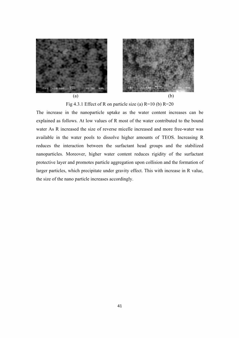
(a) (b)
Fig 4.3.1 Effect of R on particle size (a) R=10 (b) R=20
The increase in the nanoparticle uptake as the water content increases can be
explained as follows. At low values of R most of the water contributed to the bound
water As R increased the size of reverse micelle increased and more free-water was
available in the water pools to dissolve higher amounts of TEOS. Increasing R
reduces the interaction between the surfactant head groups and the stabilized
nanoparticles. Moreover, higher water content reduces rigidity of the surfactant
protective layer and promotes particle aggregation upon collision and the formation of
larger particles, which precipitate under gravity effect. This with increase in R value,
the size of the nano particle increases accordingly.
Page 51
42
Chapter 5
CONCLUSION
Page 52
43
There have been many methods employed to synthesize silica nanoparticles. Using
different methods, the obtained nanoparticles show significant difference in both
particle diameter and morphology. Thus, the choice of synthetic methods in the
synthetic process depends on the materials applications requirement. For example,
small particles are desirable in catalysis where the main emphasis is on surface-to-
volume ratio, whereas larger particles are often necessary for optical applications.
Silica nanoparticles with size below 10 nm have been prepared by traditional chemical
methods, however the tiny particles tend to grow and aggregate into large particles.
The major problems for non-traditional physical methods are its high cost; the
obtained nanoparticles also have a wide particle size distribution. In microemulsion,
the nucleation and growth of particles are restricted within the water core of inverse
micelles. Thus, microemulsion method is often used to synthesize nanoparticles with
specific size and morphology. The advantage of the method is the ability to control
the particle size and morphology easily by adjusting the concerned parameters, e.g.,
the concentration and type of surfactant, the type of continuous phase, the
concentration of precursors and molar ratio of water to surfactant.
Silica nanoparticles were successfully prepared in a W/O reverse emulsion through
control of the sol–gel process reaction environment. The following conclusions can be
drawn from this work
• when the pH value of aqueous phase exceeded 10, the rate of hydrolysis and
polymerization was quicker than that of condensation, granular or irregular
shape particles formed
• when the pH was controlled around 8–9, silica nanoparticles were prepared
• Water-soluble amines were effective catalysts to fabricate a silica hollow
structure. The longer the hydrocarbon tail, the thicker the shell of the hollow
particles
• R ratio is found to be directly influencing the size of the nanoparticles.
Page 53
44
In summary, the proper pH value of water phase, viscosity of outer oil phase, water to
surfactant ratio were the crucial factors to the formation of the hollow structure.
Although significant advances have been made in preparation of silica nanoparticles,
we are also faced some problems. One challenge is to prepare colloidal nanoparticles
with high stability and good exchangeability of solvents. It is an important process to
transfer silica nanoparticles to different chemico-physical environments in practical
applications. Another one is to fabricate size-controlled or shape-controlled and
chemically clean silica nanoparticles with narrow size distribution, which are easily
incorporated into a variety of substances to form nanocomposites or assembled into
higher-order nanostructures. In addition, it is an important goal for advanced projects
to prepare three-dimensional nanomaterials with controlled geometry and structure.
Besides theoretical and experimental studies on the novel synthetic technologies and
the important influence factors, the combination of traditional and non-traditional
methods needs much further attention.
Page 54
45
REFERNCES
1. Nanostructure and nanomaterials , synthesis, properties and application by
Guozhong Cao, University of Wasington, USA.
2. A practical method to production of hollow carbon onion particle, C. He et al. ,
journal of alloy compounds 425(2006) 329 – 333.
3. Recent advances in nanoparticle synthesis with reversed micelles, J Eastoe et
al., Advances n Colloidal and Interface Science 128 – 130 (2006) 5 – 15.
4. Bommarius AS, Holzawarth Jf, Wang DIC, Hatton TA, Physical Chemistry,
34(1990),1232.
5. Rojas S, Garcia Garcia FJ, Applied catalysis A generation (2005)285;24.
6. National nanotechnology initiative 2000 leading to the next industrial
revolution, A report by interagency working group in nanoscience,
engineering and technology http://www.nano.gov.
7. New reactor for production of tungsten disulfide hollow onion – like
nanoparticle Y. Feldman et al. , solid satate science 2 (2000)663 – 672..
8. The fabrication of hollow spherical copper sulfide nanoparticle assemblies with 2 –
hydroxyprpeyl – β – cyclodextrine as a templet under sonication J – Z Xu et al. ,
Ultrasonics Sonochemistry 13 ( 2006)451 – 454.
9. Nanosized aluminum nitride hollow spheres formed through a self timplating
solid – gas interface reaction , J. Zheng et al. , journal of solid state chemistry
180 (2007)276 – 283.
10. A facile colloidal templating method to monodispersed hollow Ag and Ag/Au
subnicrometer spheres J. Zhang et al., Material letters 60 (2006)280 – 283.
11. Flower like bundles of ZnO nanosheeets as an intermediate between hollow
nanoshpere and nanoparticles, A Eftekhari et al. material science and
engineering A 437 (2006) 446 – 450.
12. A simple approach to synthesize KNiF3 hollow spheres by solvothermal
method M. Zhang et al., material chemistry and physics 89 (2005)373 – 378.
Page 55
46
13. A comparative study of the microemulsion and interfacial polymerization for
polyindole S. A et al, material letters 88(2007)340-345.
14. Direct preparation of hollow silica spheres in a water in oil emulsion system L.
Song et al. journal of non-crystalline solids 352 (2006) 2230 - 2235.
15. Gold nanoparticle encapsulating horseradish peroxide R. kumar et al. 26(2006)
6743 – 6753.
16. Silica – PMMA core – shell and hollow nanosperes, K. Zhang et al., colloidal
and surface A: phyicochem. Engineering aspects 277 (2006)145 – 150.
17. An emulsion preparation for novel micro-porous polymeric hemi-shells,
K.Naidoo et al., Materials letters 289 (2004) 160-164.
18. Development of an immobilization method by encapsulating inorganic salt
forming hollow microspheres, H. B Ji et al , catalysis today 105 (2005)605 –
611.
19. Facile and novel route for preparation of silica/silver heterogeneous
composite particles with hollow structure, J. M Lee et al., colloids and surface
A: phyicochem. Engineering Aspects 301(2007)48 – 54.
20. Preparation of CdS – SiO2 core – shell particles and hollow SiO2 spheres
ranging from nano meters to microns the noninonic reverse microemulsion, F
Teng et al., catalysis today 93 – 95 (2004) 651 – 657.