53
PREPARING FOR A DRILLING PROJECT A CONTRACTOR’S PERSPECTIVE BY: PAUL BALEMI CONTRACTORS LTD

PREPARING FOR A
DRILLING PROJECT
A CONTRACTOR’S PERSPECTIVE
BY:
PAUL BALEMI
CONTRACTORS LTD
PLANNING A DIRECTIONAL DRILL SHOT
IN AN URBAN ENVIRONMENT
INSTALLATION BY INTELLIGENT
DIRECTIONAL DRILLING METHODS

PLANNING A DIRECTIONAL DRILL
SHOT IN AN URBAN ENVIRONMENT
FIRST CONSIDERATION:
• THE SIZE OF DRILL RIG REQUIRED
• SITE CONSTRAINTS
• WHICH METHODOLOGY SHOULD BE USED
• TYPE OF PIPE TO BE INSTALLED
• OPTIONAL MACHINES WITH DIRECTIONAL
STEERING OPTIONS
• GROUND CONDITONS

A GUIDE FOR THE SIZE OF DRILL RIG
REQUIRED
• The diameter and length of pipe to be installed.
Diameter (mm) 50 100 150 200 250 300
110 3000 4000 - - - -
125 3300 4500 5000 - - -
160 4000 5000 6000 7000 - -
180 4250 5500 7000 8000 - -
225 450 6000 7500 9000 11000 -
250 4750 6500 8250 10000 12000 15000
280 5000 7000 9000 12000 14000 19000
315 5500 8000 10000 12500 15000 20000
355 6000 9000 12000 15000 20000 25000
400 10000 15000 20000 25000 30000 40000
450 17000 20000 25000 35000 48000 65000
500 20000 28000 35000 50000 65000 90000
630 25000 35000 50000 68000 88000 100000
The above figures are based on a backcut diameter recommended as 1.5 x pipe diameter
Directional Drilling - Installation & Pullback Pressure (lbs Force)
Length (m)

SITE CONSTRAINTS
• SPACE AVAILABLE FOR SET UP
For the size of the machine required plus any
mud handling equipment
To weld pipe string and install the pipe.
Lead in length required for pilot bore to
obtain correct grade and correct alignment.
Is a blind shot an option.

Maxi Rig Set Up


Transportation of Pipe String

RESTRICTED
SITES

Lead in length required for pilot bore to
obtain correct grade and correct alignment.

OBSTRUCTIONS TO BE TAKEN INTO
ACCOUNT FOR SET UP
– Traffic control and
pedestrian access.
– Other utilities
overhead and
underground.
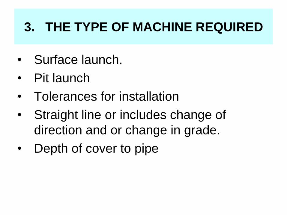
3. THE TYPE OF MACHINE REQUIRED
• Surface launch.
• Pit launch
• Tolerances for installation
• Straight line or includes change of
direction and or change in grade.
• Depth of cover to pipe

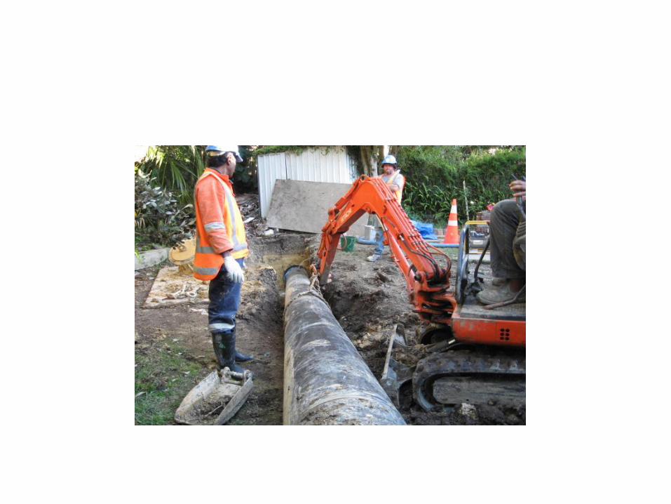
• SURFACE LAUNCH

Laser Guided Pit Bore Machine

Pit Launch Machine
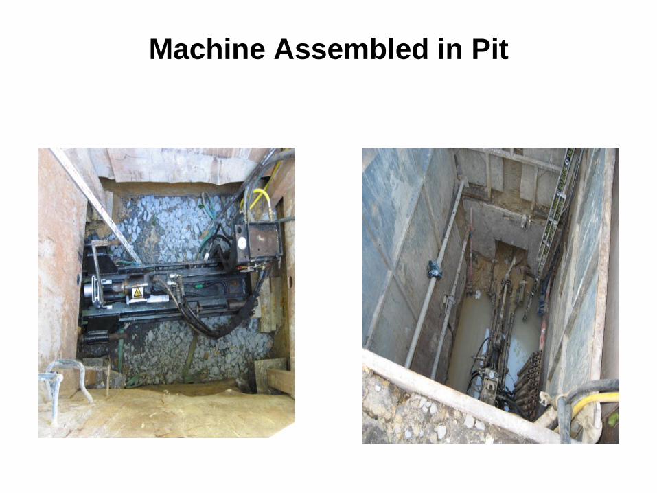
Machine Assembled in Pit
4. TYPE OF PIPE TO BE INSTALLED
P.E.
PVC
CERAMIC
CONCRETE
STEEL

P.E.
Advantages:
• Long lengths welded into a single strings to
allow continuous pulling operation, flexible to
allow to accommodate lead in and stringing.
• Can be made in short lengths with mechanical
joints (push lock fit) for straight bores.
• Lightweight
Disadvantages:
• Area required to weld long string. May have to
be transported to rig at time of pull back.

PE pipe


PVC
Advantages:
• Straight rigid lengths for more accurate grade to finished pipe.
• Short lengths available in restrained joint up to 150 diameter.
• Lightweight
• Butt Welded – Fusible PVC
Disadvantages:
• Less flexible than PE pipe for lead in more suitable for straight shots.
• Not available in sizes above 400mm.

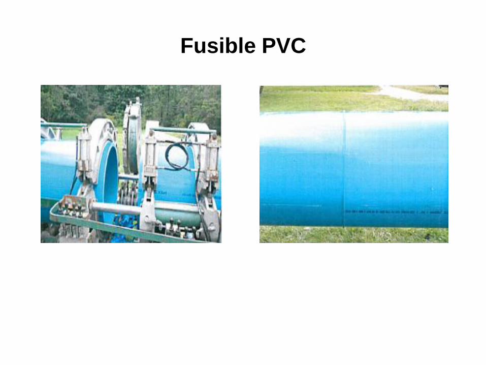
Fusible PVC

CERAMIC
Advantages:
• Good Strength with higher load specifications for shallow depths requirements.
• Ideal for straight shots.
Disadvantages:
• Only suitable for straight shots.
• More installation time.
• More expensive

CONCRETE
• Advantages:
• Good range of diameters including larger sizes.
• Good Strength
• Price
• Disadvantages:
• Straight shots required.
• Shorter lengths, more joints.
• More installation time required.

STEEL
Advantages:
• Good strength
• Can also be rammed through unstable or loose
rock and cobbles.
• Variable lengths available.
Disadvantages
• Less flexibility, more suited to straight bores.
• Cost and time to weld.

5. OPTIONAL MACHINES WITH
DIRECTIONAL DRILLING STEERING
OPTIONS
1. STRAIGHT BORE LASER GUIDED PIT
MACHINE.
2. PIT MACHINE WITH WALKOVER
STEERING SYSTEM.

STRAIGHT BORE LASER GUIDED PIT
MACHINE
Advantages
• Very accurate bores.
• Minimum backream size 20-25mm larger than pipe.
• Big thrust capacity for size of rig.
• Suited to confined space sites.
• Short lengths of pipe can be installed.
• Blind Shots.
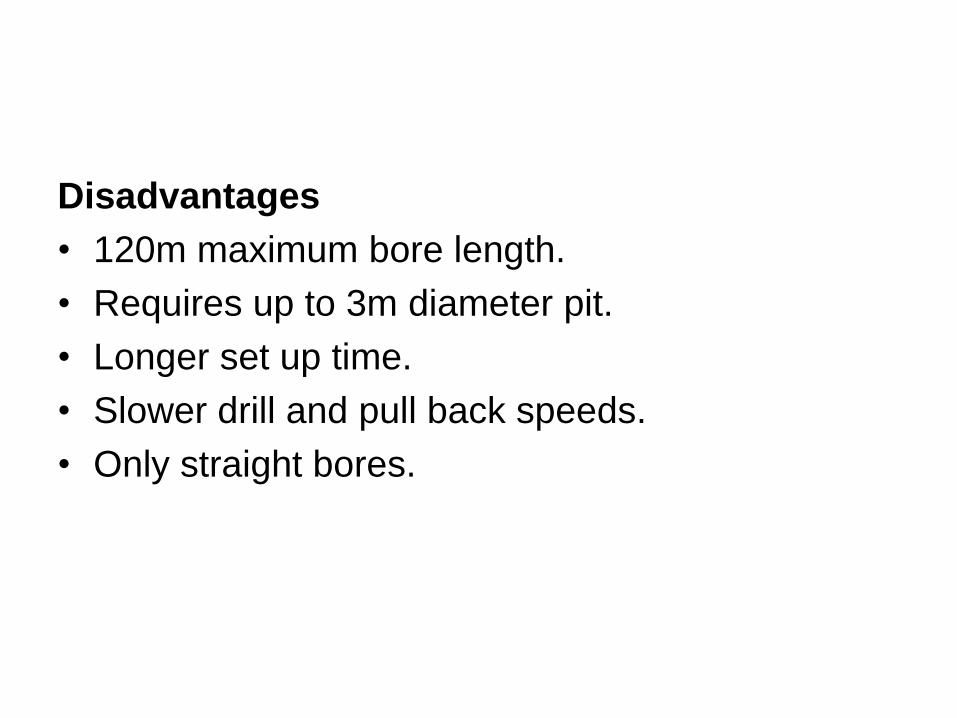
Disadvantages
• 120m maximum bore length.
• Requires up to 3m diameter pit.
• Longer set up time.
• Slower drill and pull back speeds.
• Only straight bores.


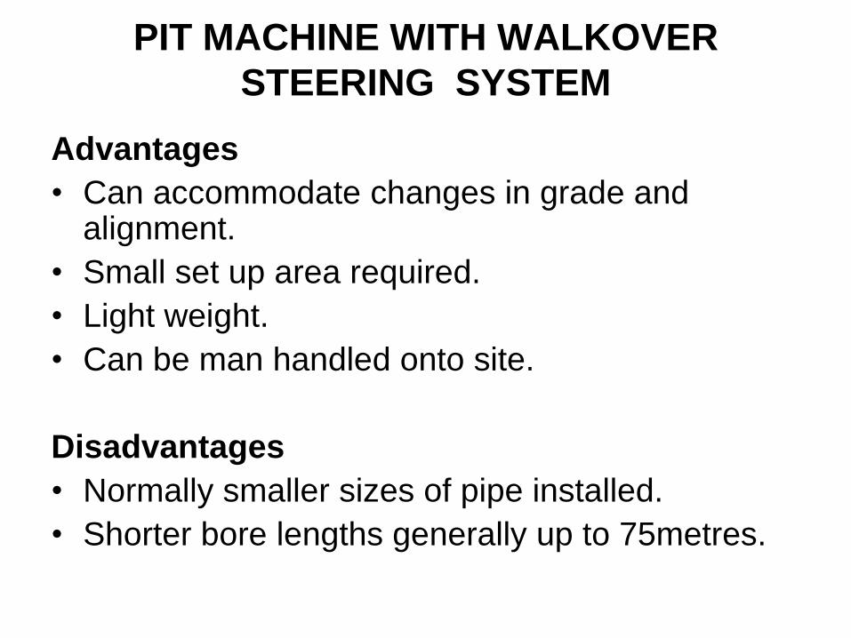
Advantages
• Can accommodate changes in grade and alignment.
• Small set up area required.
• Light weight.
• Can be man handled onto site.
Disadvantages
• Normally smaller sizes of pipe installed.
• Shorter bore lengths generally up to 75metres.
PIT MACHINE WITH WALKOVER
STEERING SYSTEM


INSTALLATION BY
INTELLIGENT DIRECTIONAL
DRILLING METHODS

METHODS CONSIST OF THE
FOLLOWING:
Locate All of Other Underground Services In or
Near the Bore Path
Pre Plan the Bore Shot
Determine the Best Location System that will
suit the job.
Check ground conditions to be encountered.
The logs sheets results from piloting and or
backreaming
The drillers log sheet records
Correct pullback speed

Locate All of Other Underground
Services In or Near the Bore Path
• Surface Detection
Locating by Cable Detectors
Underground Radar.
Marking out from maps.
Pilot for Services
CCTV Laterals

Determine Accuracy of Mapping Records
• Vacuum excavation with sucker truck and jetting.
• Excavation of pilot holes – by hand around
service or by photographs.
• Location of sewer or storm water laterals using
CCTV with sonde to detect depth and position.

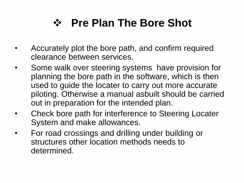
Pre Plan The Bore Shot
• Accurately plot the bore path, and confirm required clearance between services.
• Some walk over steering systems have provision for planning the bore path in the software, which is then used to guide the locater to carry out more accurate piloting. Otherwise a manual asbuilt should be carried out in preparation for the intended plan.
• Check bore path for interference to Steering Locater System and make allowances.
• For road crossings and drilling under building or structures other location methods needs to determined.

Determine the Best Location System
that will suit the job.
• The Walkover in Ground Positioning
System
• The Magnetic Wired Steering System
• Gyroscope Navigation Guidance System.
• Laser Guided System

Bore plan must include the ground
conditions to be encountered
• Field inspection of the ground conditions.
• Ground conditions must be monitored whilst
pilot boring. i.e. Rotation and thrust pressure
will confirm the designed mud plan is correct or
needs adjusting to achieve desired results.
• Pre reaming before pipe installation will also
confirm mud design is correct for pipe
installation.


The log sheet results from piloting
and or backreaming
• The log sheet results from piloting and or
backreaming must be used to pre- plan the
drillers mud design – pressure and speed of
pullback for pipe installation.

The drillers log sheet records
1. The drillers log sheet records are the most important Quality Assurance Control for correct installation. The pullback speed must be controlled to match the mudflow. Bore hole diameter less the pipe volume over the flow rate of the drill rig mud pump equals the speed of pullback.
Borehole Volume (Ltr) – Pipe Volume(Ltr)
Mud Pump Capacity (Ltr/min.)

Drillers Log SheetsJB CONTRACTORS LTD
DIRECTIONAL DRILLING QUALITY ASSURANCE
PILOT BORE/ BACK REAM / PIPE INSTALLATION
CLIENT DATE
SITE ADDRESS JB JOB NO.
DRILL ENGINEER PIPE DESCRIPTION
OPERATOR LENGTH OF BORE
LOCATOR MACHINE
PULL BACK SPEED - TIME PER ROD BACK REAM SIZES
PLANNED WATER POLYMER BENTONITE ROD TIME
Rod No. Start Log
Stop
Operation
Rotation
Pressure
Pull Back
Pressure
Water
Quantity
Water
Pressure Ground condition, comments

Correct pullback speed
• Too Fast
– Possible Hydrolock
– Mud frackout due to extra downhole pressure
– Lack of mudflow to pipe lead end resulting in voids around the pipe.
• Too Slow
– Mud washout from around the pipe leading to future voids.


