34
• I X-564-72-65 PREPRiNT https://ntrs.nasa.gov/search.jsp?R=19720015507 2018-06-05T21:15:56+00:00Z
• I
X-564-72-65PREPRiNT
https://ntrs.nasa.gov/search.jsp?R=19720015507 2018-06-05T21:15:56+00:00Z

PROGRAM DOCIJqMENTATION STANDARDS
_! Donald A. Parker:'_' Information Processing Division
- _ Goddard Space Flight Center
,%
_ ClintonA. Frum
Computer Science Corporation
._ Silver Spring, Maryland
March 1972
GODDARD SPACE FLIGHT CENTF, RGreenbelt, Maryland
'l
1972015507-002

j-
J4"
,',%
._ PREC:,']DINGPAL,_ BL/hNK NOT _-_MED.:£
AC KANOWLEDGEMENTS
I would like to express my thanks to Carol Mannan*,Karen Hillman_ and Orbie Jones for their cooperationand assistance in the preparation of tais document.
5
.-.'.
.,
: "-" 7/--"
*Computer Science Corporation employees.
1972015507-003
j.-
/..
•%
:: -_. .I_ING PAGE 13L.,_-_,L__'OTPI_.R_
_, ABSTRACT
'I'_v style manual has been developed to serve as _. refere_.ce and gnflcle-: for system .and program documentation. It is intended to set s;:andards for doc-
umentation, prescribing the procedures to be followed, format to be used, and
•: -..: ._..: iniorrnation to be produced.
. : The standards for program documentation specify the extent tc which the" programmer sho_.d support his efforts in writing.
There are several excellent reasons for the necessity of clear and accu-rate documentation:
• It _ssists the program development process, saving rewrite time, andserves as a stepping stone to further program modification of pro-grams currently operational.
• It assists in converting prcgram.s to a new machine, i.e., in the caseof obsolete equipment.
• It provides programmer recognition.
• I_:serves es a record of the work performed.
• It increases the efficiency of the eutire installation,
• It provides the program users _Ith a basic understanding of the pro-
if gram and of the _pes of formulae, controls, etc., that are included._:::..i It also clarifies the purposes and o_.'tputs of the program.
Documentation users may be interested in programs frc,m several pointsof view. Programmers who modify and update programs require the most ex-
tensive descriptionofa program. Management,on theotherhand,isoftenin-
_ terestedinonlya generaldescriptionoftheprogram'sfunction,forpurposesofreview.Operatorsareinto.restedina concisedescript_.onoftheprogramoper-atinginstructionsand error recovery procedurestc,enablethem toeffectively
:_': run programs. Program users are interested in a technical description of the_i_- program, itsinputand output,toenablethem tosetup runs and interpretthe': '_ reaults.
-_...,.V
1972015507-004

.j-
This standards manual describes several aspects of programdocumentafiQn:
• Syster_': Descx_iption _
® Program Description
:t
Op_,'ation Description
• Machine Utilization
_ Program Validation
The first three sections of the manual (_stemo ProgTam, and Operation de-,. scriptions) contain information of particular interest t.o ma.-agement, operators,
• _ and program users, respectively. The information in these three sections may
7, tend to be x epetitive in some respects, but each section has been designed as a< self-sufficient description from the management, operator, or user point of,: view,
J *Notto be confuNd withOlmtatin8 Systems.
vt
1972015507-005

7
{
TABLE OF CONTENTS
Page
SectionI - System Description ...................... I-I
1.1 TitlePage .............................. l-1>
I.2 i_ogram Sign-OffSheet ....................... 1-11.3 RevisionPage ............................. 1-1
• i.4 Table of Contents ........................... I-51o 5 Scope and Purpose .......................... 1-5 {1.6 Authority ............................... 1-5 _1o 7 Problem Definition .......................... 1-6
1.8 Problem A_nalysis ........................... 1-6
Section 2 - Prograa-n Description 2
• 2.1 Program Summary .......................... 2-12.2 Program Logic and Flow ....................... 2-12.3 Technical Description ......................... 2-22.4 Input ................................. 2--2
• 2 5 Internal Data Areas Description 2 22 6 Output 2 v.
• _" 2 7 Controls and Constraints 2 5
/ 2.8 Program Listing and Flow Chax'ts .................. 2-7
' Section 3 Operation Description 3 1"" -- • • • t db • • e • • • • • • • • • • • • • --
• 3 1 Operational Data Flow :3 1,_ • • • c o • • • • • • • • a • • • • • • a • • • •
.:: 3.2 Machine Set-Up ............................ 3-1:_. 3 3 Input Set Up 3 1• _ • • • • _ • • • • a _ • a _ a • • • J a • • • _ • • • • • • --
:3.4 Operator Instructions ......................... 3-I
:3.5 Disposition of Output ......................... 3-53.6 Restart Procedure ......... , .... , ........... 3-5
3.7 Program Fault Identification ........... , ......... 3-5' 3 7 1 Halts 3 5• • • • • • • • o • o • • @ • • _' • • • • • • • o • • B ,* • • --
7 2 Messages 3 6• • • • B • • • _ • • • • • • • • • • • • _ • • • • a • • --
_ 3.7.3 Console Alteration/sense Switches/Alter Keys ....... 3-6';' 3.7.4 Operating Manual/Layouts ................. 3-6
Section 4 - Machine Utilization ....................... 4-1
4.1 Program Language ............... , ...... , , . . 4-1
• (¢
1972015507-006

TABLE OF CONTENTS (Cont'd)
4. z Operat_ System and Version .................... 4-14.3 Memory and Equipment Usage ................. . . . 4-1
, _.. 4 Program Run Time .......................... 4-I
•_ Section 5 - Program Validation ........................ 5-1
5.1 Statement of Method ......................... 5-I
5.2 D_ Set for input and Description .................. 5 -i: 5 3 Program Output and Description 5-2¢ • • • ¢ • • • $ • • • p • • • • o • •
_ Section 6 - A_ ............................ 6-I
), ,
2_
1972015507-007

• ', , .
SECTION I
SYSTLId DESCRIPTION
v
1.1 TITLE PAGE
The title page should precede each system description, and should in-( clude the following i_ems:
,. • Program name
i; • User name, address, and control number:''' •4
_: • Programmer/An_yst name, title, and organization
iii ;.ii• .i • Date of publicat'to_• • Revision nur.aber
,. • Approver's "rome (Technical Monitor or his designated representative)
_! 1,2 PROGRAM SIGN-OFF SHEET4;"Je% '_'.'
_ "_•: _ should include a list of people (denoted by their signature's) who mvst approve,,., The program sign--_ff sheet should immediately follow the title page, and
A sample program sign-off sneet io found on page 1-3.
t I.3 REVISION PAGE
and should be kept current, indicating the dates of all revisions made to the doc-
I_ment. It should include the followll_ Items:
:_ • Program dispositionstatus
, 1-1
1972015507-008

TITLE PAGE
RF.PROCESSING REPORT PROGRAM
Prepared For
Bernard Narrow>
, Goddard Space Flight Center4
":i Greenbeit, Maryland
_:_ Control No. 8654
"'l
"ill Prepared By", Leon C ariaga
i, Programmer/Analyst
CSC
April ]5, 1970
_ Revision No. 1
4
APPROVED BY:
¢
t
_, 1-2i
1972015507-009

f
,:1:_.
PRo?Of{AM SIGN-OFF SHEET
/ QUALITY CONTROL:
"_', OPERATIONS:
: _ ENGINEERING:
_' BRANCH:
•
_ O'£HER (USER):
i-i
"); ,
'?c
1-3
1972015507-010

f I
o_
IZi
:i
_, 1-4
1972015507-011
f
• -.,. :" *
., .. .
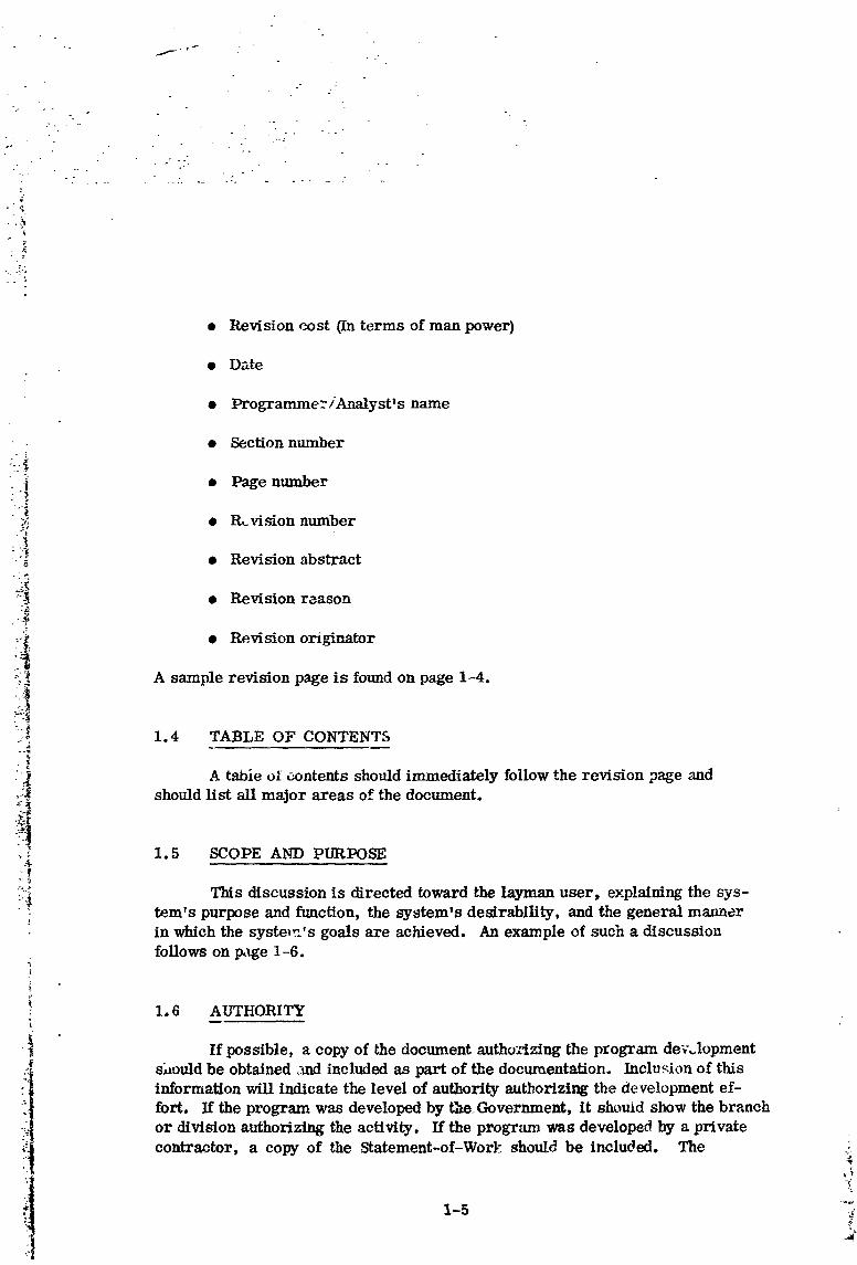
• Revision cost (In terms of man power)
• Date°
• Programmer/Analyst's name
• Section number
_! • Page number
"?i • P_visionnumber
• _ • Revision abstract
:2_ • Revision reason-rz.i
3
:-_ • Revision originator
-_ A sample revision page is found on page 1-4.
?i..-_ 1.4 TABLE OF CONTENTS
:.i_ A table ol contents should immediately follow the revision page and_._ should list all major areas of the document.
,_, 1.5 SCOPE AND PURI_SE
: _ This discussion is directed toward the layman user, explaining the s_ys-::i_ fern's purpose and function, the _jstem's desirability, and the general manner
in which the systmr.'s goals are achieved. An example of such a discussionfollows on page 1-6.
1,6 AUTHORITY
•i If possible, a copy of the document _mtho':tzing the pIogram dev,.lopment
_i shouldbe obtained,mclincludedas partof thedocumentation.Inclusionof thisinformation will indicate the level of authority authorizing the. development ef-
fort, If the program was developed by the Government, it shouid show the branchor division authorizing the activity. If the program was developed by a privatecontractor,a copy of the Statement-of-Workshouldbe included. The
1-5 i_
:.I k
]9720]5507-0]2

SCOPE AND PURPOSE
The use of large d_ta bases involves considerableproblems. Their creation is subject to a large range
of errors, and often they must be periodically supple-mented _ith new information in order to retain their
utility. "l%efollowing program is designed to assist
• : the user in maintaining large files stored on magnetic, tape, provided the file format adheres to certain
restrictions. All entries in the file must be identical
in format and must be written in fixed-length blocks
• on the magnetic tape. The file also must contain no": duplicate entries. In any one use of the program, the-_ ' user may add a new set of entries to an existing file,
-:. dete_Ane those entries not meeting user-specified: restrictions, and/or correct (replace or delete) in&i-• vidual entries of a file.
- "[.i
--':' Statement-of-Work contains the contract number, group, and branch authorizing-': the development effort, as well as a description of the work to be performed,"._"_ and program specifieai_ons.
.:-/ii 1.7 PROBLEM DE FINIT!ON_, - e
:..,._
::-':'_ The problem definition technically describes the problem to be solved in
_ :i terms of system development (i.e., this is not a program description). Basic"_ equations and formulae, as well as system flowcharts, may be preseated. A
• :_ glossary of terms unique to the problem definition should also be included. Asample of the type of input and output should be given, including input/outl:utsource and form. It should be kept in mind that both the problem definition and
• -_ problem analysis are aimed at the management group which uses documentation: for the purposes of review and information only.
_ A sample problem definition follows on page 1-7.
I.R PROBLEM ANALYSISThe problem analysis indicates the manner in which the problem is to be
_*,:/.: solved in terms of system development (i, e,, this is not a program description).
_ A flowchart showing the m_jor operation symbols in their logical context within
• 1-6
u
i 9720i 5507-0i 3

PROBLEM DEFINITIONJ
The problem involved in this program concerns the
maintenance of l_rge data bases, Maintenance consistsof three actix_ities:
: a. Editing (determining those entries ef a file notmeeting user-specified restrictions)
• _ b. Correcting (replacing or deleting individual.-_ entries of a file)
:::. : _ c. Adding (_ding new sets of entries to an existing:-_: file)
iv The problem, the'_, is to provide a system which" - ;:_ x_ill carry out these three activities.
" -- --3
: "".:!:._:__ .%,.: The problem is solved for specific types of data
i_!!_!i.i bases: those stored on magnetic tape in fixed-leith
: blocks and hav_ng identically formatted entries, no' _wo of which are identical in content.
•:!:?..-;_ the general construction of the problem should be included. The flowchart_:,::',- _ should depict the major decision points, inputs and outputs, major starts and-"-:-_ _ stops, and other relative points.
:-"-':' ,':_ A sample discussion of problem aualy_s follows on page 1-8.
r
..,.°_ _
1-7
1972015507-014

PROBLEM ANALYSIS
This data base maintenance problem consists of aseries of steps. It might be conceived as a never-
ending process, starting with the creation of a file andcontinuing with each update.
The initial problem involves editing and correctinga large master file, As each set of new information
arrives, it must also be edited and correcte(1. It is• then merged with the master file. Since the user may: _ make mistakes in his initial correction of a file, he
_ must be allowed to re-edit a file in order to determine:_. - if it needs further correction. The following flowchart
illustrates the series of steps involved in this problem:. <
• -. :-/..
-:?-_'!i-::;
:2... "._ ....
EDIT ENTRIES
I- .f_t _ FOR ERRORS,: ...: INCLUDING MERGE ANY |" " "[ ENTRIES OF OLD NEW ENTRIES
WITH OLD DATA |" '" DATA BASE IF
• -/% NOT PREVIOUSLY
." ", PURGED _ yes '
.2." ;
• '_ / USER / ':.._ CORRECT. I EXAMINESt' h
-. _ SPECIFIED _ REJECTS, /ENTR,ES _='EC'F,_S / _,
' ! coRREc,,_s/I
P
'
;_ 1-8
1972015507-015

f '_ . .
•t
•."°.
SECTION 2
. PROGRAM DESCRIPTION
2.1 PROGRAM SUMMARY
• _ The program summary contaln3a shortdescriptionoftheprogram. A
. ,.- :- separate summary containing a brief description of each associated subroutine• " _ is also required, The program and subroutine summaries should include their
_. ._. purposes and functions in relation to the entire system development.&
.: / : ._• :._ An example of the program summary follows.
F
5
'-/_ SUMMARY- PROGRAM CON_FROL
:_.0:.$--_;_.-. This system of programs involves three types o_
These tasks may or may not be sequential, i.e., a
_ _ particular use of the program may involve editi_,g and:'_.-,"-.,_-_ adding to the original data base, without making eor-;S_'_.':_ rectionstoany informationalreadyincludedin thedata
•..-i,'_i-ii! base. The user must alsoexamine the editoutputbe---'."- fore he can speci .fy any changes to a given data base.:.:--!_!-.-_
-'_..... To allow the user to perform any one of the three'" ':. _ maintenance operations in any sequence, a CONTROL•:_ ":._ program is provided. The user specifies the sequence
•. "/.] of tasks to be performed. CONTROL then relinquishes' : control to a subprogram or subprograms, indicating the
order of the tasks to be performed.
CONTROL also examines the user's speciflcationofhis data base format to determine if the program hasenough storage room to handle the data base.
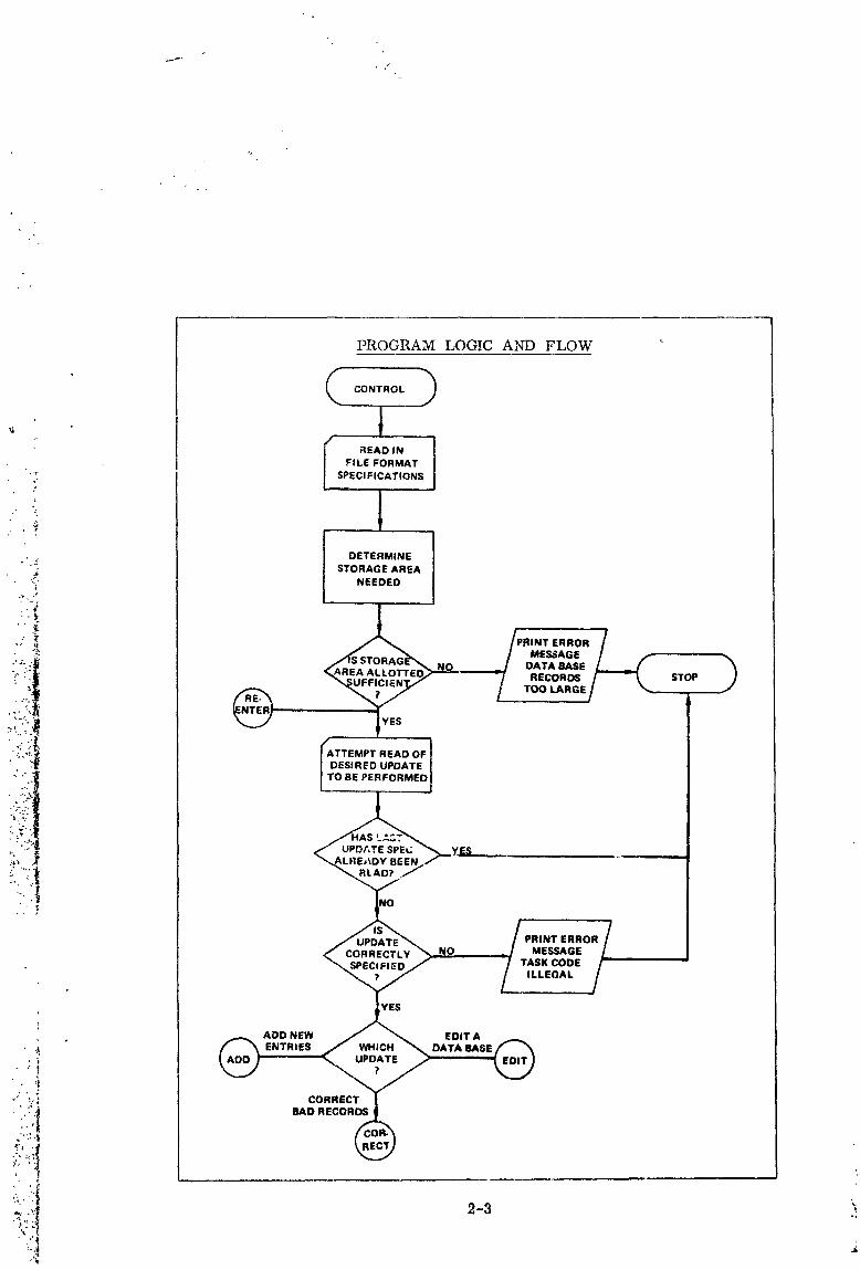
o/.!-., P OORAMLOaICANDFLOW,. _ ";,_;
....t_ ' The program logic and flow should be depicted in a detailed flowchart.,L.. .
.......... The interaction of subroutines, executive routines, etc., should be included.
2-1
: ._._._._1_
1972015507-016

Standard template symbols (see Appendix) should be observed to indicate:
• Type of operation to be performed
• Initial conditions
" • Program modifications.;
t
_ • Explanatoryirform_on
:_ • Connectionlinks
:_:.: This flowchart should develop in detail the contents of each major operation
_• symbol, i. _., arithmetic storing, comparing, branching. Each ,symbol and itscontents must give the necessary information so that the program may be written
_._*' directly from this flowchart.
An example of a detailed flowchart is shown on page 2-3.
_,
2.3 TECHNICAL DESCRIPTION
_-" The technical description should present all program details, techniques,
etc. The technical description should include each program's purpose and func-
- tion within the system; the type of inputs and outputs; examples of the calcula-tions performed; special program considerations, especially in relation to otherprograms; and a glossary of terms unique in meaning to this program.
_' 2.4 INPUT
All input should be described in detail, whether card, tape or other, to-gether with a sample of the input type and a description of the input structure.Fields may be described on layout forms. The type, source, composition, ,"limits, and volume should be specified. Sample input should be included in theappendix. A sample card input description follows on page 2-4.
C"
2.5 INTERNAL DATA ARRAYS DESCRII)TION
- ,o
_ A llstofdataarrays shouldbe given,includingtheirfunctionalname;
, description; the name by which they axe referenced; their location relative to ,"
theprogram, subroutiro,or common area and positionwitharray or word in ,,_i
2-9 _
1972015507-017
PROGRAM LOGIC AND FLOW
,= CONTROLI
I READ IN ]
• FILE FORMAT
"_'; SPECI FICATIONS
.", DETERMINE, - STORAGE AREA
'_ NEEDED
'-_: _ , .
.:" -_ /PRINT ERROR /
_'_: _S STCRAG_ / MESSAGE / ,_
i _ NO _/ DATAeASEL.--.J
.:_.!. _AREAALLOrrED; -/ RECO._/ - I, STOP
"22:2"4 /DESIREDU_'DATEIITO"'RFORMED]
i/-:_"" No yes(°":':"I
/,,,,,.,,.,7CORRECTLY _ MESSAGe /__
"_ SPECIFIED / / TASK CODE /
L_ILLEGAL/- _
ADD NEW / _ EDIT A __
•'"i:i!!',,_ CORRECT_I
ii' BAD RECOR
l
1972015507-018

j-
INPUT
1. INPUT CARDS
The data base format and order of tasks to be performed are inputon data cards,
" ; a. Card]
Column Variable Description Name Format- '.
i
"-'..i 1-5 Blocking Tells the program how NL 5-digit,_ : factor many entries to expect integer
_ _ in each section of the right-_ data base. justified
_ _ 6-10 Entry Tells the program how LR 5-digit" _',!:4 length long each entry in the integer,-, ,: :._.
in char- data base is, allowing right-. "t " _4
..: ',"] acters the program to set up justified-.: ..__, an array into which en-
tries can be read.
1 Update Used as a flag to determine which 1-digitchoice update task the user wants to integer
carry out. 1 means edit, 2 cor-_ rect bad records, 3 add new_ entries.
2. DECK STRUCTURE
a. JOB f. Data Card 1
_' b. FTN g. Data Card 2 .c. _ource deck : repeat g as often asd° LOAD desirede. RUN
.; h. EOF
2-4
1972015507-019

j-
3. EXAMPLE
fbbb 20bb100
a. 20 logical records/blockb. Logical record length= 100 words
-'- e. Perform an edit; new entries tomaser fiie.
3
-?,
.' '_ which they are stored; and the type of information stored in them° Data arrays
._: used for more than one type of information or variable should be so indicated.
- _ Also, equivalence of arrays or parts of arrays should be noted. A sample de-./': ;_ scription follows on page 2-6.
_ 2.6 OUTPUT
-_-."" _ All output should be described in detail, together with a sample of the," :' :"A; output produced. Fields may be described on card layout; layout forms should
.._i'.".?,_ be printed. The type, source, composition, limits, and volume should be spec-
ii!:ii!i!...,, ified.descriptionThesamplefollowsoutpUtonpageSh°uld2-7,be included in the Appendix. A sample output
:! "::: "-..:'_. 2.7 CONTROLS AND CONSTRAINTS
-""_!:".''_-_v In a large program or system of programs, failure of the machine, soft-¢ ware, or particular subprogram may not _._ecessitate a complete re-running of_ the program. The control points at which a program can be restarted should be: discussed in detail. Any changes in the input and output created by a restart at
: a particular control point should also be indicated. 'Fae buil_-in program op-tions should be discussed, and their effect on the restart procedure should be
noted.
The program constraints should also be discussed here. Any limitationson the type of input, output, or problem the program is designed to solve shouldbe indicated.
2-5
1972015507-020

INTERNAL DATA ARRAYS DESCRIPTION
LENGTHVARIABLE DESCRIPTION NAME LOCATIONDECIMAL
Input area This array is used to IN 2000 COMMON/AR/+0store a section of entriesextracted from a data
: base,
: Edit This array is used to ex- 1REQ 300 COMMON/8/+0.,, Masks tract fields from data
7 base entries and compare_ them to the correct
::_. values specified for the? fields.
'_; Correction This array is used to ICORR 290 COMMON/8/+10
_ store images er-_cards the of
_: roneous entries and the
"_i corrections to be made_:: to them.
_ Edit This array is used to IERR 200 COMMON/OAR/+10. values or store the input cards that
bad give the correct values•, entries for fields of entries in
the data base, and then to_: store bad entries dis-
_" covered in the data base,
NOTES: 1. ICORR (2) through ICORR (290) locations are equivalenced toH_EQ (11) through IREQ (300) locations.
2. IERR is used by EDIT as an input area for record form specifi-cations which are converted to masks and stored IREQ, leaving
IERR free as an output area for erroneous records.
i
:,_
:tJ"t
'_ 2-6
1972015507-021
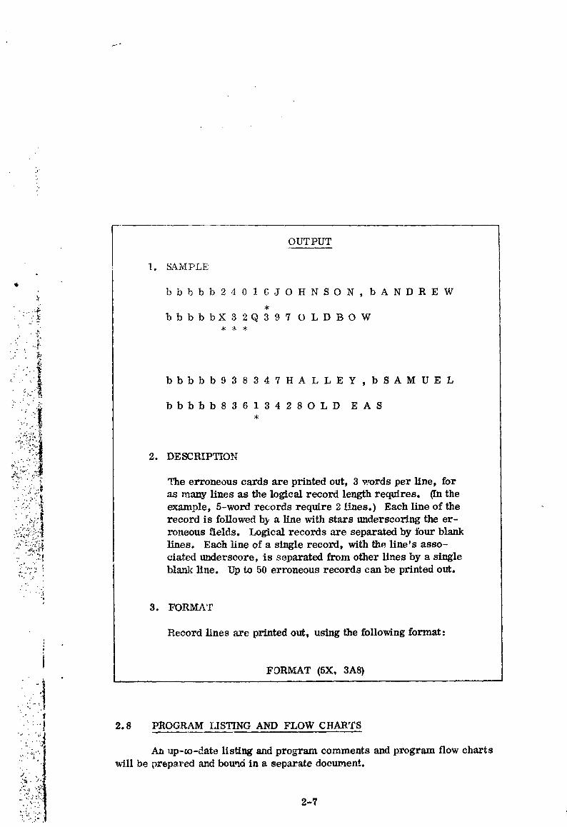
OUTPUT
1. SAMPLE
bbbbb 24016JOHNSON, bANDREW
:" ..... _ bbbbbX32Q397 OLDBOW•/ T
:"""_' bbbbb 83613428 O L D E A S
• " 2_*
."..<::.i The erroneous cards are printedout,3 words per line,for:..-,'<.'_ as many lines as the logical record length re_res. (In the_..--- _ example, 5-word records require 2 lines,) Each line of the
reoo .oe er-roneousfields, Logical records -are separated by four blank
;::"'_5,?{'i lines. Each lineof a singlerecord,withtheline'sasso-,.. '_:'.._._ ciated underscore, is separated from other lines by a single• °_ ";
-:':""_ blankllne. Up to 50 erroneousrecords can be printedout.
• . L."
• ,.]
' 3. FORMAT
Record lines are printed out, using the following format:
i FDRMAT (5X, 3A8)
_'•'" 2.8 PROGRAM LISTING AND FLOW CHARTS
....:_.:;... An up-m-date listing and program comments and progranl flow chartswill be prepared and bound in a separate document.
'_t.}i<.... 2-7
'' ..:
]9720]5507-022
/
SECTION 3
OPERATION DESCRIPTION
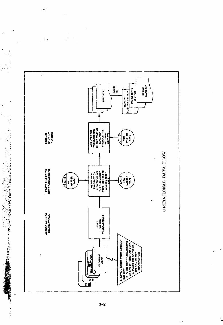
3.1 OPERATIONAL DATA FLOW
The operational data flow should be depicted in a flowchart geared for_. machine operation. The flowchart has a multiple purpose:
•"4 • It defines the input and output.
_: • It establis]_o_s the timing for a sample run, to assist in scheduling
• il and program testing./ ? . '!_
,.* • It provides a brief synopsis of the program functions.
• • It lists the minimum configuration on which the program can be run.
';:._ A sample flowchart follows.
o,_, 3.2 MACHINE SET-UP
,_:_?_ The machine set-up description should provide the operator with a check:_', list of all required inputs and outputs. It shall specify the printer forms; car-
":_::_ tinge tape; format and sequence of input cards; and the complete set-up of all---:, console switches as a function of the computer and the complexity of its oper-
• . 4
...... _g environment. A example set-up summary Is illus_ated on page 3-3.
3.3 INPUT SET-UP
A list of sequenced set-up instructions should follow the machine set-upsummary. Any limits on the system configuration (i. e., SYSTEM TAPE isalways assumed to be on channel I, unit (9) should be specified. An examplefollows on page 3-4.
," 't,
• j'.'
:'"" 3.4 OPERATOR INSTRUCTIONS
"'[;? The operator must be apprised of all messages, halts, and end-of-Job:::_[:....,,, conditions which occur in the normal operation of the machine; he can thereby
;,;, 3-1
1972015507-023
f
: 3-2
1972015507-024


:- .-._,
YN_ SET-UP
1. Check for special instructions contained on backof run card.
2. Mount Deposit Accotmting M_ter File (most cur-
rent date) on channel 5, unit 1.
3,. t:_lace 3-ply stock paper in the printer,
-_ _ 4. Request the program from the 3200 dispatch deck.
._-
• ._ 5. Place program deck in the card reader, followed: by the input parameter cards.
• : 6. Place blank cards in the card punch.
:_ rapidly recognize any abnormal conditions which exist and can take the re-q red action with a minimum of _ste time.
:.. ::_ The operating sequence instructions must be specified, in order of per-_-: formance. A sample Js sho_ below.
"._ OPERATOR INSTRUCTIONS7"
• s Initiate operation:
_.: a) Press AUTOLOAD key to load the system.
-. _, b) System _ll reque_ data; respond and press• _: the "FINISH" key, The system will then be
in operation.
,. Take-Down Procedure:'t
a) R_move the lls_g from the printer,
b) Remove the cards from card punch._i c) Remove and save the type out and parameter
" ' " cards.
_ d) Remove the master file from Servo on chan-, nel 5, trek I,
._?
" 3-4
] 972015507-026

: + ° : . •
+f
.o.
+
•+ ..
3.5 DISPOSITION OF OUTPUT
Normally all ouLput is sent to the dispatcher's desk. In the event thatmulUple copies of output are produced and are to be delivered to specific areas,e.g., Quality Control, Data Inspector, etc., addresses should be designated.
_- 3.6 RESTART P_(OCED[rRE•-_"
_-" The operator must be informed of the sequence of steps to take, in the4
._ event of a machine, soft_,_re, or program failure. He should be aware of any_ control points within the p_ogram from _,hich he can restart the run. He also
." _,
_ should be apprised of any output tha_ can be salvaged.
"_ 3.7 PROGR._nM FAULT IDENTIFICATION
i_ The operator must be apprised of all messages, halts, aud end-of-job
;_Z: conditions which occur in _he normal operation of the machine; he can therebyrapidly recognize any abnormal conditions which exist and can take the requiredaction with a minimum of wasted time.
3.7.1 Programmable Halts
If the programmed halt is included in the pro___un, it should be carefullydocumented, using a separate page for each halt. A sample follows below.
PROGRAMMED HALTS
.,_ Program No.
Halt Description !
! , Iy _alt No. "A" Register "q"Reglster I "P"Re_ster i
Message: • +(,.,+t+
+'+':'I C=,se. !.Corrective Action: -
i]+._. 8-5 ' _'++
]9720]5507-027

V
% _.,° ,,
• f"
•, . --••. - "..
.7•- -" _. •' " " "' k "'_
• , ,° ,. ., ,• • -,: .
°-' :. _ . . • ., -,.-"
If more than three halts are included as part of a program, a separateindex of halts proves extremely useful to the operator iv trying to locate the haltin the manual. For example:
HaltNo. Caus_____e
0112 Printer l/he-up 40,j_. 211_ Recurring tape error 75_-_ 2234 Tape label error 92
3.7.2 Messages
_. A listing of an messages should be provided for each program. If a mes-
"_ sage is followed by a program halt, the halt number should be referenced in the! message: The cause of the mess_ should be explained, and if a halt occurs
at the same time, the operator ac on should be indicated. Since halts are doc--_-_ umenf_ separately from the messages, the page number of the halt should be
: indicated in the message explanation.
4
3.7.3 Console Alter'aflon/Se_e _l_l_s/Alta_.r Keys (If applicable)
_! The documentation should clearly state the purpose of each consoleswitch, and its effect on an_ section of the program, since it could be turned
'_ ON accide_lly during program operation. I?
;' 3.7.4 Operating Manual Layouts _
The oper _a_flngsection should be provided with layouts of the input cards_ and output forms _o enable rapid location of input./¢tttput errors and to prevent
the use of the incorrect card file or incorrect report form.
: Tape records or memory l_'uuts do not have to be _luded in this s_-
tion since they serve no useful 4mrpose to the operator. However, sample re-,: ports and card forms should be included wherever possible. The last layout in
_ the operating manual is the layout of the carriage tape for the printer, if a sl0e- ..:cial tape is required.
'l
1972015507-028

MACHINE UTILIZATION
_" 4.1 PROGRAM LANGUAGE
• _ The source language(s) in which the program v_.s written should be
I 4.2 OPERATING SYSTEM AND VERSION
The particular machine(s) for which the program was designed and the
version of the operating system under which it must be run must be stated.
4.3 MEMORY AND EQUIPMENT USAGE
The programmer must supply information regarding all peripheralequipment used by the program, i.e., card reader, card punch, tape drives, _printer, disk, etc. He •should also supply a detailed map of areas of core used.
An example of a core usage description follows. +-
Routine Starting EndiDg Length (Decimal) _.Location Location
•PROGRAM MAIN 77044 77777 733 :
SUBROUTINE EXEC 75620 76043 223 _•SUBROUTINE AQVW 73500 75617 211"/
COMMON/DATA/ 76044 77043 • 777 ._COMMON/2/ 16000 16273 273System Routines 00000 15777 15777
• Total 19900
4.4 PROGRAM RUN TIME
A summary of ap.l_oximate computer timing should be provided by theprogrammer. The computer time should be broken ,.iowa into compilation andrun time. The run time, ff variable, should be estimated on the basis-of sam- ._
ple runs. Estimates of operator run time should also be stated. Operator runtime may be broken down into input set-up, execution, and takedown times. _*
• . _
• 4-1
1972015507-029
.o
SECTION 5
PROGRAM VALIDATION
5.1 STATEMENT OF METHOD
Since the program may be used by different people, some indication
: should be provided as to what extent the program has been checked out. There-•"" '._ fore, a complete description of the validation procedures used should be included.
: : ,- ,:" Examples of the data used in the validation of the program (i. e., the type and• - ;" series numbers of the data tapes that were used) and the corresponding results
:- , ::: should be provided to aid the user,in verifying the accuracy of the program. Any
•_ _' h_eure modification to the program should be tested, using the input data pro-
.; :::.:.::_ vialed in the example. These test results should then be compared with the pre-:, _ vious test results.
•_,'_!__ It is often not possible for the programmer to check out all the combina-:.:, .:_:_:"_ tions of conditions that might occur in the execution of a program. However,,_---: * the greater the number of conditions illustrated by a sample, the more valuablev,,,.:_:_.:.•., it becomes.
:::%/:, In summary, the purpose of the vaI_dation section is to describe exactly"/:,:'i/ what occurred during the running of the program and the way in which the pro-
-:'7_;" gram goals were accomplished.
'":_.:.:'-"'_ :_. 5,2 DATA SET FOR INPUT AND DESCRIPTION
?/!:()•" The programmer must give an example(s) and describe the _et(s) of in-
_ put data used in debugging the program. Where it is practical, a brief descrip-tion shL,uld accompany the data set, indicating the portion(s) of the programtested by the input data set, The data set selected for inclusion should be cave-fully designed to test the program as comprehensively as possible. It may benecessary to include a series of data sets to fully accomplish the validation ex-
_: " ercise. This is particularly important, since future program modifications will.: :._ _,_ be validated by testing the program with the examples provided in the program_-_-_"' doc_tmentation. Card layout f_rms may be used to describe fields of the input
,:_:i. _:.:| data. The manner in which the data was input should also be specified. Anypertmer_ program,?=:.,:_:,,_ information that is beneficial and to the testing should be in-,
_:_!._ cluded in this section of the program documentation. It should be tmdorstood_:_,•_:_-•_, that the content and depth of the discussion will naturally depend upon the com-
_,_l plexity of the program being documented. In the event that the validation is
9720] 5507-030

obvious or does not apply, this section of the documentation will contain a
statement indicating that it is not applicable.
5.3 PROGRA/VI OUTPIYr AND DESCRIPTION •
The output of the sample ,-an should be included here. The method in
which it was output should be described; the output should also be interpreted.Criteria establishing that the output is valid should be stated.
5-2
1972015507-031
if
SECTION 6
APPENDL-X
Any items in program documentation which require extensiv_ _.*.-_pecial"• discussion in regard to purpose or use, i.e., mathematical co-cepts or items
not within the specific categories delineated in this style manual, will be handledseparately in appendix form.
: A program description paralleling that of Section 2 of specialized sub-, routines called by the program and of any support programs should a/so be iD-i: cluded in the appendices. If the programs or subroutines have been documented
elsewhere, a brief description of their ftmctions and references to the documen-
"_ tation should be given instead, Input and output samples, as mentioned in Section,_ 2, may also be included in appendix form.
• ;_
A glossary of all names (variable, subprogram, and label n&mes) used:_ in the flowcharts and program should also appear in the appendix.
t A list of pertinent reference material should be provided.
._
.:
:' ,._f_
6-1
1972015507-032
•_. APPENDIX
_ The standard IBM template symbols for flowcharting use are shown on
' ': page A-2.
,t 1 ,
', "A
°_
i" t ,_
1972015507-033

/. r


