43
M.R. Ibarra Institute of Nanosciencie of Aragón Laboratory of Advanced Microscopies Condensed Matter Physics Department

M.R. Ibarra
Institute of Nanosciencie of AragónLaboratory of Advanced MicroscopiesCondensed Matter Physics Department


Outline
• The concept of spin currrents• The thermoelectric conversion• Introduction to Thermospin effects• SSE effects in [Fe3O4/Pt]n multilayers• Spin Peltier effect in [Fe3O4/Pt]n multilayers• Thermoelectric power: thermopiles• Conclusions

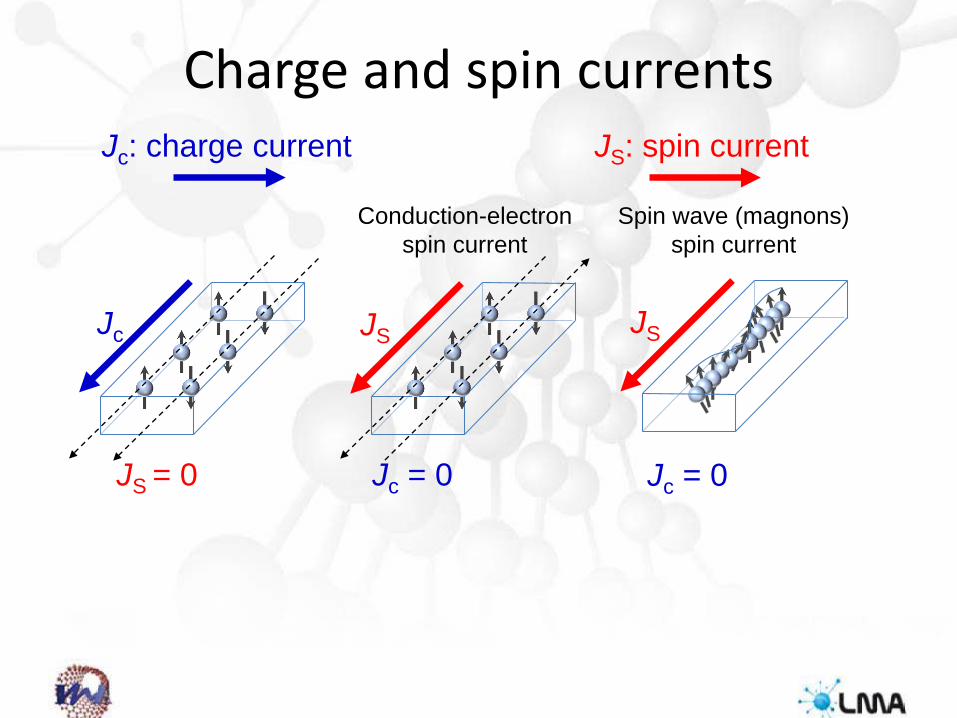
Charge and spin currents
JS = 0
Jc
Jc = 0
JS JS
Jc = 0
Jc: charge current JS: spin current
Conduction-electronspin current
Spin wave (magnons)spin current


Pure Spin Currents
Net electron spin flow
Non-magneticMetal
MagneticInsulator
Magnon flow

Spin Hall effect (SHE)Interconversion of charge – spin currents in materials with high spin orbit coupling (high Z)(Dyakanov & Parel 1971,Hirch 1999)
(Js) Spin (Jc) Charge
Jc
JS
US-L US-L
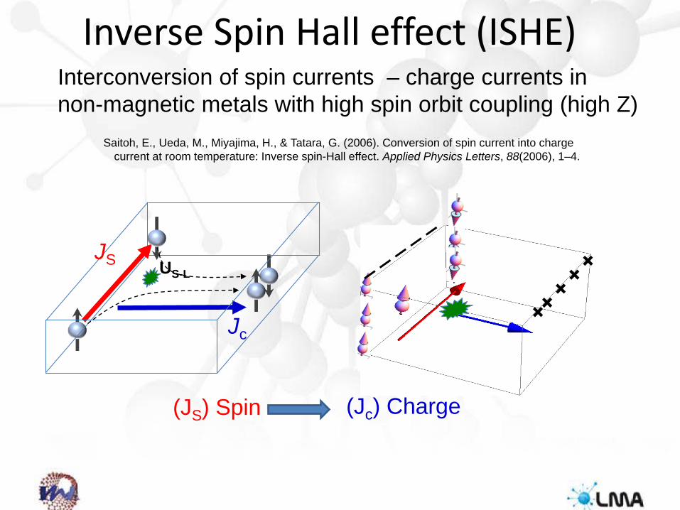
Inverse Spin Hall effect (ISHE)Interconversion of spin currents – charge currents in non-magnetic metals with high spin orbit coupling (high Z)
(JS) Spin (Jc) Charge
Jc
JS US-L
Saitoh, E., Ueda, M., Miyajima, H., & Tatara, G. (2006). Conversion of spin current into charge current at room temperature: Inverse spin-Hall effect. Applied Physics Letters, 88(2006), 1–4.

Thermoelectric effects
Seebeck effect: 𝑆𝑆 = 𝐸𝐸𝛻𝛻𝛻𝛻
𝜵𝜵𝜵𝜵
𝑬𝑬𝐽𝐽 = 𝜎𝜎(𝐸𝐸 − 𝑆𝑆 𝛻𝛻𝛻𝛻) = 0
Peltier effect: Π = 𝑆𝑆 𝛻𝛻
𝜵𝜵𝜵𝜵
+
Thermoelectric power generation Thermoelectric cooling
𝑍𝑍𝛻𝛻 =𝑆𝑆2𝜎𝜎𝜅𝜅
𝛻𝛻
𝜅𝜅 = 𝜅𝜅𝑒𝑒 + 𝜅𝜅𝑙𝑙 𝜅𝜅𝑒𝑒 = 𝐿𝐿𝜎𝜎𝛻𝛻
𝐿𝐿 =𝜋𝜋2
3𝑘𝑘𝐵𝐵𝑒𝑒
2
= 2.44 × 10⁻⁸ �𝑊𝑊Ω𝐾𝐾2
Figure of merit
𝜵𝜵𝑽𝑽

Would it be posible thermoelectriceffect due to spin?
𝜵𝜵𝜵𝜵
𝜵𝜵𝜵𝜵
JS
Spin Peltier Effect (SPE)Spin Seebeck Effect (SSE)
JS

Heat vs. Electricity
To get Electricity To get Heat
Charge
Spin
Seebeck effect Peltier effect
Spin Seebeck effect
Uchida 2008
Spin Peltier effectFlipse 2014
Daimon 2016
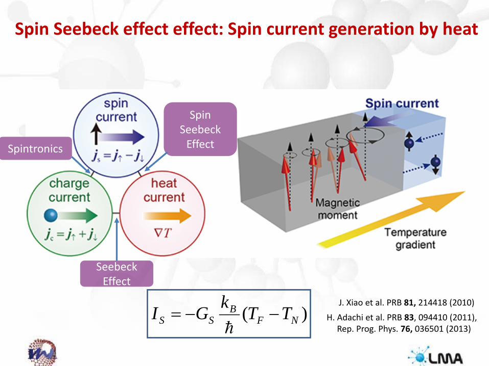
Spin Seebeck effect effect: Spin current generation by heat
)( NFB
SS TTkGI −−=
H. Adachi et al. PRB 83, 094410 (2011), Rep. Prog. Phys. 76, 036501 (2013)
J. Xiao et al. PRB 81, 214418 (2010)
Spintronics
Spin Seebeck
Effect
SeebeckEffect

16
Longitudinal spin Seebeck effect (LSSE)
Longitudinal SSE setup
paramagnet
ferromagnet
Inverse spin Hall effect:
K. Uchida et al.,Appl. Phys. Lett. 97, 172505 (2010).
EISHE = θSHρ(JS × σ)

Spin Seebeck basic principles
• Spin current proportional to applied thermal gradient
• Injected spin current converted in electric voltage by the inverse spin Hall effect
H. Adachi et al. Phys. Rev. B 83, 094410,& Rep. Prog. Phys. 76, (2013) 036501
𝐸𝐸𝐼𝐼𝐼𝐼𝐼𝐼𝐸𝐸 =𝜃𝜃𝐼𝐼𝐼𝐼𝜌𝜌𝐴𝐴
2𝑒𝑒ℏ
𝐽𝐽𝐼𝐼 × �⃗�𝜎
𝐼𝐼𝐼𝐼 = −𝐺𝐺𝐼𝐼𝑘𝑘𝐵𝐵ℏ
(𝛻𝛻𝐹𝐹 − 𝛻𝛻𝑁𝑁)
J. Xiao et al. Phys. Rev. B 81, 214418

Magnon emission associatedwith spin accumulation at themetal-ferromagnet interface (Takahasi et al ICM 2009)
Spin angular momentumtransfer at the interface:Magnon and elecronspin currentinterconversion(Steven et al. PRB 86 (2012) 214424)
SPIN CURRENT AT THE INTERFACES
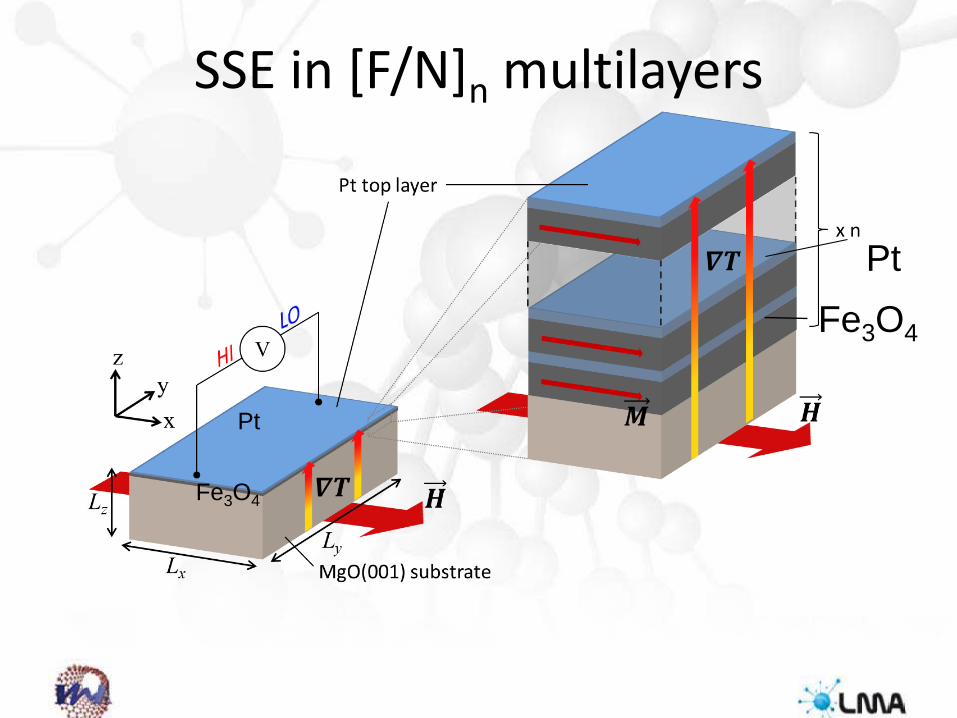
Fe3O4
Pt
Fe3O4
SSE in [F/N]n multilayers
Pt

Combined PLD & Sputtering
KrF Laser (λ = 248 nm)
PLD-sputtering (Neocera Llc) P180-sys
(Neocera Llc)
Sputtering module
21
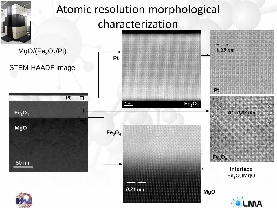
Atomic resolution morphological characterization
MgO/(Fe3O4/Pt)
STEM-HAADF image
0,21 nm MgO
Fe3O4
Interface Fe3O4/MgO
0,39 nm
Pt
a~ 0,83 nm
Fe3O4
Pt
Fe3O4
50 nm
MgO
Fe3O4
Pt
FIB-Pt-C

23Atomic resolution chemical mapping of the interfaces

SSE vs number of Fe3O4/Pt bilayers
-8 -6 -4 -2 0 2 4 6 8-10
-5
0
5
10
V ML /
∆T
(µV/
K)
H (kOe)
n = 1 n = 2 n = 3 n = 6
T = 300 K
n = 1
n = 6
SSE voltage enhancement with incresing number of Fe3O4/Ptbilayers
50 nmMgO
Fe3O4
Pt
50 nm
Ramos et al. Phys. Rev. B 92, 220407(Rap. Comm.) (2015)

-6 -4 -2 0 2 4 6
-0.5
0.0
0.5
1 x Pt/Fe3O4(tF), 300K
tF = 40 nm
(Vy/∆
T) (L
z/Ly)
(µV
/K)
H (kOe)
tF = 160 nm
tFPt
Fe3O4MgO
-6 -4 -2 0 2 4 6
-0.5
0.0
0.5 n = 4
H (kOe)
(Vy/∆
T)(L
z/Ly)
(µV/
K)
n = 1
n x Pt/Fe3O4(40), T=300 K
PtFe3O4
MgO
4 x
Fe3O4
Pt (15 nm)t (nm)
2mm
7mm
SSE dependence on Fe3O4 thickness
A. Anadón et al. 2016) APL (2016)
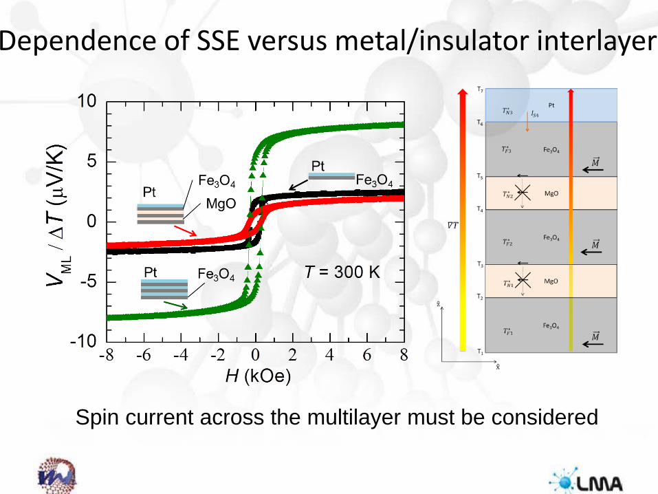
Dependence of SSE versus metal/insulator interlayer
Spin current across the multilayer must be considered

-8 -6 -4 -2 0 2 4 6 8-30
-20
-10
0
10
20
30
V ML /
∆T
(µV/
K)
H (kOe)
n x Fe3O4/Pt(tN) n = 1 n = 6
GSSE
T = 300 K
Pt 15 nm
Pt 7 nm

Optimized configuration
-8 -6 -4 -2 0 2 4 6 8
-30
-20
-10
0
10
20
30 n = 12n = 6
V ML/∆
T (µ
V/K)
H (kOe)
T = 300 K
n = 1
[Fe3O4(23)/Pt(7)]n
Largest SSE voltage measured in a thin film based structure!!
VML ≈ 28 µV/ K !!

29
Mechanism of LSSE enhancement in multilayer systems
Essence of LSSE enhancement: Boundary conditions for spin currents flowing normal to P/F interfaces
(i) spin currents must disappear at the top and bottom surfaces(ii) spin currents are continuous at the interfaces
Spin
cur
rent
PtFe3O4 Fe3O4
T = 300 K
z
PtFe3O4
Magnon spin current
Electron spin current
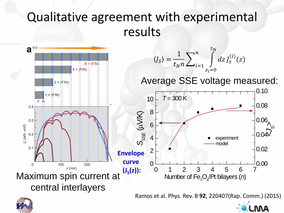
Qualitative agreement with experimental results
0 1 2 3 4 5 6 70
2
4
6
8
10
experiment
T = 300 K
S SSE (µV
/K)
Number of Fe3O4/Pt bilayers (n)
0.00
0.02
0.04
0.06
0.08
0.10
model
<JS>
Average SSE voltage measured:
𝐽𝐽𝐼𝐼 =1𝑡𝑡𝑁𝑁𝑛𝑛
�𝑖𝑖=1
𝑛𝑛�
𝑧𝑧𝑖𝑖=0
𝑡𝑡𝑁𝑁
𝑑𝑑𝑑𝑑 𝐽𝐽𝑠𝑠(𝑖𝑖)(𝑑𝑑)
Maximum spin current at central interlayers
Envelope curve(JS(z)):
Ramos et al. Phys. Rev. B 92, 220407(Rap. Comm.) (2015)

(Ilustration from Graham Jones)
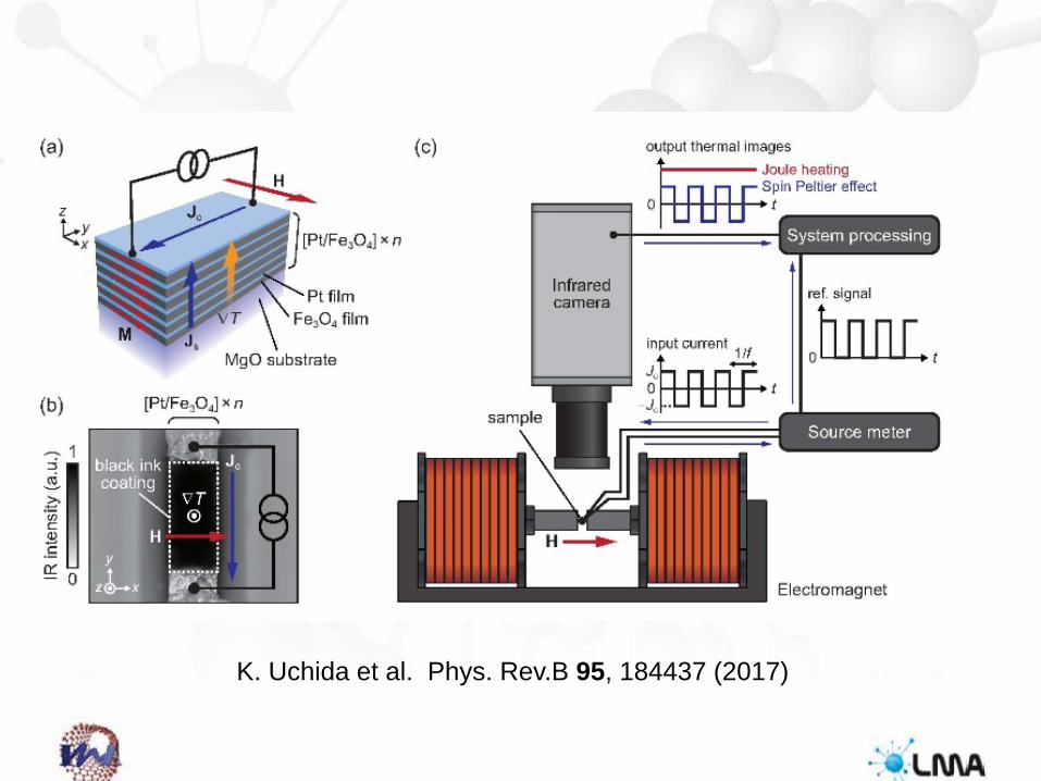
K. Uchida et al. Phys. Rev.B 95, 184437 (2017)

Spin peltier effect
K. Uchida et al. Phys. Rev.B 95, 184437 (2017)

Strong enhancement of the spin peltier effect in multiple bilayers
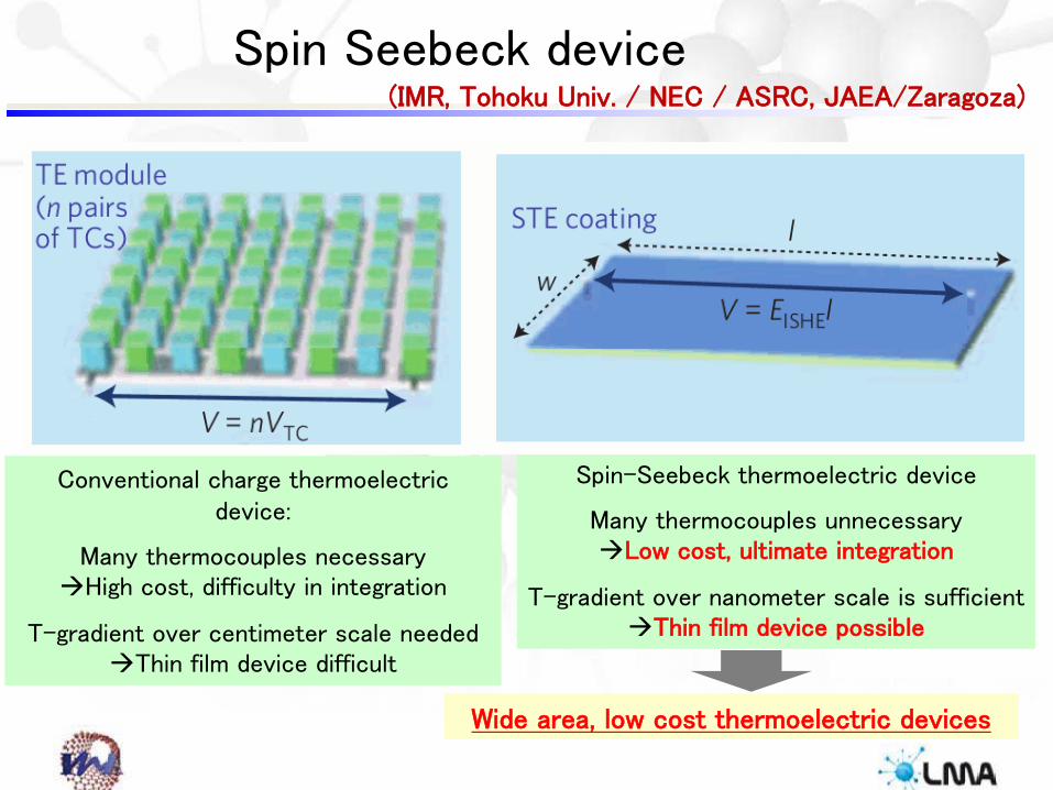
Spin Seebeck device
Wide area, low cost thermoelectric devices
Conventional charge thermoelectric device:
Many thermocouples necessaryHigh cost, difficulty in integration
T-gradient over centimeter scale neededThin film device difficult
Spin-Seebeck thermoelectric device
Many thermocouples unnecessaryLow cost, ultimate integration
T-gradient over nanometer scale is sufficientThin film device possible
(IMR, Tohoku Univ. / NEC / ASRC, JAEA/Zaragoza)
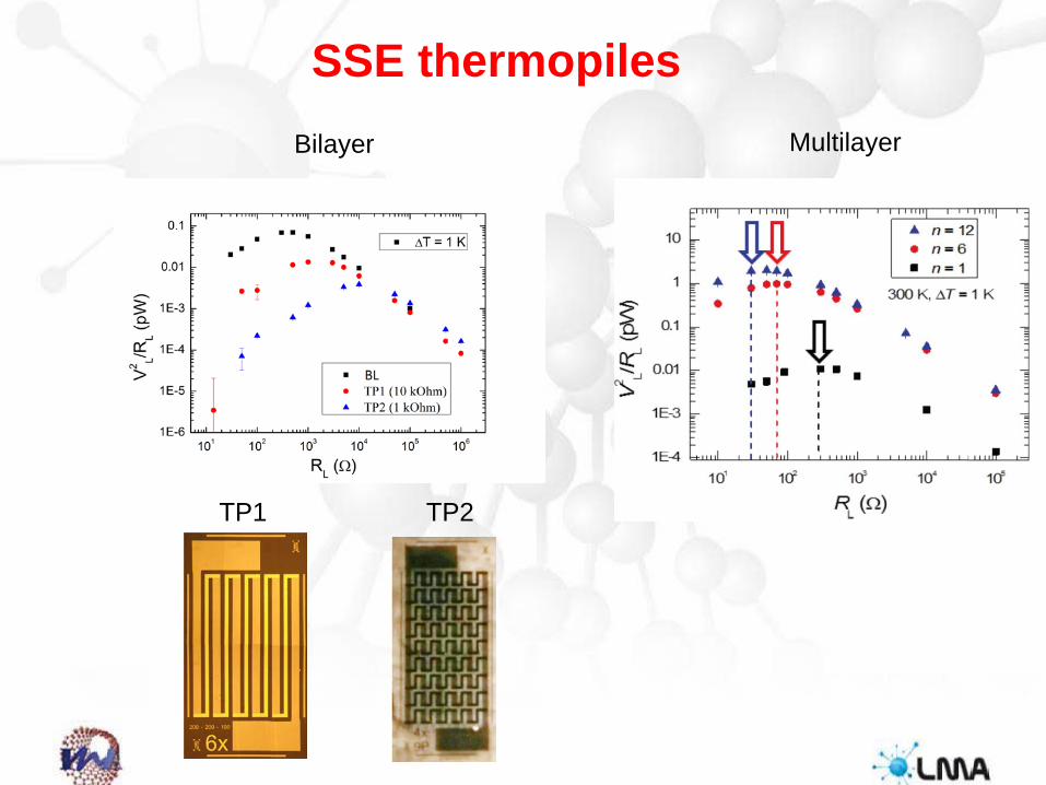
SSE thermopilesBilayer Multilayer
TP2TP1

Spin current conversión at the interfaces F/N gives rise to anstrong enhancement of the thermospin effects in multiplebilayers and constitutes an excellent play ground for thestudy of new physical phenomena and promising for devicesapplication
K. Uchida et al. review Proceedings of the IEEE 104, 1499 (2016)
LSSE Termopower LSSE power factor

Monographic issue in Journal PhysD: Applied Physics on
CALORITRONICS to appear soon
Enhanced thermo-spin effects in iron-oxide/metal multilayers
R Ramos1, I. Lucas2,3,4, P. A. Algarabel4,5, L. Morellón2,3,4,K. Uchida6,7,8, E. Saitoh1,8,9,10 and M. R. Ibarra2,3,4,11

Development of thin-film thermoelectric SSE baseddevices
Strategic Japanese-Spanish Cooperative Research Program Nanotechnologies and new materials for environmental
challenges


