STABLCOR PRESENTATION STABLCOR PRESENTATION THERMALWORKS THERMALWORKS WHAT IS STABLCOR? STABLCOR is a Laminate technology for: PCBs Substrates Presentation at SCV Chapter, CPMT Society meeting -- December 8, 2004 www.cpmt.org/scv/
Transcript
1
STABLCOR PRESENTATIONSTABLCOR PRESENTATION
THERMALWORKSTHERMALWORKS
WHAT IS STABLCOR?
STABLCOR is a Laminate technology for:
PCBs
Substrates
Presentation at SCV Chapter, CPMT Society meeting -- December 8, 2004www.cpmt.org/scv/
2
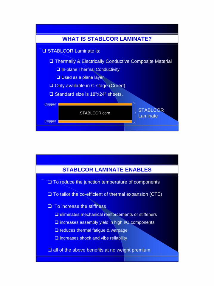
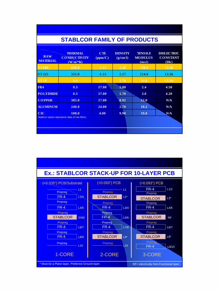
WHAT IS STABLCOR LAMINATE?
STABLCOR Laminate is:
Thermally & Electrically Conductive Composite Material
In-plane Thermal Conductivity
Used as a plane layer
Only available in C-stage (Cured)
Standard size is 18”x24” sheets.
STABLCOR core STABLCOR Laminate
Copper
Copper
STABLCOR LAMINATE ENABLES
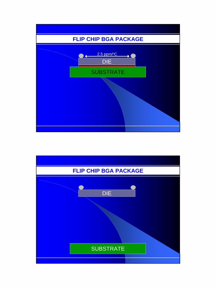
To reduce the junction temperature of components
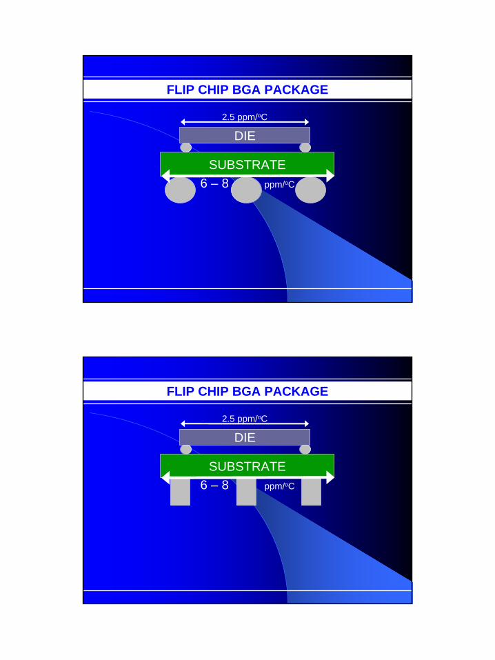
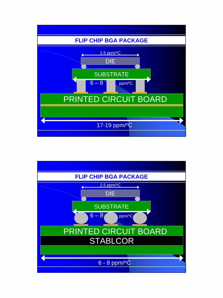
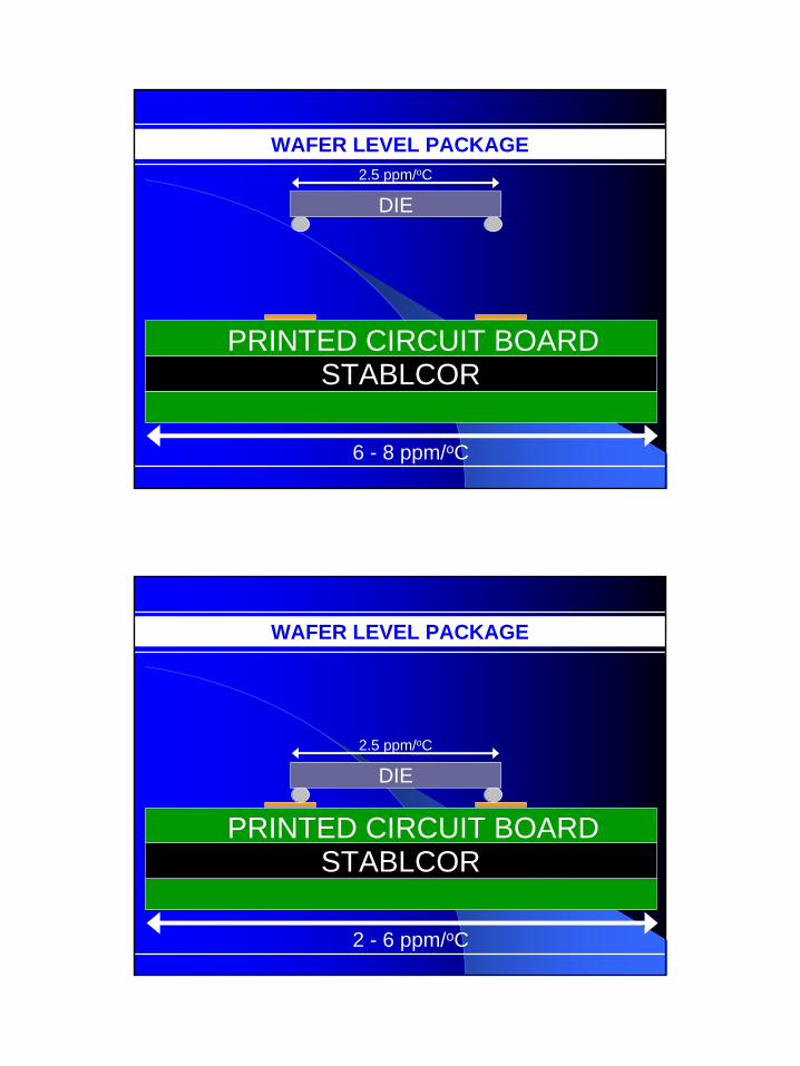
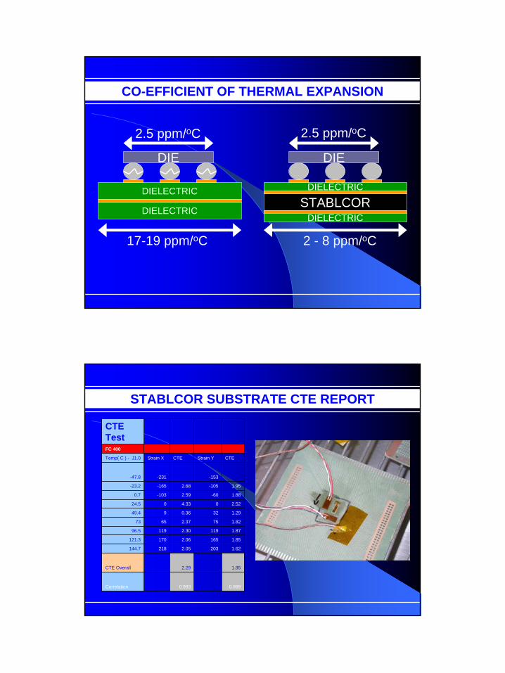
To tailor the co-efficient of thermal expansion (CTE)
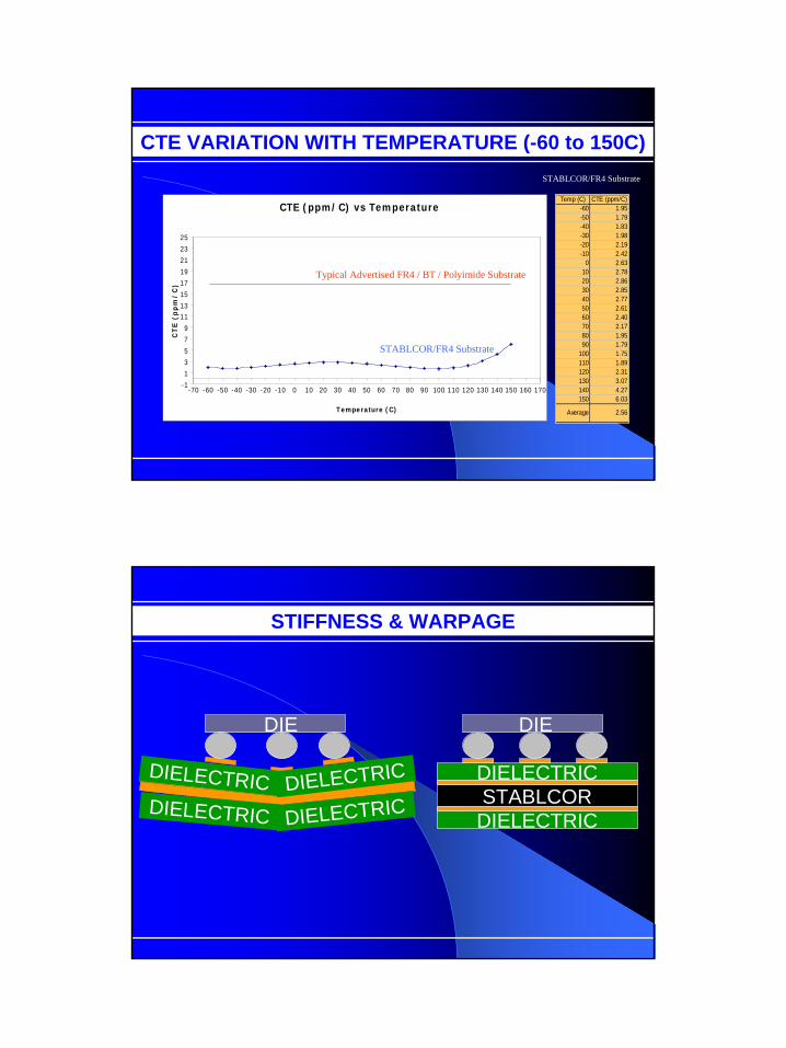
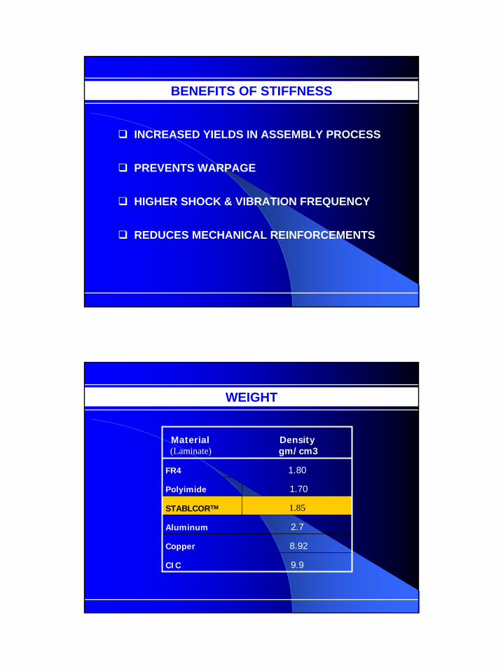
To increase the stiffness
eliminates mechanical reinforcements or stiffeners
increases assembly yield in high I/O components
reduces thermal fatigue & warpage
increases shock and vibe reliability
all of the above benefits at no weight premium
3
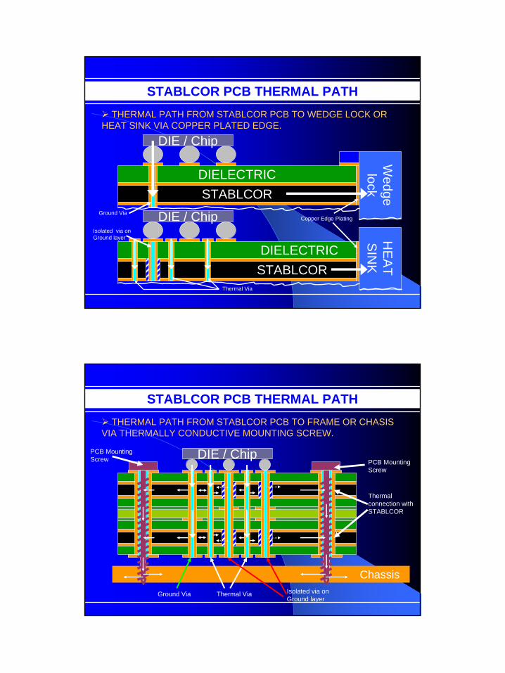
STABLCOR PCB THERMAL PATH
DIELECTRICSTABLCOR
DIE / Chip
Wedgelock
DIELECTRIC STABLCOR
DIE / Chip
HE
AT
SIN
K
Thermal Via
Ground Via
Isolated via on Ground layer
Copper Edge Plating
THERMAL PATH FROM STABLCOR PCB TO WEDGE LOCK OR HEAT SINK VIA COPPER PLATED EDGE.
STABLCOR PCB THERMAL PATHTHERMAL PATH FROM STABLCOR PCB TO FRAME OR CHASIS
VIA THERMALLY CONDUCTIVE MOUNTING SCREW.
Thermal connection with STABLCOR
DIE / Chip
Thermal ViaGround Via Isolated via on Ground layer
Chassis
PCB Mounting Screw
PCB Mounting Screw
4
DIE
/ Chip
Thermal Via
Ground Via
Isolated via on Ground layer
Wedge Lock
Wedge Lock
Ground Pin
Thermal Via
Edge Plating
Edge Plating
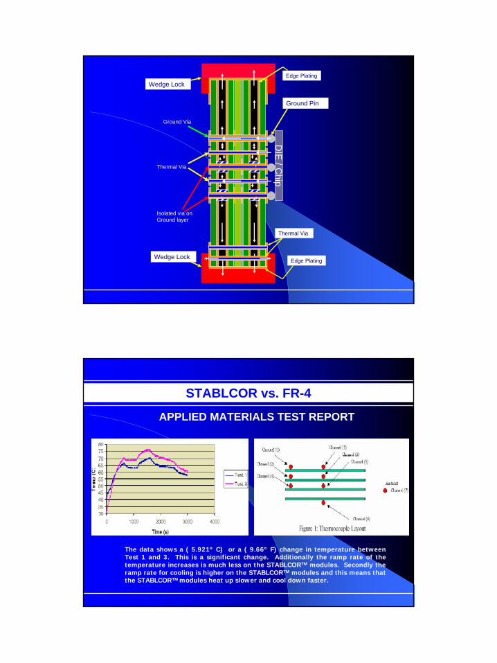
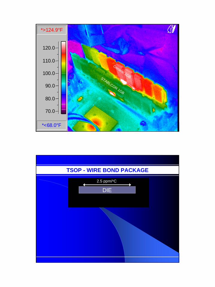
STABLCOR vs. FR-4
The data shows a ( 5.921º C) or a ( 9.66º F) change in temperature between Test 1 and 3. This is a significant change. Additionally the ramp rate of the temperature increases is much less on the STABLCORTM modules. Secondly the ramp rate for cooling is higher on the STABLCORTM modules and this means that the STABLCORTM modules heat up slower and cool down faster.


![Hybrid Threaded Processing for Sparse Data Kernels › wp-content › uploads › 2018 › ... · Profile on an X86 system Overhead Symbol 13.82% [.] svd_ATxb 13.36% [.] svd_ATxb2](https://static.documents.pub/doc/80x56/5f0355147e708231d408b0eb/hybrid-threaded-processing-for-sparse-data-kernels-a-wp-content-a-uploads-a.jpg)


