14
PRESENTATION ON 3 PHASE - INDUCTION MOTOR
| Date post: | 14-Apr-2018 |
| Category: |
Documents |
| Upload: | pushkar-pandit |
| View: | 219 times |
| Download: | 0 times |
7/27/2019 Presentation on 3 Phase Motor
http://slidepdf.com/reader/full/presentation-on-3-phase-motor 1/14
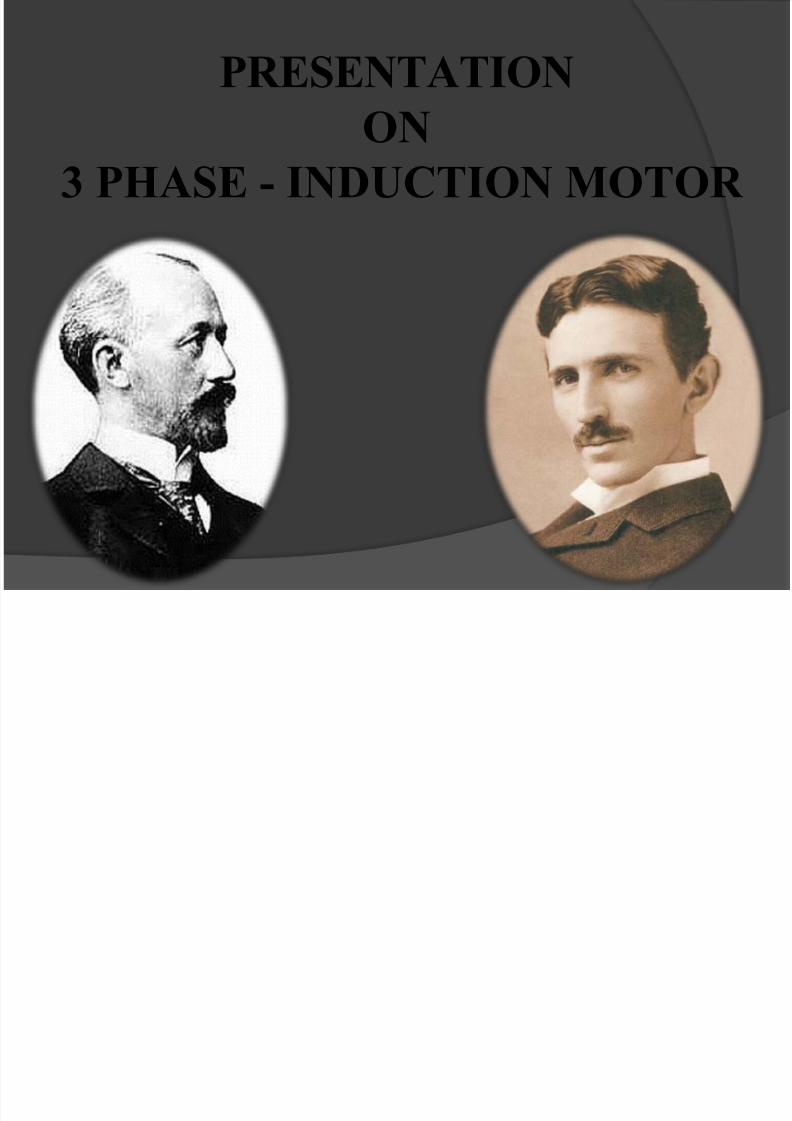
PRESENTATION
ON3 PHASE - INDUCTION MOTOR
7/27/2019 Presentation on 3 Phase Motor
http://slidepdf.com/reader/full/presentation-on-3-phase-motor 2/14
1Introduction
2 History
3 Principle of operation4 Starting of Motor
5 Speed control
6 Types of 3 Phase Induction Motors
7 Construction8 Production of Rotating magnetic Field
Contents

7/27/2019 Presentation on 3 Phase Motor
http://slidepdf.com/reader/full/presentation-on-3-phase-motor 3/14
An induction motor (IM) is a type of
asynchronous AC
motor where power
is supplied to the
rotating device by
means of
electromagneticinduction
Three-phase induction motors
INTRODUCTION
7/27/2019 Presentation on 3 Phase Motor
http://slidepdf.com/reader/full/presentation-on-3-phase-motor 4/14
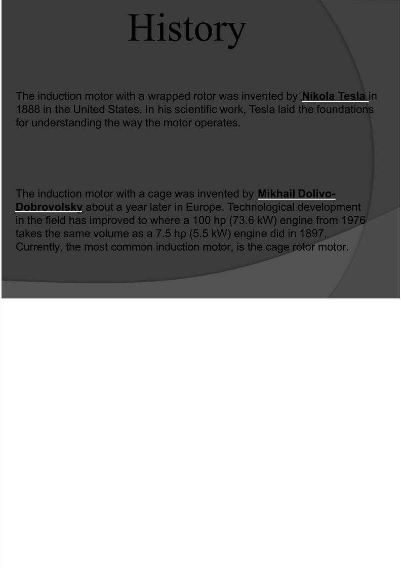
History
The induction motor with a wrapped rotor was invented by Nikola Tesla in
1888 in the United States. In his scientific work, Tesla laid the foundations
for understanding the way the motor operates.
The induction motor with a cage was invented by Mikhail Dolivo-
Dobrovolsky about a year later in Europe. Technological developmentin the field has improved to where a 100 hp (73.6 kW) engine from 1976
takes the same volume as a 7.5 hp (5.5 kW) engine did in 1897.
Currently, the most common induction motor, is the cage rotor motor.
7/27/2019 Presentation on 3 Phase Motor
http://slidepdf.com/reader/full/presentation-on-3-phase-motor 5/14
Principle of operationThe operation of a 3 Phase Induction Motor is based
upon the application of Faraday’s Law ,Len’s Law
and Lorentz force on a conductor when kept in a
magnetic field whose direction can be found by
Fleming’s Left Hand Thumb Rule.
In a 3 Phase Induction motor ,current is supplied onto the
rotor. This then creates a magnetic field which, through
magnetic interaction, links to the rotating magnetic field in
the stator which in turn causes the rotor to turn. The
rotating Magnetic flux induces currents in the windings of
the rotor in a manner similar to currents induced in
A transformer's secondary winding.
7/27/2019 Presentation on 3 Phase Motor
http://slidepdf.com/reader/full/presentation-on-3-phase-motor 6/14
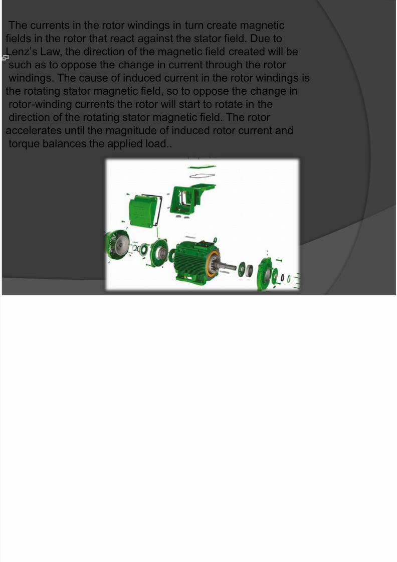
The currents in the rotor windings in turn create magnetic
fields in the rotor that react against the stator field. Due to
Lenz’s Law, the direction of the magnetic field created will be
such as to oppose the change in current through the rotor windings. The cause of induced current in the rotor windings is
the rotating stator magnetic field, so to oppose the change in
rotor-winding currents the rotor will start to rotate in the
direction of the rotating stator magnetic field. The rotor
accelerates until the magnitude of induced rotor current and
torque balances the applied load..
7/27/2019 Presentation on 3 Phase Motor
http://slidepdf.com/reader/full/presentation-on-3-phase-motor 7/14
In a three phase induction motor, the induced emf in the rotor circuit depends
on the slip of the induction motor and the magnitude of the rotor current
depends upon this induced emf (electromotive force). When the motor is
started, the slip is equal to 1 as the rotor speed is zero, so the induced emf inthe rotor is large. As a result, a very high current flows through the rotor. This is
similar to a transformer with the secondary coil short circuited, which causes
the primary coil to draw a high current from the mains. Similarly, when an
induction motor starts, a very high current is drawn by the stator, on the order of
5 to 9 times the full load current. This high current can damage the motor windings and because it causes heavy line voltage drop, other appliances
connected to the same line may be affected by the voltage fluctuation. To avoid
such effects, the starting current should be limited ……
STARTING OF MOTOR
7/27/2019 Presentation on 3 Phase Motor
http://slidepdf.com/reader/full/presentation-on-3-phase-motor 8/14
The rotational speed of the rotor is controlled by the number of pole pairs (number of windings in the stator) and by the frequencyof the supply voltage. Before the development of cheap power electronics, it was difficult to vary the frequency to the motor andtherefore the uses for the induction motor were limited. There are
various techniques to produce a desired speed. The mostcommonly used technique is PWM(Pulse Width Modulation), inwhich a DC signal is switched on and off very rapidly, producing asequence of electrical pulses to the inductor windings
SPEED CONTROL

7/27/2019 Presentation on 3 Phase Motor
http://slidepdf.com/reader/full/presentation-on-3-phase-motor 9/14
TYPES OF 3 PHASE
MOTORS SQUIRREL CAGE MOTOR : Motor consisting of Squirrel
Cage rotor .
SLIP – RING MOTOR : Motor consisting of
slip – ring rotor.
7/27/2019 Presentation on 3 Phase Motor
http://slidepdf.com/reader/full/presentation-on-3-phase-motor 10/14
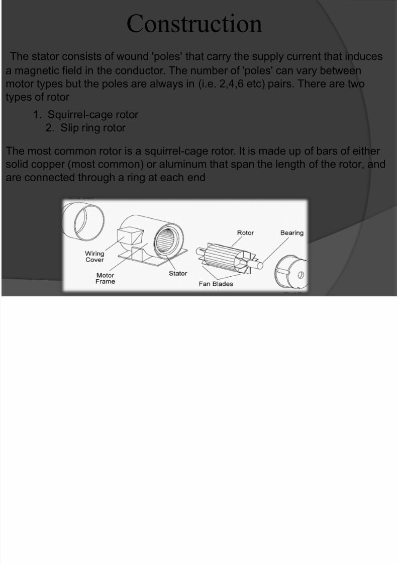
The stator consists of wound 'poles' that carry the supply current that induces
a magnetic field in the conductor. The number of 'poles' can vary betweenmotor types but the poles are always in (i.e. 2,4,6 etc) pairs. There are two
types of rotor
Construction
1. Squirrel-cage rotor
2. Slip ring rotor
The most common rotor is a squirrel-cage rotor. It is made up of bars of either
solid copper (most common) or aluminum that span the length of the rotor, and
are connected through a ring at each end
7/27/2019 Presentation on 3 Phase Motor
http://slidepdf.com/reader/full/presentation-on-3-phase-motor 11/14
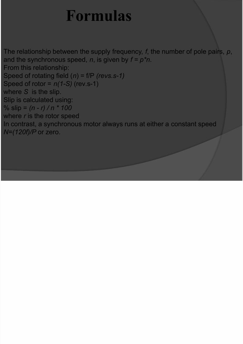
Formulas
The relationship between the supply frequency, f , the number of pole pairs, p,
and the synchronous speed, n, is given by f = p*n.
From this relationship:
Speed of rotating field (n) = f/P (revs.s-1)
Speed of rotor = n(1-S) (rev.s-1)where S is the slip.
Slip is calculated using:
% slip = (n - r) / n * 100
where r is the rotor speed
In contrast, a synchronous motor always runs at either a constant speedN=(120f)/P or zero.
7/27/2019 Presentation on 3 Phase Motor
http://slidepdf.com/reader/full/presentation-on-3-phase-motor 12/14
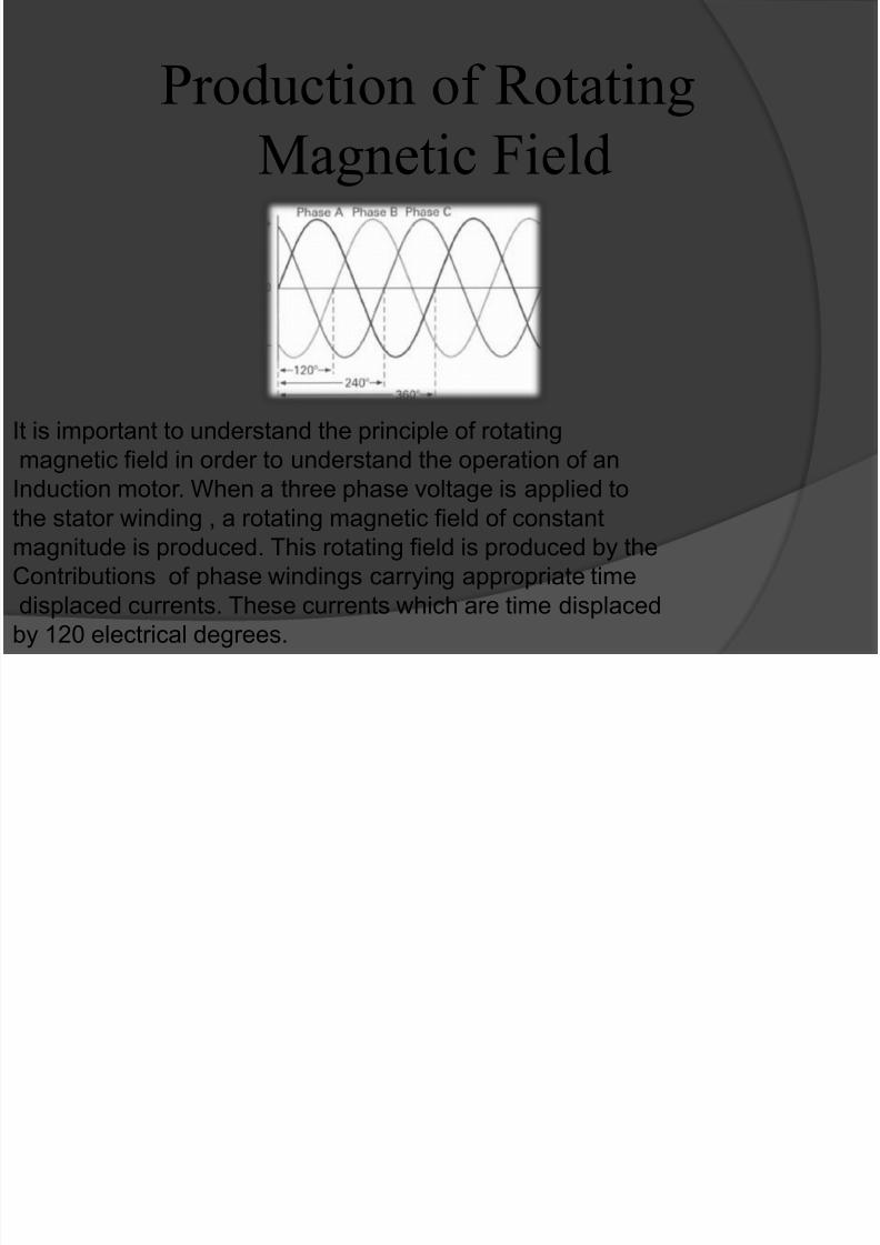
Production of Rotating
Magnetic Field
It is important to understand the principle of rotating
magnetic field in order to understand the operation of anInduction motor. When a three phase voltage is applied to
the stator winding , a rotating magnetic field of constant
magnitude is produced. This rotating field is produced by the
Contributions of phase windings carrying appropriate time
displaced currents. These currents which are time displacedby 120 electrical degrees.
7/27/2019 Presentation on 3 Phase Motor
http://slidepdf.com/reader/full/presentation-on-3-phase-motor 13/14
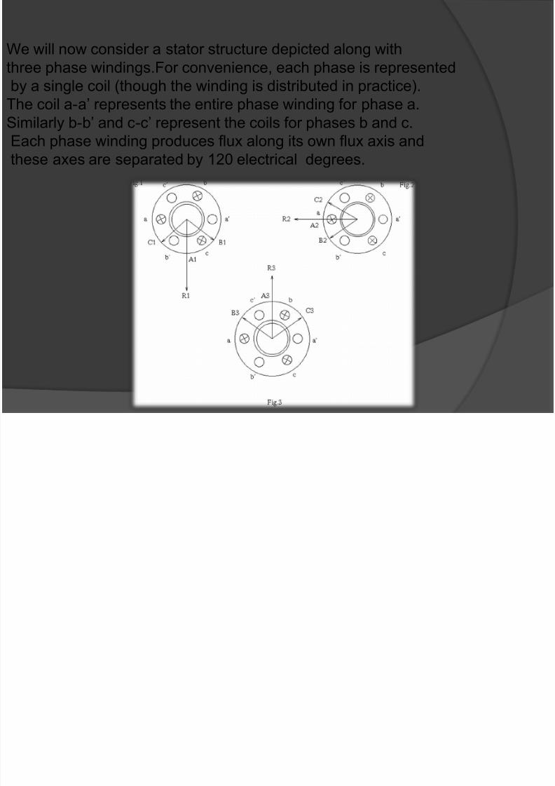
We will now consider a stator structure depicted along with
three phase windings.For convenience, each phase is represented
by a single coil (though the winding is distributed in practice).
The coil a-a’ represents the entire phase winding for phase a.
Similarly b-b’ and c-c’ represent the coils for phases b and c.
Each phase winding produces flux along its own flux axis and
these axes are separated by 120 electrical degrees.
7/27/2019 Presentation on 3 Phase Motor
http://slidepdf.com/reader/full/presentation-on-3-phase-motor 14/14
Thank You
This presentation has been made in an attempt to explain the concept behind an
induction by the group comprising members:
Pushkar A Pandit (Roll No- 46)
Nikki Paliwal (Roll No- 74)
Ashwin Koche (Roll No-29)
Pankaj Sachdev (Roll No-61)
Ayush (Roll No-30)
Arpit Jaiswal(Roll No-28)
Kunal Rewatkar(Roll No-76)


