31
PRESENTATION ON JIGS AND FIXTURES (GROUP G) HND MECHANICAL ENGINEERING I (REGULAR SCHOOL)
| Date post: | 11-Dec-2015 |
| Category: |
Documents |
| Upload: | michael-castro-abudu |
| View: | 243 times |
| Download: | 0 times |

PRESENTATIONON
JIGS AND FIXTURES (GROUP G) HND MECHANICAL ENGINEERING I (REGULAR SCHOOL)

• EGYIR MICHAEL 07098386• EMMANUEL YARTEL 07098374• DANIEL AVISEY TEGAH 07098389• EMMANUEL AGYEI 07098360• GODSON AWUYEH 07098392 • ERIC AMOANI DARKO 07098398• ERIC KOTEY NEEQUAYE 07098365• ISAAC COLEMAN 07098384• ROBERT SOMETIEMAH 07098382• TAWIAH DASSAH 07098377• ASSOAH YAW EVANS 07098416• LOUIS YAWSON 07098351

OBJECTIVEAfter this lesson student should be able to• Understand the principle underlying jigs and fixtures design.• Sketch and explain the six degrees of freedom.• Explain how clamping as a securing device prevents or restrains
body movement.• Define and explain jig and fixture.

INTRODUCTIONThe application of jigs and fixtures is important aspect of workshop engineering, and their application is worthy of some consideration on all bit the simplest types of production, small orders and tool room work.Jigs and fixture are appliances used in manufacture or assembly and to facilitate the operation to which they are applied. The primary object of their use might be facilitate the holding and support of an awkward or frail article for some machining operation. To position a component and to guide the cutters in the operations so that every component produced will be uniform to accommodate several component at one setting to take advantage of multiple machining and to hold a component which Could not be held conveniently without a fixture and so on.
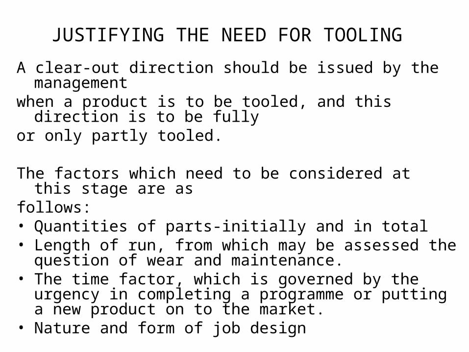
JUSTIFYING THE NEED FOR TOOLING A clear-out direction should be issued by the management when a product is to be tooled, and this direction is to be fully or only partly tooled.
The factors which need to be considered at this stage are as follows:• Quantities of parts-initially and in total• Length of run, from which may be assessed the question of wear
and maintenance.• The time factor, which is governed by the urgency in completing a
programme or putting a new product on to the market. • Nature and form of job design

THE NEED FOR JIGS AND FIXTURES• To ensure that all parts produced are identical in the form and
size.• To produce interchangeable parts at a reduced cost.• To increase accuracy and to reduce manual operations.• To take advantage of employing semi-skilled labour.• To facilitate assembly.• To reduce overall cost.

FUNDAMENTAL OF GOOD JIGS AND FIXTURES DESIGN
• Location : The location portion of the jig or fixtures must be definite, simple, visible and clear. For first operation work on forgings or rough castings, no more than three locating base points should be used . Locations should be adjustable when variations in size of components are likely.
• Clearance : Adequate finger clearance must be allowed to facilitate loading and unloading, and to cater for variable dimensions of castings and forgings. Allowance must be made also for machining burrs.
• Loading and unloading : These elemental operations must be as simple as possible, without being dangerous and causing the operator fatigue.

• Clamping : The clamping of the component must be positive and directed against a solid part of the fixture. The most effective form of clamping should be used, according to the type of fixture, size and form of component and type of operation .If hexagonal nuts are to be used, one size only should be specified to avoid a multiplicity of spanners. Spring placed under clamps save time, and is a boon to the operator.
• Foolproofing and safety : Jigs and fixtures must be designed so that the component can be located only in the required position. The addition of pegs may be necessary in some instances to ensure safety.

• Ejecting Devices : Ejecting devices are essential for heavy and close fitting components. Time is saved and possibility of the tool or component being damaged is eliminated.
• Handling : Heavy jigs and fixtures should be provided with handles, eye bolts, hand slots or other refinements to permit easy and safe handling.

JIGA jig is a device to which a component is fastened so that certain machining operations may be done or carried out. The jig is designed in such a way that one or more cutting tools are guided to the same position on any number of similar component that may be used in a jig.
FIXTUREA fixture is similar to a jig, but the cutting vices are not guided. Briefly the difference between a jig and fixture is that a jig incorporates hardened steel bushes for guiding the tools that are used in machining the component, whereas with a fixture, the tools used for machining the component are worked independently, and are in fact, guide manually by the machine operator.

THE SIX DEGREE OF FREEDOMThe figure below illustrates a body that is suspended in space. The body is said to have Six degree of freedom of movements. (3- lateral,& 3- rotational ) Consider the possible movements of the free body shown,ie with respect to the three mutually perpendicular axes x - x, y - y, z - z.3-TranslationsIt can-• Move along y – y.• Move along x – x.• Move along z – z.
3-Rotations• Rotate about y – y.• Rotate about x – x.• Rotate about z – z.

PRINCIPLE OF LOCATIONIn order to fix, definitely, the position of a body in space, it is necessary to account for the six degree of freedom. The body shown
may move laterally in the directions OX, OY, OZ in addition to which it may rotate about the axes – six possibilities in all. When designing location Facilities, we must keep this in mind so that the arrangement will provide positive restraint as well as ensuring the surface relationship necessitated on the job in hand. There are, in addition , certain natural locational relationships between surfaces, points and lines of which the reader is no doubt aware but their significance to the matter in hand needs to be elaborated.
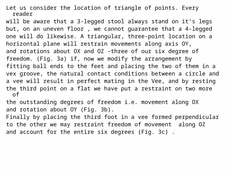
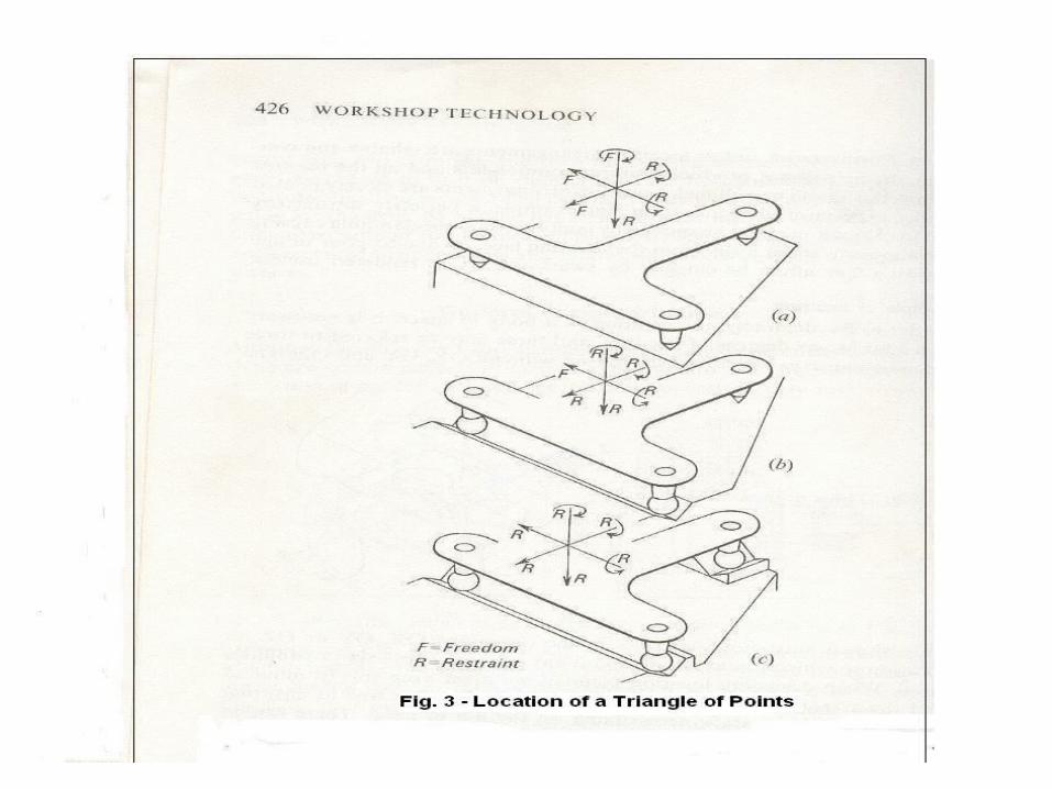
Let us consider the location of triangle of points. Every reader will be aware that a 3-legged stool always stand on it’s legs but, on an uneven floor , we cannot guarantee that a 4-legged one will do likewise. A triangular, three-point location on a horizontal plane will restrain movements along axis OY, and rotations about OX and OZ –three of our six degree of freedom. (Fig. 3a) if, now we modify the arrangement by fitting ball ends to the feet and placing the two of them in a vex groove, the natural contact conditions between a circle and a vee will result in perfect mating in the Vee, and by resting the third point on a flat we have put a restraint on two more of the outstanding degrees of freedom i.e. movement along OX and rotation about OY (Fig. 3b).Finally by placing the third foot in a vee formed perpendicular to the other we may restraint freedom of movement along OZ and account for the entire six degrees (Fig. 3c) .

Now it might be argued that the effort could have beenachieved by dimples or stops on the original flat surface. This
is quite true for one particular component, but we should accommodate itself to variations in size, and if a second component with feet slightly varying in size, or not exactly on the same triangle were fitted to dimples or stops it would not be completely located against every possible degree ofmovement. This case is given merely as an example of principles involved.

TYPES OF LOCATIONThere are different types of location. Some of them are1. Vee location2. Button or peg location3. Fix Block location4. Adjustable location5. Screw locationIn order to locate an object in a definite position all the six degree of freedom must be accounted for. However, six different locators are seldomly used in practice because clamps are usually used to secure the component.

In many types of jigs and fixtures, the contacting point will be small and for this purpose the pieces illustrated at Fig 4. The button locators (a) and (b) are used for the side or endlocation while the remainder are attached to the base of thefixture to sit beneath the component. The button (c) is not recommended for the following reasons. Drilling produce slight burr around the periphery of the hole, and apart with the drill hole, if located over (e) will not lie flat on the locating face. This can be overcome by arranging for all drilled holes to becountersunk, but the most satisfactory step to take is provided such as buttons such as (c) and (d) to seat in counter bored recesses in the fixture base. Not only do drill holes suffer from burrs, but there is always a likely hood that the hole contains dirt and oil which may slip out and become embedded in the force of a jig unless a generous recesses is provided. Fig. 4explains and shows how button or peg location is used.


At Fig. 5a. The support face of the jig is made to the profile to which the component should confirm, and when loading the jig the job is clamp in the most favorable condition. The Support
show at (Fig. 5b) is springloaded so that it may adjust itself to the rough face of the component before being locked up.

CLAMPINGThe Clamp is a device used to secure a component firmly by friction.
Requirements of a clamping device .1. it must hold the work piece against the cutting force without
causing damage to it.2. The clamping pressure should be directed against the solid portion
of the component.3. Clamps which act against finished machined faces should be faced
with strips of copper, brass fibre or similar soft material. Position of the clamp
1. Clamping must be at the thick section of the work piece to avoid distortion due to clamping forces.
2. The clamps must be positioned so that they can be operated easily and safely by the operator.

TYPES OF CLAMPS• Strap clamp.• Universal strap clamp.• Slotted clamp.• Plate clamp.• Screw clamp.• Cam clamp.• Swinging clamp.• Bridge clamp.• Double acting clamp.• Flat clamp.• Pivoted clamp.• Wedge clamp.• Equalising clamp..


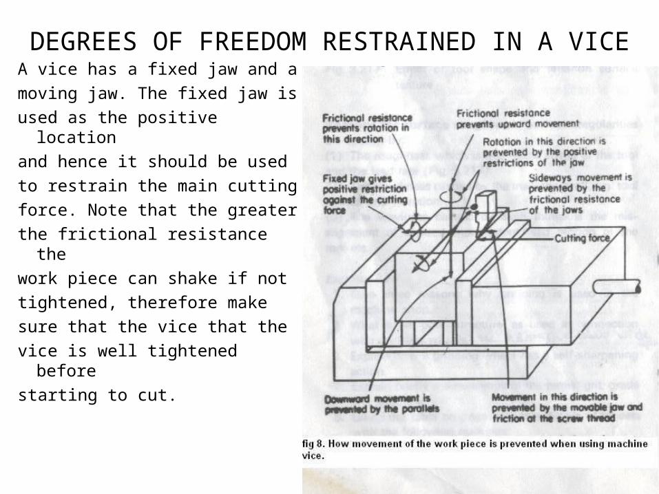
DEGREES OF FREEDOM RESTRAINED IN A VICEA vice has a fixed jaw and a moving jaw. The fixed jaw isused as the positive locationand hence it should be used to restrain the main cutting force. Note that the greater the frictional resistance the work piece can shake if not tightened, therefore make sure that the vice that the vice is well tightened before starting to cut.

DEGREE OF FREEDOM RESTRAINED IN WORK HELD BETWEEN LATHE CENTRES
The work is first prepared by drilling each end with a center drill. It is very important that the center holes are made correctly.
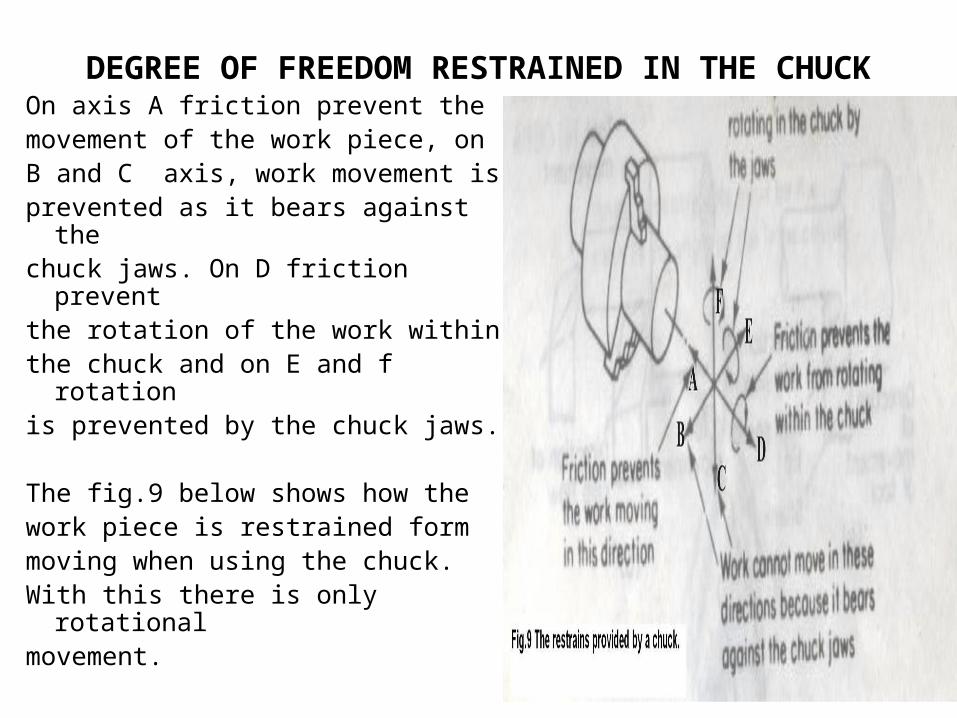
DEGREE OF FREEDOM RESTRAINED IN THE CHUCKOn axis A friction prevent themovement of the work piece, onB and C axis, work movement is prevented as it bears against the chuck jaws. On D friction prevent the rotation of the work within the chuck and on E and f rotation is prevented by the chuck jaws.
The fig.9 below shows how thework piece is restrained form moving when using the chuck.With this there is only rotational movement.
DISTINGUISHING BETWEEN RESTRAINTS FROM FRICTION
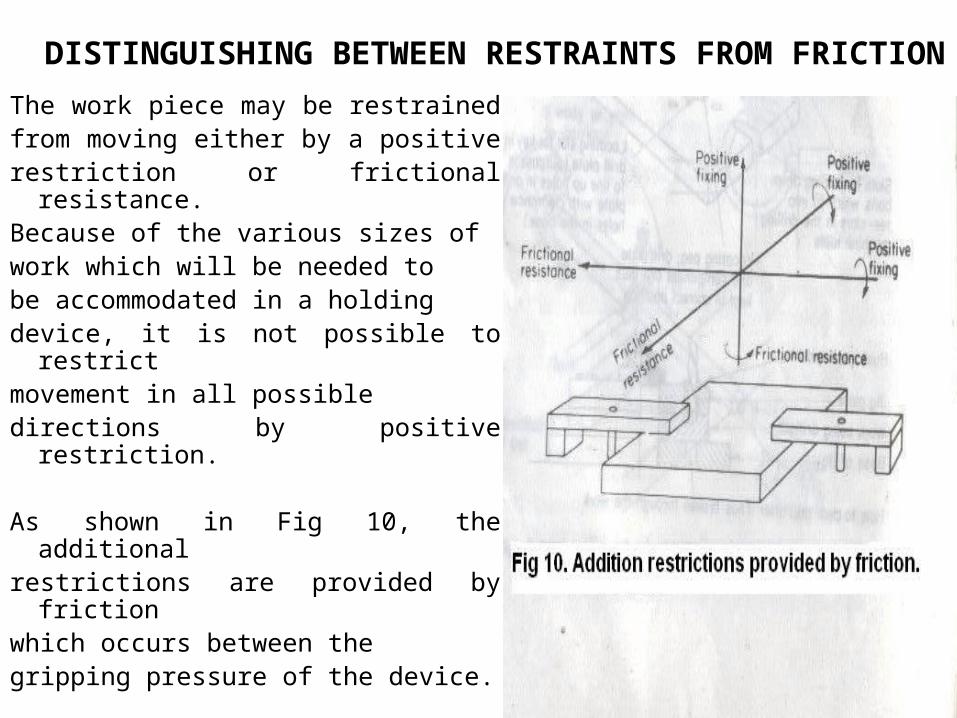
The work piece may be restrained from moving either by a positive restriction or frictional resistance. Because of the various sizes of work which will be needed to be accommodated in a holding device, it is not possible to restrict movement in all possibledirections by positive restriction.
As shown in Fig 10, the additional restrictions are provided by friction which occurs between the gripping pressure of the device.

Other form of restrain is that of solid abutment shown below. A vice has a fixed jaw and moving jaw, it is the fixed jaw or the (solid abutment) that should receive cutting force or the impart of the force. Working against the moving jaw can cause the deformation of the work piece and also the thread of the vice, as they can move in the cause of working. Fig. 11 shows how solid abutment provide restrain.
CONCLUSIONAs we have learnt, jigs and fixtures make a fairly simpleoperation out of one which would otherwise require a lot of skills and time. Jigs and fixtures are precision tools which must be taking care of. They must properly store or isolate to prevent accidental damage and they must be numbered for identification for future use.
Jigs and fixture must be cleaned, undamaged and free fromswarf and grit. Components must not be forced into a jig or fixture
So let all make it point to use jigs and fixtures correctly.

REFERENCES1. Greer A. and Howell W.H(1972) Mechanical Engineering Craft
Studies part 1 and 2.
2. Dr. Chapman W.A.J (1951) Workshop Technology Part 3.
3. Murphy J.S and Arther D (1941) General Engineering workshop Practice.
4. Donald J. Walker (1980) Engineering Productivity – Volume 1.


