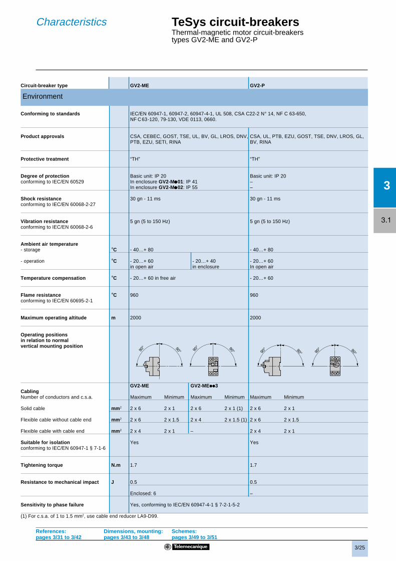
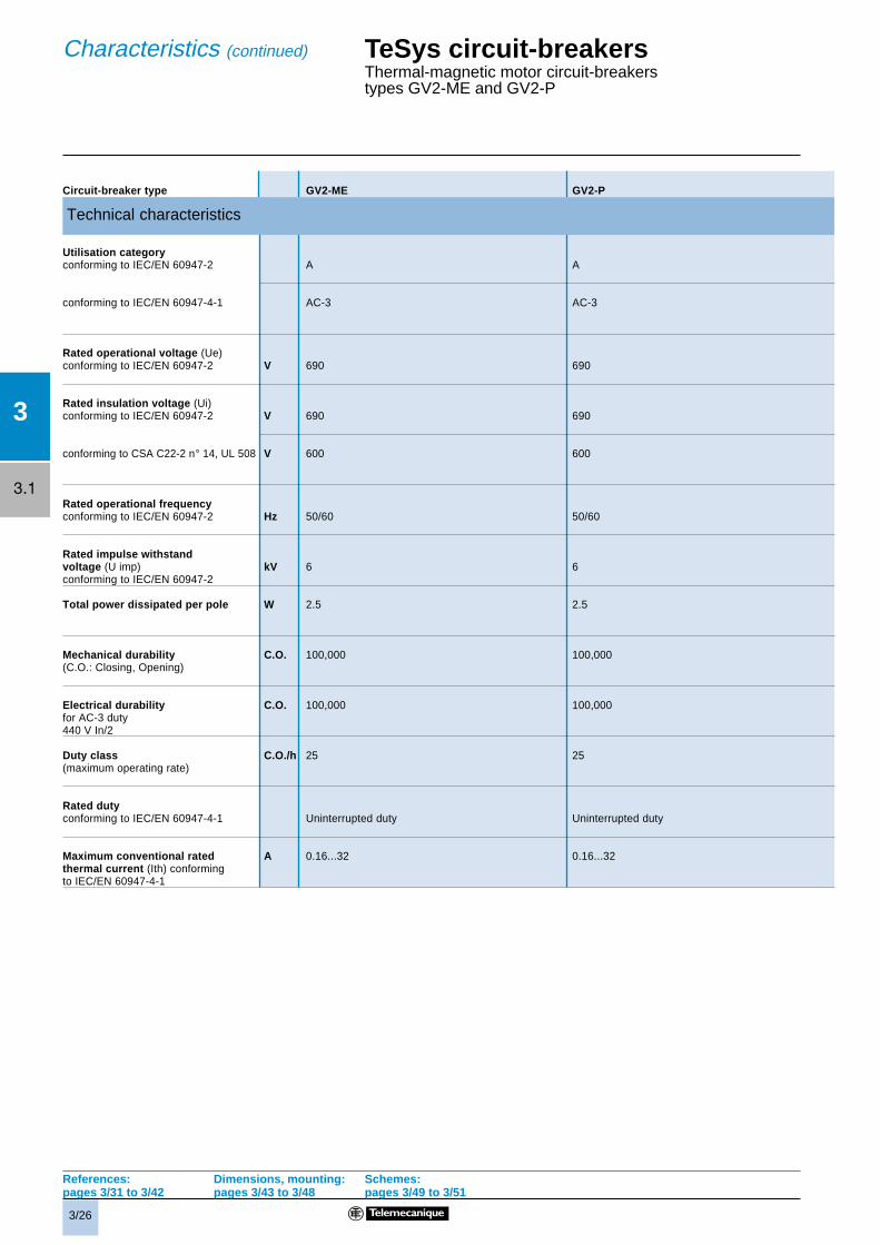
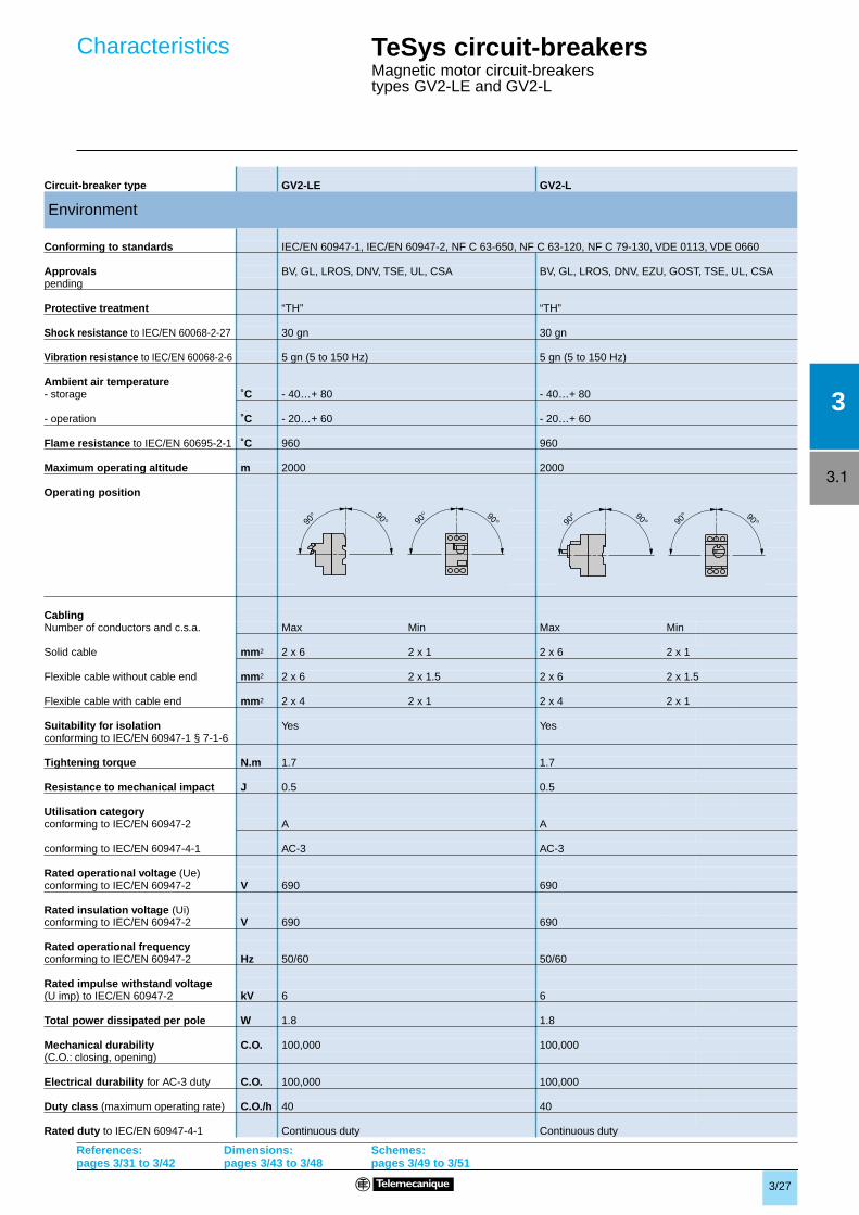
3/3 3 3.1 1 2 4 3 O I 1 2 4 O 2 3 1 I O 1 2 4 GV2-ME, GV2-P, GV3-ME and GV7-R motor circuit-breakers are 3-pole thermal-magnetic circuit-breakers specifically designed for the control and protection of motors, conforming to standards IEC/EN 60947-2 and IEC/EN 60947-4-1. These circuit-breakers are designed for connection by screw clamp terminals. Circuit-breaker GV2-ME can be supplied with spring terminal connections. These ensure secure, permanent and durable clamping that is resistant to harsh environments, vibration and impact and is even more effective when conductors without cable ends are used. Each connection can take two independent conductors. GV2-ME and GV3-ME: Pushbutton control. Energisation is controlled manually by operating the Start button “I” 1. De-energisation is controlled manually by operating the Stop button “O” 2, or automatically by the thermal-magnetic protection elements or by a voltage trip attachment. Control is manual and local when the motor circuit-breaker is used on its own. Control is automatic and remote when it is associated with a contactor. Motor protection is provided by the thermal-magnetic protection elements incorporated in the motor circuit-breaker. The magnetic elements (short-circuit protection) have a non-adjustable tripping threshold, which is equal to about 13 times the maximum setting current of the thermal trips. The thermal elements (overload protection) include automatic compensation for ambient temperature variations. The rated operational current of the motor is displayed by means of a graduated knob 4. Personnel protection is also provided. All live parts are protected against direct finger contact. The addition of an undervoltage trip allows the circuit-breaker to be de-energised in the event of an undervoltage condition. The user is therefore protected against sudden starting of the machine when normal voltage is restored, since the Start button “I” has to be pressed to restart the motor. With the addition of a shunt trip, de-energisation of the unit can be remotely controlled. The operators on both open-mounted and enclosed motor circuit-breakers can be locked in the Stop position “O” by up to 3 padlocks. Because they are suitable for isolation, these circuit-breakers, in the open position, provide an adequate isolation distance and indicate the actual position of the moving contacts by the position of the operators. These motor circuit-breakers are easily installed in any configuration thanks to their universal fixing arrangement: screw fixing or clip-on mounting on symmetrical, asymmetrical or combination rails. Connection Operation GV2-ME GV3-ME GV2-P GV7-R Protection of motors and personnel Special features TeSys circuit-breakers Thermal-magnetic motor circuit-breakers types GV2, GV3 and GV7 Presentation GV2-ME with screw clamp connections GV2-P: control by rotary knob. GV7-R: control by rocker lever. Energisation is controlled manually by moving the knob or rocker lever to position “I” 1. De-energisation is controlled manually by moving the knob or rocker lever to position “O” 2. De-energisation due to a fault automatically places the knob or rocker lever in the “Trip” position 3. Re-energisation is possible only after having returned the knob or rocker switch to position “O”. GV2-P GV2-ME with spring terminal connections GV3-ME GV7-R Characteristics: pages 3/5 to 3/7 & 3/25 to 3/30 Dimensions: pages 3/43 to 3/48 Schemes: pages 3/49 to 3/51
Transcript
3/3
3
3.1
1
2
4
3O I
12
4
O 23
1
IO 1
2
4
GV2-ME, GV2-P, GV3-ME and GV7-R motor circuit-breakers are 3-pole thermal-magnetic circuit-breakers
specificallydesigned for the control and protection of motors,
conforming to standards IEC/EN 60947-2 and IEC/EN 60947-4-1
.
These circuit-breakers are designed for connection by screw clamp terminals.Circuit-breaker GV2-ME can be supplied with
spring terminal
connections.These ensure secure, permanent and durable clamping that is resistant to harsh environments, vibration and impact andis even more effective when conductors without cable ends are used. Each connection can take two independentconductors.
GV2-ME and GV3-ME: Pushbutton control.Energisation is controlled manually by operating the Startbutton “I”
1
.De-energisation is controlled manually by operating theStop button “O”
2
, or automatically by the thermal-magneticprotection elements or by a voltage trip attachment.
Control is manual and local when the motor circuit-breaker is used on its own.Control is automatic and remote when it is associated with a contactor.
Motor protection is provided by the thermal-magnetic protection elements incorporated in the motor circuit-breaker.The
magnetic
elements (short-circuit protection) have a non-adjustable tripping threshold, which is equal to about 13times the maximum setting current of the thermal trips.The
thermal
elements (overload protection) include automatic compensation for ambient temperature variations.The rated operational current of the motor is displayed by means of a graduated knob
4
.
Personnel protection is also provided. All live parts are protected against direct finger contact.
The addition of an undervoltage trip allows the circuit-breaker to be de-energised in the event of an undervoltagecondition. The user is therefore protected against sudden starting of the machine when normal voltage is restored, sincethe Start button “I” has to be pressed to restart the motor.
With the addition of a shunt trip, de-energisation of the unit can be remotely controlled.
The operators on both open-mounted and enclosed motor circuit-breakers can be locked in the Stop position “O” by upto 3 padlocks.
Because they are suitable for isolation, these circuit-breakers, in the open position, provide an adequate isolation distanceand indicate the actual position of the moving contacts by the position of the operators.
These motor circuit-breakers are easily installed in any configuration thanks to their universal fixing arrangement: screwfixing or clip-on mounting on symmetrical, asymmetrical or combination rails.
Connection
Operation
GV2-ME GV3-ME GV2-P GV7-R
Protection of motors and personnel
Special features
TeSys circuit-breakers
Thermal-magnetic motor circuit-breakerstypes GV2, GV3 and GV7
Presentation
GV2-ME with screw clamp connections
GV2-P: control by rotary knob.GV7-R: control by rocker lever.Energisation is controlled manually by moving the knobor rocker lever to position “I”
1
.De-energisation is controlled manually by moving theknob or rocker lever to position “O”
2
.De-energisation due to a fault automatically places the knobor rocker lever in the “Trip” position
3
. Re-energisation ispossible only after having returned the knob or rocker switchto position “O”.
GV2-P
GV2-ME with spring terminal connections
GV3-ME
GV7-R
Characteristics: pages 3/5 to 3/7 & 3/25 to 3/30
Dimensions:pages 3/43 to 3/48
Schemes:pages 3/49 to 3/51
3/4
3
3.1
Coordination (according to standard IEC/EN 60947-4-1)
The standard defines the degree of acceptable damage to the equipment following a short-circuit.Standard IEC/EN 60947-4-1 (motor-starters) defines 2 types
Type 1 Damage to motor-starter components is The fault current has been successfully interrupted. coordination accepted. No damage has been caused to persons or to
installations. Type 2 Welding of the contactor or motor-starter coordination contacts is accepted providing they can
be easily separated.
Coordination table for GV2 + contactors: see the Technical & Application guide at www.schneider.co.uk.
Iq = rated conditional short-circuit current (kA)- that the circuit-breaker can interrupt- that the associated motor-starter components can withstand without damage.
Suitability for isolation
According to standard IEC/EN 60947-1, sub-clause 7-1-6 (additional safety requirements for equipment suitable forisolation):
Equipment suitable for isolation shall provide in the open position and isolating distance in accordance with therequirements necessary to satisfy the isolating function and shall be fitted with an indicating device indicating the positionof the moving contacts. This position indicator shall be connected to the moving contacts in a reliable way; the handlemay form such an indicator, providing it cannot indicate the open position when released unless all the moving contactsare in the open position.
Breaking capacity (according to standard IEC/EN 60947-2)
Breaking capacity for which the prescribed conditions according to a specified test sequence do not include the capabilityof the circuit-breaker to carry its rated current continuously following the sequence of operations )O-t-CO.
Ics: Rated service short-circuit breaking capacity
Breaking capacity for which the prescribed conditions according to a specified test sequence include the capability of thecircuit-breaker to carry its rated current continuously following the sequence of operations O-t-CO-t-CO.
It is expressed as a percentage of Icu (25, 50, 75 or 100%).In operational conditions , the short-circuit currents normally encountered rarely exceed 25 to 50% of the prospectiveshort-circuit current at the point of installation of the circuit-breaker.
Other definitions
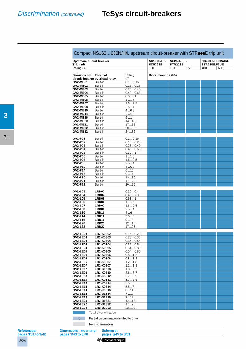
Discrimination (selectivity)
Discrimination of protective devices requires that protection against a fault arising at any point of the network is effectedby the nearest device on the supply side of the fault.
Discrimination may be total or partial. In the latter case the overcurrent limit must be defined.See pages 3/20 to 3/24.
Cascading
Where two separate protective devices in series operate at the same time under short circuit fault conditions, the breakingcapacity lcu of the downstream device is increased.See page 3/20.
Current limiting
By the use of additional poles operating in series with the main poles, the overall breaking capacity lcu of a motor circuit-breaker is substantially increased. A single current limiting block may be used in conjunction with a number of motorcircuit-breakers up to the 63 A thermal limit.See page 3/6.
Sensitivity to phase loss (according to standard IEC/EN 60947-4-1, sub-clause 7.2.1.5.2)
Limits of operation of 3-pole thermal overload relays energised on two poles: With the overload relay energised on twopoles at 1.0 times the current setting (Ir) and on one pole at 0.9 Ir, tripping shall not occur in less than 2 hours startingfrom the cold state at 20 o C.
When the value Ir flowing in two poles is increased to 1.15 Ir and the third pole is de-energised, tripping shall occur in lessthan 2 hours. See curves, pages 3/8 to 3/10.
x
TeSys circuit-breakersDefinitions,comments
3/5
3
3.1
TeSys circuit-breakers
Thermal-magnetic motor circuit-breakerstypes GV2-ME and GV2-P(Also applies to GV2-RT. Use GV2-ME tableeg: for GV2-RT14 use GV2-ME14 data)
440 V aM A g g g 50 50 50 50 63 63 g g g g g 50 63 80 80
gG A g g g 63 63 63 63 80 80 g g g g g 63 80 100 100
500 V aM A g g g 50 50 50 50 50 50 g g g g 50 50 50 50 50
gG A g g g 63 63 63 63 63 63 g g g g 63 63 63 63 63
690 V aM A g 16 25 32 32 40 40 40 40 g 20 25 40 40 50 50 50 50
gG A g 20 32 40 40 50 50 50 50 g 25 32 50 50 63 63 63 63
Characteristics
References:pages 3/31 to 3/42
Dimensions:pages 3/43 to 3/48
Schemes:pages 3/49 to 3/51
3/6
3
3.1
TeSys circuit-breakersThermal-magnetic motor circuit-breakerstypes GV2-ME and GV2-P(Also applies to GV2-RT. Use GV2-ME tableeg: for GV2-RT14 use GV2-ME14 data)
Breaking capacity of GV2-ME and GV2-P (used in association with current limiter GV1-L3)
Rating A 0.1…1.6 2.5 4 6.3 10 14 18 23 25 32Cable protection against thermalstress in the event of short-circuit(PVC insulated copper cables)
Minimum 1 mm2 p p p ≤ 10 kA ≤ 6 kA (2) (2) (2) (2) (2)c.s.a.protected 1.5 mm2 p p p ≤ 20 kA ≤ 10 kA (2) (2) (2) (2) (2)at 40 ˚Cat Isc max. 2.5 mm2 p p p p p p p p p (2)
4…6 mm2 p p p p p p p p p pg > 100 kA. p Cable c.s.a. protected.
(1) As % of Icu. (2) Cable c.s.a. not protected. (3) With limiter LA9-LB920.
Characteristics (continued)
References:pages 3/31 to 3/42
Dimensions:pages 3/43 to 3/48
Schemes:pages 3/49 to 3/51
3/7
3
3.1
TeSys circuit-breakersMagnetic motor circuit-breakerstypes GV2-LE and GV2-L
(1) As % of Icu(2) Cable c.s.a. not protectedp Cable c.s.a. protected
Rating A 0.4 2.5 4 6.3 10 14 18 25 32 0.4 2.5 4 6.3 10 14 18 25 32 to to
1.6 1
Breaking capacity 230/ Icu kA g g g g g g g 50 50 g g g g g g g 50 50to IEC/EN 60947-2 240 V
Ics g g g g g g g 100 100 g g g g g g g 100 100% (1)
400/ Icu kA g g g g g 15 15 15 10 g g g g g 50 50 50 50415 V
Ics g g g g g 50 50 40 50 g g g g g 50 50 50 50% (1)
440 V Icu kA g g g 50 15 8 8 6 6 g g g g 20 20 20 20 20
Ics g g g 100 100 50 50 50 50 g g g g 75 75 75 75 75% (1)
500 V Icu kA g g g 50 10 6 6 4 4 g g g g 10 10 10 10 10
Ics g g g 100 100 75 75 75 75 g g g g 100 75 75 75 75% (1)
690 V Icu kA g 3 3 3 3 3 3 3 3 g 4 4 4 4 4 4 4 4
Ics g 75 75 75 75 75 75 75 75 g 100 100 100 100 100 100 100 100% (1)
Associated fuses (if required)If Isc > breaking capacity Icuto IEC/EN 60947-2 230/ aM A g g g g g g g 80 80 g g g g g g g 100 100
240 V gG A g g g g g g g 100 100 g g g g g g g 125 125
400/ aM A g g g g g 63 63 80 80 g g g g g 80 100 100 100415 V
gG A g g g g g 80 80 100 100 g g g g g 100 125 125 125
440 V aM A g g g 50 50 50 50 63 63 g g g g 50 63 80 80 80
gG A g g g 63 63 63 63 80 80 g g g g 63 80 100 100 100
500 V aM A g g g 50 50 50 50 50 50 g g g g 50 50 50 50 50
gG A g g g 63 63 63 63 63 63 g g g g 63 63 63 63 63
690 V aM A g 16 25 32 32 40 40 40 40 g 20 25 40 40 50 50 50 50
gG A g 20 32 40 40 50 50 50 50 g 25 32 50 50 63 63 63 63
Cable protection against thermalstress in the event of short-circuit(PVC insulated copper cables)
Minimum c.s.a. 1 mm2 kA p p p ≤ 10 ≤ 6 (2) (2) (2) (2) p p p ≤ 10 ≤ 6 (2) (2) (2) (2)protected at 40 ˚Cand at Isc max 1.5 mm2 kA p p p ≤ 20 ≤ 10 (2) (2) (2) (2) p p p ≤ 20 ≤ 10 (2) (2) (2) (2)
2.5 mm2 p p p p p p p p (2) p p p p p p p p (2)
4…6 mm2 p p p p p p p p p p p p p p p p p pg > 100 kA
Characteristics
References:pages 3/31 to 3/42
Dimensions:pages 3/43 to 3/48
Schemes:pages 3/49 to 3/51
3/8
3
3.1
0,001
0,1
1
10
100
0,01
1 1,5 10 100
1000
10 000
32
1
TeSys protection components 3
Thermal-magnetic motor circuit-breakers types GV2-ME and GV2-P
Average operating time at 20 ˚C according to multiples of the setting current
1 3 poles from cold state2 2 poles from cold state3 3 poles from hot state
Thermal-magnetic tripping curves for GV2-ME and GV2-P
Curves
References:pages 3/31 to 3/42
Dimensions:pages 3/43 to 3/48
Schemes:pages 3/49 to 3/51
Time (s)
x setting current (Ir)
3/9
3
3.1
x setting current (Ir)
10
10 000
1
0,1
0,0011 10 100
1000
100
0,01
21
3
TeSys protection components 3
Thermal-magnetic motor circuit-breakers type GV2-RT
1 3 poles from cold state2 2 poles from cold state3 3 poles from hot state
Thermal-magnetic tripping curves for GV2-RT
Curves
Time (s)
References:pages 3/31 to 3/42
Dimensions:pages 3/43 to 3/48
Schemes:pages 3/49 to 3/51
3/10
3
3.1
10
10 000
1
0,1
0,0011 10 100
1000
100
0,01
32
1
TeSys protection components 3
Magnetic motor circuit-breakers types GV2-L and GV2-LE
Average operating time at 20˚C according to multiples of the setting current
1 3 poles from cold state2 2 poles from cold state3 3 poles from hot state
Tripping curves for GV2-L or LE combined with thermal overload relay LRD or LR2-K
Curves
Time (s)
References:pages 3/31 to 3/42
Dimensions:pages 3/43 to 3/48
Schemes:pages 3/49 to 3/51
x setting current (Ir)
3/11
3
3.1
1
6
5
4
3
7
8
9
10
11
2
100
10
1
0,10,1 1 10 100
cos
= 0
.95
= 0.
9
= 0.
8
= 0.
7=
0.5
= 0.
3
= 0.
25
15 (12)
TeSys protection components 3
Thermal-magnetic motor circuit-breakers types GV2-ME and GV2-P
3-phase 400/415 V
Dynamic stress
I peak = f (prospective Isc) at 1.05 Ue = 435 V
Current limitation on short-circuit for GV2-ME and GV2-P
1 Maximum peak current 7 6-10 A2 24-32 A 8 4-6.3 A3 20-25 A 9 2.5-4 A4 17-23 A 10 1.6-2.5 A5 13-18 A 11 1-1.6 A6 9-14 A 12 Limit of rated ultimate breaking capacity on short-circuit
of GV2-ME (14, 18, 23 and 25 A ratings)
Curves (continued)
Limited peak current (kA)
References:pages 3/31 to 3/42
Dimensions:pages 3/43 to 3/48
Schemes:pages 3/49 to 3/51
Prospective Isc (kA)
3/12
3
3.1
100
10
1
0,10,1 1 100
1
5
4
3
8
9
10
7
6
cos
= 0
.95
= 0.
9
= 0.
8
= 0.
7=
0.5
= 0.
3
= 0.
25
151011
2
TeSys protection components 3
Magnetic motor circuit-breakers types GV2-L and GV2-LE
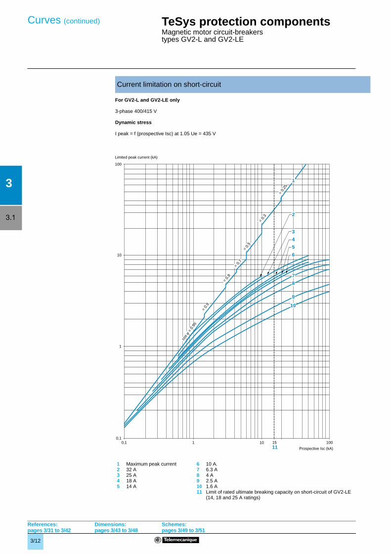
For GV2-L and GV2-LE only
3-phase 400/415 V
Dynamic stress
I peak = f (prospective Isc) at 1.05 Ue = 435 V
Current limitation on short-circuit
1 Maximum peak current 6 10 A.2 32 A 7 6.3 A3 25 A 8 4 A4 18 A 9 2.5 A5 14 A 10 1.6 A
11 Limit of rated ultimate breaking capacity on short-circuit of GV2-LE(14, 18 and 25 A ratings)
Curves (continued)
Limited peak current (kA)
Prospective Isc (kA)
References:pages 3/31 to 3/42
Dimensions:pages 3/43 to 3/48
Schemes:pages 3/49 to 3/51
3/13
3
3.1
100
10
1
0,10,1 1 10 100
cos
= 0
.95
= 0.
9
= 0.
8
= 0.
7=
0.5
= 0.
3
= 0.
25
15
11
1
2
3
4
5
6
7
8
9
10
References:pages 3/31 to 3/42
Dimensions:pages 3/43 to 3/48
Schemes:pages 3/49 to 3/51
TeSys protection components 3
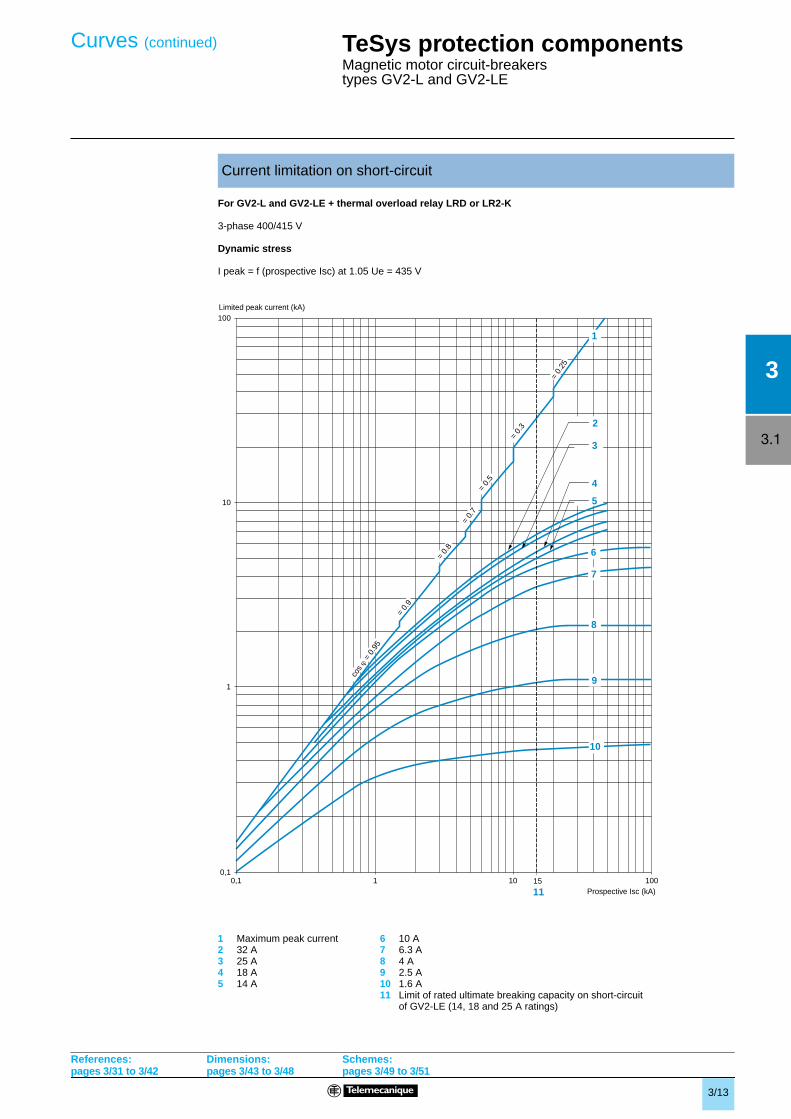
Magnetic motor circuit-breakers types GV2-L and GV2-LE
For GV2-L and GV2-LE + thermal overload relay LRD or LR2-K
3-phase 400/415 V
Dynamic stress
I peak = f (prospective Isc) at 1.05 Ue = 435 V
Current limitation on short-circuit
1 Maximum peak current 6 10 A2 32 A 7 6.3 A3 25 A 8 4 A4 18 A 9 2.5 A5 14 A 10 1.6 A
11 Limit of rated ultimate breaking capacity on short-circuitof GV2-LE (14, 18 and 25 A ratings)
Curves (continued)
Limited peak current (kA)
Prospective Isc (kA)
3/14
3
3.1
100
10
1
0,1
0,010,1 1 10 100
345
6
7
8
9
10
21
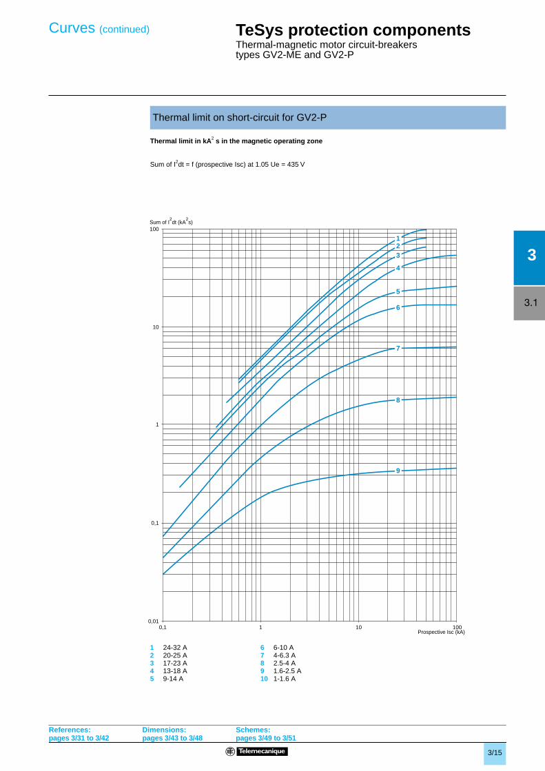
Thermal limit in KA2 s in the magnetic operating zone
Sum of I2dt = f (prospective Isc) at 1.05 Ue = 435 V
Thermal limit on short-circuit for GV2-ME
1 24-32 A 6 6-10 A2 20-25 A 7 4-6.3 A3 17-23 A 8 2.5-4 A4 13-18 A 9 1.6-2.5 A5 9-14 A 10 1-1.6 A
TeSys protection components 3
Thermal-magnetic motor circuit-breakers types GV2-ME and GV2-P
Curves (continued)
Prospective Isc (kA)
References:pages 3/31 to 3/42
Dimensions:pages 3/43 to 3/48
Schemes:pages 3/49 to 3/51
Sum of I2dt (kA
2s)
3/15
3
3.1
100
10
1
0,1
0,010,1 1 10 100
123
4
5
6
7
8
9
TeSys protection components 3
Thermal-magnetic motor circuit-breakers types GV2-ME and GV2-P
Thermal limit in kA2 s in the magnetic operating zone
Sum of I2dt = f (prospective Isc) at 1.05 Ue = 435 V
Thermal limit on short-circuit for GV2-P
1 24-32 A 6 6-10 A2 20-25 A 7 4-6.3 A3 17-23 A 8 2.5-4 A4 13-18 A 9 1.6-2.5 A5 9-14 A 10 1-1.6 A
Curves (continued)
Sum of I2dt (kA
2s)
Prospective Isc (kA)
References:pages 3/31 to 3/42
Dimensions:pages 3/43 to 3/48
Schemes:pages 3/49 to 3/51
3/16
3
3.1
100
10
1
0,1
0,010,1 1 10 100
1234
5
6
8
7
TeSys protection components 3
Magnetic motor circuit-breakers types GV2-L and GV2-LE
Thermal limit in kA2 s in the magnetic operating zone
Sum of I2dt = f (prospective Isc) at 1.05 Ue = 435 V
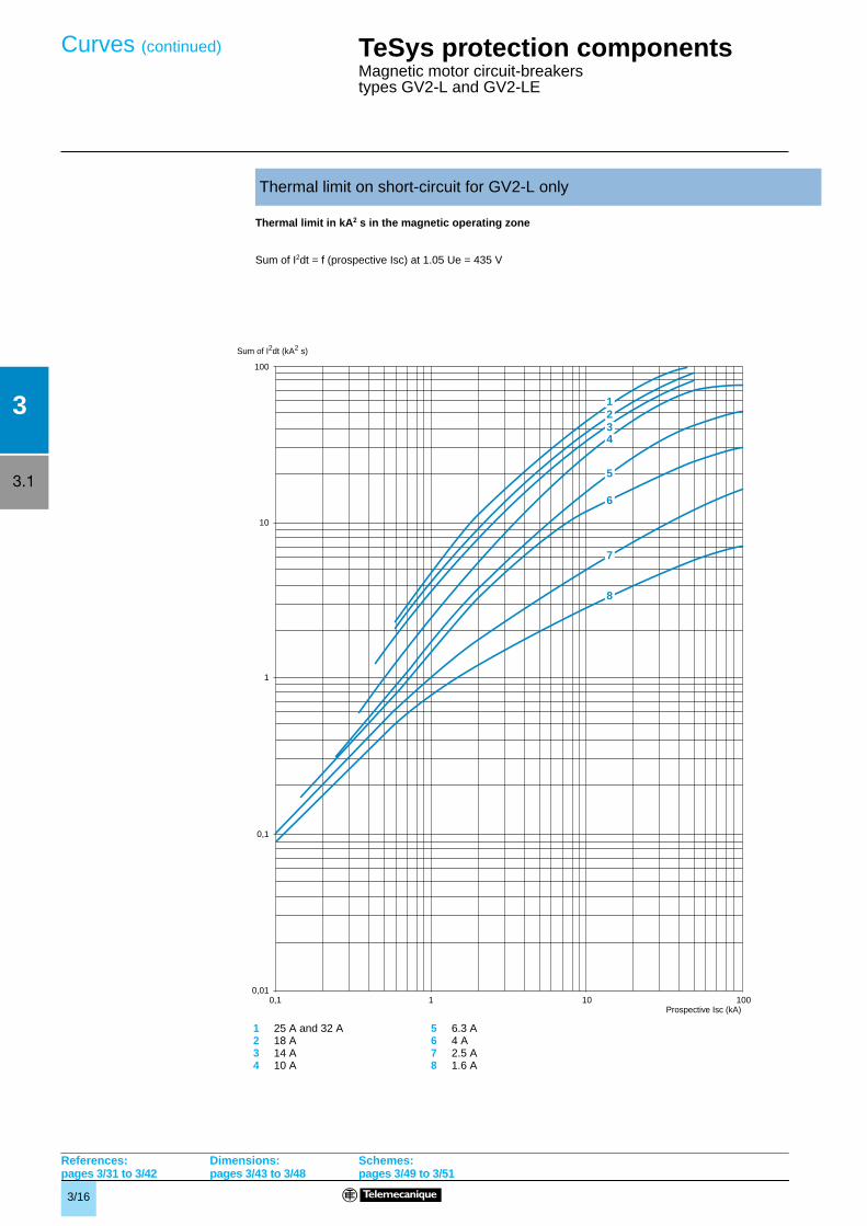
Thermal limit on short-circuit for GV2-L only
1 25 A and 32 A 5 6.3 A2 18 A 6 4 A3 14 A 7 2.5 A4 10 A 8 1.6 A
Curves (continued)
Sum of I2dt (kA2 s)
References:pages 3/31 to 3/42
Dimensions:pages 3/43 to 3/48
Schemes:pages 3/49 to 3/51
Prospective Isc (kA)
3/17
3
3.1
100
10
1
0,1
0,010,1 1 10 100
1 2
3
4
5
6
7
8
9
TeSys protection components 3
Magnetic motor circuit-breakers types GV2-L and GV2-LE
Thermal limit in kA2 s in the magnetic operating zone
Sum of I2dt = f (prospective Isc) at 1.05 Ue = 435 V
Thermal limit on short-circuit for GV2-LE only
1 32 A 6 6.3 A2 25 A 7 4 A3 18 A 8 2.5 A4 14 A 9 1.6 A5 10 A
Curves (continued)
Sum of I2dt (kA2 s)
References:pages 3/31 to 3/42
Dimensions:pages 3/43 to 3/48
Schemes:pages 3/49 to 3/51
Prospective Isc (kA)
3/18
3
3.1
100
10
1
0,1
0,010,1 1 10 100
2
3
4
5
6
7
8
9
15
1
10
TeSys protection components 3
Magnetic motor circuit-breakers types GV2-L and GV2-LE
For GV2-L and GV2-LE + thermal overload relay LRD or LR2-K
Thermal limit in kA2 s in the magnetic operating zone
Sum of I2dt = f (prospective Isc) at 1.05 Ue = 435 V
Thermal limit on short-circuit
1 32 A (GV2-LE32) 7 4 A2 25 A and 32 A (GV2-L32) 8 2.5 A3 18 A 9 1.6 A4 14 A 10 Limit of rated ultimate breaking capacity on short-circuit
of GV2-LE (14, 18 and 25 A ratings)5 10 A6 6.3 A
Curves (continued)
Sum of I2dt (kA2 s)
Prospective Isc (kA)
References:pages 3/31 to 3/42
Dimensions:pages 3/43 to 3/48
Schemes:pages 3/49 to 3/51
3
3.1
3/19
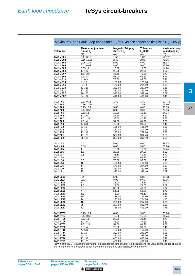
Maximum Earth Fault Loop Impedance ZS for 0.4s disconnection time with U0 230V (1)
Thermal Adjustment Magnetic Tripping Tolerance Maximum LoopReference Range In Current Im Im+20% Impedance Zs
GV2-RT03 0.25...0.4 8.00 9.60 23.96GV2-RT04 0.4...0.63 13.00 15.60 14.74GV2-RT05 0.63...1 22.00 26.40 8.71GV2-RT06 1...1.6 33.00 39.60 5.81GV2-RT07 1.6...2.5 51.00 61.20 3.76GV2-RT08 2.5...4 78.00 93.60 2.46GV2-RT10 4...6.3 138.00 165.60 1.39GV2-RT14 6...10 200.00 240.00 0.96GV2-RT16 9...14 280.00 336.00 0.68GV2-RT20 13...18 400.00 480.00 0.48GV2-RT21 17...23 400.00 480.00 0.48(1) Whilst the IEE Regulations provide for a disconnection time of 5s for fixed equipment, the value of impedance obtainedwill limit the current to a level which may affect the starting characteristics of the motor.
References: Dimensions, mounting: Schemes:pages 3/31 to 3/42 pages 3/43 to 3/48 pages 3/49 to 3/51
TeSys circuit-breakersEarth loop impedance
3
3.1
3/20
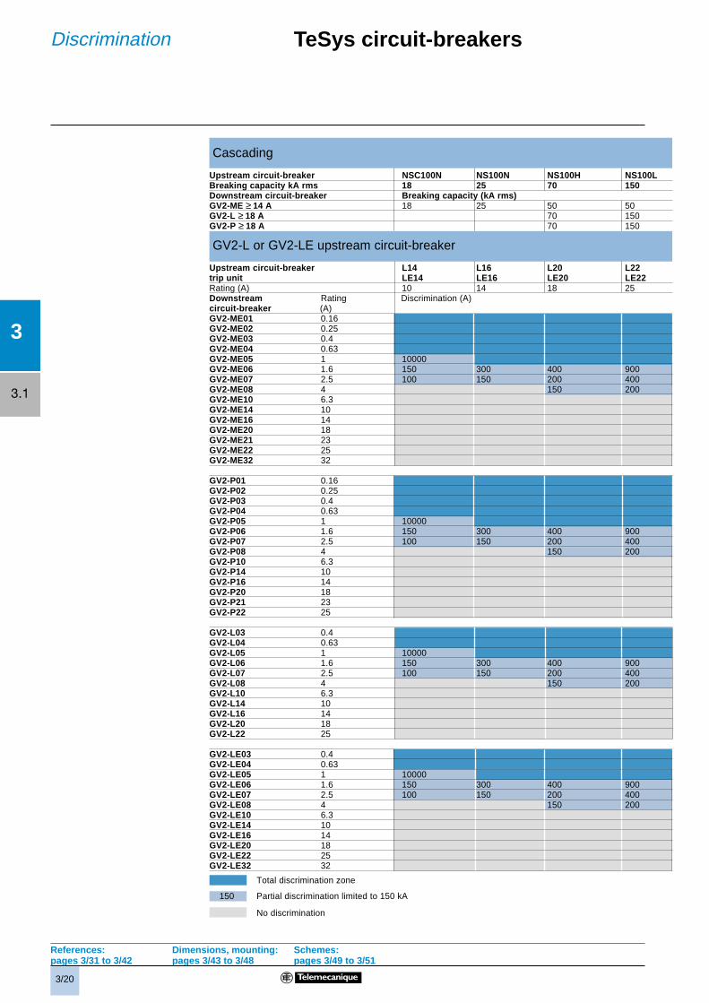
Cascading
Upstream circuit-breaker NSC100N NS100N NS100H NS100LBreaking capacity kA rms 18 25 70 150Downstream circuit-breaker Breaking capacity (kA rms)GV2-ME ≥ 14 A 18 25 50 50GV2-L ≥ 18 A 70 150GV2-P ≥ 18 A 70 150
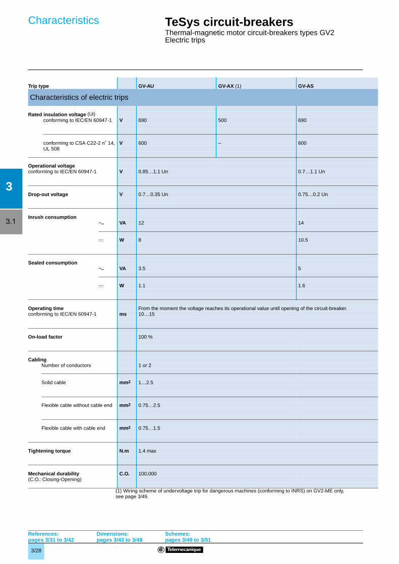
(1) Wiring scheme of undervoltage trip for dangerous machines (conforming to INRS) on GV2-ME only, see page 3/49.
Characteristics
References: pages 3/31 to 3/42
Dimensions:pages 3/43 to 3/48
Schemes:pages 3/49 to 3/51
3/29
3
3.1
TeSys circuit-breakersThermal-magnetic motor circuit-breakers types GV2Auxiliary contacts
instantaneous auxiliary contacts
(1) For application example of fault signalling contact and short-circuit signalling contact, see page 3/49.(2) Add an RC circuit type LA4-D to the load terminals, see page 2/87.
Rated insulation voltage (Ui)(associated insulation coordination) V 690 690 250 (690 in relation toto IEC/EN 60947-1 main circuit)to CSA C22-2 n˚ 14 and UL 508 V 600 300 300
Conventional rated thermal current(Ith) to IEC/EN 60947-5-1 A 6 2.5 2.5to CSA C22-2 n˚ 14 and UL 508 A 5 1 1
Mechanical durability C.O. 100,000 1000 100,000
Operational power and currentto IEC/EN 60947-5-1, a.c. operation AC-15/100,000 C.O. AC-14/1000 C.O. AC-15/100,000 C.O.
Operational power, normal conditions W 140 240 180 140 120 – – 24 15 9 – 24 15 9 –
Occasional breaking and making W 240 360 240 210 180 – – 100 50 50 – 100 50 50 –capacities, abnormal conditions
Rated operational current (Ie) A 6 5 3 1.3 0.5 – – 1 0.3 0.15 – 1 0.3 0.15 –
Low level switching contact reliability GV-AE: Number of failures for for “n” million operating cycles (17 V-5 mA): = 10-6
Minimum operational conditions V 17d.c. operation mA 5
Short-circuit protection By GB2-CBpp circuit-breaker (rating according to operational current GB2-CB06 or for Ue ≤ 415 V) or by gG fuse 10 A max gG fuse 10 A max
Cabling, screw clamp terminalsNumber of conductors 1 2Solid cable mm2 1…2.5 1…2.5Flexible cable without cable end mm2 0.75…2.5 0.75…2.5Flexible cable with cable end mm2 0.75…1.5 0.75…1.5Tightening torque N.m 1.4 max 1.4 max
Cabling, spring terminal connections GV-AN onlyFlexible cable without cable end mm2 0.75…2.5 0.75…2.5 – 0.75…1.5
Contact operation,
Operation of faultsignalling contacts
GV-AM11Change of state following tripping on short-circuit.
GV-AD10pp and GV-AD01ppChange of state following trippingon short-circuit, overload or undervoltage.
Characteristics
References: pages 3/31 to 3/42
Dimensions:pages 3/43 to 3/48
Schemes:pages 3/49 to 3/51
GV-AN20
GV-AN11
GV-AE1
Power pole
GV-AE20
Contact open
Contact closed
GV-ADpp01
GV-ADpp10
GV-AE11
0 1
N/ON/O
N/ON/C
N/ON/C
N/ON/O
N/ON/C
N/O
N/C
3/30
3
3.1
TeSys circuit-breakersThermal-magnetic motor circuit-breakers types GV2Auxiliary contacts
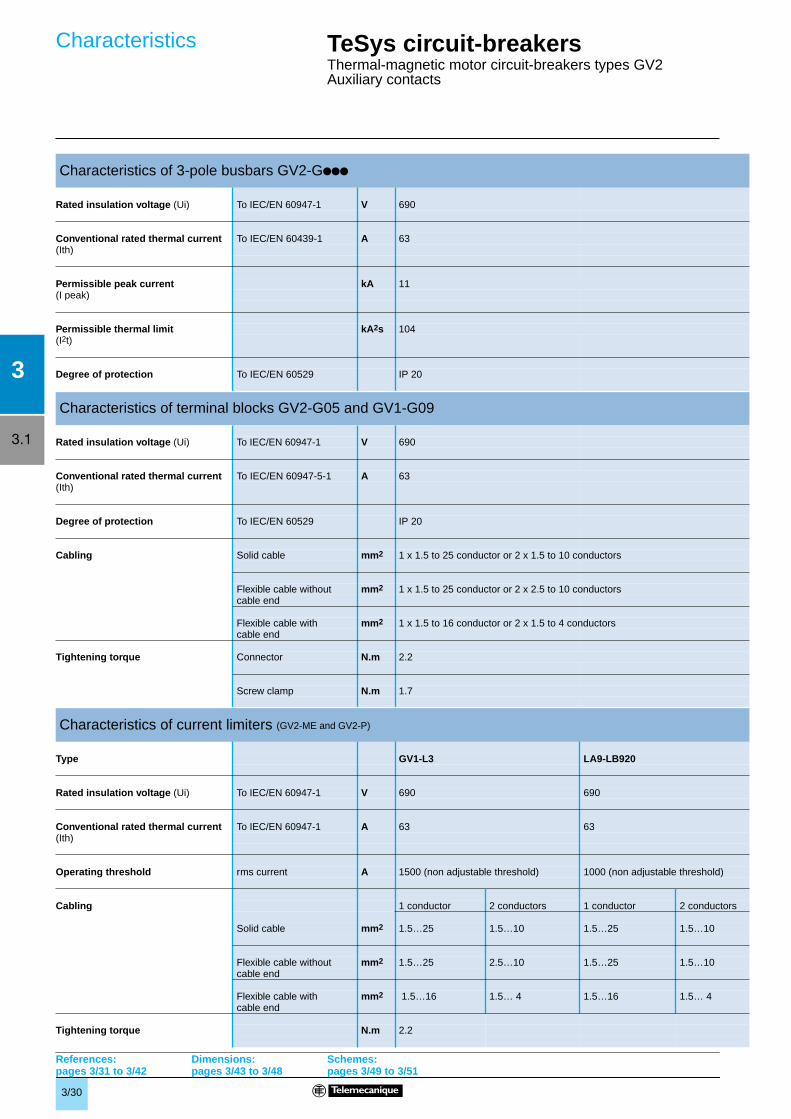
Characteristics of 3-pole busbars GV2-Gppp
Rated insulation voltage (Ui) To IEC/EN 60947-1 V 690
Conventional rated thermal current To IEC/EN 60439-1 A 63(Ith)
Permissible peak current kA 11(I peak)
Permissible thermal limit kA2s 104(I2t)
Degree of protection To IEC/EN 60529 IP 20
Characteristics of terminal blocks GV2-G05 and GV1-G09
Rated insulation voltage (Ui) To IEC/EN 60947-1 V 690
Conventional rated thermal current To IEC/EN 60947-5-1 A 63(Ith)
Degree of protection To IEC/EN 60529 IP 20
Cabling Solid cable mm2 1 x 1.5 to 25 conductor or 2 x 1.5 to 10 conductors
Flexible cable without mm2 1 x 1.5 to 25 conductor or 2 x 2.5 to 10 conductorscable end
Flexible cable with mm2 1 x 1.5 to 16 conductor or 2 x 1.5 to 4 conductorscable end
Tightening torque Connector N.m 2.2
Screw clamp N.m 1.7
Characteristics of current limiters (GV2-ME and GV2-P)
Type GV1-L3 LA9-LB920
Rated insulation voltage (Ui) To IEC/EN 60947-1 V 690 690
Conventional rated thermal current To IEC/EN 60947-1 A 63 63(Ith)
Operating threshold rms current A 1500 (non adjustable threshold) 1000 (non adjustable threshold)
Flexible cable without mm2 1.5…25 2.5…10 1.5…25 1.5…10cable end
Flexible cable with mm2 1.5…16 1.5… 4 1.5…16 1.5… 4cable end
Tightening torque N.m 2.2
Characteristics
References: pages 3/31 to 3/42
Dimensions:pages 3/43 to 3/48
Schemes:pages 3/49 to 3/51
3/31
3
3.1
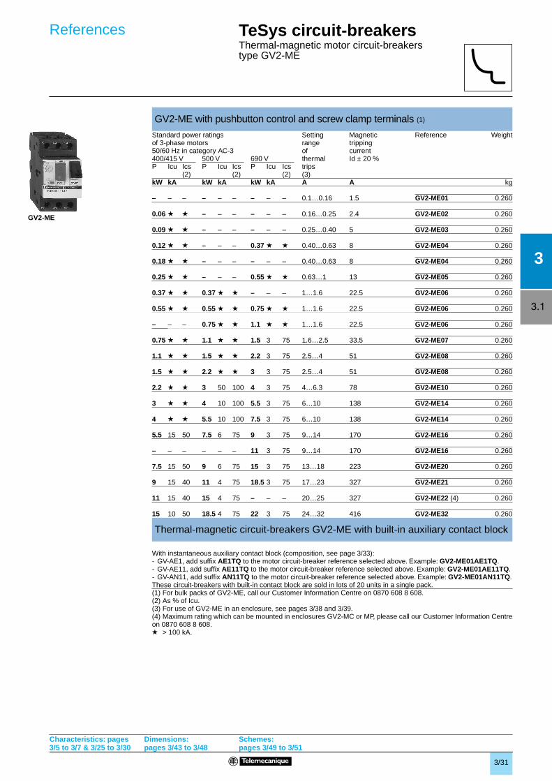
TeSys circuit-breakersThermal-magnetic motor circuit-breakers type GV2-ME
With instantaneous auxiliary contact block (composition, see page 3/33):- GV-AE1, add suffix AE1TQ to the motor circuit-breaker reference selected above. Example: GV2-ME01AE1TQ.- GV-AE11, add suffix AE11TQ to the motor circuit-breaker reference selected above. Example: GV2-ME01AE11TQ.- GV-AN11, add suffix AN11TQ to the motor circuit-breaker reference selected above. Example: GV2-ME01AN11TQ.These circuit-breakers with built-in contact block are sold in lots of 20 units in a single pack.(1) For bulk packs of GV2-ME, call our Customer Information Centre on 0870 608 8 608.(2) As % of Icu.(3) For use of GV2-ME in an enclosure, see pages 3/38 and 3/39.(4) Maximum rating which can be mounted in enclosures GV2-MC or MP, please call our Customer Information Centreon 0870 608 8 608.
GV2-ME with pushbutton control and screw clamp terminals (1)
Standard power ratings Setting Magnetic Reference Weightof 3-phase motors range tripping50/60 Hz in category AC-3 of current400/415 V 500 V 690 V thermal Id ± 20 %P Icu Ics P Icu Ics P Icu Ics trips
(2) (2) (2) (3)kW kA kW kA kW kA A A kg
– – – – – – – – – 0.1…0.16 1.5 GV2-ME01 0.260
0.06 g g – – – – – – 0.16…0.25 2.4 GV2-ME02 0.260
0.09 g g – – – – – – 0.25…0.40 5 GV2-ME03 0.260
0.12 g g – – – 0.37 g g 0.40…0.63 8 GV2-ME04 0.260
0.18 g g – – – – – – 0.40…0.63 8 GV2-ME04 0.260
0.25 g g – – – 0.55 g g 0.63…1 13 GV2-ME05 0.260
0.37 g g 0.37 g g – – – 1…1.6 22.5 GV2-ME06 0.260
0.55 g g 0.55 g g 0.75 g g 1…1.6 22.5 GV2-ME06 0.260
– – – 0.75 g g 1.1 g g 1…1.6 22.5 GV2-ME06 0.260
0.75 g g 1.1 g g 1.5 3 75 1.6…2.5 33.5 GV2-ME07 0.260
Thermal-magnetic circuit-breakers GV2-ME with built-in auxiliary contact block
g > 100 kA.
References
GV2-ME
Characteristics: pages3/5 to 3/7 & 3/25 to 3/30
Dimensions:pages 3/43 to 3/48
Schemes:pages 3/49 to 3/51
3/32
3
3.1
References TeSys circuit-breakersThermal-magnetic motor circuit-breakers type GV2-P
(1) As % of Icu.(2) For use of GV2-P in an enclosure, see pages 3/38 and 3/39.
GV2-P with rotary knob and screw clamp terminals
Standard power ratings Setting Magnetic Reference Weightof 3-phase motors range tripping50/60 Hz in category AC-3 of current400/415 V 500 V 690 V thermal Id ± 20 %P Icu Ics P Icu Ics P Icu Ics trips
(1) (1) (1) (2)kW kA kW kA kW kA A A kg
– – – – – – – – – 0.1…0.16 1.5 GV2-P01 0.350
0.06 g g – – – – – – 0.16…0.25 2.4 GV2-P02 0.350
0.09 g g – – – – – – 0.25…0.40 5 GV2-P03 0.350
0.12 g g – – – 0.37 g g 0.40…0.63 8 GV2-P04 0.350
0.18 g g – – – – – – 0.40…0.63 8 GV2-P04 0.350
0.25 g g – – – 0.55 g g 0.63…1 13 GV2-P05 0.350
0.37 g g 0.37 g g – – – 1…1.6 22.5 GV2-P06 0.350
0.55 g g 0.55 g g 0.75 g g 1…1.6 22.5 GV2-P06 0.350
– – – 0.75 g g 1.1 g g 1…1.6 22.5 GV2-P06 0.350
0.75 g g 1.1 g g 1.5 8 100 1.6…2.5 33.5 GV2-P07 0.350
TeSys circuit-breakersThermal-magnetic motor circuit-breakers type GV2-ME
Pushbutton control
(1) For connection of conductors from 1 to 1.5 mm2 the use of a cable end reducer LA9-D99 is recommended.
Thermal-magnetic circuit-breakers GV2-ME with spring terminal connections (1)
Standard power ratings Setting Magnetic Reference Weightof 3-phase motors range of tripping50/60 Hz in category AC-3 thermal current400/415 V 500 V trips Id ± 20 %P Icu Ics (2) P Icu Ics (2)kW kA kW kA A A kg
– – – – – – 0.1…0.16 1.5 GV2-ME013 0.280
0.06 g g – – – 0.16…0.25 2.4 GV2-ME023 0.280
0.09 g g – – – 0.25…0.40 5 GV2-ME033 0.280
0.12 g g – – – 0.40…0.63 8 GV2-ME043 0.2800.18 g g
0.25 g g 0.37 g g 0.63…1 13 GV2-ME053 0.2800.37 g g
0.37 g g 0.37 g g 1…1.6 22.5 GV2-ME063 0.2800.55 g g 0.55 g g
0.75 g g
0.75 g g 1.1 g g 1.6…2.5 33.5 GV2-ME073 0.280
1.1 g g 1.5 g g 2.5…4 51 GV2-ME083 0.2801.5 g g 2.2 g g
2.2 g g 3 50 100 4…6.3 78 GV2-ME103 0.280
3 g g 4 10 100 6…10 138 GV2-ME143 0.2804 g g 5.5 10 100
5.5 15 50 7.5 6 75 9…14 170 GV2-ME163 0.280
7.5 15 50 9 6 75 13…18 223 GV2-ME203 0.280
9 15 40 11 4 75 17…23 327 GV2-ME213 0.26011 15 40
11 15 40 15 4 75 20…25 327 GV2-ME223 0.260
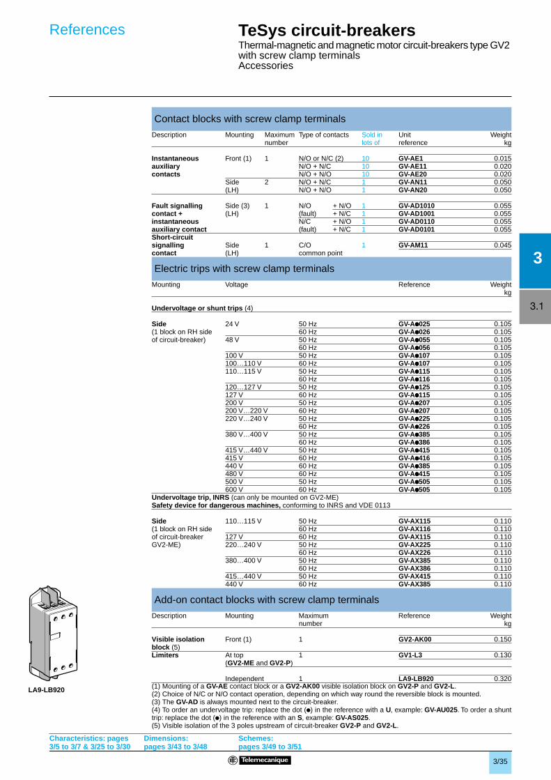
Contact blocks
Description Mounting Max. Type of contacts Sold in Unit Weightnumber lots of reference kg
Description Application Sold in Unit Weightlots of reference kg
Cable end For connection of 20 LA9-D99 –reducer (3) conductors from 1 to 1.5 mm2
(2) As % of Icu. g > 100 kA(3) 22 supplied with each circuit-breaker as standard.
References
GV2-MEpppppppp3
LA9-D99
Characteristics: pages3/5 to 3/7 & 3/25 to 3/30
Dimensions:pages 3/43 to 3/48
Schemes:pages 3/49 to 3/51
3/34
3
3.1
GV2-AK00GV1-L3
GV-AD
GV-AM11
GV-AM11
GV-AN
GV-AN
GV2-P
GV2-ME
GV-AX
GV-AU
GV-AS
GV-AE1
GV-AE1
GV-AE11, AE20
GV2-L
GV2-LE
3/35
3
3.1
TeSys circuit-breakersThermal-magnetic and magnetic motor circuit-breakers type GV2 with screw clamp terminalsAccessories
Undervoltage trip, INRS (can only be mounted on GV2-ME)Safety device for dangerous machines, conforming to INRS and VDE 0113
(1) Mounting of a GV-AE contact block or a GV2-AK00 visible isolation block on GV2-P and GV2-L.(2) Choice of N/C or N/O contact operation, depending on which way round the reversible block is mounted.(3) The GV-AD is always mounted next to the circuit-breaker.(4) To order an undervoltage trip: replace the dot (p) in the reference with a U, example: GV-AU025. To order a shunttrip: replace the dot (p) in the reference with an S, example: GV-AS025.(5) Visible isolation of the 3 poles upstream of circuit-breaker GV2-P and GV2-L.
Contact blocks with screw clamp terminals
Description Mounting Maximum Type of contacts Sold in Unit Weightnumber lots of reference kg
Side 24 V 50 Hz GV-Apppp025 0.105(1 block on RH side 60 Hz GV-Apppp026 0.105of circuit-breaker) 48 V 50 Hz GV-Apppp055 0.105
60 Hz GV-Apppp056 0.105100 V 50 Hz GV-Apppp107 0.105100…110 V 60 Hz GV-Apppp107 0.105110…115 V 50 Hz GV-Apppp115 0.105
60 Hz GV-Apppp116 0.105120…127 V 50 Hz GV-Apppp125 0.105127 V 60 Hz GV-Apppp115 0.105200 V 50 Hz GV-Apppp207 0.105200 V…220 V 60 Hz GV-Apppp207 0.105220 V…240 V 50 Hz GV-Apppp225 0.105
60 Hz GV-Apppp226 0.105380 V…400 V 50 Hz GV-Apppp385 0.105
60 Hz GV-Apppp386 0.105415 V…440 V 50 Hz GV-Apppp415 0.105415 V 60 Hz GV-Apppp416 0.105440 V 60 Hz GV-Apppp385 0.105480 V 60 Hz GV-Apppp415 0.105500 V 50 Hz GV-Apppp505 0.105600 V 60 Hz GV-Apppp505 0.105
Side 110…115 V 50 Hz GV-AX115 0.110(1 block on RH side 60 Hz GV-AX116 0.110of circuit-breaker 127 V 60 Hz GV-AX115 0.110GV2-ME) 220…240 V 50 Hz GV-AX225 0.110
60 Hz GV-AX226 0.110380…400 V 50 Hz GV-AX385 0.110
60 Hz GV-AX386 0.110415…440 V 50 Hz GV-AX415 0.110440 V 60 Hz GV-AX385 0.110
Add-on contact blocks with screw clamp terminals
Description Mounting Maximum Reference Weightnumber kg
Visible isolation Front (1) 1 GV2-AK00 0.150block (5)Limiters At top 1 GV1-L3 0.130
(GV2-ME and GV2-P)
Independent 1 LA9-LB920 0.320
References
Characteristics: pages3/5 to 3/7 & 3/25 to 3/30
Dimensions:pages 3/43 to 3/48
Schemes:pages 3/49 to 3/51
LA9-LB920
3/36
3
3.1
GV1-G09
GV2-G05
LA9-E07
GV2-AF3 GV2-AF4
LAD-31GV2-G454
GV2-AF01
GV2-AP0 2
LAD-31
O
TRIP.TRIP.
RESET
GV2-GA01
GV2-G454GV2-G254 GV2-G254
GV1-G10
GV1-G02
GK2-AF01
GV2-V03
GV2-AF02
3/37
3
3.1
TeSys circuit-breakersThermal-magnetic and magnetic motor circuit-breakers type GV2 with screw clamp terminalsAccessories
(1) Check with requirements of local Isolation standards before use.
Accessories
Description Application Sold in Unit Weightlots of reference kg
Adapter plate For mounting a GV2-ME 10 GV2-AF02 0.021or GV2-LE by screw fixingFor mounting a GV2-ME or 10 LAD-31 (supports GV2 only) 0.040GV2-P and contactor LC1-D09 to LAD-311(supports GV2 & contactor)D38 with front faces aligned
Height compensation plate 7.5 mm 10 GV1-F03 0.003
Combination block Between GV2 and contactor 10 GV2-AF01 0.020LC1-K or LP1-K Between GV2 and contactor 10 GV2-AF3 0.016LC1-D09…D38Between GV2 mounted 10 GV2-AF4 0.016on LAD-31 andcontactor LC1-D09…D38
Motor starter With 3-pole connection 1 GK2-AF01 0.120adapter plate for mounting a GV2 and
an LC1-D09 to D25 contactor Description Application Pitch Reference Weight
mm kg
Sets of 3-pole 2 tap-offs 45 GV2-G245 0.03663 A busbars 54 GV2-G254 0.038
72 GV2-G272 0.0423 tap-offs 45 GV2-G345 0.058
54 GV2-G354 0.0604 tap-offs 45 GV2-G445 0.077
54 GV2-G454 0.08572 GV2-G472 0.094
5 tap-offs 54 GV2-G554 0.100Description Application Sold in Unit Weight
lots of reference kg
Protective end cover (1) For unused busbar outlets 5 GV1-G10 0.005
Terminal blocks for Connection from the top 1 GV1-G09 0.040supply to one or more Can be fitted with current limiter 1 GV2-G05 0.115GV2-G busbar sets GV1-L3 (GV2-ME and GV2-P)
Cover for terminal block For mounting in 10 LA9-E07 0.005modular panels
Flexible 3-pole connection Centre distance between 10 GV1-G02 0.013for connecting a GV2 mounting rails: 100…120 mmto an LC1-D09…D25contactor
Set of connections For connecting GV2-ME 10 GV2-GA01 0.045upstream/downstream to a printed circuit board
Clip-in marker holders For GV2-P, GV2-L, GV2-LE 100 LA9-D92 (1) 0.001(supplied with each and GV2-RT (8 x 22 mm)circuit-breaker)
Padlockable external operator
Description Reference Weightkg
For GV2-P and GV2-L Padlocking in “On” and “Off” position GV2-AP01 0.200(150 to 290 mm) Black handle, blue legend plate, IP 54
Padlocking in “Off” position GV2-AP02 0.200Red handle, yellow legend plate, IP 54
For GV2-LE Padlocking in “On” and “Off” position GV2-AP03 0.280Black handle, blue legend plate, IP 54
Padlocking device
For all GV2 devices For use with up to 6 padlocks (not supplied), GV2-V03 0.130Ø 6 mm shank max.
References
Dimensions:pages 3/43 to 3/48
3/38
3
3.1
GV2-MC
GV2-SN
GV2-E01
GV2-K011
GV2-V01
GV2-MP
GV2-CP
GV2-K04
3/39
3
3.1
TeSys circuit-breakersEnclosed thermal-magnetic motor circuit-breakerstype GV2-ME and accessories, assembled by user
Thermal-magnetic motor circuit-breakers and accessories: see pages 3/31 and 3/33.The motor starter comprising an enclosed motor circuit-breaker GV2-ME conforms to IEC/EN 60947-4-1.
Ithe
(1) The GV2-MCK04 enclosure has a GV2-K04 mushroom head Stop pushbutton fitted as standard.(2) Supplied with IP 55 sealing kit. For use with GV2-Mp01.(3) Padlockable in “Off” position using Ø 4 to 8 mm shank padlocks.
Enclosed thermal-magnetic motor circuit-breakers GV2-ME
Enclosures for thermal-magnetic motor circuit-breakers GV2-ME
Type Degree of protection Possible attachments Reference Weighton side of GV2-MELeft Right kg
Surface IP 41 1 1 GV2-MC01 0.290mounting Double,insulated with IP 55 1 1 GV2-MC02 0.300protective or GV2-MCK04 (1) 0.420conductor.Sealable IP 55 for 1 1 GV2-MC03 0.300cover temperature < + 5 ˚C
Flush, IP 41 (front face) 1 1 GV2-MP01 0.115mounting IP 41 (reduced flush mounting) – 1 GV2-MP03 0.115with protective IP 55 (front face) 1 1 GV2-MP02 0.130conductor IP 55 (reduced flush mounting) – 1 GV2-MP04 0.130
Front plate
For direct control, through a panel IP 55 GV2-CP21 0.800of a chassis-mounted GV2-ME
Accessories common to all enclosures (to be ordered separately)
Description Sold in Unit Weightlots of reference kg
Padlocking device (2) 1 to 3 padlocks 1 GV2-V01 0.075for GV2-ME operator (padlocking is only Ø 4 to 8 mmpossible in “O” position)
Mushroom Spring return (2) 1 GV2-K011 0.052head “Stop” Latching (2) Key release 1 GV2-K021 0.160pushbutton IP 55 key n˚ 455Ø 40 mm,red Turn to 1 GV2-K031 0.115
release 1 GV2-K04 (3) 0.120
Sealing kit For enclosures IP 55 10 GV2-E01 0.012and front plate IP 55
for θ < + 5 ˚C 10 GV2-E02 0.012
Neutral terminal 100 AB1-VV635UBL 0.015
Partition 50 AB1-AC6BL 0.003Description Voltage Colour Sold in Unit Weight
V lots of reference kg
Neon 110 Green 10 GV2-SN13 0.019indicator Red 10 GV2-SN14 0.019light Orange 10 GV2-SN15 0.019
Clear 10 GV2-SN17 0.019220/240 Green 10 GV2-SN23 0.019
Red 10 GV2-SN24 0,019Orange 10 GV2-SN25 0,019Clear 10 GV2-SN27 0,019
Magnetic circuit-breakers GV2-L with screw clamp terminals
Rotary handleStandard power ratings Magnetic Trip- Use in Reference Weightof 3-phase motors protection ping association50/60 Hz in category AC-3 rating current with 400/415 V 500 V 690 V Id ± 20 % thermalP Icu Ics P Icu Ics P Icu Ics overload
(1) (1) (1) relaykW kA kW kA kW kA A A kg
0.09 g g – – – – – – 0.4 5 LRD-03 GV2-L03 0.330
0.12 g g – – – 0.37 g g 0.63 8 LRD-04 GV2-L04 0.330
0.18 g g – – – – – – 0.63 8 LRD-04 GV2-L04 0.330
– – – – – – 0.55 g g 1 13 LRD-05 GV2-L05 0.330
0.25 g g – – – – – – 1 13 LRD-05 GV2-L05 0.330
– – – – – – 0.75 g g 1 13 LRD-06 GV2-L05 0.330
0.37 g g 0.37 g g – – – 1 13 LRD-05 GV2-L05 0.330
0.55 g g 0.55 LRD-06 GV2-L06 0.330
– – – 0.75 g g – – – 1.6 22.5 LRD-06 GV2-L06 0.330
0.75 g g 1.1 g g 1.5 4 100 2.5 33.5 LRD-07 GV2-L07 0.330
1.1 g g – – – – – – 2.5 33.5 LRD-08 GV2-L08 0.330
1.5 g g 1.5 g g 3 4 100 51 LRD-08 GV2-L08 0.330
– – – 2.2 g g – – – 4 51 LRD-08 GV2-L08 0.330
2.2 g g 3 g g 4 4 100 6.3 78 LRD-10 GV2-L10 0.330
3 g g 4 10 100 5.5 4 100 10 138 LRD-12 GV2-L14 0.330
4 g g 5.5 10 100 – – – 10 138 LRD-14 GV2-L14 0.330
References TeSys circuit-breakersMagnetic motor circuit-breakerstypes GV2-L and GV2-LE
Characteristics: pages 3/5 to 3/7 & 3/25 to 3/30
Dimensions:pages 3/43 to 3/48
Schemes:pages 3/49 to 3/51
GV2-L
3/41
3
3.1
(1) As % of Icu. TeSys protection components
Magnetic circuit-breakers GV2-LE with screw clamp terminals
Rocker leverStandard power ratings Magnetic Trip- Use in Reference Weightof 3-phase motors protection ping association50/60 Hz in category AC-3 rating current with 400/415 V 500 V 690 V Id ± 20 % thermalP Icu Ics P Icu Ics P Icu Ics overload
(1) (1) (1) relaykW kA kW kA kW kA A A kg
0.06 g g – – – – – – 0.4 5 LR2-K0302 GV2-LE03 0.330
0.09 g g – – – – – – 0.4 5 LR2-K0304 GV2-LE03 0.330
0.12 g g – – – 0.37 g g 0.63 8 LR2-K0304 GV2-LE04 0.330
0.18 g g – – – – – – 0.63 8 LR2-K0305 GV2-LE04 0.330
– – – – – – 0.55 g g 1 13 LR2-K0305 GV2-LE05 0.330
0.25 g g – – – – – – 1 13 LR2-K0306 GV2-LE05 0.330
– – – – – – 0.75 g g 1 13 LR2-K0306 GV2-LE05 0.330
0.37 g g 0.37 g g – – – 1 13 LR2-K0306 GV2-LE05 0.330
0.55 g g 0.55 g g 1.1 g g 1.6 22.5 LR2-K0307 GV2-LE06 0.330
– – – 0.75 g g – – – 1.6 22.5 LR2-K0307 GV2-LE06 0.330
0.75 g g 1.1 g g 1.5 3 75 2.5 33.5 LR2-K0308 GV2-LE07 0.330
1.1 g g – – – – – – 2.5 33.5 LR2-K0308 GV2-LE08 0.330
1.5 g g 1.5 g g 3 3 75 4 51 LR2-K0310 GV2-LE08 0.330
– – – 2.2 g g – – – 4 51 LR2-K0312 GV2-LE08 0.330
2.2 g g 3 50 100 4 3 75 6.3 78 LR2-K0312 GV2-LE10 0.330
3 g g 4 10 100 5.5 3 75 10 138 LR2-K0314 GV2-LE14 0.330
4 g g 5.5 10 100 – – – 10 138 LR2-K0316 GV2-LE14 0.330
TeSys circuit-breakersMagnetic motor circuit-breakerstypes GV2-L and GV2-LE
References
Characteristics: pages 3/5 to 3/7 & 3/25 to 3/30
Dimensions:pages 3/43 to 3/48
Schemes:pages 3/49 to 3/51
GV2-LE
3/42
3
3.1
TeSys circuit-breakersThermal magnetic circuit-breakerstype GV2-RT (1)
Control by rocker lever
Control by rocker lever
(1) Characteristics of GV2-RT identical to those of GV2-ME except for tripping current (id).(2) Other accessories such as mounting, cabling and marking accessories are identical to those used for GV2-MEmotor circuit-breakers, see page 3/39.
For motors with high current peak on starting
Standard power ratings Setting Magnetic Reference Weightof 3-phase motors range of tripping50/60 Hz in category AC-3 thermal current220 400 trips Id ± 20 %230 V 415 V 440 V 500 V 690 VkW kW kW kW kW A A kg
Standard power ratings Setting range Magnetic Reference Weight230 400 of thermal tripping current240 V 415 V 440 V 500 V 690 V trips Id ± 20 %kVA kVA kVA kVA kVA A A kg
TeSys circuit-breakersThermal-magnetic motor circuit-breakerstypes GV2-ME and GV2-P
c = 86 on AM1-DE200, ED200 (35 x 15)
GV2-ME GV-AX GV-AD, AM, AN, AU, AS, AX GV-AE
bGV2-MEpp 89GV2-MEpp3 101
(1) MaximumX1 Electrical clearance = 40 mm for Ue ≤ 690 VGV2-P GV-AD, AM, AN, AU, AS GV2-AK00
(1) MaximumX2 = 40 mmX1 Electrical clearance = 40 mm for Ue ≤ 415 V, or 80 mm for Ue = 440 V, or 120 mm for Ue = 500 and 690 VMounting GV2-MEOn 35 mm 6 rail On panel with adapter plate GV2-AF02 On pre-slotted mounting plate On mounting rail DZ5-MB201c = 78.5 on AM1-DP200 (35 x 7.5) AM1-PA
Mounting GV2-POn mounting rail AM1-DE200, On panel On pre-slotted Plate GK2-AF01ED200 (35 x 15) mounting plate AM1-PA
Dimensions,mounting
Block GV-AD, AM, ANBlock GV-AU, AS, AX
Characteristics: pages 3/5 to 3/7 & 3/25 to 3/30
References:pages 3/31 to 3/42
Schemes:pages 3/49 to 3/51
Block GV-AD, AM, AN
Block GV-AU, AS
3/44
3
3.1
39
3513
1,5...5
7
53 135…284
65
5,2
= =
54
= =
==
54
45
129
44,5
89
77
X1
X1
40
79 45
152
c1
c
45
b
45
b
c1
c
d
d1
c1
c
d1
d
45
b
45
b
c1
c
TeSys circuit-breakersThermal-magnetic motor circuit-breakerstypes GV2-ME and GV2-P
Mounting of external operator GV2-AP01 or GV2-AP02 for GV2-P
GV2-AF01 GV2-AF3Combination GV2-ME + K contactor Combination GV2-ME + model d contactor Combination GV2-P + model d contactor
GV2-ME + LC1-D09…D18 LC1-D25 and D32 GV2-P + LC1-D09…D18 LC1-D25 & D32b 176.4 186.8 b 177.4 187.8c1 88.65 94.95 c1 88.6 94.95c 94.15 100.45 c 94.1 100.45
d1 91 91d 96.8 96.8
GV2-AF4 + LAD-31 GV2-ME + GV1-L3 (current limiter)Combination GV2-ME + model d contactor Combination GV2-P + model d contactor
X1 = 10 mm for Ue = 230 V or 30 mm for 230 V < Ue ≤ 690 V
7.5 mm height compensation plateGV1-F03
GV2-ME + LC2-D09…D18 LC2-D25 and D32 GV2-P + LC2-D09…D18 LC2-D25 and D32b 188.6 199 b 169.1 199.5c1 92.7 99 c1 116.8 116.8c 98.2 104.5 c 122.3 122.3d1 98.3 98.3d 103.8 103.8
Door drilling
Dimensions,mounting (continued)
Characteristics: pages 3/5 to 3/7 & 3/25 to 3/30
References:pages 3/31 to 3/42
Schemes:pages 3/49 to 3/51
3
3.1
3/45
147
84
(1) 2xØ5,3x6,3
93 =
130
==
=
1...6
a112
140
=12
7= = 93,5 =
106,5
71
93
6,5
117
133
a= =
9,5
1...4
12
76
93
7,5
118
21
133
= =
6211
,5
2 x Ø3,3Ø17
Front plate GV2-CP21For GV2-ME
Surface mounting enclosure GV2-MC0iFor GV2-ME
(1) 4 knock-outs for 16 mm plastic cable glands or n° 16 conduit
TeSys circuit-breakersThermal-magnetic motor circuit-breakerstype GV2-ME
Dimensions,mounting
3/46
3
3.1
44,5
89
82
X1
5026
X2
15
6145
==
c
44,5
44,5
84,5
4,2
35
50/6
0
AF1-EA4
35
50/6
0
15 35
50 60
DZ5-MB201
GV2-AF02
DZ5-ME8
44
89
167,5
6612,5
X1
X1 44,5
45=
=
15
10
9814
44,5
32
13,5
84
44,5
44,5
106
AF1-EA4
84
13,5
39
3513
9,3 9,3 18
81 (1)
24
5545
135
9,5
45
35
54
35
5
9,3 9,3
81 (1)
1818
TeSys circuit-breakersMagnetic motor circuit-breakerstypes GV2-L and GV2-LE
Dimensions,mounting
Block GV-AD, AM, AN
Block GV-AU, AS
Block GV-AD, AM, ANBlock GV-AU, AS
Characteristics: pages3/5 to 3/7 & 3/25 to 3/30
References:pages 3/31 to 3/42
Schemes:pages 3/49 to 3/51
or 80 mm for Ue = 440 V,
7.5 mm height compensation plateGV1-F03
c = 80 on AM1-DP200 (35 x 7.5)c = 88 on AM1-DE200, ED200 (35 x 15)
GV2-L GV-AD, AM, AN, AU, AS GV2-AK00
X1 Electrical clearance = 40 mm for Ue ≤ 415 V, (1) Maximum.
or 120 mm for Ue = 500 and 690 V.X2 = 40 mm.Mounting of GV2-L Adaptor plate GK2-AF01On mounting rail AM1-DE200, On panel On pre-slotted mounting plateAM1-ED200 (35 x 15) AM1-PA
GV2-LE GV-AD, AM, AN, AU, AS GV-AE
X1 Electrical clearance = 40 mm for Ue ≤ 690 V. (1) Maximum.Mounting of GV2-LEOn 35 mm 7 rail On panel with adaptor plate GV2-AF02 On pre-slotted mounting On mounting rails DZ5-MB201
plate AM1-PA
3/47
3
3.1
54
= =
==
54
4xØ3,5 Ø43
1,5...5
13
53 133…282
65
6 = =
12,3
5,2
= =
1,5...5
7
53 6135…284
65
Mounting of external operator GV2-AP01 or GV2-AP02 for GV2-L
Mounting of external operator GV2-AP03 for GV2-LE
Door cut-out
TeSys circuit-breakersMagnetic motor circuit-breakers types GV2-L and GV2-LE
Dimensions,mounting
Characteristics: pages3/5 to 3/7 & 3/25 to 3/30
References:pages 3/31 to 3/42
Schemes:pages 3/49 to 3/51
3/48
3
3.1
l
GV1-G09
30
260
89
66
X1
44167,5
X1
12,5
45=
=
44,5 1,5...5
13
53 133…282
65
6 = =
12,3
AF1-EA4
35
50/6
0
35
6050
1515
DZ5-MB201
GV2-AF02
DZ5-ME8
50/6
0
4,2
35c
44,5
44,5
84,5
63
l3
a
18
p
45
l
Sets of busbars GV2-G445, GV2-G454, GV2-G472, with terminal block GV2-G05
with terminal block GV1-G09
Mounting of GV2-RT
l pGV2-G445 (4 x 45 mm) 179 45GV2-G454 (4 x 54 mm) 206 54GV2-G472 (4 x 72 mm) 260 72
Sets of busbars GV2-Gppp Sets of busbars GV2-G245, GV2-G254, GV2-G272
lGV2-G245 (2 x 45 mm) 89GV2-G254 (2 x 54 mm) 98GV2-G272 (2 x 72 mm) 116
Set of busbars GV2-G554 Sets of busbars GV2-G345 and G354
lGV2-G345 (3 x 45 mm) 134GV2-G354 (3 x 54 mm) 152
Dimensions of GV2-RT Mounting of external operator GV2-AP03
X1: Electrical clearance = 40 mm for Ue < 690 V
on 35 mm 7 rail On panel with adapter On pre-slotted On mounting rails DZ5-MBc = 80 on AM1-DP200 (35 x 7.5) plate GV2-AF02 mounting plate AM1-PAc = 88 on AM1-DE200, ED200 (35 x 15)
Dimensions,mounting (continued)
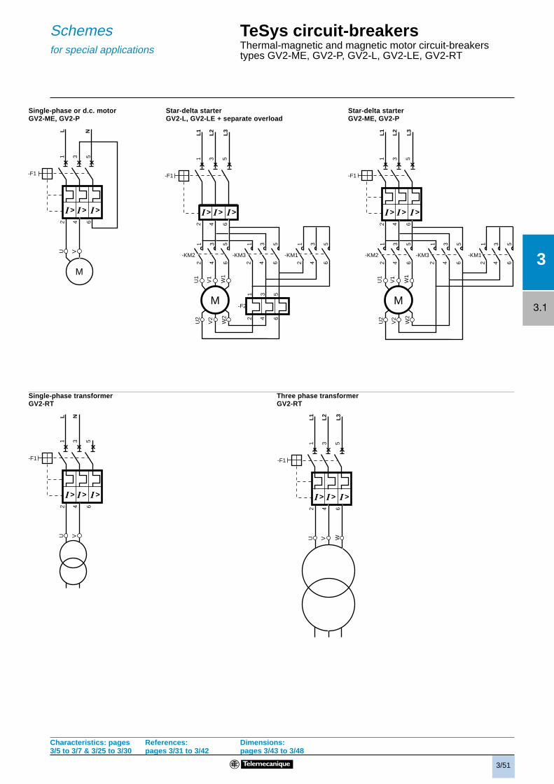
TeSys circuit-breakersThermal-magnetic motor circuit-breakerstypes GV2-ME, GV2-P, GV2-L, GV2-LE, GV2-RT
Characteristics: pages3/5 to 3/7 & 3/25 to 3/30
References:pages 3/31 to 3/42
Schemes:pages 3/49 to 3/51
3/49
3
3.1
2/T
1
4/T
2
6/T
3
1/L1
3/L2
5/L3
2/T
1
4/T
2
6/T
3
1/L1
3/L2
5/L3
1/L1
3/L2
5/L3
1314 12
11 1314 22
21 1314
2324
9798
535452
51
969553
549695 97
98
5152
(62) 32
(61) 31 43 (73)
44 (74)
(64) 34
(63) 33 43 (73)
44 (74) 05
0608
D1
D2
C1
C2
D1
D2
E1
E2
2/T
1
4/T
2
6/T
3
1/L1
3/L2
5/L3
D1
D2
E2
E1
Schemes
or
TeSys circuit-breakersThermal-magnetic motor circuit-breakerstypes GV2-ME, GV2-P and GV2-RT
Side mounting add-on contact blocksInstantaneous auxiliary contacts and fault signalling contacts
Voltage trips
GV2-MEpp and GV2-RT GV2-Ppp
Current limiter GV1-L3 Front mounting add-on contact blocksInstantaneous auxiliary contactsGV-AE1 GV-AE11 GV-AE20
Use of fault signalling contact and Connection of undervoltage trip for dangerous machinesshort-circuit signalling contact (conforming to INRS) on GV2-ME only
Tripsignalling
Short-circuitsignalling
GV-AM11 GV-AD10pp
N/C or N/O Start-Stop contact
Characteristics: pages3/5 to 3/7 & 3/25 to 3/30
References:pages 3/31 to 3/42
Dimensions:pages 3/43 to 3/48
10 Agl max
3/50
3
3.1
1314 12
11 1314 22
21 1314
2324
(62) 32
(61) 31 43 (73)
44 (74)
(64) 34
(63) 33 43 (73)
44 (74)
050608
D1
D2
C1
C2
9798
535452
51
969553
549695 97
98
5152
2/T
1
4/T
2
6/T
3
1/L1
3/L2
5/L3
2/T
1
4/T
2
6/T
3
1/L1
3/L2
5/L3
TeSys circuit-breakersMagnetic motor circuit-breakers types GV2-L and GV2-LE
Front mounting add-on contact blocksInstantaneous auxiliary contacts
Side mounting add-on contact blocksInstantaneous auxiliary contacts and fault signalling contacts