38
Roy Harter RLH Global Services [email protected] SAMG-D course, IAEA, Vienna, Austria 19 -23 October 2015 FLEX Implementation

Roy Harter RLH Global Services
SAMG-D course, IAEA, Vienna, Austria
19 -23 October 2015
FLEX Implementation

2
What is FLEX?
• US Nuclear Industry Response to NRC Mitigating Strategies Order EA 12-049, “Order Modifying Licenses with Regard to Requirements for Mitigation Strategies for Beyond-Design-Basis External Events”
• Approach is outlined in NEI 12-06, Rev 1 • Provides a diverse and flexible means to prevent fuel
damage while maintaining containment function in beyond design basis external event conditions resulting in an: • Extended Loss of AC Power, and • Loss of Normal Access to the Ultimate Heat Sink
• Objective: • Establish an essentially indefinite coping capability by
relying upon installed equipment, onsite portable equipment, and pre-staged offsite resources
2

3
FLEX Objectives

4
Diverse & Flexible Coping Capability (FLEX)
Protection of Plant Equipment
Prevention of Fuel Damage
Design Basis External Events
SBO Coping Capability
SAMGs
Emergency Plans
Design Basis External Events
SBO Coping Capability
SAMGs
Emergency Plans
Increased Defense-in-
Depth
Diverse & Flexible CopingStrategy
(FLEX)
Emergency Response
Current Current plus FLEX

5
FLEX Addresses NRC Tier 1 Recommendations

6
FLEX Elements
• Both plant and FLEX equipment that provides means of obtaining power and water to maintain or restore key safety functions for all reactors at a site.
– This could include equipment such as pumps, generators, batteries and battery chargers, compressors, hoses, couplings, tools, debris clearing equipment, temporary flood protection equipment and other supporting equipment or tools.
• Reasonable staging and protection of FLEX equipment from BDBEEs applicable to a site.
–The FLEX equipment would be reasonably protected from applicable site-specific severe external events to provide reasonable assurance that N sets of FLEX equipment will remain deployable following such an event.

7
FLEX Elements
• Procedures and guidance to implement FLEX strategies. – FLEX Support Guidelines (FSG), to the extent possible, will
provide pre-planned FLEX strategies for accomplishing specific tasks in support of Emergency Operating Procedures (EOP) and Abnormal Operating Procedures (AOP) functions to improve the capability to cope with beyond-design-basis external events.
• Programmatic controls that assure the continued viability and reliability of the FLEX strategies.
– These controls would establish standards for quality, maintenance, testing of FLEX equipment, configuration management and periodic training of personnel.

8
FLEX Analysis
• Plant-specific analyses will determine the duration of each phase.
– Recovery of the damaged plant is beyond the scope of FLEX capabilities as the specific actions and capabilities will be a function of the specific condition of the plant and these conditions cannot be known in advance.
• To the extent practical, generic thermal hydraulic analyses will be developed to support plant-specific decision-making.
– Justification for the duration of each phase will address the on-site availability of equipment, the resources necessary to deploy the equipment consistent with the required timeline, anticipated site conditions following the beyond-design-basis external event, and the ability of the local infrastructure to enable delivery of equipment and resources from off-site.

9
Use MAAP to Identify Capabilities for Extended and Phase 1-2 Transition

10
Use MAAP to Identify Capabilities for Extended and Phase 1-2 Transition
1 2 3 4 5 6 7 8 9 10 11 12 13 14 15 16 17 18 19 20 21 22 23 24t
(Hours)
Toru
s wat
er te
mpe
ratu
re ex
ceed
s 260
° F
Cont
ainm
ent V
ent @
PCP
L
PSP
Exce
eded
Core
Dam
age
RPV
level
belo
w TAF
Toru
s wat
er te
mpe
ratu
re ex
ceed
s 230
° F
Toru
s wat
er te
mpe
ratu
re ex
ceed
s 200
° F
HCL E
xcee
ded;
Dep
ress
urize
RPV
to <5
0 ps
ig; R
CIC
Trip
ped
SRV
Depr
essu
rize t
o 15
0 ps
ig
SBO
with R
CIC
Oper
atin
g (To
rus S
uctio
n; R
ecirc
Seal
Leak
36
gpm
)
Aggressive Cooldown to 150 psig
at <100° F/hr
Result: Adequate Core Cooling 6.0 Hours

11
1 2 3 4 5 6 7 8 9 10 11 12 13 14 15 16 17 18 19 20 21 22 23 24t
(Hours)
Toru
s wat
er te
mpe
ratu
re e
xcee
ds 2
60° F
Cont
ainm
ent V
ent @
PCP
L
PSP
Exce
eded
All A
lignm
ents
of P
orta
ble
D/G
to B
atte
ry C
harg
ers &
Por
tabl
e Di
esel
Fire
Pum
p Co
mpl
eted
Toru
s wat
er te
mpe
ratu
re e
xcee
ds 2
30° F
HCL E
xcee
ded
SRV
Depr
essu
rize
to 1
50 p
sig
SBO
with
RCI
C Op
erat
ing
(Tor
us S
uctio
n; R
ecirc
Sea
l Lea
k 36
gpm
)
Aggressive Cooldown to 150 psig
at <100° F/hr
Result: Adequate Core Cooling >24 HoursRCIC operable for 6.2 hoursDC battery life extended to 7 hours based on load shedPortable equipment aligned by 6.2 hours
Toru
s wat
er te
mpe
ratu
re e
xcee
ds 2
00° F
Use MAAP to Identify Capabilities for Extended and Phase 1-2 Transition

12
FLEX Boundary Conditions
• Beyond-design-basis external event occurs impacting all units at site.
• All reactors on-site initially operating at power, unless site has procedural direction to shut down due to the impending event.
• Each reactor is successfully shut down when required (i.e., all rods inserted, no ATWS).
• On-site staff is at site administrative minimum shift staffing levels.
• No independent, concurrent events, e.g., no active security threat.
• All personnel on-site are available to support site response.
• Spent fuel in dry storage is outside the scope of FLEX.

13
Site Staffing Challenges
• On-shift personnel resource planning is limited to the minimum complement described in the site Emergency Plan.
• This staffing level is the minimum on-shift complement, such as present during a backshift, weekend or holiday.
• Sites are to perform staffing assessments to include the consideration that the on-shift personnel assigned emergency plan implementation functions are not assigned responsibilities that would prevent the timely performance of their assigned functions as specified in the emergency plan.
• The staffing assessment should also consider the applicable actions from the Station Blackout (SBO) coping strategies.

14
Site Access Challenges (NEI-12-01)
• First 6 hours – No site access. This duration reflects the time necessary to clear roadway obstructions, use different travel routes, mobilize alternate transportation capabilities (e.g., private resource providers or public sector support), etc.
• 6-24 hours – Limited site access. Individuals may access the site by walking, personal vehicle or via alternate transportation capabilities (e.g., private resource providers or public sector support).
• 24+ hours – Improved site access. Site access is restored to a near-normal status and/or augmented transportation resources are available to deliver equipment, supplies and large numbers of personnel.

15
FLEX Assessment Process

16
FLEX Assessment Process

17
BWR Baseline Coping Summary

18
PWR Baseline Coping Summary

19
Establishing Event Response Sequence

20
Establishing Event Response Sequence

21
Instrumentation Assessment
• Actions specified in plant procedures/guidance for loss of ac power are predicated on use of instrumentation and controls powered by station batteries. In order to extend battery life, a minimum set of parameters necessary to support strategy implementation should be defined. The parameters selected must be able to demonstrate the success of the strategies at maintaining the key safety functions as well as indicate imminent or actual core damage to facilitate a decision to manage the response to the event within the Emergency Operating Procedures and FLEX Support Guidelines or within the SAMGs. Typically, these parameters would include the following:

22
FLEX Mitigation Strategies
• FLEX employs a three phase approach: Phase 1 - Initially cope by relying on installed plant
equipment, Phase 2 - Transition from installed plant equipment
to onsite FLEX equipment, Phase 3 - Obtain additional capability and
redundancy from offsite equipment until power, water, and coolant injection systems are restored or commissioned.
• Diverse and flexible to enable deployment of the strategies for a range of initiating events and plant conditions

23
Representative High-level Example (BWR)
1. Phase 1 Initial Coping Capability – Use RCIC for RPV makeup from suppression pool – Rely on DC Power for key instrumentation and
controls 2. Phase 2 Extended Coping Capability
– Charge battery to maintain DC power – Use Reliable Hardened Vent for containment heat
removal – Provide extended RPV makeup with portable pump 1. Phase 3 Extended Coping Capability – Use additional offsite equipment from Regional
Response Center

24
Representative High-level Example (PWR)
• Phase 1 Initial Coping Capability – Turbine-driven AFW for SG makeup from Condensate
Storage Tank – Rely on DC Power for key instrumentation and
controls • Phase 2 Extended Coping Capability
– Charge battery to maintain DC power – Provide extended SG makeup with portable pump – Provide RCS makeup with portable pump, as needed
• Phase 3 Extended Coping Capability – Use additional offsite equipment from Regional
Response Center

25
FLEX Communications Assessment
• Guidance provided in NEI 12-01, Section 4 – Phase 1 – assess capabilities for all specified EP functions
except FLEX – Phase 2 – assess capabilities for FLEX
• Should have methods and capabilities necessary to support simultaneous implementation of any 2 FLEX strategies for each affected unit

SAFER (Phase 3) Organization and Response Plan

27
SAFER Organization
SAFER – Strategic Alliance for FLEX Emergency Response • SAFER is an alliance established between AREVA and Pooled
Inventory Management (PIM).
• The SAFER team is contracted by the nuclear industry to establish and operate National SAFER Response Centers (NSRCs) to purchase, store, maintain and deliver emergency response equipment in the case of a major nuclear accident or BDBEE in the US.
• An effective response is dependent on integrated planning and response actions among the nuclear station, SAFER team, governmental authorities and industry & vendor support personnel.

28
SAFER Facilities
• Primary and Alternate Facilities – Two Facilities in Case One is Rendered Out of Service by an Event – SAFER Control Centers & National SAFER Response Centers

29
SAFER Facilities
• National SAFER Response Centers (NSRC) – Storage and Deployment of Equipment up to 4 Units – Duplicate Equipment at Each Response Center – Preventive Maintenance and Testing Performed at NSRCs
• Two Locations – Memphis, TN – Phoenix, AZ
• Staffing
– NSRC is Manned to Perform Maintenance / Testing – Activated by the SAFER Control Center (SCC) to Support
Deployment

30
Staging Areas (Selected by the site)

31
Staging Areas
• Staging Areas Staging Areas Are Determined by the Utility (illustrated in the next slide) Staging Area ‘A’ Final Resting (Operational) Place(s) of equipment on-site
Staging Area ‘B’ Staging Area on-site (preferred if NSRC trucks can directly access the site)
Staging Area ‘C’ Primary off-site Staging Area ~= 25 Miles From the Site
Staging Area ‘D’ Optional Off-site Staging Area ~= 25 Miles From the Site

32
SAFER Staging Area Sizing Study (~360’ x 250’)
The helicopter area may be preferred to be a safe distance from personnel or staging area operations

33
Equipment - Generic
Equipment Performance Characteristics # of Units
Medium Voltage Generator 4160 V 1 MW 18 Low Voltage Generator 480 V 1100 kW 10
High Pressure Injection Pump 2000 psi 60 gpm 10 SG/RPV Makeup Pump 500 psi 500 gpm 10 Low Pressure / Medium Flow Pump 300 psi 2500 gpm 10
Low Pressure / High Flow Pump 150 psi 5000 gpm 10
Lighting Towers 440,000 lumens
(minimum) 30
Diesel Fuel Transfer 500 gallon air-lift container 10 Diesel Fuel Transfer Tank 264 gallon tank, with mounted
AC/DC pumps 10
Portable Fuel Transfer Pump 60 gpm after filtration 10
34
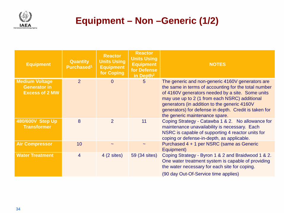
Equipment – Non –Generic (1/2)
Equipment Quantity Purchased1
Reactor Units Using Equipment for Coping
Reactor Units Using Equipment for Defense
in Depth2
NOTES
Medium Voltage Generator in Excess of 2 MW
2 0 5 The generic and non-generic 4160V generators are the same in terms of accounting for the total number of 4160V generators needed by a site. Some units may use up to 2 (1 from each NSRC) additional generators (in addition to the generic 4160V generators) for defense in depth. Credit is taken for the generic maintenance spare.
480/600V Step Up Transformer
8 2 11 Coping Strategy - Catawba 1 & 2. No allowance for maintenance unavailability is necessary. Each NSRC is capable of supporting 4 reactor units for coping or defense-in-depth, as applicable.
Air Compressor 10 ~ ~ Purchased 4 + 1 per NSRC (same as Generic Equipment)
Water Treatment 4 4 (2 sites) 59 (34 sites) Coping Strategy - Byron 1 & 2 and Braidwood 1 & 2. One water treatment system is capable of providing the water necessary for each site for coping. (90 day Out-Of-Service time applies)

35
Equipment – Non –Generic (2/2)
Equipment Quantity Purchased1
Reactor Units Using Equipment for Coping
Reactor Units Using Equipment for Defense
in Depth2
NOTES
Portable Submersible Pump
4 0 10 Initially thought to be required for some, this equipment was procured and only a small amount retained (2 at each NSRC) for defense-in-depth.
Water Storage 16 0 28 No allowance for maintenance unavailability is necessary because maintenance is limited to visual inspection for age-related degradation. Each NSRC is capable of supporting 4 reactor units as defense-in-depth.
Mobile Boration System
10 ~ ~ Purchased 4 + 1 per NSRC (same as Generic Equipment)
Ventilation Fan 10 ~ ~ Purchased 4 + 1 per NSRC (same as Generic Equipment)
Suction Lift Booster Pump
14 ~ ~ A 2 reactor unit site utilizes 3 booster pumps (5000 gpm each): 1 booster pump per 5000 gpm generic pump (2) and shares a single booster pump between both 2500 gpm generic pumps. 2 sites utilize 6 + 1 spare per NSRC.

36
SAFER Response Plans
Site-Specific SAFER Response Plan Chapters 1.Introduction 2.SAFER Control Center 3.National SAFER Response Center 4.Logistics & Transportation 5.Staging Area 6.Site Interface Procedure 7.Equipment Listing Addendum A – SAFER Contact list Addendum B – Vendor Contact list Addendum C – State Contact List Addendum D – Event Log Form

37
Defense-In-Depth for Extreme External Events

38
Defense-In-Depth for Extreme External Events


