Fluid Power Conference & Expo Fluid Power Conference & Expo Summer 2012 St. Paul, Minnesota Summer 2012 St. Paul, Minnesota Introduction to Proportional Valve Controllers June 26-27, 2012 Presenter: Steve Wilson President, WhiteOak Controls 1
Transcript
Fluid Power Conference & ExpoFluid Power Conference & ExpoSummer 2012 St. Paul, MinnesotaSummer 2012 St. Paul, Minnesota
Introduction to Proportional Valve ControllersJune 26-27, 2012
Presenter:Steve Wilson
President, WhiteOak Controls
1
Fluid Power Conference & ExpoFluid Power Conference & ExpoSummer 2012 St. Paul, MinnesotaSummer 2012 St. Paul, Minnesota
BSEE electrical and computer engineeringWorked as Design Engineer for consumer electronics company for 2 yearsWorked as Automation Engineer for equipment manufacturer for 11 yearsDeveloped proportional controlsStarted WhiteOak Controls in 1999Design and Manufacture innovative control solutions for fluid power marketsBased in Mediapolis, Iowa
2
Fluid Power Conference & ExpoFluid Power Conference & ExpoSummer 2012 St. Paul, MinnesotaSummer 2012 St. Paul, Minnesota
Discussion OutlineDiscussion OutlineElectro-hydraulic proportional valve system overview
Role of the controllerWhy is controller neededHow does it workCommon setup parametersTypical setup procedure
Other types of controllersClosed loopSpecial function
3
Fluid Power Conference & ExpoFluid Power Conference & ExpoSummer 2012 St. Paul, MinnesotaSummer 2012 St. Paul, Minnesota
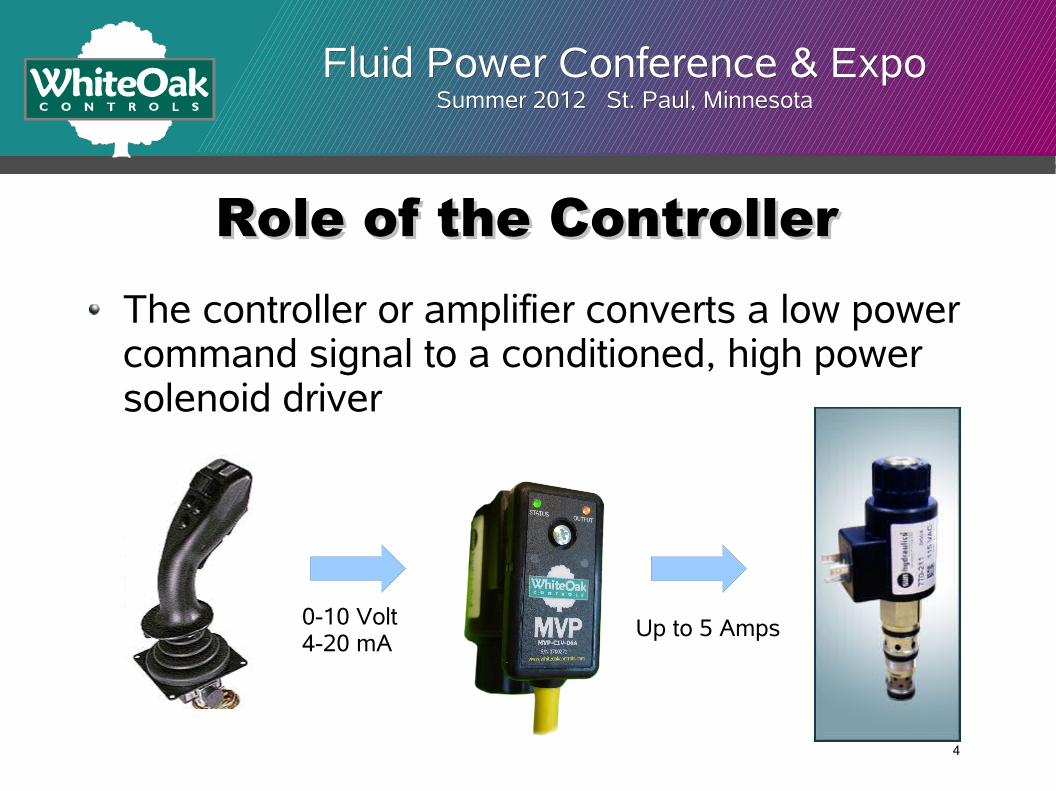
Role of the ControllerRole of the ControllerThe controller or amplifier converts a low power command signal to a conditioned, high power solenoid driver
0-10 Volt4-20 mA Up to 5 Amps
4
Fluid Power Conference & ExpoFluid Power Conference & ExpoSummer 2012 St. Paul, MinnesotaSummer 2012 St. Paul, Minnesota
Why do I need a controller?Why do I need a controller?To amplify the signalTo monitor and maintain the current as the resistance changesTo provide ditherTo incorporate other features such as rampingTo provide fault monitoring
5
Fluid Power Conference & ExpoFluid Power Conference & ExpoSummer 2012 St. Paul, MinnesotaSummer 2012 St. Paul, Minnesota
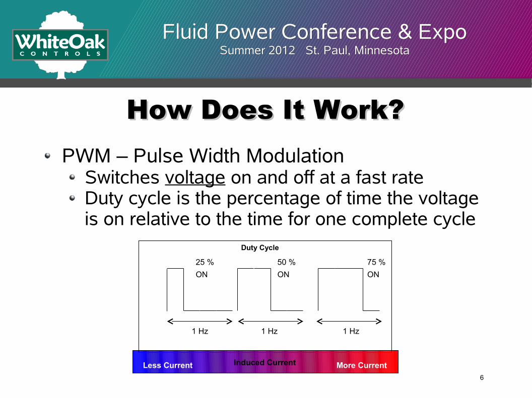
How Does It Work?How Does It Work?PWM – Pulse Width Modulation
Switches voltage on and off at a fast rateDuty cycle is the percentage of time the voltage is on relative to the time for one complete cycle
25 % ON
50 % ON
75 % ON
1 Hz 1 Hz 1 Hz
Induced CurrentLess Current More Current
Duty Cycle
6
Fluid Power Conference & ExpoFluid Power Conference & ExpoSummer 2012 St. Paul, MinnesotaSummer 2012 St. Paul, Minnesota
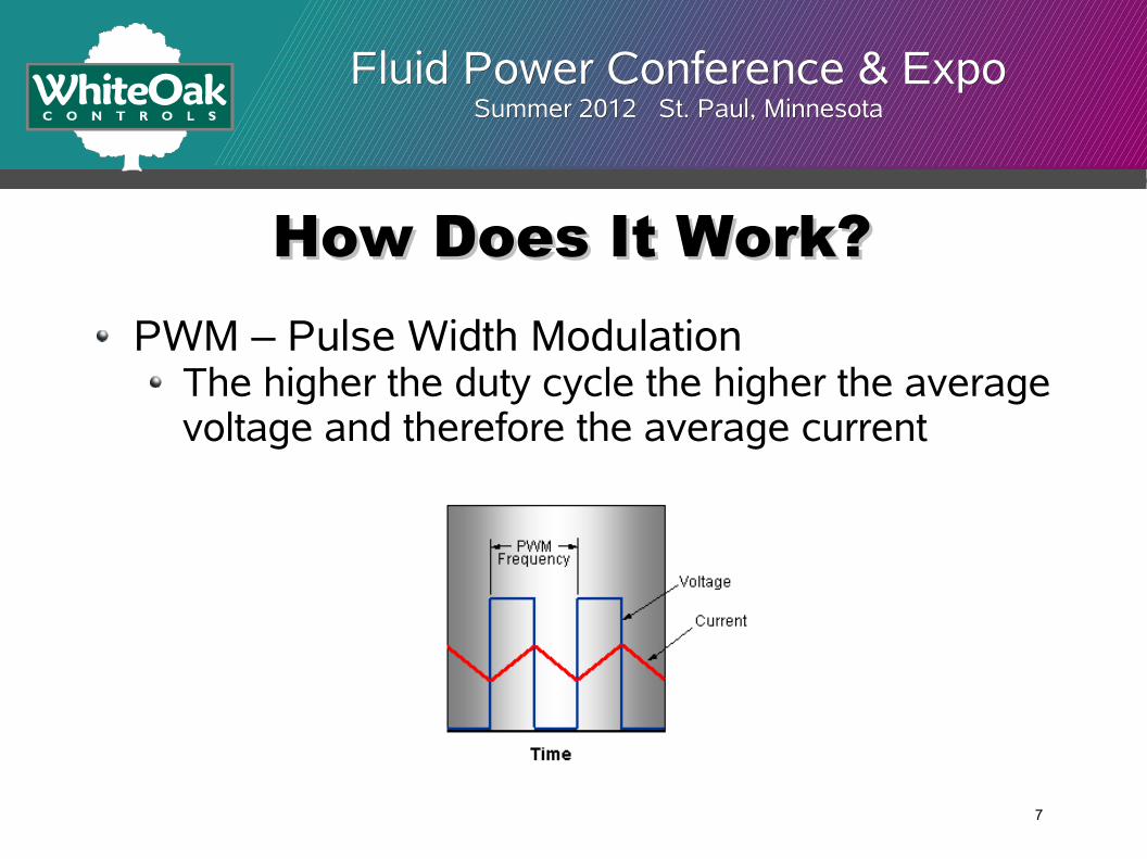
How Does It Work?How Does It Work?PWM – Pulse Width Modulation
The higher the duty cycle the higher the average voltage and therefore the average current
7
Fluid Power Conference & ExpoFluid Power Conference & ExpoSummer 2012 St. Paul, MinnesotaSummer 2012 St. Paul, Minnesota
How Does It Work?How Does It Work?Voltage control vs. current control
PWM controls the average voltage to the solenoid coilThe force developed in the solenoid is proportional to the current through the coilCurrent and voltage are related through Ohms Law by the coil resistance which changes with temperatureController must adjust PWM to maintain the desired current to the coil
8
Fluid Power Conference & ExpoFluid Power Conference & ExpoSummer 2012 St. Paul, MinnesotaSummer 2012 St. Paul, Minnesota
DitherDitherDither is a small oscillation of the output
Dither is desirable to overcome sliding friction which improves hysteresis, linearity and repeatabilityOccurs naturally as a result of PWM controlMagnitude of dither oscillation is determined by coil inductance and PWM frequencyDither frequency must be set to the optimum frequency for a given valve to be effective
9
Fluid Power Conference & ExpoFluid Power Conference & ExpoSummer 2012 St. Paul, MinnesotaSummer 2012 St. Paul, Minnesota
DitherDitherHigh and Low Frequency PWM
Low frequency PWM operates at dither frequencyHigh frequency PWM must superimpose dither
Low Frequency PWMLow Frequency PWM(80-300 Hz)(80-300 Hz)
High Frequency PWMHigh Frequency PWM(1000+ Hz)(1000+ Hz)
10
Fluid Power Conference & ExpoFluid Power Conference & ExpoSummer 2012 St. Paul, MinnesotaSummer 2012 St. Paul, Minnesota
DitherDitherDither summary
The higher the dither frequency the less effect it has on the valveToo low dither frequency will result in noticeable vibration in the systemOptimum dither frequency is the lowest frequency attainable which does not produce unwanted vibration
11
Fluid Power Conference & ExpoFluid Power Conference & ExpoSummer 2012 St. Paul, MinnesotaSummer 2012 St. Paul, Minnesota
Common ParametersCommon ParametersCommon adjustable settings include:
Dead bandGainDither frequencyMinimum and maximum inputMinimum and maximum outputRamp time
12
Fluid Power Conference & ExpoFluid Power Conference & ExpoSummer 2012 St. Paul, MinnesotaSummer 2012 St. Paul, Minnesota
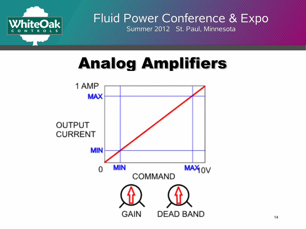
Analog AmplifiersAnalog AmplifiersTraditional settings on analog amplifiers are dead band and gainAdjusting each affects the other
13
Fluid Power Conference & ExpoFluid Power Conference & ExpoSummer 2012 St. Paul, MinnesotaSummer 2012 St. Paul, Minnesota
Analog AmplifiersAnalog Amplifiers
14
Fluid Power Conference & ExpoFluid Power Conference & ExpoSummer 2012 St. Paul, MinnesotaSummer 2012 St. Paul, Minnesota
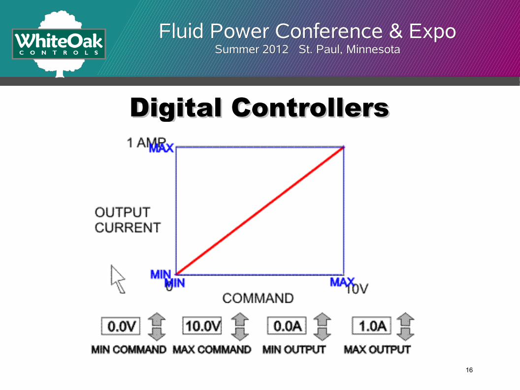
Digital ControllersDigital ControllersTypical settings for digital controllers are Minimum and Maximum Input and Output
Out (mA)
0 5 10
300
600
In Min In Max
Out Min
Out Max
Out (mA)
0 5 10
300
600
In Min In Max
Out Min
Out Max
15
Fluid Power Conference & ExpoFluid Power Conference & ExpoSummer 2012 St. Paul, MinnesotaSummer 2012 St. Paul, Minnesota
Digital ControllersDigital Controllers
16
Fluid Power Conference & ExpoFluid Power Conference & ExpoSummer 2012 St. Paul, MinnesotaSummer 2012 St. Paul, Minnesota
Common ParametersCommon ParametersOther adjustable settings:
Dither frequency is set to optimize valve performanceRamp time or rate limits how fast the valve shifts from one command level to anotherRamps may be the same for up and down or may be independent
17
Fluid Power Conference & ExpoFluid Power Conference & ExpoSummer 2012 St. Paul, MinnesotaSummer 2012 St. Paul, Minnesota
Maximum Output and Dither Frequency according to valve data sheet
18
Fluid Power Conference & ExpoFluid Power Conference & ExpoSummer 2012 St. Paul, MinnesotaSummer 2012 St. Paul, Minnesota
Typical Startup ProcedureTypical Startup Procedure1.Set Minimum Output, Maximum
Output and Dither Frequency according to valve data sheet
2.Set Minimum Input and Maximum Input according to the command signal provided. These can be preset or set interactively by applying the desired signal.
19
Fluid Power Conference & ExpoFluid Power Conference & ExpoSummer 2012 St. Paul, MinnesotaSummer 2012 St. Paul, Minnesota
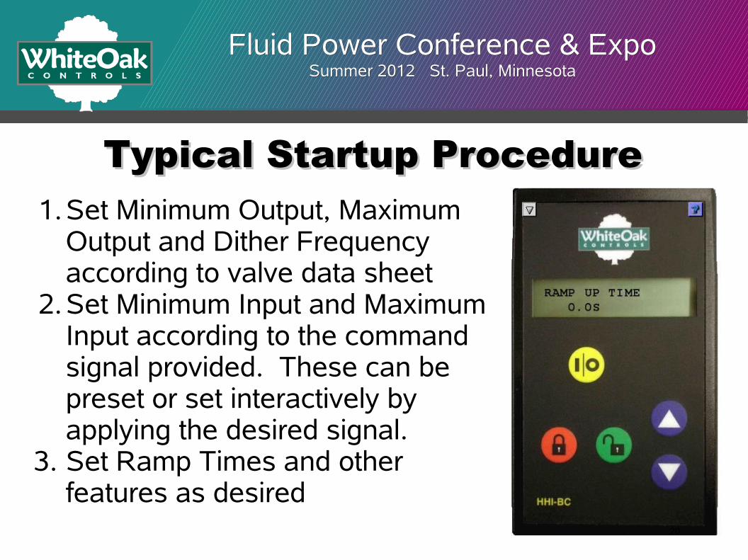
Typical Startup ProcedureTypical Startup Procedure1.Set Minimum Output, Maximum
Output and Dither Frequency according to valve data sheet
2.Set Minimum Input and Maximum Input according to the command signal provided. These can be preset or set interactively by applying the desired signal.
3. Set Ramp Times and other features as desired
20
Fluid Power Conference & ExpoFluid Power Conference & ExpoSummer 2012 St. Paul, MinnesotaSummer 2012 St. Paul, Minnesota
Typical Startup ProcedureTypical Startup Procedure1.Set Minimum Output, Maximum Output and
Dither Frequency according to valve data sheet2.Set Minimum Input and Maximum Input
according to the command signal provided. These can be preset or set interactively by applying the desired signal.
3. Set Ramp Times and other features as desired.4. Operate system through entire range to verify
desired operation5. Adjust settings as needed to limit or expand
operating envelope 21
Fluid Power Conference & ExpoFluid Power Conference & ExpoSummer 2012 St. Paul, MinnesotaSummer 2012 St. Paul, Minnesota
Other Types of ControllersOther Types of Controllers
Closed loop controllersControllers for bus systems (DeviceNet, CANopen, Profibus, etc.)Generator controllerPower saver
22
Fluid Power Conference & ExpoFluid Power Conference & ExpoSummer 2012 St. Paul, MinnesotaSummer 2012 St. Paul, Minnesota
Closed Loop ControllersClosed Loop ControllersA closed loop controller uses feedback from the process to provide more accurate controlAdded system costs include controller premium and feedback transducerPerformance improvements include linearity of less than 0.5% compared to 2-5% for open loopWith advances in electronics and sensor technology, closed loop systems are becoming an attractive option
23
Fluid Power Conference & ExpoFluid Power Conference & ExpoSummer 2012 St. Paul, MinnesotaSummer 2012 St. Paul, Minnesota
Closed Loop ControllersClosed Loop ControllersProfile settings are similar to open loop except process feedback is used in place of output current
24
Fluid Power Conference & ExpoFluid Power Conference & ExpoSummer 2012 St. Paul, MinnesotaSummer 2012 St. Paul, Minnesota
Closed Loop ControllersClosed Loop ControllersClosed loop controllers typically utilize a PID error compensation loop
P – Proportional – adds to the output an amount directly proportional to the amount of errorI – Integral – accumulates the sum of error over time and adds a portion of the sum to the outputD – Derivative – adds to the output an amount proportional to the change in error from a previous scan
25
Fluid Power Conference & ExpoFluid Power Conference & ExpoSummer 2012 St. Paul, MinnesotaSummer 2012 St. Paul, Minnesota
Closed Loop ControllersClosed Loop ControllersIn addition to the PID terms, time factors also affect the loop performance
Loop closure time – the faster the loop closure, the more responsive the systemIntegration time – the integral time is often a separate parameter to fine tune the integral portion of the equation
26
Fluid Power Conference & ExpoFluid Power Conference & ExpoSummer 2012 St. Paul, MinnesotaSummer 2012 St. Paul, Minnesota
Addressable Bus SystemsAddressable Bus SystemsController is designed to receive commands from bus system such as DeviceNet, CanOpen, or ProfibusSimplifies wiring by requiring only 2 power wires and 2 bus wires from device to deviceCan provide diagnostic information to the controlling system
27
Fluid Power Conference & ExpoFluid Power Conference & ExpoSummer 2012 St. Paul, MinnesotaSummer 2012 St. Paul, Minnesota
Generator ControllerGenerator ControllerClosed loop proportional valve controller for driving a generatorMonitors AC line to maintain proper frequency with changes in loadExample of a general purpose controller modified to fill a specific need
28
Fluid Power Conference & ExpoFluid Power Conference & ExpoSummer 2012 St. Paul, MinnesotaSummer 2012 St. Paul, Minnesota
Power SaverPower SaverPower saver or coil saver initially applies full power to the coil and then reduces power to a lower holding levelUsed to reduce power consumption in switching valvesReduces heat buildup to prolong coil lifeCan be used in some cases to operate coils at voltages other than design voltage, such as driving a 12 volt coil in a 24 volt system
29
Fluid Power Conference & ExpoFluid Power Conference & ExpoSummer 2012 St. Paul, MinnesotaSummer 2012 St. Paul, Minnesota
SummarySummaryNearly all types of proportional valve controllers utilize the same underlying PWM technologyTerms and settings are similar among products from different manufacturersDigital controllers offer more functionality and tend to be easier to setupAdvances in technology are enabling more performance at a lower costThere are specialized controllers available that can be adapted to a multitude of uses