26


Presents
Introduction to
Compressors
Revision 1
Web Site: www.idc-online.com
E-mail: [email protected]

Copyright
All rights to this publication, associated software and workshop are reserved.
No part of this publication or associated software may be copied, reproduced,
transmitted or stored in any form or by any means (including electronic,
mechanical, photocopying, recording or otherwise) without prior written
permission of IDC Technologies.
Disclaimer
Whilst all reasonable care has been taken to ensure that the descriptions,
opinions, programs, listings, software and diagrams are accurate and workable,
IDC Technologies do not accept any legal responsibility or liability to any
person, organization or other entity for any direct loss, consequential loss or
damage, however caused, that may be suffered as a result of the use of this
publication or the associated workshop and software.
In case of any uncertainty, we recommend that you contact IDC Technologies
for clarification or assistance.
Trademarks
All terms noted in this publication that are believed to be registered
trademarks or trademarks are listed below:
IBM, XT and AT are registered trademarks of International Business
Machines Corporation. Microsoft, MS-DOS and Windows are registered
trademarks of Microsoft Corporation.
Acknowledgements
IDC Technologies expresses its sincere thanks to all those engineers and
technicians on our training workshops who freely made available their
expertise in preparing this manual.
Who is IDC Technologies?
IDC Technologies is a specialist in the field of industrial communications,
telecommunications, automation and control and has been providing high
quality training for more than six years on an international basis from
offices around the world.
IDC consists of an enthusiastic team of professional engineers and support
staff who are committed to providing the highest quality in their consulting
and training services. The Benefits to you of Technical Training Today
The technological world today presents tremendous challenges to engineers,
scientists and technicians in keeping up to date and taking advantage of the
latest developments in the key technology areas.
The immediate benefits of attending IDC workshops are:
Gain practical hands-on experience
Enhance your expertise and credibility
Save $$$s for your company
Obtain state of the art knowledge for your company
Learn new approaches to troubleshooting
Improve your future career prospects
The IDC Approach to Training
All workshops have been carefully structured to ensure that attendees gain
maximum benefits. A combination of carefully designed training software,
hardware and well written documentation, together with multimedia
techniques ensure that the workshops are presented in an interesting,
stimulating and logical fashion.
IDC has structured a number of workshops to cover the major areas of
technology. These courses are presented by instructors who are experts in
their fields, and have been attended by thousands of engineers, technicians
and scientists world-wide (over 11,000 in the past two years), who have
given excellent reviews. The IDC team of professional engineers is
constantly reviewing the courses and talking to industry leaders in these
fields, thus keeping the workshops topical and up to date.
Technical Training Workshops
IDC is continually developing high quality state of the art workshops aimed
at assisting engineers, technicians and scientists. Current workshops
include:
Instrumentation & Control
Practical Automation and Process Control using PLC’s
Practical Data Acquisition using Personal Computers and Standalone
Systems
Practical On-line Analytical Instrumentation for Engineers and
Technicians
Practical Flow Measurement for Engineers and Technicians
Practical Intrinsic Safety for Engineers and Technicians
Practical Safety Instrumentation and Shut-down Systems for Industry
Practical Process Control for Engineers and Technicians
Practical Programming for Industrial Control – using (IEC 1131-3;OPC)
Practical SCADA Systems for Industry
Practical Boiler Control and Instrumentation for Engineers and
Technicians
Practical Process Instrumentation for Engineers and Technicians
Practical Motion Control for Engineers and Technicians
Practical Communications, SCADA & PLC’s for Managers
Communications
Practical Data Communications for Engineers and Technicians
Practical Essentials of SNMP Network Management
Practical Field Bus and Device Networks for Engineers and Technicians
Practical Industrial Communication Protocols
Practical Fibre Optics for Engineers and Technicians
Practical Industrial Networking for Engineers and Technicians
Practical TCP/IP & Ethernet Networking for Industry
Practical Telecommunications for Engineers and Technicians
Practical Radio & Telemetry Systems for Industry
Practical Local Area Networks for Engineers and Technicians
Practical Mobile Radio Systems for Industry
Electrical
Practical Power Systems Protection for Engineers and Technicians
Practical High Voltage Safety Operating Procedures for Engineers &
Technicians
Practical Solutions to Power Quality Problems for Engineers and
Technicians
Practical Communications and Automation for Electrical Networks
Practical Power Distribution
Practical Variable Speed Drives for Instrumentation and Control Systems
Project & Financial Management
Practical Project Management for Engineers and Technicians
Practical Financial Management and Project Investment Analysis
How to Manage Consultants
Mechanical Engineering
Practical Boiler Plant Operation and Management for Engineers and
Technicians
Practical Centrifugal Pumps – Efficient use for Safety & Reliability
Electronics
Practical Digital Signal Processing Systems for Engineers and Technicians
Practical Industrial Electronics Workshop
Practical Image Processing and Applications
Practical EMC and EMI Control for Engineers and Technicians
Information Technology
Personal Computer & Network Security (Protect from Hackers, Crackers
& Viruses)
Practical Guide to MCSE Certification
Practical Application Development for Web Based SCADA
Comprehensive Training Materials
Workshop Documentation
All IDC workshops are fully documented with complete reference materials
including comprehensive manuals and practical reference guides.
Software
Relevant software is supplied with most workshops. The software consists
of demonstration programs which illustrate the basic theory as well as the
more difficult concepts of the workshop.
Hands-On Approach to Training
The IDC engineers have developed the workshops based on the practical
consulting expertise that has been built up over the years in various
specialist areas. The objective of training today is to gain knowledge and
experience in the latest developments in technology through cost effective
methods. The investment in training made by companies and individuals is
growing each year as the need to keep topical and up to date in the industry
in which they are operating is recognized. As a result, the IDC instructors
place particular emphasis on the practical hands-on aspect of the workshops
presented.
On-Site Workshops
In addition to the quality of workshops which IDC presents on a world-wide
basis, all IDC courses are also available for on-site (in-house) presentation
at our client’s premises. On-site training is a cost effective method of
training for companies with many delegates to train in a particular area.
Organizations can save valuable training $$$’s by holding courses on-site,
where costs are significantly less. Other benefits are IDC’s ability to focus
on particular systems and equipment so that attendees obtain only the
greatest benefits from the training.
All on-site workshops are tailored to meet with clients training requirements
and courses can be presented at beginners, intermediate or advanced levels
based on the knowledge and experience of delegates in attendance. Specific
areas of interest to the client can also be covered in more detail. Our
external workshops are planned well in advance and you should contact us
as early as possible if you require on-site/customized training. While we
will always endeavor to meet your timetable preferences, two to three
month’s notice is preferable in order to successfully fulfil your
requirements. Please don’t hesitate to contact us if you would like to discuss
your training needs.
Customized Training
In addition to standard on-site training, IDC specializes in customized
courses to meet client training specifications. IDC has the necessary
engineering and training expertise and resources to work closely with clients
in preparing and presenting specialized courses.
These courses may comprise a combination of all IDC courses along with
additional topics and subjects that are required. The benefits to companies
in using training are reflected in the increased efficiency of their operations
and equipment.
Training Contracts
IDC also specializes in establishing training contracts with companies who
require ongoing training for their employees. These contracts can be
established over a given period of time and special fees are negotiated with
clients based on their requirements. Where possible, IDC will also adapt
courses to satisfy your training budget.
References from various international companies to whom IDC is contracted
to provide on-going technical training are available on request.
Some of the thousands of Companies worldwide that have
supported and benefited from IDC workshops are:
Alcoa, Allen-Bradley, Altona Petrochemical, Aluminum Company of
America, AMC Mineral Sands, Amgen, Arco Oil and Gas, Argyle Diamond
Mine, Associated Pulp and Paper Mill, Bailey Controls, Bechtel,
BHP Engineering, Caltex Refining, Canon, Chevron, Coca-Cola,
Colgate-Palmolive, Conoco Inc, Dow Chemical, ESKOM, Exxon,
Ford, Gillette Company, Honda, Honeywell, Kodak, Lever Brothers,
McDonnell Douglas, Mobil, Modicon, Monsanto, Motorola, Nabisco,
NASA, National Instruments, National Semi-Conductor, Omron Electric,
Pacific Power, Pirelli Cables, Proctor and Gamble, Robert Bosch Corp,
Siemens, Smith Kline Beecham, Square D, Texaco, Varian,
Warner Lambert, Woodside Offshore Petroleum, Zener Electric
Table of Contents
1.0 Introduction to Compressors 1
1.1 What is a Compressor? ……………………………………………………. 3
1.1.1 Positive Displacement Compressors ………………………………. 3
1.1.2 Reciprocating compressors………………………………………… 4
1.1.3 Screw compressors………………………………………………….5
1.1.4 Vane compressors…………………………………………………...6
1.1.5 Lobe compressors………………………………………………….. 7
1.1.6 Liquid ring/piston compressors……………………………………..8
1.1.7 Diaphragm compressors…………………………………………….9
1.1.8 Dynamic compressors……………………………………………… 9
1.2 Compressor definitions…………………………………………………….. 10
1.2.1 Gauge pressure……………………………………………………... 10
1.2.2 Absolute pressure…………………………………………………... 10
1.2.3 Absolute temperature………………………………………………..11
1.2.4 Pressure ratio………………………………………………………..11
1.2.5 Capacity……………………………………………………………..11
1.2.6 Stages………………………………………………………………..12
1.2.7 Basic criteria for compressor selection……………………………...12


01 Introduction to Compressors

Practical Pumps and Compressors
2
Compressors
3
1.0 Compressors
1.1 What is a compressor?
In our bouquet of childhood memories, there lies one of using the bicycle pump
for the first time. Few can forget the trickling sweat and satisfactory feel of the
hard bicycle tyre. For many, that was probably the first experience of operating a
compressor.
From inflating footballs to spray painting, from vacuum cleaners to refrigerators,
from ventilators to air conditioners, from the dentist’s whining drill to the
deafening pneumatic hammers on construction sites, there are few aspects in our
present day life that remain untouched by the need of air or some gas at higher
pressures.
These and countless more requirements have evolved and sustained the demand
for machines that capture a volume of gas and raises its pressure. These machines
are called fans, blowers or compressors.
Compressors transfer energy to a gaseous fluid for raising the pressure of a gas. It
can also be regarded as an engine driving a gas from one part of the process to
another.
Pressure is often expressed in the units of kg/cm2 or psi (pounds per square inch).
Fans, blowers or compressors are distinguished by their ability to raise the
pressure of the gas they handle.
If suction of the atmospheric air (0 kg/cm2-g) is considered, devices that can
develop pressure to 0.1 kg/cm2-g are called fans. Blowers are stronger and can
build a pressure to 0.9 kg/cm2-g. Pressurizing devices above this range are called
compressors.
There are basically two types of compressors:
Positive displacement compressors
Dynamic compressors
1.1.1 Positive displacement compressors
The old bicycle pump (a misnomer) remains the most well known positive
displacement compressor. It comprises of a piston that moves to and fro in a metal
cylinder. As the piston is pulled up, it sucks in a certain volume of air. During the
“push” or the downward stroke of the piston, the air trapped between the moving
piston and the cylinder is compressed into a smaller volume. This compression
causes an increase in pressure. At the instant when the air pressure inside the
cylinder exceeds that in the cycle tyre, air is forced into the tyre tube.
Positive displacement compressors entrap a volume of gas in a confined space.
The volume of this space is reduced, leading to a reduction in the volume of the
gas. This raises the pressure of the gas. After the pressure of the gas has been
raised, it is pushed out of the confined space.
Positive displacement compressors for a given speed are typically constant flow,
variable pressure ratio (ratio of the discharge pressure to the suction pressure)
machines. The volume of gas compressed is directly proportional to the speed of
Practical Pumps and Compressors
4
the compressor. The above can be understood using the example of the bicycle
pump. It is easy to imagine that the volume of air being delivered during every
stroke of the pump would remain the same as long as the travel of the piston or
the stroke remained the same. If the number of strokes per minute increased, the
total volume of delivered air would also increase proportionately.
In the initial stages, when the tyre is flat, the pressure inside the tyre is less. The
pump builds lesser pressure to push the air inside. However, as the tyre becomes
filled, the discharge pressure of the pump rises to match the tyre pressure. We
observe that this device can vary its discharge pressure to match the system
requirement. Hence, these are variable pressure ratio machines.
Such compressors normally handle smaller volumes of gas. The various types of
positive displacement compressors are:
1.1.2 Reciprocating compressors
In reciprocating compressors, successive volumes of gas are confined within a
closed space and elevated to a higher pressure by forcing the mass of gas into a
smaller volume.
It usually comprises of a circular piston, which traverses back and forth along a
linear path inside a cylinder. It has valves on the suction and discharge ends. With
every suction stroke of the piston, the gas is taken into the cylinder. In the forward
stroke, the gas is trapped as both the suction and discharge valves are closed.
Midway during the forward stroke, when the gas pressure inside the cylinder
becomes higher than the system into which it has to deliver, the discharge valve
opens. Subsequently, the compressed gas is pushed into the system at its pressure.
The reciprocating mechanism is hundreds of years old, but the modern design of
the reciprocating compressor is believed to have been derived from the steam
engine.
This slider-crank mechanism adopted in the above machines comprises of a
rotating crankshaft. This rotary motion is converted to a linear motion of the
piston by a connecting rod. This rod has an oscillatory motion. In a steam engine,
the steam pushes the piston and a rotary motion is derived from the crankshaft,
whereas, in a compressor, the rotary motion of the crankshaft is used to
reciprocate the piston to entrap and compress the gas.
Therefore, although they may have similar mechanisms, thermodynamically, they
are opposite in nature. One has the gas doing the work and in the other, work is
done on the gas. One is a prime mover and the other is a driven machine.
Thomas Newcomen designed a reciprocating steam engine in the eighteenth
century that used a true piston and piston rod assembly. James Watt built a piston
using brass rings in the late 1700s. He patented his single-acting steam engine in
1769 and patented his double-acting steam engine in 1782.
The invention of the reciprocating compressor is vague. Many countries had been
using steam engines and the technology produced reciprocating compressors.
Compressors
5
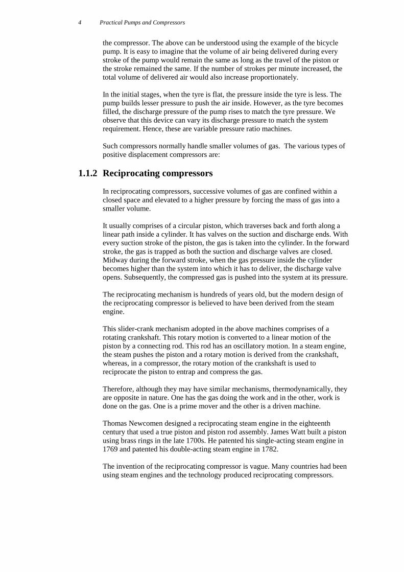
1.1.3 Screw compressors
Screw compressors belong to the family of positive displacement compressors. In
fact, they are often termed rotary piston compressors.
A screw compressor comprises of two intermeshing lobes: one male and the other
female. Each one has a helical form. A volume space is formed by the helical
profiles of the two lobes and the casing. The gas from the inlet is trapped within
this space. As the lobes rotate, this volume that entraps the gas reduces and moves
in a forward direction. This reduction in volume compresses the gas and transfers
it from the inlet or the suction to the discharge vessel.
A Screw Compressor
Heinrich Krigar in Germany first patented the principle of the screw compressor
in 1878. He modified and improved his designs, and lodged a second patent a few
months later in the same year.
He lived in Hannover. The illustrations of his compressor clearly show a two-
lobe rotor assembly, with each rotor having similar profiles. In fact, the rotor
configuration resembles the lobe design initially exhibited in Europe in 1867, with
the exception that the rotors in the Krigar screw compressor twisted through an
angle of 180° along their length of the lobe.
It was not possible to develop the idea any further at that time due to the lack of
manufacturing technology. Almost 50 years later, Ljungstroms Angturbin AB, a
Swedish steam turbine manufacturer, appointed a new Chief Engineer, named Alf
Lysholm.
He played a pivotal role in the development of the modern screw compressor. At
that time, Lysholm was interested in developing a lightweight compressor for gas
and steam turbine applications. By this time, the original patent rights had
expired.
Lysholm developed the profile of the screw compressor, and tested various
configurations and rotor lobe combinations. He not only designed the rotor
configurations, but also evolved a methodology to machine them accurately. He
eventually had it patented. This patent in 1935 probably signalled the arrival of
the modern screw compressor.
The company Ljungstroms Angturbin AB later changed its name to Svenska
Rotor Maskiner AB in 1951. This company is well known throughout the world
as SRM.
Several other compressor manufacturers have since invested in their own R&D
programs to produce new ‘in-house’ profiles, all based on an initial concept which
Practical Pumps and Compressors
6
is now over 120 years old.
Screw compressor design involves rotating components that do not have any
physical contact. This greatly enhances their availability when compared to the
reciprocating compressors. The gas flow does not have pressure pulses and
usually, the capacity is higher than the reciprocating machines.
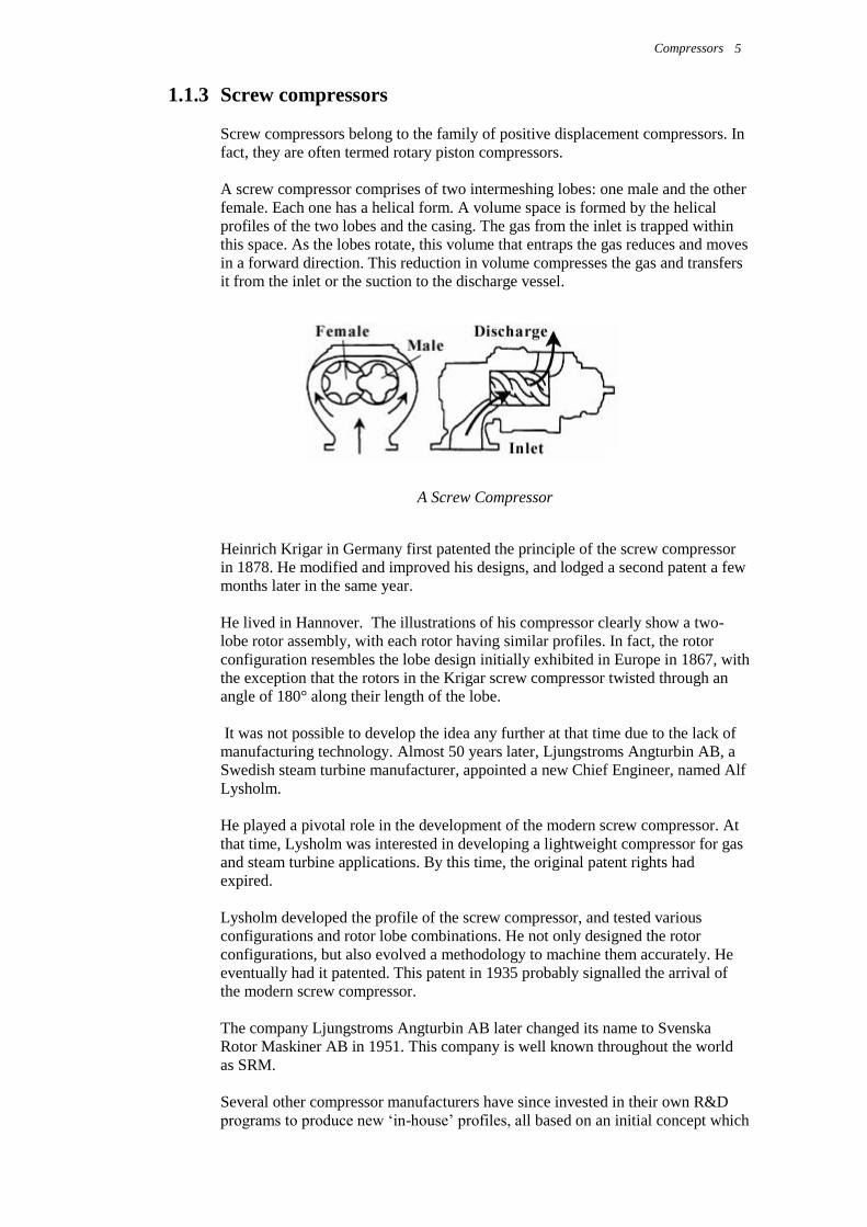
1.1.4 Vane compressors
These are rotary positive displacement machines in which axial vanes slide
rapidly in rotor eccentrically mounted in a cylindrical casing.
A Vane Compressor
The vanes are thrown outward by centrifugal force when the compressor is
running. The vanes move in and out of the slot as the rotor is eccentric to the
casing. The vanes sweep the cylinder. Gas trapped between consecutive vanes is
compressed and displaced.
Rotary vane compressors use either carbon vanes for low-pressure, oil-free duties,
or asbestos/steel vanes for lubricated duties. The present day vanes are made of
advanced thermoplastics called polyamide imides. Various asbestos (and similar
performance asbestos free) compounds are also widely used for low-pressure
applications. Over and above the pressure of 3 bar-g, the vanes are steel or cast
iron, due to excessive bending forces that act on the vanes when the machine is
running.
The Lemielle exhauster was one of the first vane type machines invented in
France during the early 1800s, and widely used in Belgium to provide ventilation
for collieries.
In this large machine, hinged vanes were mounted on the surface of a rotating
drum. This drum was mounted eccentrically within a casing. The vane travel was
limited to ensure a semi-contact with the outer casing. It did not take long to
graduate to the present design of sliding vanes.
The principle of the modern sliding vane compressor dates back to the early
1900s when Robert Blackmer, an American, invented the first rotary vane pump.
Pneumofore SPA, an Italian manufacturer first produced the oil-injected sliding
vane compressor in the late 1920s. Toward the end of the 1940s, Major P.C. Bird
patented a new type of lubricated vane compressor in the UK under the trade
name ‘Oilvane’. Alfred Bullows acquired an exclusive license from Major Bird,
and after a period of development, the first Hydrovane compressors followed.
Compressors
7
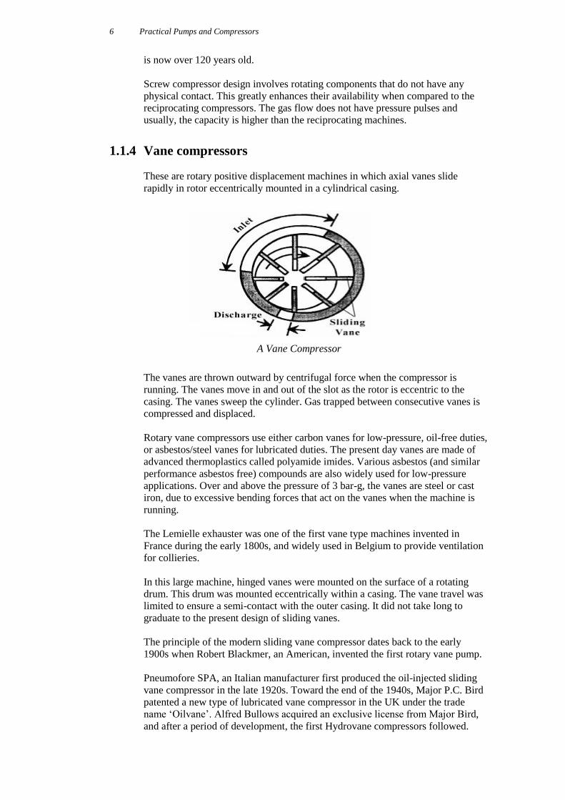
1.1.5 Lobe compressors
Lobe compressors are of a rotary type also. Two straight mating lobes trap the gas
between the lobe profile and the casing. Their rotation displaces the gas from the
suction to discharge with no internal compression.
A Lobe Compressor
Compression is caused as the induced gas is forced into a closed conduit, thereby
causing the gas to become pressurized after it has left the lobe compressor.
Philander and Francis, the Roots brothers, discovered the principle of the lobes
blower in the mid 1800s. They were joint owners of a woolen mill in
Connersville, Indiana. This positive displacement blower was named after them
and the original Roots Blower Company was formed. The name Roots blower has
almost become synonymous to this generic type of compressor/blower.
The Roots blower was exhibited in Paris during 1867 and was seen as a possible
answer to the then difficult problems of deep mine ventilation.
About 40 years later, a rival blower manufacturer was formed in the same city,
called Connersville Blowers. The companies competed with each other until
1931, when they were both bought out by a third party and merged.
Lobe compressors are typically used to produce low-pressure compressed air.
They have many applications and one of the main uses is in pneumatic conveying
of powders. In this application, the powder flows in the same way as a liquid.
Pneumatic conveying is usually carried out at fairly low pressures, between 5 psig
and 15 psig depending on the nature of the material being conveyed.
Practical Pumps and Compressors
8
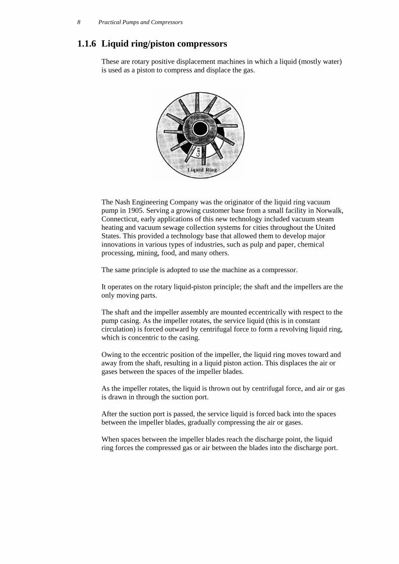
1.1.6 Liquid ring/piston compressors
These are rotary positive displacement machines in which a liquid (mostly water)
is used as a piston to compress and displace the gas.
The Nash Engineering Company was the originator of the liquid ring vacuum
pump in 1905. Serving a growing customer base from a small facility in Norwalk,
Connecticut, early applications of this new technology included vacuum steam
heating and vacuum sewage collection systems for cities throughout the United
States. This provided a technology base that allowed them to develop major
innovations in various types of industries, such as pulp and paper, chemical
processing, mining, food, and many others.
The same principle is adopted to use the machine as a compressor.
It operates on the rotary liquid-piston principle; the shaft and the impellers are the
only moving parts.
The shaft and the impeller assembly are mounted eccentrically with respect to the
pump casing. As the impeller rotates, the service liquid (this is in constant
circulation) is forced outward by centrifugal force to form a revolving liquid ring,
which is concentric to the casing.
Owing to the eccentric position of the impeller, the liquid ring moves toward and
away from the shaft, resulting in a liquid piston action. This displaces the air or
gases between the spaces of the impeller blades.
As the impeller rotates, the liquid is thrown out by centrifugal force, and air or gas
is drawn in through the suction port.
After the suction port is passed, the service liquid is forced back into the spaces
between the impeller blades, gradually compressing the air or gases.
When spaces between the impeller blades reach the discharge point, the liquid
ring forces the compressed gas or air between the blades into the discharge port.
Compressors
9
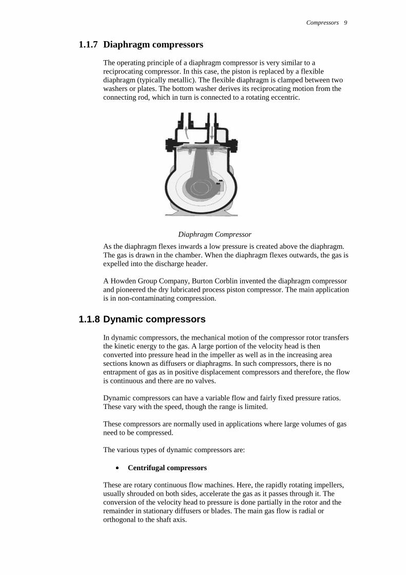
1.1.7 Diaphragm compressors
The operating principle of a diaphragm compressor is very similar to a
reciprocating compressor. In this case, the piston is replaced by a flexible
diaphragm (typically metallic). The flexible diaphragm is clamped between two
washers or plates. The bottom washer derives its reciprocating motion from the
connecting rod, which in turn is connected to a rotating eccentric.
Diaphragm Compressor
As the diaphragm flexes inwards a low pressure is created above the diaphragm.
The gas is drawn in the chamber. When the diaphragm flexes outwards, the gas is
expelled into the discharge header.
A Howden Group Company, Burton Corblin invented the diaphragm compressor
and pioneered the dry lubricated process piston compressor. The main application
is in non-contaminating compression.
1.1.8 Dynamic compressors
In dynamic compressors, the mechanical motion of the compressor rotor transfers
the kinetic energy to the gas. A large portion of the velocity head is then
converted into pressure head in the impeller as well as in the increasing area
sections known as diffusers or diaphragms. In such compressors, there is no
entrapment of gas as in positive displacement compressors and therefore, the flow
is continuous and there are no valves.
Dynamic compressors can have a variable flow and fairly fixed pressure ratios.
These vary with the speed, though the range is limited.
These compressors are normally used in applications where large volumes of gas
need to be compressed.
The various types of dynamic compressors are:
Centrifugal compressors
These are rotary continuous flow machines. Here, the rapidly rotating impellers,
usually shrouded on both sides, accelerate the gas as it passes through it. The
conversion of the velocity head to pressure is done partially in the rotor and the
remainder in stationary diffusers or blades. The main gas flow is radial or
orthogonal to the shaft axis.
Practical Pumps and Compressors
10
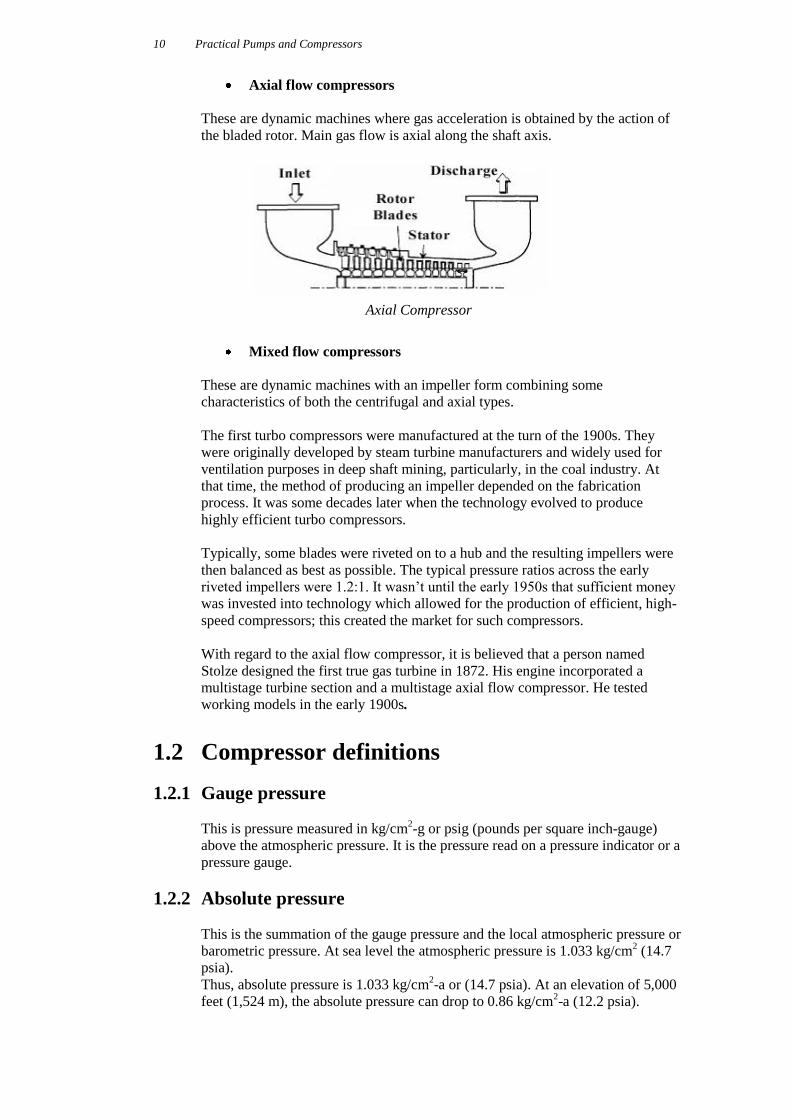
Axial flow compressors
These are dynamic machines where gas acceleration is obtained by the action of
the bladed rotor. Main gas flow is axial along the shaft axis.
Axial Compressor
Mixed flow compressors
These are dynamic machines with an impeller form combining some
characteristics of both the centrifugal and axial types.
The first turbo compressors were manufactured at the turn of the 1900s. They
were originally developed by steam turbine manufacturers and widely used for
ventilation purposes in deep shaft mining, particularly, in the coal industry. At
that time, the method of producing an impeller depended on the fabrication
process. It was some decades later when the technology evolved to produce
highly efficient turbo compressors.
Typically, some blades were riveted on to a hub and the resulting impellers were
then balanced as best as possible. The typical pressure ratios across the early
riveted impellers were 1.2:1. It wasn’t until the early 1950s that sufficient money
was invested into technology which allowed for the production of efficient, high-
speed compressors; this created the market for such compressors.
With regard to the axial flow compressor, it is believed that a person named
Stolze designed the first true gas turbine in 1872. His engine incorporated a
multistage turbine section and a multistage axial flow compressor. He tested
working models in the early 1900s.
1.2 Compressor definitions
1.2.1 Gauge pressure
This is pressure measured in kg/cm2-g or psig (pounds per square inch-gauge)
above the atmospheric pressure. It is the pressure read on a pressure indicator or a
pressure gauge.
1.2.2 Absolute pressure
This is the summation of the gauge pressure and the local atmospheric pressure or
barometric pressure. At sea level the atmospheric pressure is 1.033 kg/cm2 (14.7
psia).
Thus, absolute pressure is 1.033 kg/cm2-a or (14.7 psia). At an elevation of 5,000
feet (1,524 m), the absolute pressure can drop to 0.86 kg/cm2-a (12.2 psia).
Compressors
11
1.2.3 Absolute temperature
This is obtained by adding the actual measured temperature in °C + 273.16. The
units for this temperature value are in °K (Kelvin).
°K = °C + 273.16
When the measured temperature is in °F, the absolute temperature is obtained by
adding 460 to the measured reading. The units for the absolute temperature in this
case are °R (Rankine).
°R = °F + 460
1.2.4 Pressure ratio
Pressure ratio is the ratio of the discharge pressure to the suction pressure
considered in absolute values.
If the suction and discharge pressure gauges indicate 1.6 kg/cm2 and 6.5 kg/cm
2,
then the pressure ratio is:
PR = (6.5 + 1.033) / (1.6 + 1.033) = 2.861
1.2.5 Capacity
Compressors are volumetric machines. This implies that for any gas handled, the
volume of gas derived is the same. The volume of gas handled by the compressor
is known as the capacity of the compressor.
However, the problem is that volume at different inlet conditions can be different;
therefore, there is a need to specify the inlet conditions when the capacity of a
compressor is referred.
There are three conditions at which compressor capacity can be stated:
Normal (sea level, 0°C)
Standard
o [Compressed Air Institute – 1.033 kg/cm2-a (14.7 psia), 15.5ºC,
(60ºF)]
o [ASME - 1.033 kg/cm2-a (14.7 psia), 20ºC (68ºF), RH – 36%]
o [Natural Gas Pipeline Industry – 1.012 kg/cm2-a (14.2 psia),
Suction temperature]
Inlet (compressor suction conditions)
The Inlet condition is mostly specified and it is common to come across ICFM
(inlet cubic feet per minute) or ACFM (actual cubic feet per minute). CFM in
metric units is meter cube per hour (m3/hr). Also, when no conditions are
specified, it can be assumed that inlet conditions are being considered.
Practical Pumps and Compressors
12
1.2.6 Stages
In many cases an application may require gas to be raised to a high-pressure ratio.
This may be beyond the design capability of the compressor to accomplish with
one step. As a result, compression is split into two or more steps, known as stages.
As the gas is compressed, its temperature rises. Therefore, in a multistage
compressor, gas is cooled in a heat exchanger after every stage and then led to the
inlet of the next stage. This method of inter-cooling the gas reduces the energy
required to compress it.
1.2.7 Basic criteria for compressor selection
Prior to selecting the type of compressor, various factors need to be taken into
consideration. Some of these include:
Capacity
Pressure ratio
Power supply characteristics
Size and weight of compressor
Type of foundation required
Type of controls
Maintenance costs
Availability and cost of cooling water
The prime factors of capacity and pressure ratio are the first to be used to choose
between positive displacement and dynamic compressors. A further selection
between the two broad types is an engineering decision based on many additional
factors such as lifecycle, cost and the process involved.
Compressors
13
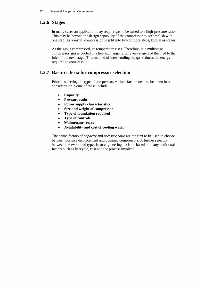
The above is an approximate application range for the different types of
compressors.
Here, the numbers on the X-Y axes are powers of 10 for actual cubic feet per
minute (ACFM) and discharge pressure in pounds per square inch (psi).
1 CFM = 1.7 m3/hr, and
1 psi = 0.07 kg/cm2.
Practical Pumps and Compressors
14
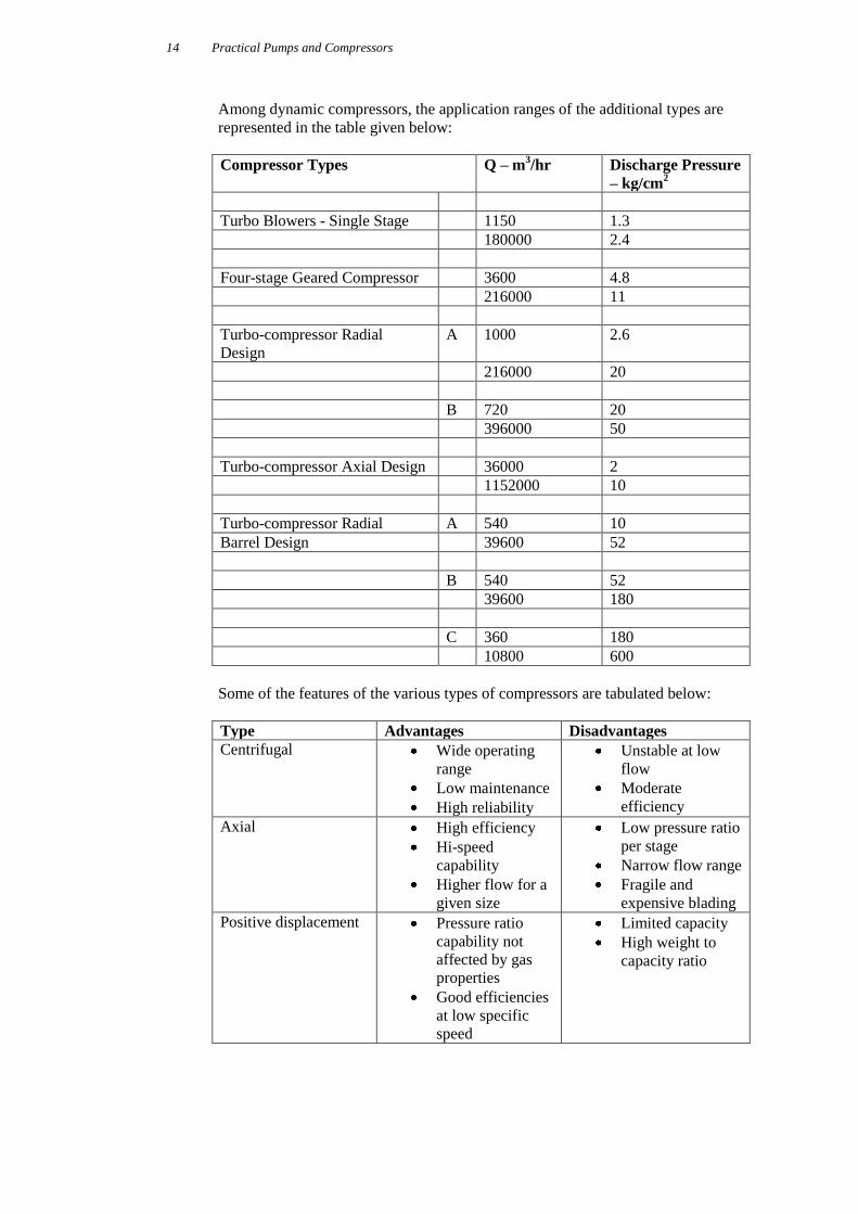
Among dynamic compressors, the application ranges of the additional types are
represented in the table given below:
Compressor Types Q – m3/hr Discharge Pressure
– kg/cm2
Turbo Blowers - Single Stage 1150 1.3
180000 2.4
Four-stage Geared Compressor 3600 4.8
216000 11
Turbo-compressor Radial
Design
A 1000 2.6
216000 20
B 720 20
396000 50
Turbo-compressor Axial Design 36000 2
1152000 10
Turbo-compressor Radial A 540 10
Barrel Design 39600 52
B 540 52
39600 180
C 360 180
10800 600
Some of the features of the various types of compressors are tabulated below:
Type Advantages Disadvantages
Centrifugal Wide operating
range
Low maintenance
High reliability
Unstable at low
flow
Moderate
efficiency
Axial High efficiency
Hi-speed
capability
Higher flow for a
given size
Low pressure ratio
per stage
Narrow flow range
Fragile and
expensive blading
Positive displacement Pressure ratio
capability not
affected by gas
properties
Good efficiencies
at low specific
speed
Limited capacity
High weight to
capacity ratio
Practical Pumps and Compressors Control, Operation, Maintenance and Troubleshooting
YOU MAY ALSO BE INTERESTED IN THE FOLLOWING TITLE:
This book is available for purchase in
printed form or as an ebook
For more details about this title
please visit the link below:
http://idc-online.com/books/mechanical_engineering/category=mechanical&booked=63
If you would like a quote or any further information please do not hesitate to contact us:


