NIBCO INC. WORLD HEADQUARTERS • 1516 MIDDLEBURY ST. • ELKHART, IN 46516-4740 • USA • PH: 1.800.234.0227 TECH SERVICES PH: 1.888.446.4226 • FAX: 1.888.234.0557 • INTERNATIONAL OFFICE PH: +1.574.295.3327 • FAX: +1.574.295.3455 www.nibco.com 13 AHEAD OF THE FLOW ® www.nibco.com Dezincification Resistant NIBCO ® Press System ® Bronze Ball Valves Two-Piece Body • Full Port • Bronze Trim • Blowout-Proof Stem 250 PSI/17.2 Bar Non-Shock Cold Working Pressure 250°F Maximum Operating Temperature CONFORMS TO MSS SP-110 MATERIAL LIST PART SPECIFICATION 1. Body Bronze ASTM B584 Alloy C84400 2. Body End Bronze ASTM B584 Alloy C84400 3. Press End Adapter (2) Wrot Copper ASTM B75 Alloy C12200 4. Ball Brass ASTM B16 Alloy C36000 or ASTM B283 Alloy C37700 (Chrome/Nickel Plated) 5. Seat Ring (2) Reinforced PTFE 6. Boss seal o-ring (2) EPDM 7. O-Ring (2) EPDM 8. Packing PTFE 9. Pack Gland Brass ASTM B16 Alloy C36000 10. Stem Silicon Bronze ASTM B371 Alloy C69430 or ASTM B371 Alloy C69430 11. Handle Nut Zinc Plated Steel 12. Thrust Washer Reinforced PTFE 13. Handle Assembly Zinc Plated Steel with Plastisol Coating PC585-70 P x P NIBCO ® Press System ® ball valves are designed to meet MSS SP-110 with the exception of the end connection. Ball valves are down-rated from 600 PSI CWP to 250 PSI CWP to match the Press System ® . Male and female press-to-connect ends are new technology not yet covered in the current edition of this specification. PC585-70 Press x Press Female End Dimensions SIZE A B C D E Weight In. mm. In. mm. In. mm. In. mm. In. mm. In. mm. Lbs. Kg. 1/2” 13 2.76 70 1.90 48 6.00 152 .50 13 4.15 105 .80 .36 3/4” 19 3.28 83 2.28 58 7.29 185 .75 19 5.05 128 1.56 .71 1” 25 3.59 91 2.41 61 7.34 186 1.00 25 5.36 136 2.13 1.00 1” 32 4.62 117 3.05 77 10.04 255 1.25 32 6.64 169 3.73 1.69 1” 38 5.23 133 3.30 84 10.72 272 1.50 38 8.00 203 5.53 2.51 2” 50 5.63 143 3.51 89 11.05 281 2.00 50 8.65 220 7.95 3.61 DIMENSIONS—WEIGHTS Revised 1/6/2014 Handle Options: • Stainless Steel Lever • NIB-Seal ® • Locking lever • Stainless Steel Locking Lever • Memory stop • Extended lever w/ memory stop • Round • Wing • Horizontal and vertical chain
Transcript
NIBCO INC. WORLD HEADQUARTERS • 1516 MIDDLEBURY ST. • ELKHART, IN 46516-4740 • USA • PH: 1.800.234.0227 TECH SERVICES PH: 1.888.446.4226 • FAX: 1.888.234.0557 • INTERNATIONAL OFFICE PH: +1.574.295.3327 • FAX: +1.574.295.3455
250 PSI/17.2 Bar Non-Shock Cold Working Pressure250°F Maximum Operating Temperature
CONFORMS TO MSS SP-110
MATERIAL LIST PART SPECIFICATION 1. Body Bronze ASTM B584 Alloy C84400 2. Body End Bronze ASTM B584 Alloy C84400 3. Press End Adapter (2) Wrot Copper ASTM B75 Alloy C12200 4. Ball Brass ASTM B16 Alloy C36000 or ASTM B283 Alloy C37700 (Chrome/Nickel Plated) 5. Seat Ring (2) Reinforced PTFE 6. Boss seal o-ring (2) EPDM 7. O-Ring (2) EPDM 8. Packing PTFE 9. Pack Gland Brass ASTM B16 Alloy C36000 10. Stem Silicon Bronze ASTM B371 Alloy C69430 or ASTM B371 Alloy C69430 11. Handle Nut Zinc Plated Steel 12. Thrust Washer Reinforced PTFE 13. Handle Assembly Zinc Plated Steel with Plastisol Coating
PC585-70P x P
NIBCO® Press System® ball valves are designed to meet MSS SP-110 with the exception of the end connection. Ball valves are down-rated from 600 PSI CWP to 250 PSI CWP to match the Press System®. Male and female press-to-connect ends are new technology not yet covered in the current edition of this specification.
PC585-70Press x Press Female End
DimensionsSIZE A B C D E Weight
In. mm. In. mm. In. mm. In. mm. In. mm. In. mm. Lbs. Kg.
NIBCO INC. WORLD HEADQUARTERS • 1516 MIDDLEBURY ST. • ELKHART, IN 46516-4740 • USA • PH: 1.800.234.0227 TECH SERVICES PH: 1.888.446.4226 • FAX: 1.888.234.0557 • INTERNATIONAL OFFICE PH: +1.574.295.3327 • FAX: +1.574.295.3455
www.nibco.com
36
Revised 7/3/2012
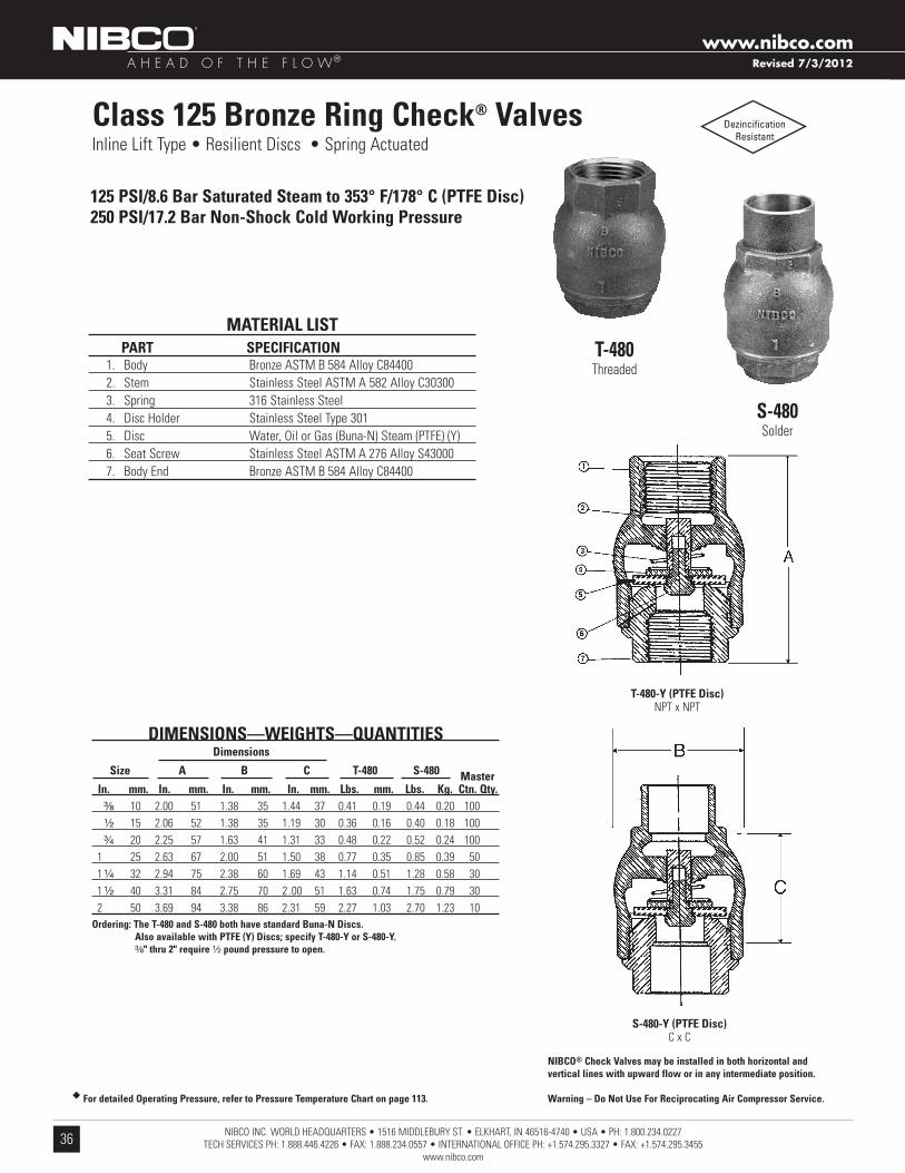
Class 125 Bronze Ring Check® Valves Inline Lift Type • Resilient Discs • Spring Actuated
125 PSI/8 .6 Bar Saturated Steam to 353° F/178° C (PTFE Disc)250 PSI/17 .2 Bar Non-Shock Cold Working Pressure
T-480Threaded
S-480Solder
T-480-Y (PTFE Disc)NPT x NPT
S-480-Y (PTFE Disc)C x C
DIMENSIONS—WEIGHTS—QUANTITIES Dimensions
Size A B C T-480 S-480 Master In . mm . In . mm . In . mm . In . mm . Lbs . mm . Lbs . Kg . Ctn . Qty . ³⁄₈ 10 2.00 51 1.38 35 1.44 37 0.41 0.19 0.44 0.20 100 ¹⁄₂ 15 2.06 52 1.38 35 1.19 30 0.36 0.16 0.40 0.18 100 ³⁄₄ 20 2.25 57 1.63 41 1.31 33 0.48 0.22 0.52 0.24 100 1 25 2.63 67 2.00 51 1.50 38 0.77 0.35 0.85 0.39 50 1 ¹⁄₄ 32 2.94 75 2.38 60 1.69 43 1.14 0.51 1.28 0.58 30 1 ¹⁄₂ 40 3.31 84 2.75 70 2 .00 51 1.63 0.74 1.75 0.79 30 2 50 3.69 94 3.38 86 2.31 59 2.27 1.03 2.70 1.23 10Ordering: The T-480 and S-480 both have standard Buna-N Discs . Also available with PTFE (Y) Discs; specify T-480-Y or S-480-Y . ³⁄₈" thru 2" require ¹⁄₂ pound pressure to open .
MATERIAL LIST PART SPECIFICATION 1. Body Bronze ASTM B 584 Alloy C84400 2. Stem Stainless Steel ASTM A 582 Alloy C30300 3. Spring 316 Stainless Steel 4. Disc Holder Stainless Steel Type 301 5. Disc Water, Oil or Gas (Buna-N) Steam (PTFE) (Y) 6. Seat Screw Stainless Steel ASTM A 276 Alloy S43000 7. Body End Bronze ASTM B 584 Alloy C84400
DezincificationResistant
NIBCO® Check Valves may be installed in both horizontal and vertical lines with upward flow or in any intermediate position .
Warning – Do Not Use For Reciprocating Air Compressor Service .u For detailed Operating Pressure, refer to Pressure Temperature Chart on page 113 .
LMR PLUS Electric Fire Pump ControllersElectrical Wiring Schematic
For more information visit: www.chfire.com
FD30 Across-the-Line
LMRPLUS PLUS
ES05805088K/D
Electrical Wiring Schematic
May 2011
N. Y. C.APPROVED
INP
UT
#2
LO
WR
OO
MT
EM
PE
RA
TU
RE
INT
ER
LO
CK
ON
DE
LU
GE
VA
LV
E(R
EM
OV
EJ
UM
PE
RIF
US
ED
)
INP
UT
#5
INP
UT
#4
INP
UT
#3
INP
UT
#7
INP
UT
#6
INP
UT
#8
INP
UT
#9
COMMON ALARM
COMMON ALARM
PHASE FAILURE(NORMALLY ENERGIZED)
PHASE FAILURE
PHASE REVERSAL
PHASE REVERSAL
FUTURE #1
FUTURE #1
PUMP RUN
PUMP RUN
(NORMALLY ENERGIZED)
(NORMALLY ENERGIZED)
OPTION RELAY #1(2 SETS FORM-C)
OPTION RELAY #2(2 SETS FORM-C)
OPTION RELAY #4(2 SETS FORM-C)
(2 SETS FORM-C)
OPTION RELAY #7
OPTION RELAY #8
(2 SETS FORM-C)
(2 SETS FORM-C)
OPTION RELAY #6(2 SETS FORM-C)
OPTION RELAY #5(2 SETS FORM-C)
(NORMALLY ENERGIZED)
RE
MO
TE
ST
AR
T
LO
WS
UC
TIO
N
PU
MP
ST
AR
T
INP
UT
#1
OPTION RELAY #3
INP
UT
#2
ALA
RM
CO
NT
AC
TS
INT
ER
NA
LC
ON
NE
CT
ION
S
CUSTOMER INPUTS
LMR PLUS Field Connections
Electric Fire Pump Controllers
LMRPLUS PLUS
For more information visit: www.chfire.com
Field Connections
FD30 Across-the-Line
Line Terminals (Incoming Cables)
Load Terminals (To Motor)
NOTE:1. MOTOR CONNECTIONS VARY, PLEASE REFER TO SPECIFIC MOTOR CONNECTION DIAGRAM.2. PLEASE OBSERVE PROPER PHASE ROTATION, A,B,C-L1,L2,L3 AS CONTROLLER IS PHASE SENSITIVE.3. CABLE SIZE TO BE 125% OF FULL LOAD CURRENT. REFER TO WIRE SIZE TABLE IN NFPA 70.
Line Terminals on Main Isolation Switch (Incoming Cables)
LINE VOLTAGE Service Entrance GND. LUG
Qty. & Cable Sizes
September 2013
N. Y. C.APPROVED
COMMON ALARM
COMMON ALARM
PHASE FAILURE(NORMALLY ENERGIZED)
PHASE FAILURE
PHASE REVERSAL
PHASE REVERSAL
FUTURE #1
FUTURE #1
PUMP RUN
PUMP RUN
(NORMALLY ENERGIZED)
(NORMALLY ENERGIZED)
(NORMALLY ENERGIZED)
AL
AR
MC
ON
TA
CT
S
For ambient temperatures above 30C (86F), the temperature rating of motor conductors is recommended to be a minimum of 90C (194F)For Proper Cable Size Refer to National Electrical Code NFPA-70
200-208 220-240 380-415 440-480 550-600 Single Run Double Run
10 10 15 20 25 (1) #14 - #8 PER (CU/AL) (2) #14 - #8 PER (CU/AL)
20 25 30 50 60 (1) #14 - #1 PER (CU/AL) (2) #14 - #2 PER (CU/AL)
40 60 75 125 100 (1) #8 - 3/0 PER (CU/AL) (2) #8 - 2/0 PER (CU/AL)
75 100 150 200 200 (1) #2 - 750MCM PER (CU/AL) (2) 1/0 - 250MCM PER (CU/AL)
150 200 300 400 500 (1) 1/0 - 500MCM PER (CU/AL) (2) 1/0 - 500MCM PER (CU/AL)
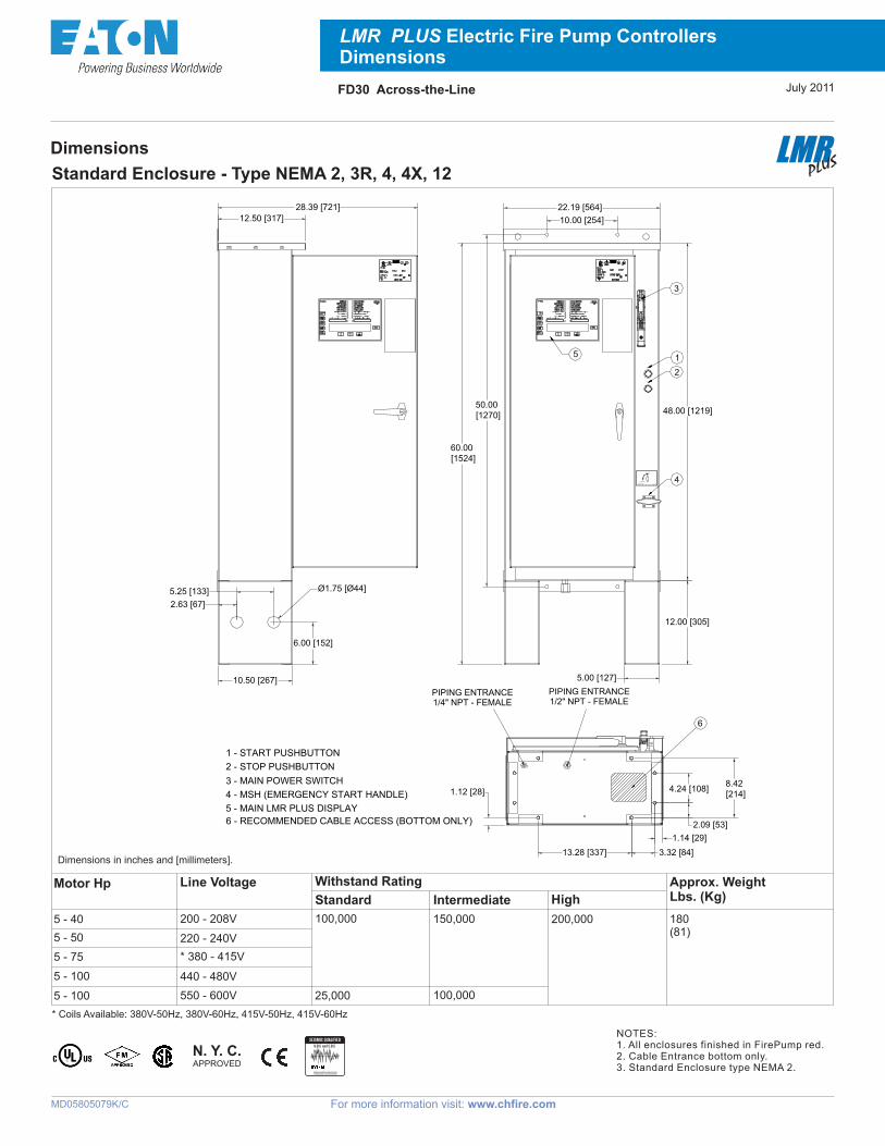
NOTES:1. All enclosures finished in FirePump red.2. Cable Entrance bottom only.3. Standard Enclosure type NEMA 2.
N. Y. C.APPROVED
July 2011
U.B.C and C.B.C
Must Be Installed Per Applicable Codeand Manufacturers Recommendations
SEISMIC QUALIFIED
12.50 [317]
28.39 [721]
10.50 [267]
6.00 [152]
5.25 [133]
2.63 [67]
60.00 [1524]
5.00 [127]
12.00 [305]
48.00 [1219]
22.19 [564]
10.00 [254]
50.00 [1270]
1.12 [28]
PIPING ENTRANCE1/2" NPT - FEMALE
8.42 [214]
3.32 [84]
2.09 [53]
13.28 [337]
4.24 [108]
1.14 [29]
6
PIPING ENTRANCE1/4" NPT - FEMALE
STOP
START
1 - START PUSHBUTTON
2 - STOP PUSHBUTTON
3 - MAIN POWER SWITCH
4 - MSH (EMERGENCY START HANDLE)
5 - MAIN LMR PLUS DISPLAY
6 - RECOMMENDED CABLE ACCESS (BOTTOM ONLY)
Ø1.75 [Ø44]
3A13357H01 3A13357H01
For more information visit: www.chfire.com
Main Display - LMR Plus Fire Pump Controllers
LMRPLUS PLUS
MD05805096K/D
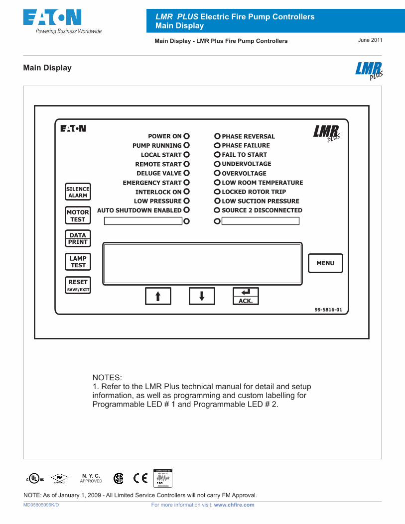
Main Display
LMR PLUS Electric Fire Pump Controllers Main Display
NOTES:1. Refer to the LMR Plus technical manual for detail and setup information, as well as programming and custom labelling for Programmable LED # 1 and Programmable LED # 2.
NOTE: As of January 1, 2009 - All Limited Service Controllers will not carry FM Approval.
June 2011
N. Y. C.APPROVED
POWER ON
PUMP RUNNING
LOCAL START
REMOTE START
DELUGE VALVE
EMERGENCY START
INTERLOCK ON
LOW PRESSURE
AUTO SHUTDOWN ENABLED
PHASE REVERSAL
PHASE FAILURE
FAIL TO START
UNDERVOLTAGE
OVERVOLTAGE
LOW ROOM TEMPERATURE
LOCKED ROTOR TRIP
LOW SUCTION PRESSURE
SOURCE 2 DISCONNECTED
LMRPLUS
ACK.
MENU
SAVE/EXIT
DATAPRINT
LAMPTEST
RESET
MOTORTEST
SILENCEALARM
99-5816-01
U.B.C and C.B.C
Must Be Installed Per Applicable Codeand Manufacturers Recommendations
SEISMIC QUALIFIED
Multi-Sense® Model 231 Wet-to-Wet, Differential, Multi-Configurable Pressure Transducer
FEATURES■ Field Selectable Output - True 4 to 20 mA, 0 to
5, 1 to 5, and 0 to 10 VDC
■ Field Selectable Pressure Ranges
■ Field Accessible Push-Button Zero and Re-mote Zero
■ Dual Sensors
■ Optional 3- or 5-Valve Manifold
■ Hinged Cover
■ Field Selectable Port Swap
■ Optional LCD Display ■ All Cast Aluminum, NEMA4 Rated Housing■ CE and RoHS Compliant
APPLICATIONS■ Energy Management Systems
■ Process Control Systems
■ Flow Measurement of Various Gases or Liq-uids
■ Liquid Level Measurement of Pressurized Vessels
■ Pressure Drop Across Filters
NOTE: Setra quality standards are based on AN-SI-Z540-1. The calibration of this product is NIST traceable.U.S. Patent nos. 6019002; 6014800
DESCRIPTIONSetra’s Model 231 Multi-Sense Wet-to-Wet differential pres-sure transducer all-inclusive design provides users with field accessible ranging, choice of output and field zeroing.
Choose from three configurable pressure transducers: 5 up to 50 psid, 10 up to 100 psid, or 25 up to 250 psid. Each Model 231 has 4 unidirectional and 4 bidirectional switch selectable pressure ranges and can be reconfigured in the field for 0-5 VDC, 1-5 VDC, -0-10 VDC, or 4 to 20 mA output. The Model 231 jumper selectable port swap feature eliminates costly replumbing if the pressure transducer is improperly installed or replaced. An optional LCD display is available for on-site indication of line and differential pressure.
SPECIFICATIONSElectrical Data (Voltage) Performance Data Environmental Data
Circuit 3-Wire Accuracy RSS1 (at constant temp.) Operating3 Temperature °F (°C) -4 to +185 (-20 to -85)
Excitation15 to 30 VDC/18 to 30 VAC (Reverse Excitation Protected)
Pressure Ranges A, B, C ±1.0% FS Storage Temperature °F (°C) -4 to +185 (-20 to +85)
Output4 0 to 5 VDC, 0 to 10 VDC, 1 to 5 VDC Pressure Ranges D ±2.0% FS Vibration 10g from 50Hz to 2000 Hz
Output5 4 to 20 mA Pressure Media Size 4.0 x 6 x 2 in. (102 x 152 x 51 mm)
External Load 0 to 250 OhmsLiquids or Gases Compatible with 17-4 PH Stainless SteelNote: Hydrogen not recommended for use with 17-4 PH stainless steel
Weight 1.5 lb
Min. Supply Voltage (VDC) 15 + 0.02 x (Resistance of reciever plus line).1 RSS of Non-Linearity, Hysteresis, and Non-Repeatability.2 Units calibrated at nominal 70˚F. Maximum thermal error computed from this datum. 3 Operating temperature limits of the electronics only. Pressure media temperatures may be considerably higher or lower.
4 Calibrated into a 50K ohm load, operable into a 5000 ohm load or greater. 5 Calibrated at factory with a 24 VDC loop supply voltage and a 250 ohm load. Specifications subject to change without notice.
Sensor Vacity Volume 0.2 cc
Max. Supply Voltage (VDC) 30 + 0.004(Resistance of reciever plus line). Thermal Effects2
Compensated Range °F (°C) +32 to +130 (0 to +54)
Zero/Span Shift %FS/100°F (50°C) 2.0 (1.8)
Warm-up Shift <0.12% FS
Response Time 1 to 5 sec. (selectable)
Proof Pressure 2 x Full Scale
Burst Pressure 15 x Full Scale (50 psi), 10 x Full Scale (75 x 150 psi), 8 x Full Scale (250 psi)1
Multi-Sense® Model 231 Wet-to-Wet, Differential, Multi-Configurable Pressure Transducer
V1 V2
V3
3-Valve Manifold Assembly Description
MODEL 230 DIFFERENTIAL PRESSURE
TRANSDUCER
V1 V2
V3
(Order as Pressure Code Fitting "3V".)
Manifold Block BrassValves (3) V1 for connection to +port V2 for connection to -port V3 for equalizing pressureValve type 90 Degree On/Off
Process Connections 1/4” -18 NPT Internal Thread
MODEL 230 DIFFERENTIAL PRESSURE
TRANSDUCER
HIGH PROCESS CONNECTION 1/4'' NPT
LOW PROCESS CONNEC-TION 1/4'' NPT
SHUT OFF VALVES
SHUNT VALVES
Low Process/Com-mission 1/4”NPT Connection
V6 V7
V4 V5
V1 V2
High Process Connection1/4”NPT
Low Process Connection1/4”NPT
V3
Model 230Differential Pressure Transducer
SHUT OFF VALVES
SHUNT VALVE
Manifold Block BrassValves (5) V1 for connection to ±port V2 for connection to -port V3 for equalizing pressure V4 for connection to external gauge or alternate plumbing configuration V5 for connection to external gauge or alternate plumbing configurationValve Type 90 Degree On/OffProcess Connection 1/4 ”-18 NPT Internal Thread
5-Valve Manifold Assembly Description (Order as Pressure Code Fitting “5V”.)
4.00102
.3 810
.3 1
8
7.21183
8.88226
2.1454
2.0051
2.0051
2.1454
For differential pressure measurements at high line pressure (250 psig max), it is recommended that the pressure sensor be installed with a valve in each line, plus a shunt valve across the high and low (reference) pressure ports as shown.
Opt. 3V 3-V Manifold assembled w/ Model 231 Opt. D LCD Display
Opt. 5V 5-V Manifold assembled w/ Model 231
2 3 1 G
Multi-Sense® Model 231 Wet-to-Wet, Differential, Multi-Configurable Pressure Transducer
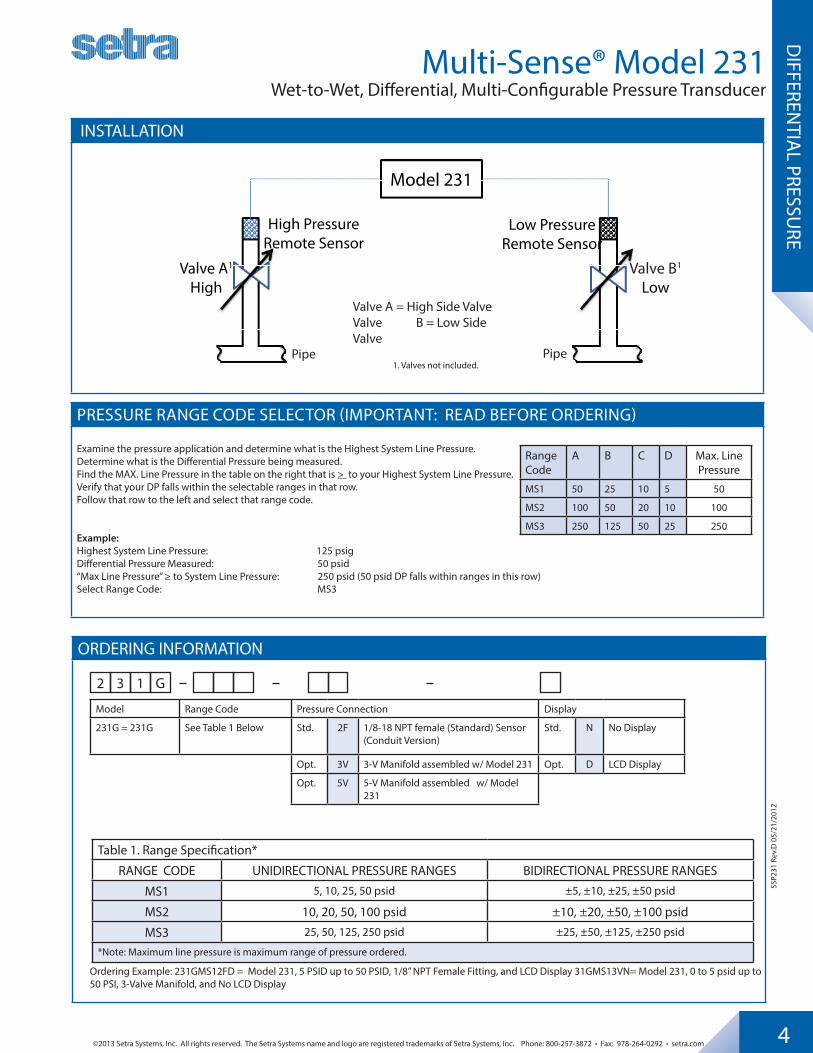
INSTALLATION
Valve A1
High
Low Pressure Remote Sensor
High Pressure Remote Sensor
Valve B1
Low
Model 231
Valve A = High Side ValveValve B = Low Side Valve
1. Valves not included.
PRESSURE RANGE CODE SELECTOR (IMPORTANT: READ BEFORE ORDERING)
Examine the pressure application and determine what is the Highest System Line Pressure. Determine what is the Differential Pressure being measured.Find the MAX. Line Pressure in the table on the right that is > to your Highest System Line Pressure.Verify that your DP falls within the selectable ranges in that row.Follow that row to the left and select that range code.
Example: Highest System Line Pressure: 125 psigDifferential Pressure Measured: 50 psid“Max Line Pressure” ≥ to System Line Pressure: 250 psid (50 psid DP falls within ranges in this row)Select Range Code: MS3
Range Code
A B C D Max. Line Pressure
MS1 50 25 10 5 50
MS2 100 50 20 10 100
MS3 250 125 50 25 250
PipePipe
SSP2
31 R
ev.D
05/
21/2
012
Ordering Example: 231GMS12FD = Model 231, 5 PSID up to 50 PSID, 1/8” NPT Female Fitting, and LCD Display 31GMS13VN= Model 231, 0 to 5 psid up to 50 PSI, 3-Valve Manifold, and No LCD Display
• Patented PowerFlex™ movement with polyester segment
• True Zero™ indication, a unique safety featureAshcroft® fire protection sprinkler
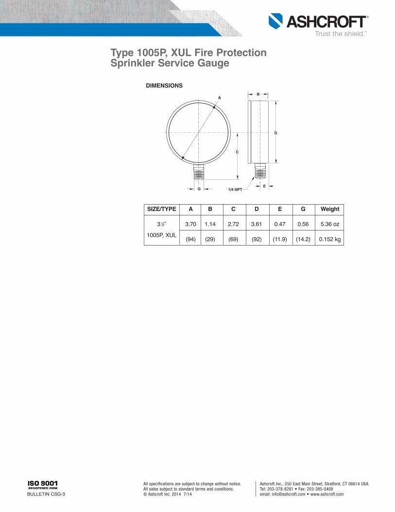
gauges are Underwriters Laboratory listed and Factory Mutual approved forfire protection sprinkler service. The casematerial on Type 1005P, XUL gauges isABS. The 0-300 psi pressure range isused on “wet” systems where water isavailable to the sprinkler heads. The 0-80retard to 250 psi pressure range is usedon dry systems where the lines are filledwith air pressure until system activation.The 0-600 psi gauge is available for sys-tems requiring higher pressures.Due to global demands for fire protec-
tion sprinkler gauges, Ashcroft offers ULlisted, triple scale (bar, kPa, psi) dialgauges. The patented PowerFlex™ movement
with polyester segment is designed toprovide unequalled shock and vibrationresistance resulting in superior perform-ance and extended gauge life.True Zero™ indication, a standard
feature on these gauges, reduces thepotential risk of installing a damagedgauge on your equipment.
PRODUCT SPECIFICATIONSAshcroft®Model No.: 1005P, XULAccuracy: ASME B 40.100
Grade B (±3-2-3% of span)Size: 31/2˝Case: ABS (Polycarbonate blend)Ring: NoneWindow: Polycarbonate, push-in Dial: Black figures on white back-
groundPointer: Black, aluminumBourdon tube: “C” shaped bronzeMovement: Patented PowerFlex™ with
polyester segment Socket: BrassRestrictor: NoneConnection: 1⁄4 NPT lowerRanges: Single, dual or triple scale
0-300 psi (water)0-80 retard to 250 psi (air)0-600 psi
Operatingtemperature: –40°F to 150°F; –40°C to 65°C UL 393 Listed, UL of Canada Listed and FMapproved. Equivalent (single or dual scale) metricscales are available
OPTIONAL FEATURESCustomized dialsOther UL listed ranges on applicationBlack Rubber Gauge Boot
Type 1005P, XUL Fire Protection Sprinkler Service Gauge
HOW TO ORDER (Typical example) 35 W 1005 P H 02L XUL 300#Dial Size: 31/2˝Movement: Patented PowerFlex™
Case Type Number: 1005PCase Material: ABSSocket Material: BrassConnection Size/Location: 1/4 NPT LowerListing: UL listed, FM approvedRange: 0/300 psi
Ashcroft Inc., 250 East Main Street, Stratford, CT 06614 USATel: 203-378-8281 • Fax: 203-385-0408email: [email protected] • www.ashcroft.com
July 2011 For more information visit: www.chfire.com PS05805008K/E
Fire Pump Controllers 1-1 Features
Typical Specifications 1. Approvals
A. The Fire Pump Controller shall meet the require-ments of the latest edition of NFPA 20 and shall be listed by [Underwriters Laboratories (UL)]and ap-proved by [Factory Mutual Research (FM)] [Cana-dian Standards Association (CSA)] [New York De-partment of Buildings (NYSB)] and carry the CE marking for fire pump service.
2. Starting Type A. The controller shall be of the combined manual and
automatic type designed for [Full Voltage Starting] [Part Winding Starting] [Primary Resistor Starting] [Autotransformer Starting] [Wye-Delta (Star-Delta) Open Transition Starting] [Wye-Delta (Star-Delta) Closed Transition Starting] [Solid State Soft Start Starting]
3. Ratings A. The Controller shall have a withstand rating of
4. Construction A. The controller shall include a motor rated combina-
tion isolating switch and circuit breaker, mechanically interlocked and operated with a single externally mounted handle.
B. The isolating switch shall be rated to disconnect the motor load.
C. The isolating switch/circuit breaker combination shall be mechanically interlocked such that the enclosure door cannot be opened when the handle is in the on position except by a tool operated defeater mechan-ism.
D. The controller manufacturer shall manufacture the contactor, isolating switch, circuit breaker, pushbut-tons, and enclosures. Brand-labeled components will not be accepted.
5. Enclosure A. The controller shall be housed in a NEMA Type 2
B. Optional Enclosures: 1. NEMA 3R (IEC IP14) rain-tight enclosure. 2. NEMA 4 (IEC IP66) watertight enclosure. 3. NEMA 4X (IEC IP66) watertight 304 stainless
steel enclosure. 4. NEMA 4X (IEC IP66) watertight 316 stainless
steel enclosure. 5. NEMA 4X (IEC IP66) watertight corrosion resis-
tant enclosure. 6. NEMA 12 (IEC IP52) dust-tight enclosure.
6. Microprocessor Control A. The controller shall come complete with a 4 line by
40 character LCD display mounted on a panel open-ing in the front door. The LCD display shall indicate the following: 1. Main screen displaying system pressure, three-
phase voltage and amperage readings, system frequency, date, and time.
2. Set point review screen displaying the pro-grammed pressure start and stop points, and weekly test time.
3. Controller statistics screen, including: a. Powered Time b. Motor Run Time c. Number of Calls to Start d. Number of Starts e. Last Motor Start Time f. Last Motor Run Time g. Last Low Pressure Start h. Minimum System Voltage i. Maximum System Voltage j. Minimum System Frequency k. Maximum System Frequency l. Minimum System Pressure m. Maximum System Pressure n. Last System Startup o. Last Phase Failure p. Last Phase Reversal q. Last Locked Rotor Trip r. Maximum Run Current s. Last Locked Rotor Current
4. Controller diagnostics screen, including: a. Date & Time b. Firmware Version c. Shop Order Number d. Customer Order Number e. Transformer Output Voltage f. Current Transformer Outputs g. Pressure Transducer Calibrated Settings h. Input Status i. Output Status
5. Display last messages screen that will display up to 10,000 alarms/messages stored in the controllers' memory.
6. Display up to ten (10) custom messages of up to 100 characters each, which will continually scroll across the fourth line of the display.
7. Remaining time left on active timers. B. The controller shall be supplied with ten (10) green
status LED’s for the following: 1. Power On 2. Pump Running 3. Local Start 4. Remote Start 5. Deluge Valve 6. Emergency Start
LMR Plus Electric Fire Pump Controllers
July 2011 For more information visit: www.chfire.com PS05805008K/E
Fire Pump Controllers 1-2 Features
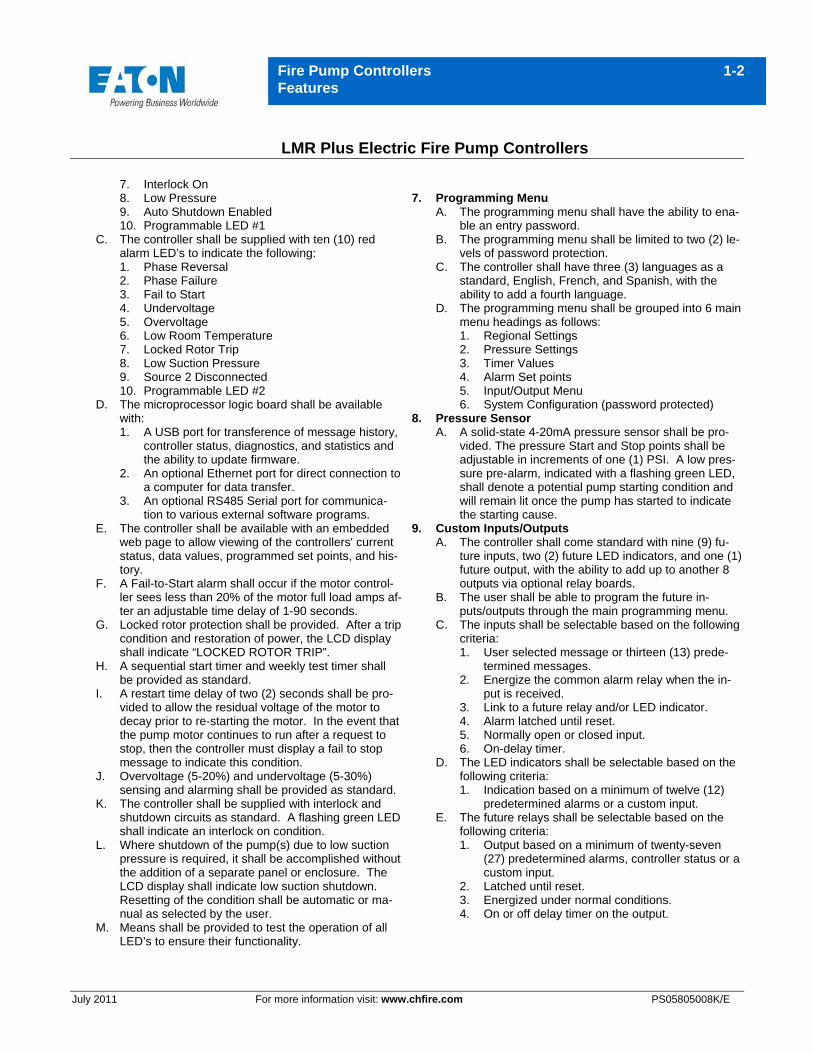
7. Interlock On 8. Low Pressure 9. Auto Shutdown Enabled 10. Programmable LED #1
C. The controller shall be supplied with ten (10) red alarm LED’s to indicate the following: 1. Phase Reversal 2. Phase Failure 3. Fail to Start 4. Undervoltage 5. Overvoltage 6. Low Room Temperature 7. Locked Rotor Trip 8. Low Suction Pressure 9. Source 2 Disconnected 10. Programmable LED #2
D. The microprocessor logic board shall be available with: 1. A USB port for transference of message history,
controller status, diagnostics, and statistics and the ability to update firmware.
2. An optional Ethernet port for direct connection to a computer for data transfer.
3. An optional RS485 Serial port for communica-tion to various external software programs.
E. The controller shall be available with an embedded web page to allow viewing of the controllers' current status, data values, programmed set points, and his-tory.
F. A Fail-to-Start alarm shall occur if the motor control-ler sees less than 20% of the motor full load amps af-ter an adjustable time delay of 1-90 seconds.
G. Locked rotor protection shall be provided. After a trip condition and restoration of power, the LCD display shall indicate “LOCKED ROTOR TRIP”.
H. A sequential start timer and weekly test timer shall be provided as standard.
I. A restart time delay of two (2) seconds shall be pro-vided to allow the residual voltage of the motor to decay prior to re-starting the motor. In the event that the pump motor continues to run after a request to stop, then the controller must display a fail to stop message to indicate this condition.
J. Overvoltage (5-20%) and undervoltage (5-30%) sensing and alarming shall be provided as standard.
K. The controller shall be supplied with interlock and shutdown circuits as standard. A flashing green LED shall indicate an interlock on condition.
L. Where shutdown of the pump(s) due to low suction pressure is required, it shall be accomplished without the addition of a separate panel or enclosure. The LCD display shall indicate low suction shutdown. Resetting of the condition shall be automatic or ma-nual as selected by the user.
M. Means shall be provided to test the operation of all LED’s to ensure their functionality.
7. Programming Menu
A. The programming menu shall have the ability to ena-ble an entry password.
B. The programming menu shall be limited to two (2) le-vels of password protection.
C. The controller shall have three (3) languages as a standard, English, French, and Spanish, with the ability to add a fourth language.
D. The programming menu shall be grouped into 6 main menu headings as follows: 1. Regional Settings 2. Pressure Settings 3. Timer Values 4. Alarm Set points 5. Input/Output Menu 6. System Configuration (password protected)
8. Pressure Sensor A. A solid-state 4-20mA pressure sensor shall be pro-
vided. The pressure Start and Stop points shall be adjustable in increments of one (1) PSI. A low pres-sure pre-alarm, indicated with a flashing green LED, shall denote a potential pump starting condition and will remain lit once the pump has started to indicate the starting cause.
9. Custom Inputs/Outputs A. The controller shall come standard with nine (9) fu-
ture inputs, two (2) future LED indicators, and one (1) future output, with the ability to add up to another 8 outputs via optional relay boards.
B. The user shall be able to program the future in-puts/outputs through the main programming menu.
C. The inputs shall be selectable based on the following criteria: 1. User selected message or thirteen (13) prede-
termined messages. 2. Energize the common alarm relay when the in-
put is received. 3. Link to a future relay and/or LED indicator. 4. Alarm latched until reset. 5. Normally open or closed input. 6. On-delay timer.
D. The LED indicators shall be selectable based on the following criteria: 1. Indication based on a minimum of twelve (12)
predetermined alarms or a custom input. E. The future relays shall be selectable based on the
following criteria: 1. Output based on a minimum of twenty-seven
(27) predetermined alarms, controller status or a custom input.
2. Latched until reset. 3. Energized under normal conditions. 4. On or off delay timer on the output.
LMR Plus Electric Fire Pump Controllers
July 2011 For more information visit: www.chfire.com PS05805008K/E
Fire Pump Controllers 1-3 Features
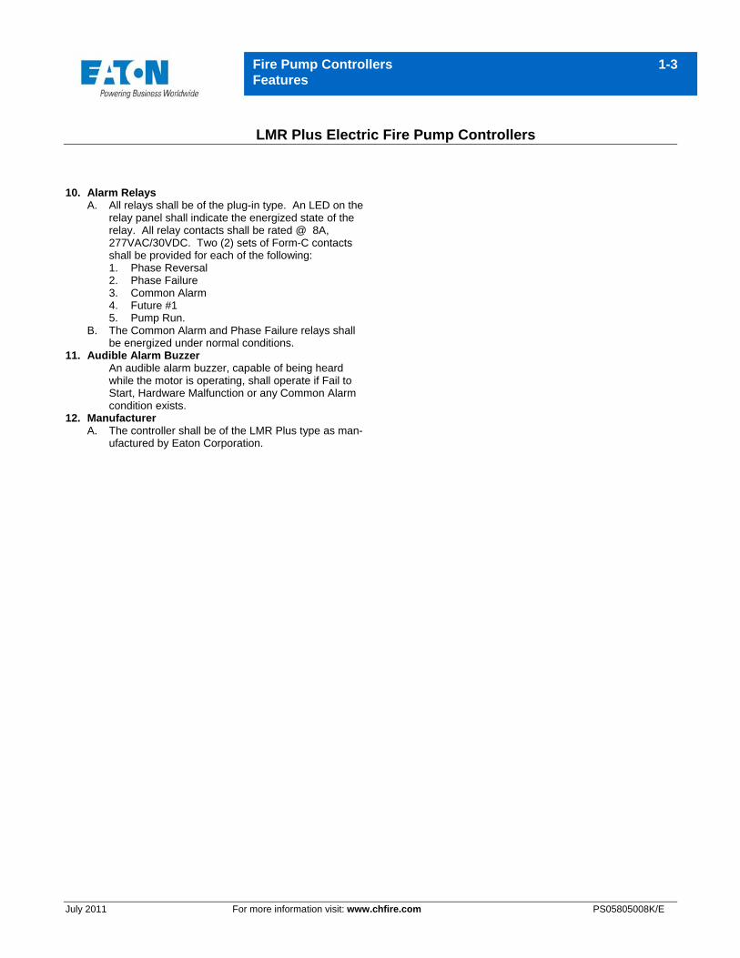
10. Alarm Relays A. All relays shall be of the plug-in type. An LED on the
relay panel shall indicate the energized state of the relay. All relay contacts shall be rated @ 8A, 277VAC/30VDC. Two (2) sets of Form-C contacts shall be provided for each of the following: 1. Phase Reversal 2. Phase Failure 3. Common Alarm 4. Future #1 5. Pump Run.
B. The Common Alarm and Phase Failure relays shall be energized under normal conditions.
11. Audible Alarm Buzzer An audible alarm buzzer, capable of being heard while the motor is operating, shall operate if Fail to Start, Hardware Malfunction or any Common Alarm condition exists.
12. Manufacturer A. The controller shall be of the LMR Plus type as man-
ufactured by Eaton Corporation.
A H E A D O F T H E F L O W®www.nibco.com
NIBCO INC. WORLD HEADQUARTERS • 1516 MIDDLEBURY ST. • ELKHART, IN 46516-4740 • USA • PH: 1.800.234.0227 TECH SERVICES PH: 1.888.446.4226 • FAX: 1.888.234.0557 • INTERNATIONAL OFFICE PH: +1.574.295.3327 • FAX: +1.574.295.3455