43
Prof. Sahil B. Sheth Department of Mechanical Engineering Alpha College of Engg & Tech. CHAPTERE-6 PRESSES & PRESS WORK
| Date post: | 21-Oct-2015 |
| Category: |
Documents |
| Upload: | sahil-sheth |
| View: | 50 times |
| Download: | 4 times |
Prof. Sahil B. ShethDepartment of Mechanical Engineering
Alpha College of Engg & Tech.
CHAPTERE-6PRESSES & PRESS WORK

34/2
IntroductionPress working is a Chipless mfg. process, which is used to form sheet metal parts.
Material thickness : upto 1 mm = Foil (Aluminum foils for Food packaging)
1 to 5 mm = sheet metal
above 5 mm = plate
It’s a Cold working process & Also called Cold stamping.
Plastic deformation takes place at room temp.
Merits & DemeritsFastest & most efficient way to form parts from sheetmetal in mass production.
Unique parts can b made.
New tool sets are needed for every dissimilar part.
Materials & ApplicationsLow carbon steel ( 0.05-0.15 % C ) is used mostly as sheetmetal bcoz of low cost, good strength & good formability(Cold work).
Aluminum & Titanium are used as sheetmetal for Aircraft & Aerospace, weight)
Aluminum & Stainless steel are used for Automobile bodies, Cold-drink canes.
G.I. sheets are used for making Roofs, Cabinets, Kitchen appliances etc

34/3
Press working/Sheetmetal Operations
The sheet metal operations done on a press may be grouped into two categories, cutting (shearing) operations and forming operations.
In cutting (shearing) operations operation, the workpiece is stressed beyond its ultimate strength.
The stresses caused in the metal by the applied forces will be shearing stresses.
The cutting operations include:
Punching (Piercing)
Blanking
Notching
Perforating
Slitting
Lancing
Shaving
Trimming

Lecture-05: Sheet Metal Forming Processes 34/4
Shearing Operations
Punching (Piercing): It is a cutting operation by which various shaped holes are made in sheet metal. Punching is similar to blanking except that in punching, the hole is the desired product, the material punched out to form the hole being waste.
Blanking: Blanking is the operation of cutting a flat shape sheet metal. The article punched out is called the blank and is the required product of the operation. The hole and metal left behind is discarded as waste.

Lecture-05: Sheet Metal Forming Processes 34/5
Notching: This is cutting operation by which metal pieces are cut from the edge of a sheet, strip or blank.
Perforating: This is a process by which multiple holes which are very small and close together are cut in flat work material.
Slitting: It refers to the operation of making incomplete holes in a workpiece.
Lancing: This is a cutting operation in which a hole is partially cut and then one side is bent down to form a sort of tab. Since no metal is actually removed, there will be no scrap.
Parting: Parting involves cutting a sheet metal strip by a punch with two cutting edges that match the opposite sides of the blank.

Lecture-05: Sheet Metal Forming Processes 34/6
Shaving: The edge of blanked parts is generally rough, uneven and unsquare. Accurate dimensions of the part are obtained by removing a thin strip of metal along the edges.
Trimming: This operation consists of cutting unwanted excess material from the periphery of previously formed components.
Schematic illustrations of shaving on a sheared edge.
(a) Shaving a sheared edge.
(b) Shearing and shaving, combined in one stroke.
Classification of Presses
According to the Power source :
1) Manually operated---Hand, ball or fly press →For thin sheetmetal work
Single sided Fly press &
Double sided Fly press
2) Power press----Mechanical, Hydraulic press etc → Heavy production work
34/7

34/8
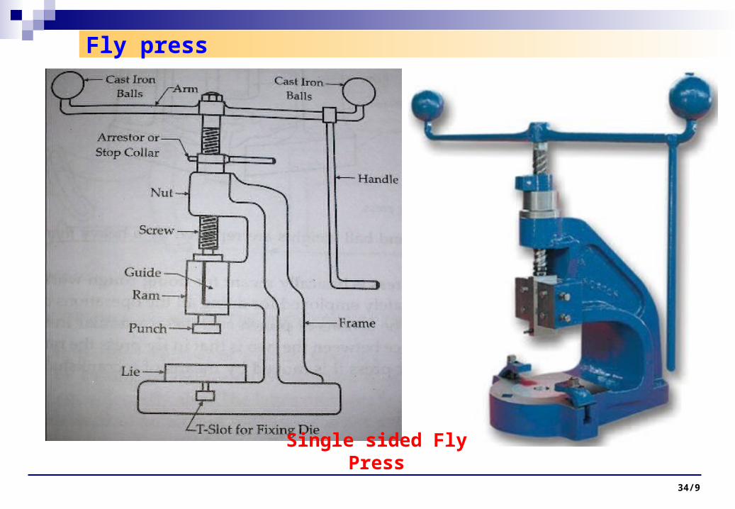
Fly press
Single sided Fly Press
Robust Cast iron Frame.
Top side of Frame is Nut, in which vertical Screw
rotates.
Screw is joined with Arm at the top that carries two
Cast iron Balls at both ends & also Handle.
These balls store Kinetic energy for further
downward movement of Screw.
Mid portion of Frame is Guide, in which ram works
attached at screw end.
Punch is attached at Ram end.
Die is rigidly fixed at Press platen(Bolster)
Stop collar is to adjust Ram stroke length, when
it touches the top surface of the Nut, prevents
further downward movement of Screw.
This Press is used for Rough Pressing work.
34/9
Fly press
Single sided Fly Press

34/10
Double sided Fly Press
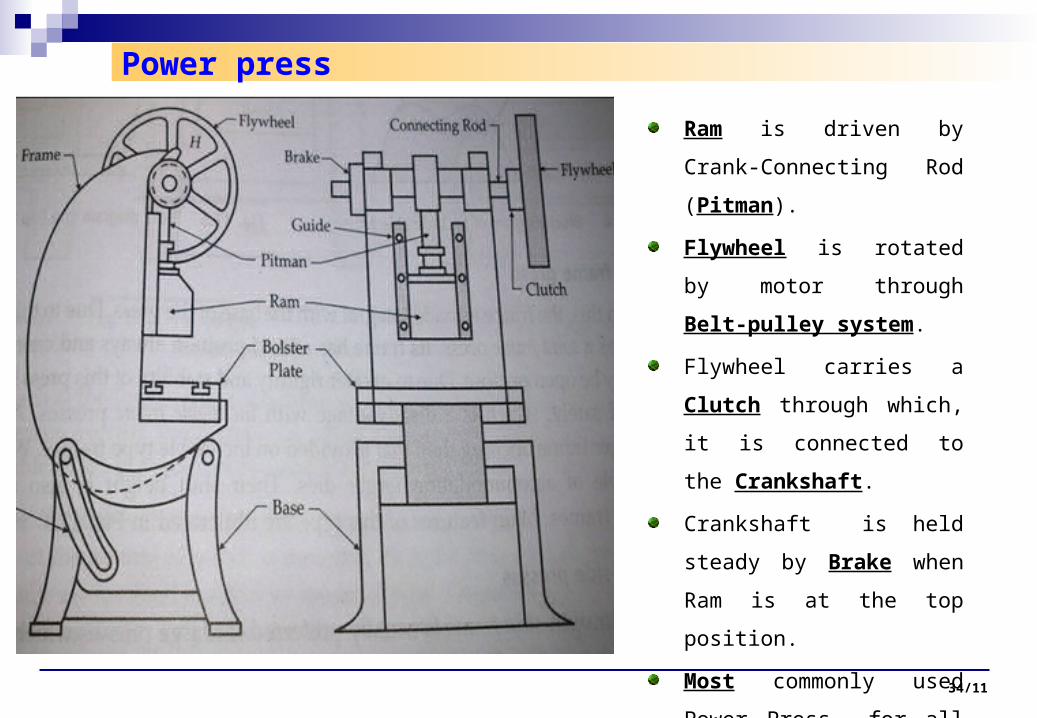
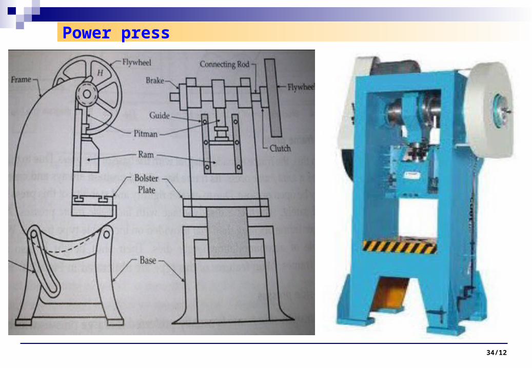
Power press
34/11
Ram is driven by Crank-
Connecting Rod (Pitman).
Flywheel is rotated by motor
through Belt-pulley system.
Flywheel carries a Clutch
through which, it is
connected to the Crankshaft.
Crankshaft is held steady by
Brake when Ram is at the
top position.
Most commonly used Power
Press for all press work.
Power press
34/12

1) Accd. To type & design of Frame :
Mostly used
Main feature is the Ability to tilt back
Can be locked in Inclined position.
Open back is for scrap removal & produced parts by Gravity.
So called OBI (open back inclinable) press
34/13
i) Inclinable frame Press ii) Gap frame Press
Frame is integral with the Base.
So called Solid /Rigid/Stable frame
Always fixed , Cant be locked Inclined .
Back may b opened/closed
Longer Bed & larger Frame opening & so can accommodate larger dies than former.
Shut height is more than former.

Used for large Presses having
large bed area & high tonnage.
Great Rigidity, longer strokes.
Has straight sides(vertical)
It consists : 1)Bed, to support
Die, 2) Vertical columns on
both sides, 3) Crown , carries
whole Press mechanism.
1) Single press unit formed by
Integrating Bed, Columns &
Crown
2) Frame has Arch shape to
give large bed area
1 2
iii) Straight side Press
.

Lecture-05: Sheet Metal Forming Processes 34/15
Straight side Press
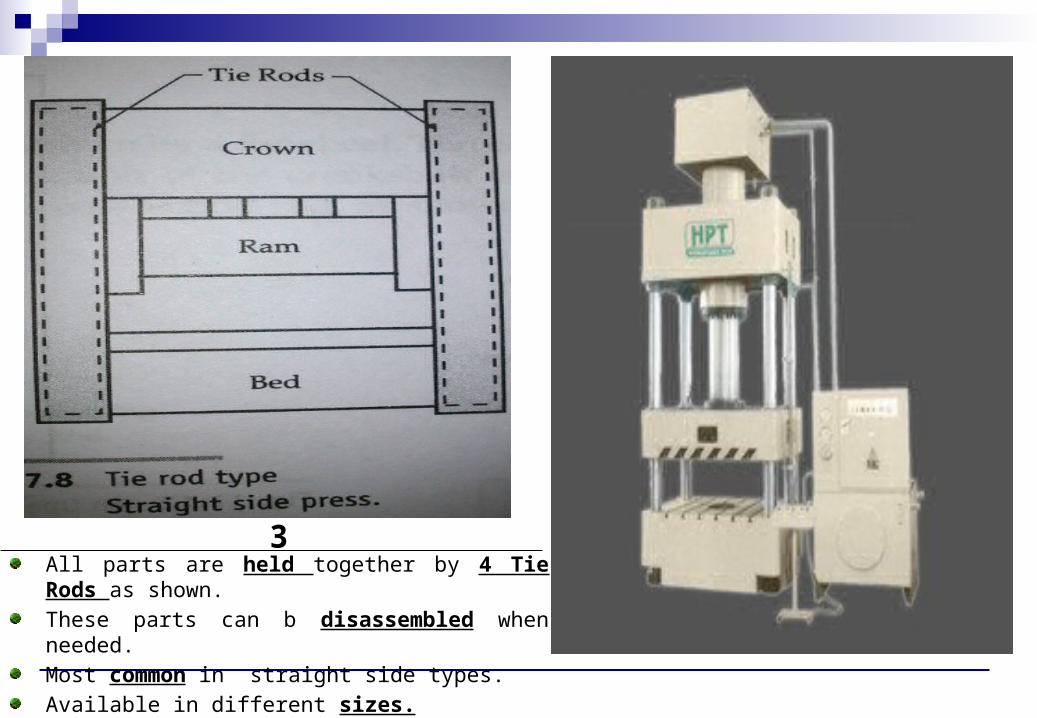
3All parts are held together by 4 Tie Rods as shown.
These parts can b disassembled when needed.
Most common in straight side types.
Available in different sizes.

34/17
Called open frame type..
Consists 4 strong Pillars, bed, Crown
These parts r fastened by Nuts
Pillars act as a Guide for Ram
4
34/18
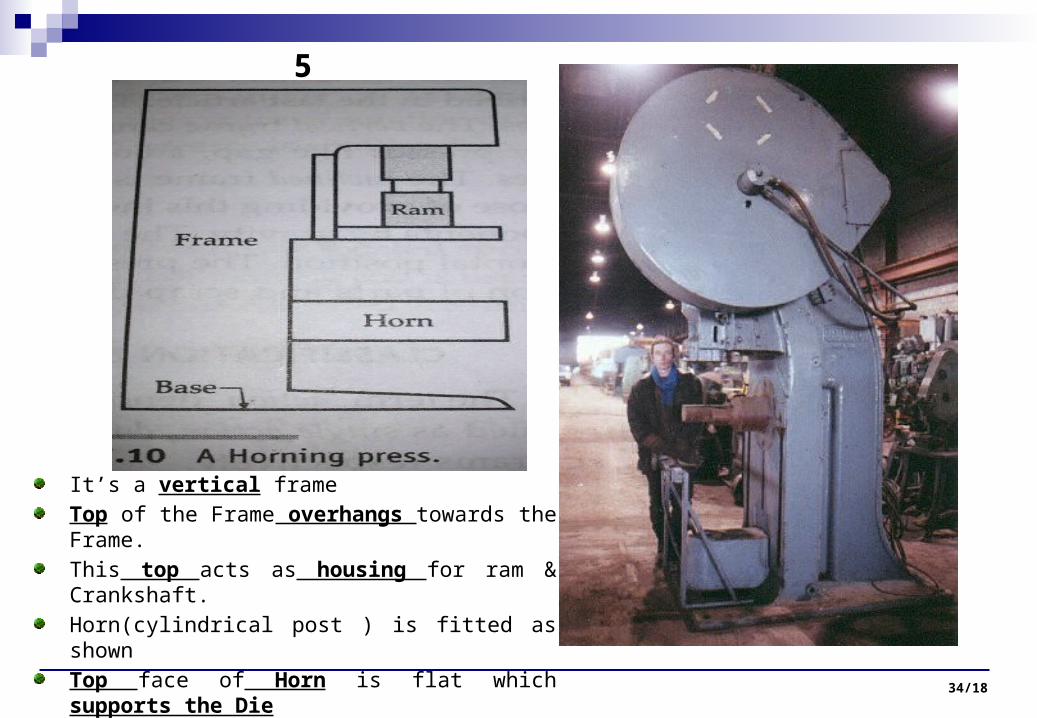
It’s a vertical frame
Top of the Frame overhangs towards the Frame.
This top acts as housing for ram & Crankshaft.
Horn(cylindrical post ) is fitted as shown
Top face of Horn is flat which supports the Die
Horn is used for Tubular work.
5

34/19
Has Knee type bed, so called Knee press.
Knee can be adjusted at desired height by screw.
So this gives variable Shut height.
Lacks rigidity, so not used for heavy work
Solid vertical frame with all sides open.
Gears & flywheel are mounted at back.
Ram works at front.
Used for light press work
6 7

2) Accd. to Frame positions
34/20
3) Accd. To Actions
Inclinable : > Frame can be inclined & adjusted at different angles
Vertical : > Frame can’t be adjusted
> It remains in vertical position only
> For examples : Gap type, Knee type, Straight side type, Open end type ,
Horning type.
Inclined : >Frame is fixed once & remains at that inclination always,
> Purpose for this inclination is to facilitate removal of Scraps & parts by Gravity.
Horizontal : > Fixed horizontal position, operation at high speed.
It denotes number of Rams on press
Single action press has single Ram
Double action press has two Rams
Tripple action press has three Rams

4) Accd. to the Mechanism of applying Power to Ram
34/21
Crankshaft is driven by flywheel & is supported in bearing
Working is same is in Power press.
Rotary motion to reciprocating motion.
Carries Eccentric drive mechanism for its Ram.
One end of Connecting rod is with eccentric housing & other is with ram.
Stroke length is smaller than Crank drive

Lecture-05: Sheet Metal Forming Processes 34/22
In Cam drive press, cam –follower are used for reciprocating action of Ram
It is spring back as in I.C. engine valve mechanism.
Very limited sizes & rarely used.
Toggle mechanism is for Double &
tripple actions presses for driving the
outer Ram.
Crankshaft drive is to drive Inner Ram.
Mostly used for large drawing Dies.
In that, mechanism actuates the blank
holder & punch is operated by crank
driven inner Ram.
This design makes maintainance &
repair easy.
Also called inverted drive
Lecture-05: Sheet Metal Forming Processes 34/23
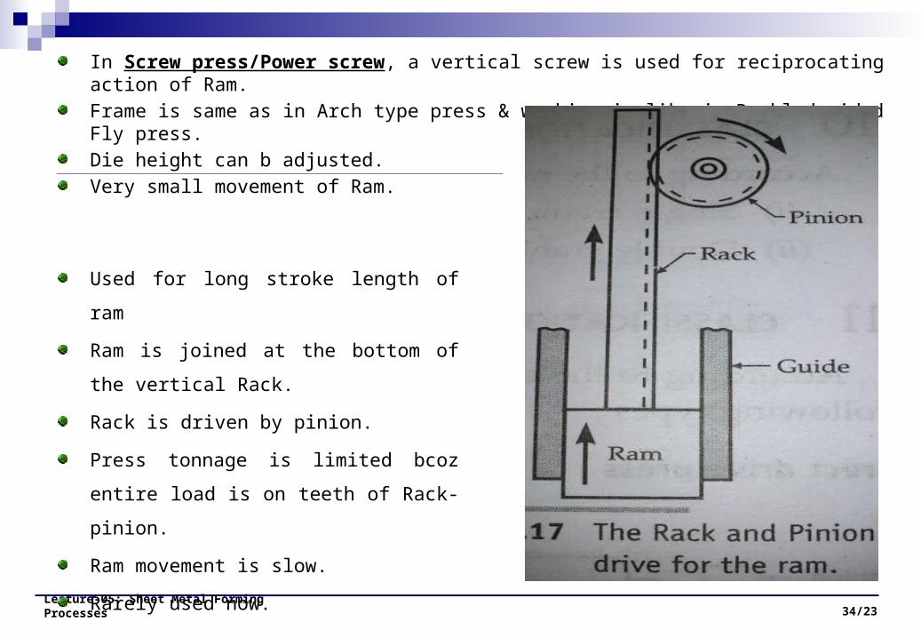
In Screw press/Power screw, a vertical screw is used for reciprocating action of Ram.
Frame is same as in Arch type press & working is like in Doubled sided Fly press.
Die height can b adjusted.
Very small movement of Ram.
Used for long stroke length of ram
Ram is joined at the bottom of the vertical
Rack.
Rack is driven by pinion.
Press tonnage is limited bcoz entire load is
on teeth of Rack-pinion.
Ram movement is slow.
Rarely used now.
Lecture-05: Sheet Metal Forming Processes 34/24
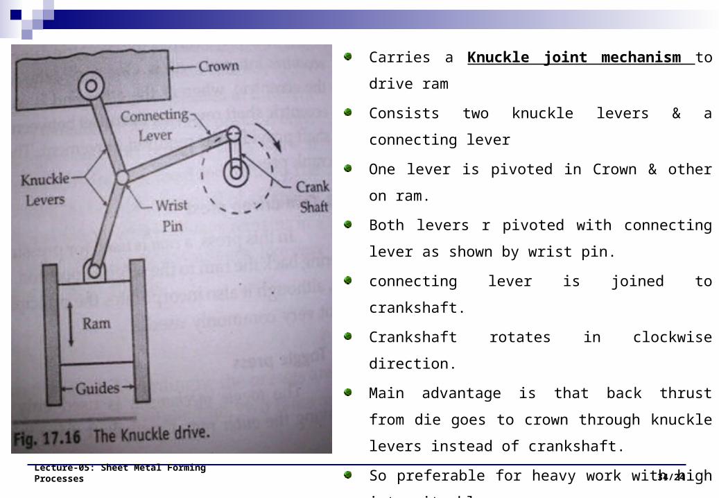
Carries a Knuckle joint mechanism to drive ram
Consists two knuckle levers & a connecting lever
One lever is pivoted in Crown & other on ram.
Both levers r pivoted with connecting lever as shown
by wrist pin.
connecting lever is joined to crankshaft.
Crankshaft rotates in clockwise direction.
Main advantage is that back thrust from die goes to
crown through knuckle levers instead of crankshaft.
So preferable for heavy work with high intensity
blow.
Coining ,extruding ,squeezing ,sizing , embossing.
Stroke length is limited

Lecture-05: Sheet Metal Forming Processes 34/25
Longer strokes than mechanical press
Blow intensity can b adjusted
Double acting piston cylinder
Ram is directly attached to piston rod.
Used for Deep drawing & other forming
operations.
More maintainance required.
5) Accd. to Number of Drive Gears
Lecture-05: Sheet Metal Forming Processes 34/26
6) Accd. to Number of Crankshafts used
Gears attatched at the crankshaft end are called Drive gears
They drive the crankshaft
Very small Presses carry only 1 Drive gear at 1 end called Single Drive.
If 1 drive gear at each end ,then called Twin drive presses
Large presses having 2 Crankshafts & each having a Twin drive ,so called Quadruple drive
press.
Single crank : 1 Crankshaft
Double crank : 2 crankshafts
7) Accd. to Power Transmission method : Motor→Crankshaft
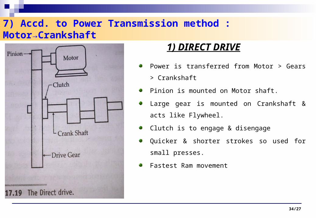
1) DIRECT DRIVE
34/27
Power is transferred from Motor > Gears > Crankshaft
Pinion is mounted on Motor shaft.
Large gear is mounted on Crankshaft & acts like
Flywheel.
Clutch is to engage & disengage
Quicker & shorter strokes so used for small presses.
Fastest Ram movement
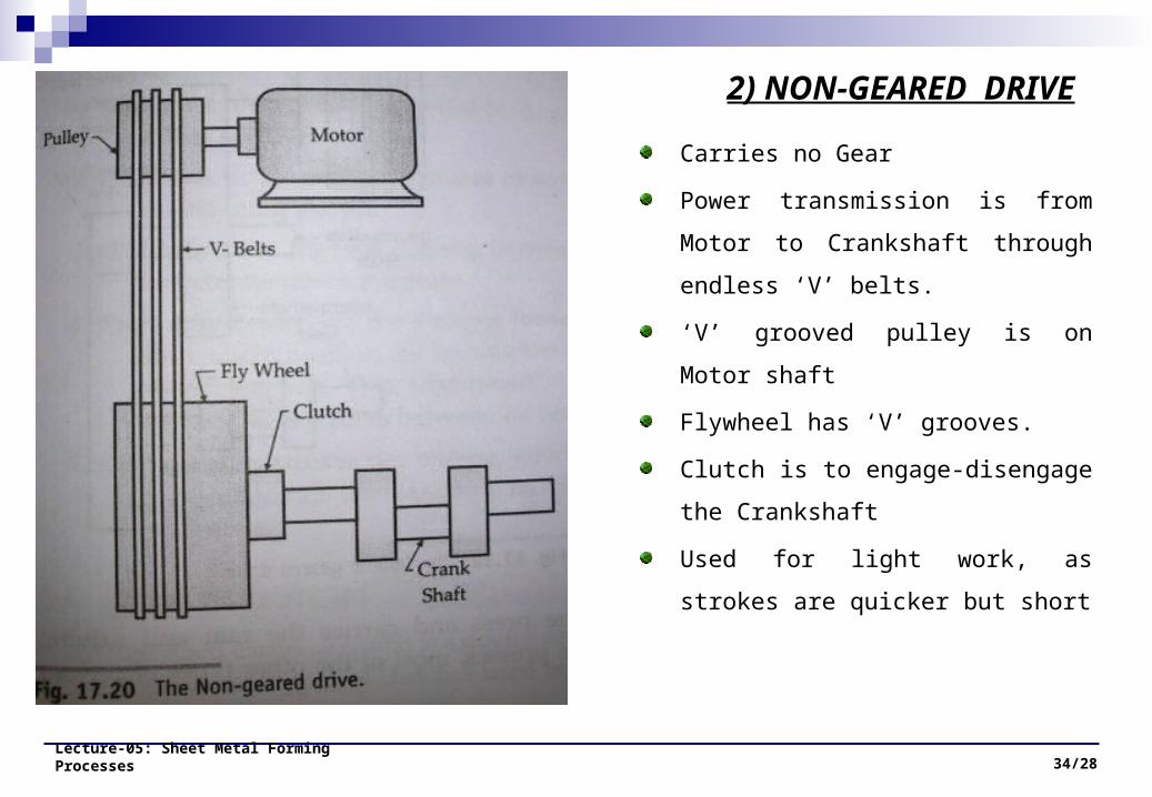
Carries no Gear
Power transmission is from Motor to
Crankshaft through endless ‘V’ belts.
‘V’ grooved pulley is on Motor shaft
Flywheel has ‘V’ grooves.
Clutch is to engage-disengage the
Crankshaft
Used for light work, as strokes are
quicker but short
Lecture-05: Sheet Metal Forming Processes 34/28
2) NON-GEARED DRIVE

Power transmission is from motor to
Counter shaft, then to Pinion-gear &
then to Crankshaft.
Can b converted to two in drive by
putting same Pinion-gear on other
sides of both shaft.
For further heavy work with long
strokes.
Lecture-05: Sheet Metal Forming Processes 34/29
3) SINGLE GEARED DRIVE

Intermediate shaft as introduced between
Flywheel shaft & Crankshaft.
Still longer strokes & high mechanical
advantage
Used for Drawing
If made two in Drive then can b used for
Forming-cutting.
Slowest Ram movement.
Lecture-05: Sheet Metal Forming Processes 34/30
4) DOUBLE GEARED DRIVE

Details of a Die set
Lecture-05: Sheet Metal Forming Processes 34/31

Classification of Dies
Single operation Dies : single operation in each Ram stroke
1) Cutting Dies : Shearing Operations
, 2) Forming Dies : Bending, Drawing & Squeezing operations
Multi operation Dies :
1) Compound Dies
2) Combination Dies
3) Progressive Dies
Lecture-05: Sheet Metal Forming Processes 34/32

Compound Dies
Lecture-05: Sheet Metal Forming Processes 34/33
Blanking & piercing operations can
be done at 1 station.
Considered as Cutting dies
Washer is made by simultaneously
Blanking & piercing operations & in 1
stroke
More accurate & economical in
mass production
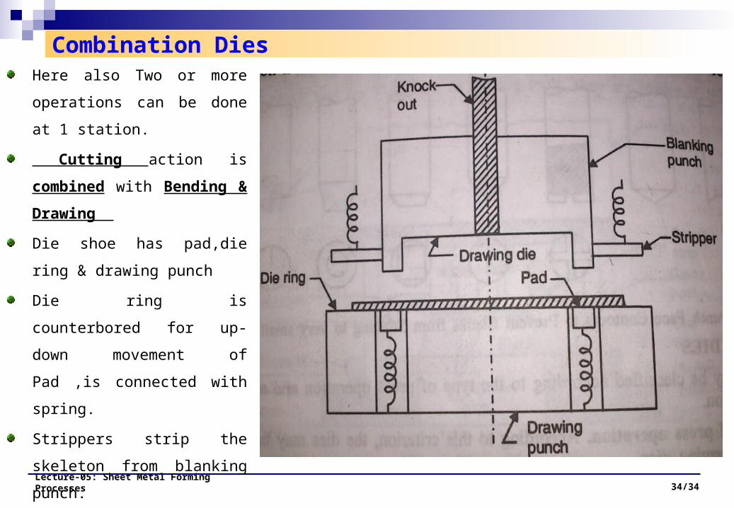
Combination Dies
Lecture-05: Sheet Metal Forming Processes 34/34
Here also Two or more
operations can be done at 1
station.
Cutting action is combined
with Bending & Drawing
Die shoe has pad,die ring &
drawing punch
Die ring is counterbored for up-
down movement of Pad ,is
connected with spring.
Strippers strip the skeleton from
blanking punch.
Knockout bar acts as ejecting
pins
Lecture-05: Sheet Metal Forming Processes 34/35
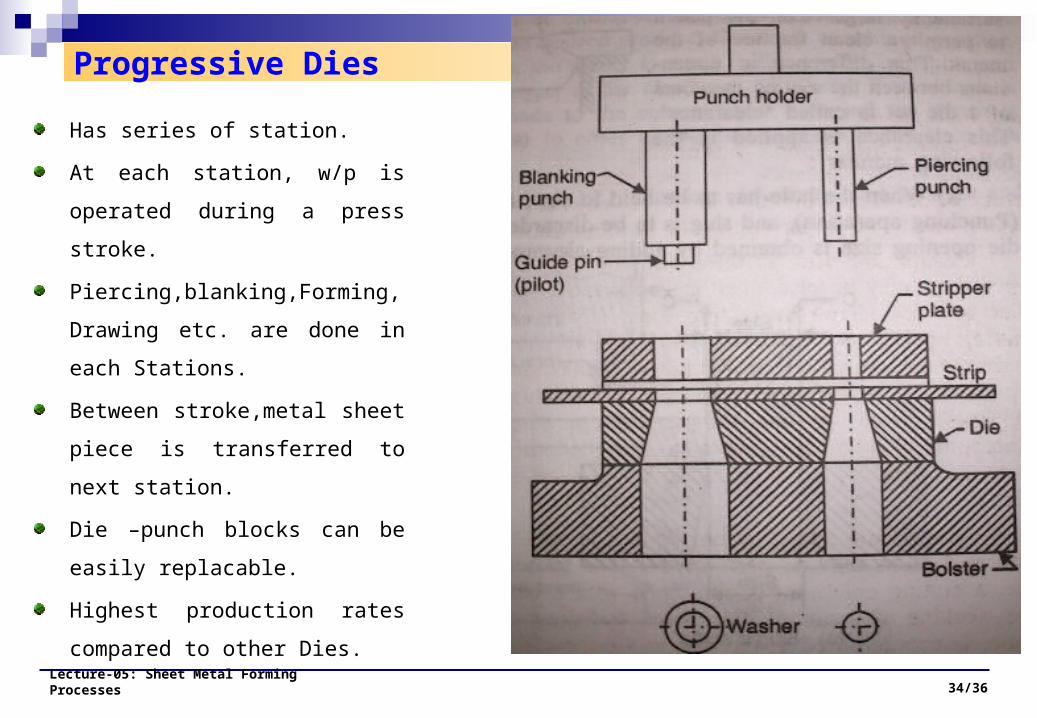
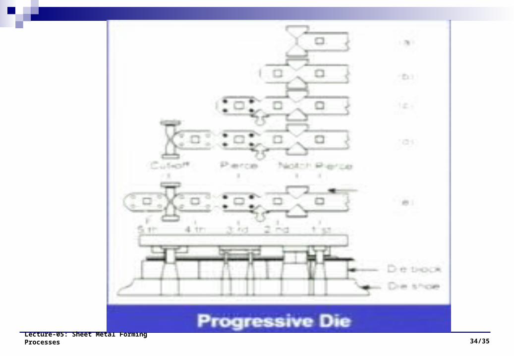
Progressive Dies
Lecture-05: Sheet Metal Forming Processes 34/36
Has series of station.
At each station, w/p is operated
during a press stroke.
Piercing,blanking,Forming, Drawing
etc. are done in each Stations.
Between stroke,metal sheet piece
is transferred to next station.
Die –punch blocks can be easily
replacable.
Highest production rates compared
to other Dies.
Lecture-05: Sheet Metal Forming Processes 34/37
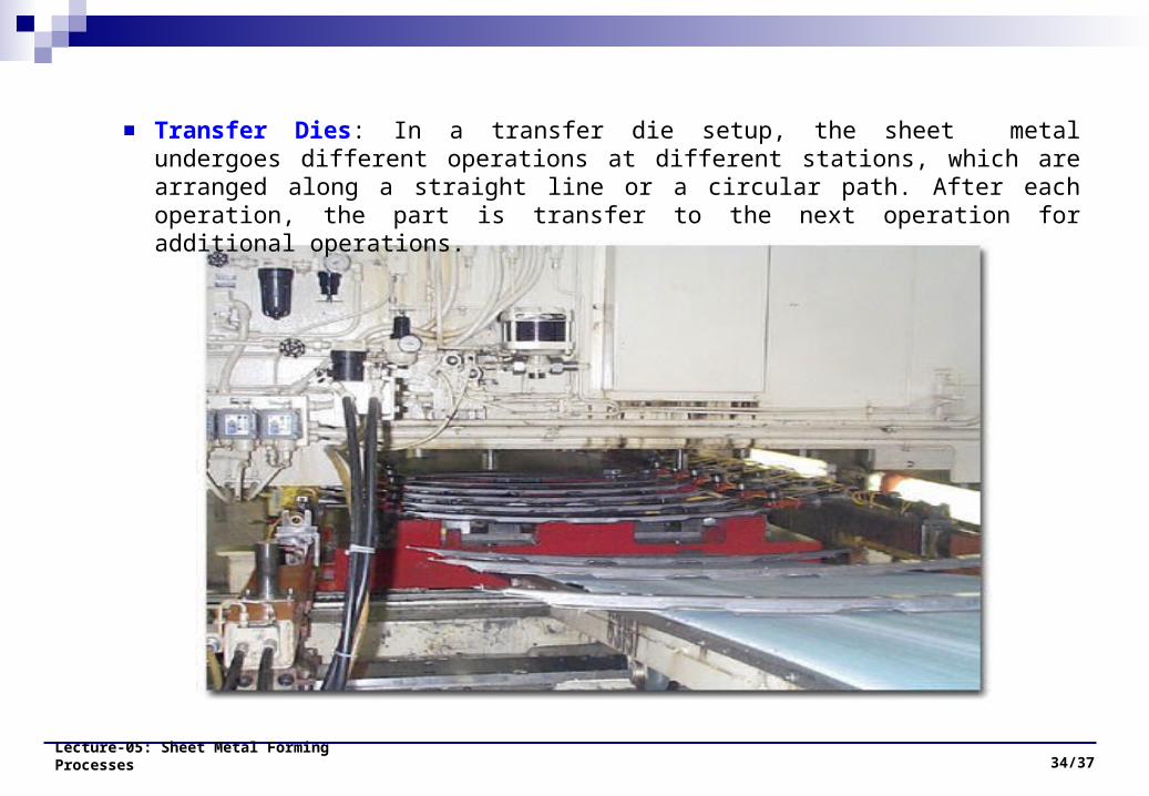
Transfer Dies: In a transfer die setup, the sheet metal undergoes different operations at different stations, which are arranged along a straight line or a circular path. After each operation, the part is transfer to the next operation for additional operations.

Cutting actions in Dies
Lecture-05: Sheet Metal Forming Processes 34/38
Punch is smaller than Die in all
sides by an amount called
clearance.
Punch pushes w/p into Die
cavity, so w/p is subjected to
tensile & compressive forces.
Highest stress will b at die-
punch edges & w/p will start
cracking there.
Steps: Stretching w/p beyond
its elastic limit, Plastic
deformation, reduction in area,
fracturing starts & ends.

Clearance
Lecture-05: Sheet Metal Forming Processes 34/39
Punch is smaller than Die in all sides
by an amount called clearance.
Clearance angle depends on
stock material & w/p thickness.
Mostly Clearance angle is kept
2˚

Lecture-05: Sheet Metal Forming Processes 34/40

Lecture-05: Sheet Metal Forming Processes 34/41

Lecture-05: Sheet Metal Forming Processes 34/42

Lecture-05: Sheet Metal Forming Processes 34/43


