CAT.EUS100-56B-UK Series PSE PSE200 PSE200 Multi-channel Digital Pressure Sensor Controller Multi-channel Digital Pressure Sensor Controller PSE300 PSE300 2-Color Display Digital Pressure Sensor Controller 2-Colour Display Digital Pressure Sensor Controller DIN rail/Terminal block type DIN rail/Terminal block type Current input specification is added. Current input specification is added. New New Connection type Connection type Remote Type Pressure Sensors Pressure Sensor Controllers Compact Pressure Sensor for Pneumatics Compact Pressure Sensor for Pneumatics PSE530 Compact Pressure Sensor for Pneumatics PSE530 Compact Pressure Sensor for Pneumatics PSE540 Compact Pressure Sensor for Pneumatics PSE540 Low Differential Pressure Sensor PSE550 Low Differential Pressure Sensor PSE550 Pressure Sensor for General Fluids PSE560 Pressure Sensor for General Fluids PSE560
Peak/Bottom values holding Displays the maximum and minimum values being set and can keep those values on the display.
Auto-preset Able to set the pressure automatically. In the case of adsorption confirmation, it memorizes the pressurewhen adsorbed and released. By repeating several times, the optimum values are calculated automatically.
Auto-shift Stable switch output is available even though the supply pressure may fluctuate. Automatically corrects the set value in accordance with the fluctuations in the supply pressure.
Display calibrationAble to adjust the displayed value (±5%) and justify distribution of the values displayed on respective pressure switch.
Anti-chattering Prevents malfunction due to sharp pressure fluctuations. The detection of momentary pressure fluctuation as abnormal pressure can be prevented by changing the setting of the response time.
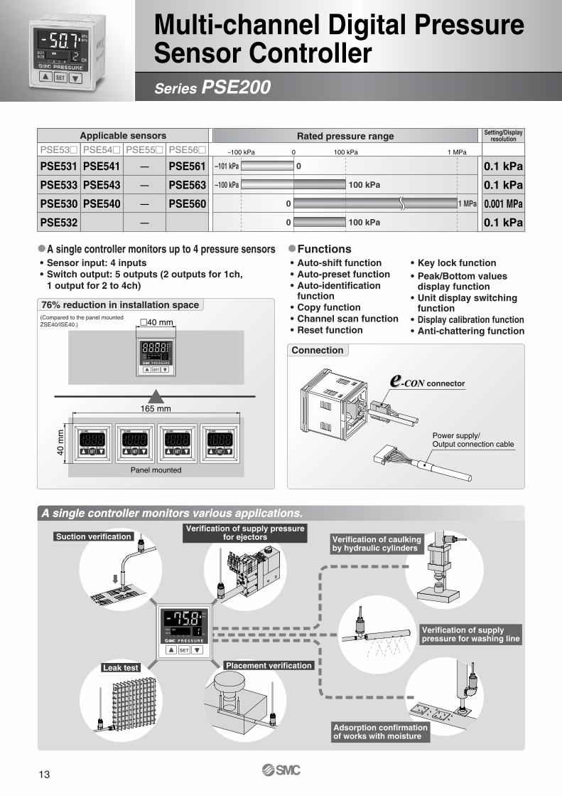
PSE53� PSE54� PSE55� PSE56�
Vacuum
Compoundpressure
Positivepressure
Low differentialpressure
PSE531
PSE533
PSE532
—
PSE530
—
PSE541
PSE543
—
—
PSE540
—
—
—
—
—
—
PSE550
PSE561
PSE563
—
PSE564
PSE560
—
–100 kPa
–101 kPa 0
0
0
0
500 kPa
1 MPa
0 2 kPa
–100 kPa 100 kPa
100 kPa
0 100 kPa 500 kPa 1 MPa
PSE200 PSE300
0.1 kPa
0.1 kPa
0.1 kPa
—
0.001 MPa
—
0.1 kPa
0.2 kPa
0.1 kPa
1 kPa
0.001 MPa
0.01 kPa
Rated pressure range
Applicable pressure sensor model
Series PSE
PSE531
PSE533
PSE532
—
PSE530
—
PSE541
PSE543
—
—
PSE540
—
—
—
—
—
—
PSE550
PSE561
PSE563
—
PSE564
PSE560
—
Pressure Sensors/Series PSE5��
Input/Outputspecifications
Setting/Display resolution
Input/Outputspecifications
• NPN 5 outputs +auto-shift input
• PNP 5 outputs +auto-shift input
• NPN 2 outputs + 1–5 V outputs• NPN 2 outputs + 4–20 mA outputs• NPN 2 outputs +
auto-shift input• PNP 2 outputs + 1–5 V outputs• PNP 2 outputs + 4–20 mA outputs• PNP 5 outputs +
Low pressure sensor (PSE532-�) is used to detect minute differentiations. Auto-shift function reduces influence of fluctuations in the supply pressure.
Inspection of a radiatorSeries PSE532 + PSE300
Connection
Compact Pressure Sensor For Pneumatics
Application examplesApplication examples
1
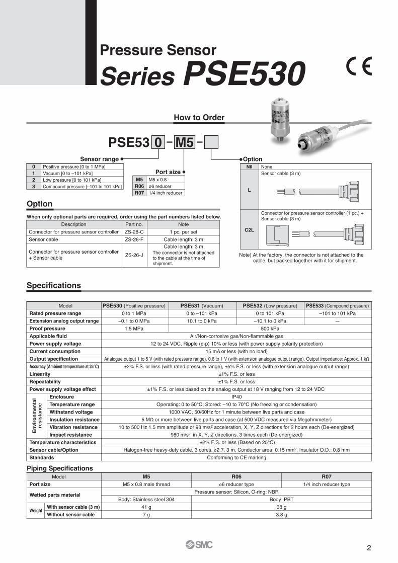
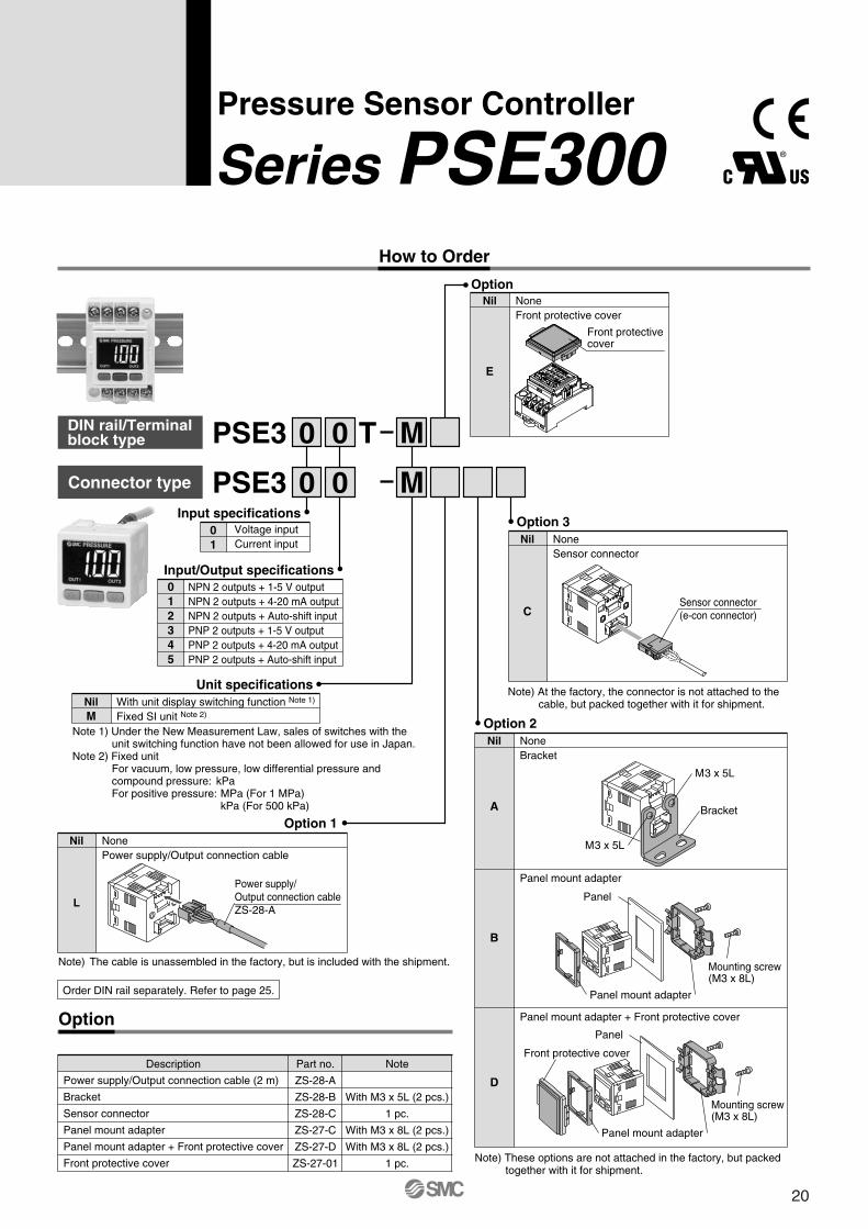
Series PSE530How to Order
Pressure Sensor
Option
When only optional parts are required, order using the part numbers listed below.
PSE53 0 M5
Nil
L
C2L
OptionNone0
123
Sensor rangePositive pressure [0 to 1 MPa]Vacuum [0 to –101 kPa]Low pressure [0 to 101 kPa]Compound pressure [–101 to 101 kPa]
M5R06R07
Port sizeM5 x 0.8ø6 reducer1/4 inch reducer
Sensor cable (3 m)
Connector for pressure sensor controller (1 pc.) + Sensor cable (3 m)
Description Part no.
ZS-28-C
ZS-26-F
ZS-26-J
Note
1 pc. per set
Cable length: 3 m
Connector for pressure sensor controller
Sensor cable
Connector for pressure sensor controller + Sensor cable
Piping SpecificationsModel M5
M5 x 0.8 male thread
R06ø6 reducer type
Pressure sensor: Silicon, O-ring: NBR
Body: PBT
38 g
3.8 g
Body: Stainless steel 304
41 g
7 g
R071/4 inch reducer typePort size
Wetted parts material
With sensor cable (3 m)
Without sensor cableWeight
Specifications
Model PSE530 (Positive pressure)
0 to 1 MPa
–0.1 to 0 MPa
1.5 MPa
PSE531 (Vacuum)
0 to –101 kPa
10.1 to 0 kPa
Air/Non-corrosive gas/Non-flammable gas
12 to 24 VDC, Ripple (p-p) 10% or less (with power supply polarity protection)
15 mA or less (with no load)
Analogue output 1 to 5 V (with rated pressure range), 0.6 to 1 V (with extension analogue output range), Output impedance: Approx. 1 kΩ
±2% F.S. or less (with rated pressure range), ±5% F.S. or less (with extension analogue output range)
±1% F.S. or less
PSE533 (Compound pressure)
–101 to 101 kPa
—
PSE532 (Low pressure)
0 to 101 kPa
–10.1 to 0 kPa
500 kPa
Rated pressure range
Extension analog output range
Proof pressure
Applicable fluid
Power supply voltage
Current consumption
Output specification
Accuracy (Ambient temperature at 25°C)
Linearity
Repeatability
Power supply voltage effect
Enclosure
Temperature range
Withstand voltage
Insulation resistance
Vibration resistance
Impact resistance
Temperature characteristics
Sensor cable/Option
Standards
±1% F.S. or less
±1% F.S. or less based on the analog output at 18 V ranging from 12 to 24 VDC
IP40
Operating: 0 to 50°C; Stored: –10 to 70°C (No freezing or condensation)
1000 VAC, 50/60Hz for 1 minute between live parts and case
5 MΩ or more between live parts and case (at 500 VDC measured via Megohmmeter)
10 to 500 Hz 1.5 mm amplitude or 98 m/s2 acceleration, X, Y, Z directions for 2 hours each (De-energized)
980 m/s2 in X, Y, Z directions, 3 times each (De-energized)
±2% F.S. or less (Based on 25°C)
Halogen-free heavy-duty cable, 3 cores, ø2.7, 3 m, Conductor area: 0.15 mm2, Insulator O.D.: 0.8 mm
Conforming to CE marking
En
viro
nm
enta
lre
sist
ance
Cable length: 3 m
Note) At the factory, the connector is not attached to the cable, but packed together with it for shipment.
The connector is not attachedto the cable at the time ofshipment.
2
Internal Circuit
Dimensions
PSE53�-M5
Analogue Output
With sensor cable
5 5.5
4
3
29.427.2
M5 x 0.8
Pressure port
3.4
5.4
12
ø2.5
ø13
ø12
ø7.
2
ø2.
7ø
10.4
Pressure port
ø7.
2ø
12 øD
45.543.3
PSE53�-
3.4
5.4
9.8
1
Pressure
5
1 to 5 VDC
AC
0.6
B
Range
Forvacuum
For lowpressureFor positive
pressure
For compoundpressure
0 to –101 kPa
Rated pressurerange A
0
B
–101 kPa
C
10.1 kPa
–101 kPa to 101 kPa –101 kPa 101 kPa —
0 to 101 kPa 0 101 kPa –10.1 kPa
0 to 1 MPa 0 1 MPa –0.1 MPa
PSE53�Voltage output type1 to 5 VOutput impedanceApprox. 1 kΩ (Analogue
output)
1 kΩ
Load
12 to 24 VDC
Brown DC (+)
Black OUT
Blue DC (–)
+–
R06R07
Applicable fitting size (D)
6
1/4"
(mm)
Model
PSE53�-R06
PSE53�-R07
Ana
log
outp
ut [V
]
Mai
n ci
rcui
t
Series PSE530
3
Application examplesApplication examples
Series PSE540
PSE540
PSE541
PSE543
Series Rated pressure range
0
100 kPa–100 kPa
–101 kPa
–100 kPa 0 100 kPa 500 kPa 1 MPa
• Weight: 2.9 g
• Head size: 9.6 x 20.8 x 18 mm
In case of PSE54�-M3
189.6
20.8
0 1 MPa
Compact Pressure Sensor For Pneumatics
Pads can be directly mounted. Manifolding is possible.
4
How to Order
Option
Part no.
ZS-28-C
Note
1 pc.
Description
Connector for pressure sensor controller
PSE54 1 M3
Note) At the factory, the connector is not attached to the cable, but packed together with it for shipment.
M5 female thread,through type
M5 female thread,through type(with mounting hole)
Port size
IM5
IM5H
Sensor range
Specifications
Piping Specifications
Model
Model M3
M3 x 0.5
M5
M5 x 0.8
01R1/8
M5 x 0.8
N01NPT1/8
M5 x 0.8
R04
ø4 reducer
R06
ø6 reducer
IM5M5 female
thread,through type
IM5HM5 female
thread,through type
(with mounting hole)
42.4 g
2.9 g
42.7 g
3.2 g
49.3 g
9.8 g
41.4 g
1.9 g
41.6 g
2.1 g
43.3 g
3.8 g
44.1 g
4.6 g
PSE5410 to –101 kPa
10.1 to 0 kPa
PSE5400 to 1 MPa
–0.1 to 0 MPa
1.5 MPa
Rated pressure range
Extension analog output range
Proof pressure
Applicable fluid
Power supply voltage
Current consumption
Output specification
Accuracy (Ambient temperatureat 25°C)
Linearity
Repeatability
Power supply voltage effect
Temperature characteristics
Standards
Port size
Material
Sensor cable
Weight
Enclosure
Operating temperature range
Operating humidity range
Withstand voltage
Insulation resistance
Vibration resistance
Impact resistance
Case
Pressure sensing section
With sensor cable
Without sensor cable
Resin case: PBTFitting: Stainless steel 303
Resin case: PBTFitting: C3604BD PBT
Resin case: PBTFitting: A6063S-T5
Pressure sensor: Silicon, O-ring: NBR
Oil proof heavy-duty vinyl cable (ellipse), 3 cores, 2.7 x 3.2, 3 m, Conductor area: 0.15 mm2, Insulator O.D.: 0.9 mm
M3 x 0.5
M5 x 0.8
R 1/8 (with M5 female thread)
NPT 1/8 (with M5 female thread)
ø4 reducer
ø6 reducer
M3
M5
01
N01
R04
R06
Option (Connector)Nil None
C2
Connector for pressuresensor controller (1 pc.)
®
Air/Non-corrosive gas/Non-flammable gas
12 to 24 VDC, Ripple (p-p) 10% or less (with power supply polarity protection)
15 mA or less
Analogue output 1 to 5 V (with rated pressure range), 0.6 to 1 V (with extension analogue output range), Output impedance: Approx. 1 kΩ
PSE54�: ±2% F.S. or less (with rated pressure range), ±5% F.S. or less (with extension analogue output range)PSE54�A: ±1% F.S. or less (with rated pressure range), ±3% F.S. or less (with extension analogue output range)
±0.2% F.S. or less
±0.8% F.S. or less
IP40
Operating: 0 to 50°C, Stored: –20 to 70°C (No freezing or condensation)
Operating/Stored: 35 to 85% RH (No condensation)
1000 VAC, 50/60 Hz for 1 minute between live parts and case
50 MΩ or more between live parts and case (at 500 VDC measured via Megohmmeter)
10 to 500 Hz at whichever is smaller of 1.5 mm amplitude or 98 m/s2 acceleration, in X, Y, Z directions, for 2 hours each (De-energized)
980 m/s2 in X, Y, Z directions, 3 times each (De-energized)
±2% F.S. or less (Based on 25°C)
Conforming to CE marking, UL (CSA)
±2% F.S.±1% F.S.
AccuracyNilA
500 kPa
±0.4% F.S. or less±0.7% F.S. or less
PSE543–100 to 100 kPa
—
En
viro
nm
enta
lre
sist
ance
Series PSE540Compact Pressure Sensor For Pneumatics
013
Positive pressure [0 to 1 MPa]Negative pressure [0 to –101 kPa]Compound pressure [–100 to 100 kPa]
5
Internal Circuit
Dimensions
PSE54�Voltage output type1 to 5 VOutput impedanceApprox. 1 kΩ
Common Dimensions
A
PSE54�-M5PSE54�-M3
11.510.8
B 3.5 3
PSE54�- 01N01
PSE54�-M3M5
A
PSE54�-R06PSE54�-R04
ø6ø4
B 2018
PSE54�-R04R06
PSE54�-IM5
PSE54�-IM5H
With across flats 7
With across flats 12
(Analog output)
1 kΩ
Load
12 to 24 VDC
Brown DC (+)
Black OUT
Blue DC (–)
Analogue Output
10.6
Pressure
5
1 to 5 VDC
AC B
Range
Forvacuum
For positivepressure
For compoundpressure
Rated pressurerange A B C
B10
A
8.7
9
9.6
18 300013
14.4
10
M5 x 0.8
01: R1/8N01: NPT1/8
7
8.7
13 3 ø3.4
+–
(mm) (mm)
M3: M3 x 0.5M5: M5 x 0.8
10A B
4
M5 x 0.8
8
M5 x 0.8
Mai
n ci
rcui
t
Ana
log
outp
ut [V
] 0 to –101kPa
–100 kPa to 100 kPa
0 to 1 MPa
0
–100 kPa
0
–101 kPa
100 kPa
1 MPa
10.1 kPa
—
–0.1 MPa
Compact Pressure Sensor for Pneumatics Series PSE540
6
Can control air flow by monitoring the flow rate inside the duct.
Can control filtration and replacement periods by monitoring the clogging of the filter.
Can detect the liquid level through changes in the purge pressure.
LED display
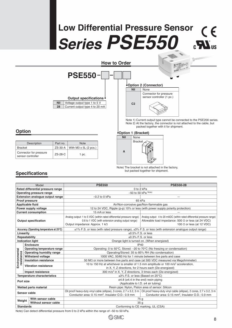
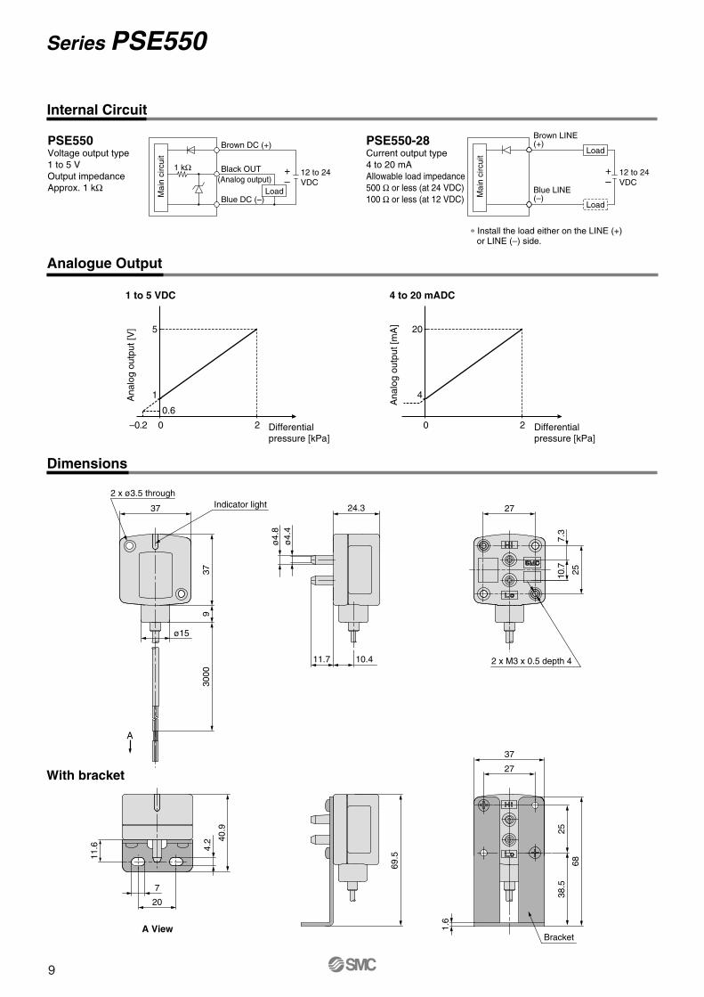
Series PSE550
PSE550
Series Rated pressure range
0 2 kPa
0 1 kPa 2 kPa
Mounting directly Mounting withbracket
With LED display for confirming energization
2 mounting typesAccuracy
±1% F.S.
Proof pressure
65 kPa65 kPa
Low Differential Pressure Sensor
Flow controlSeries PSE550
Liquid level detectionSeries PSE550
Filter clogging monitoringSeries PSE550
±1% F.S.
Application examplesApplication examples
7
How to Order
Option
Description Part no.
ZS-30-A
ZS-28-C
Note
With M3 x 5L (2 pcs.)
1 pc.
Bracket
PSE550
Note) The bracket is not attached in the factory, but packed together for shipment.
Option 2 (Connector)Nil
C2
Connector for pressure sensor controller (1 pc.)
Note 1) Current output type cannot be connected to the PSE200 series.Note 2) At the factory, the connector is not attached to the cable, but
packed together with it for shipment.
Voltage output type 1 to 5 VCurrent output type 4 to 20 mA
Nil28
Output specifications
Option 1 (Bracket)Nil
A
®
Specifications
Model PSE550 PSE550-28
15 mA or less —
–0.2 to 0 kPa —
Oil proof heavy-duty vinyl cable (ellipse), 3 cores, 2.7 x 3.2, 3 mConductor area: 0.15 mm2, Insulator O.D.: 0.9 mm
Oil proof heavy-duty vinyl cable (ellipse), 2 cores, 2.7 x 3.2, 3 mConductor area: 0.15 mm2, Insulator O.D.: 0.9 mm
Accuracy (Operating temperature at 25°C)LinearityRepeatabilityIndication light
EnclosureOperating temperature rangeOperating humidity rangeWithstand voltageInsulation resistance
Vibration resistance
Impact resistance
0 to 2 kPa–50 to 50 kPa Note)
65 kPaAir/Non-corrosive gas/Non-flammable gas
12 to 24 VDC, Ripple (p-p) 10% or less (with power supply polarity protection)
±1% F.S. or less (with rated pressure range), ±3% F.S. or less (with extension analogue output range)±0.5% F.S. or less±0.3% F.S. or less
Orange light is turned on. (When energized)IP40
Operating: 0 to 50°C, Stored: –20 to 70°C (No freezing or condensation)Operating/Stored: 35 to 85% RH (No condensation)
1000 VAC, 50/60 Hz for 1 minute between live parts and case50 MΩ or more between live parts and case (at 500 VDC measured via Megohmmeter)
10 to 150 Hz at whichever is smaller of 1.5 mm amplitude or 100 m/s2 acceleration, in X, Y, Z directions, for 2 hours each (De-energized)
300 m/s2 in X, Y, Z directions, 3 times each (De-energized)±3% F.S. or less (Based on 25°C)ø4.8 (ø4.4 in the end) resin piping(Applicable to I.D. ø4 air tubing)
Resin pipe: Nylon, Piston area of sensor: Silicon
75 g35 g
Conforming to CE marking, UL (CSA)
None
Note) Can detect differential pressure from 0 to 2 kPa within the range of –50 to 50 kPa.
NoneBracket
Connector for pressuresensor controller
Analog output: 4 to 20 mADC (within rated differential pressure range)Allowable load impedance: 500 Ω or less (at 24 VDC) 100 Ω or less (at 12 VDC)
Analog output: 1 to 5 VDC (within rated differential pressure range) 0.6 to 1 VDC (with extension analog output range)Output impedance: Approx. 1 kΩ
En
viro
nm
enta
lre
sist
ance
Series PSE550Low Differential Pressure Sensor
8
Internal Circuit
Analogue Output
Dimensions
PSE550Voltage output type1 to 5 VOutput impedanceApprox. 1 kΩ
PSE550-28Current output type4 to 20 mAAllowable load impedance500 Ω or less (at 24 VDC)100 Ω or less (at 12 VDC)
(Analog output)1 kΩ
Load
12 to 24 VDC
Black OUT
Load
12 to 24 VDC
Brown LINE(+)
Blue LINE(–)
Load
∗ Install the load either on the LINE (+)or LINE (–) side.
Washing line Adsorption confirmation ofwork pieces with moisture
Verification of caulking byhydraulic cylinders
Note: Please be careful of the inertial force of sudden water irruption at the time of vacuum release. Parts such as the adapter with throttle (ZS-31-X175 etc.) are available as a measure to avoid sudden irruption. Please refer to the back of page 3 (About intrusion of water or drainage) for details.
∗ For URJ1/4, TSJ1/4, refer to the back of page 3.
Pressure Sensor For General Fluids
Application examplesApplication examples
10
How to Order
PSE56 0 01Port size
0134
Positive pressure [0 to 1 MPa]Vacuum [0 to –101 kPa]Compound pressure [–100 to 100 kPa]Positive pressure [0 to 500 kPa]
∗ This adapter is used to mount the PSE200 series on the panel fitting of the PSE100 series.
Panel mount adapter
Front protective cover +Panel mount adapter
Series PSE200Multi-channel Controller
14
Specifications
PSE200 PSE201
NPN open collector output: 5 outputs(Sensor input CH1: 2 outputs, CH2 to 4: 1 output)
PNP open collector output: 5 outputs(Sensor input CH1: 2 outputs, CH2 to 4: 1 output)
12 to 24 VDC, Ripple (p-p) 10% or less (with power supply polarity protection)
55 mA or less (Current consumption for sensor is not included.)
[Power supply voltage] –1.5 V
40 mA maximum (100 mA maximum for the total power supply current when 4 sensors are input.)
1 to 5 VDC (Input impedance: Approx. 800 kΩ)
4 inputs
With excess voltage protection (Up to 26.4 V)
80 mA
1 V or less (with load current of 80 mA)
5 ms or less (Response time selections with anti-chattering function: 20 ms, 160 ms, 640 ms)
With short circuit protection function
±0.1% F.S. ±1 digit or less
Adjustable (can be set from 0)
Fixed (3 digits)
For measured value display: 4-digit, 7-segment indicator, Display color: Orange (Sampling frequency: 4 times/sec)
For channel display: 1-digit, 7-segment indicator, Display color: Red
±0.5% F.S. ±1 digit or less
Red (Lights up when output is turned ON.)
Non-voltage input (Reed or Solid state), Input 10 ms or more, Independently controllable auto-shift function ON/OFF
With auto-identification function Note 2)
Front face: IP65 (when panel-mounted), Others: IP40
Operating: 0 to 50°C, Stored: –10 to 60°C (No freezing or condensation)
Operating/Stored: 35 to 85% RH (No condensation)
10 to 500 Hz at whichever is smaller of 1.5 mm amplitude or 98 m/s2 acceleration, in X, Y, Z directions for 2 hrs. each (De-energized)
980 m/s2 in X, Y, Z directions, 3 times each (De-energized)
±0.5% F.S. or less (Based on 25°C)
Power supply/Output connection: 8P connector, Sensor connection: e-con connector
Housing: PBT; Display: Transparent nylon; Back rubber cover: CR
Approx. 60 g (Excluding power supply/output cable)
Oil proof heavy-duty vinyl cable, 8 cores, ø4.8, 2 m, Conductor area: 0.15 mm2, Insulator O.D.: 0.9 mm
Conforming to CE marking
For compound pressure
PSE533PSE543PSE563
–101 to 101 kPa
0.1 kPa
For vacuum
PSE531PSE541PSE561
10 to –101 kPa
0.1 kPa
For low pressure
PSE532
–10 to 101 kPa
0.1 kPa
For positive pressure
PSE530PSE560
–0.1 to 1 MPa
0.001 MPa
Note 1) If the Vcc and 0 V side of the sensor input connector are short circuited, the inside of the controller will be damaged.Note 2) Auto-identification function comes with “the PSE53� series” pressure sensor only. Other SMC series (PSE540 and 560) are not equipped with this function.
Power supply voltage
Current consumption
Power supply voltage for sensor
Power supply current for sensor Note 1)
Sensor input
Switch output
Repeatability
Hysteresis
Display
Display accuracy (Operating temerature at 25°C)
Indication light
Auto-shift input
Auto-identification function
Environmentalresistance
Temperature characteristics
Connection
Material
Weight
Power supply/Output connection cable
Standards
Number of inputs
Input protection
Maximum load current
Maximum load voltage
Residual voltage
Response time
Short circuit protection
Hysteresis mode
Window comparator mode
Enclosure
Ambient temperature range
Ambient humidity range
Vibration resistance
Impact resistance
Model
Pressure range
Applicable pressure sensor
Set pressure range
Setting/Display resolution
30 V —
Series PSE200
15
Pin no.
Power supply/Output connection cable (Accessory)
2000
PIN no.
q
w
e
r
t
y
u
i
Terminal
DC (+)
DC (–)
CH1_OUT1
CH1_OUT2
CH2_OUT1
CH3_OUT1
CH4_OUT1
Auto-shift input
iuytrewq
Dimensions
PSE200/201
Power supply/Output connector (8P)
Sensor connector (4P x 4) Connector (Option)
Terminal
DC (+)
N.C
DC (–)
IN (1 to 5 V)
MADE IN JAPAN
PSE200
ZZ
6
40.1
2.5
(7.5)
�36
.8
Sensor connector(Option)
r
e
w
q
�40
CH
kPaMPa
SET
4321OUT2OUT1
PRESSURE
PIN no.
q
w
e
r
8 Yellow : Auto-shift input
7 Green : CH4_OUT1
6 Red : CH3_OUT1
5 Gray : CH2_OUT1
4 White : CH1_OUT2
3 Black : CH1_OUT1
2 Blue : DC (–)
1 Brown: DC (+)
Multi-channel Controller Series PSE200
16
Dimensions
Front protective cover + Panel mount
�48 conversion adapter + Panel mount
Panel fitting dimensionApplicable panel thickness: 0.5 to 8 mm
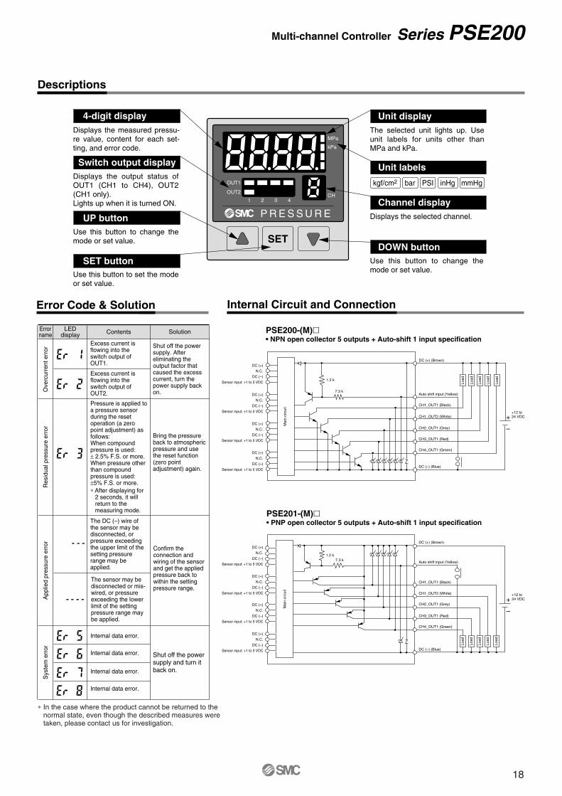
Displays the output status of OUT1 (CH1 to CH4), OUT2 (CH1 only).Lights up when it is turned ON.
Use this button to change the mode or set value.
Use this button to set the mode or set value.
Displays the measured pressu-re value, content for each set-ting, and error code.
Use this button to change the mode or set value.
Displays the selected channel.
The selected unit lights up. Use unit labels for units other than MPa and kPa.
∗ In the case where the product cannot be returned to the normal state, even though the described measures were taken, please contact us for investigation.
Error Code & Solution
LEDdisplay
Errorname Contents
Ove
rcur
rent
err
orR
esid
ual p
ress
ure
erro
rA
pplie
d pr
essu
re e
rror
Sys
tem
err
or
Solution
Excess current is flowing into the switch output of OUT1.
Excess current is flowing into the switch output of OUT2.
The DC (–) wire of the sensor may be disconnected, or pressure exceeding the upper limit of the setting pressure range may be applied.
The sensor may be disconnected or mis-wired, or pressure exceeding the lower limit of the setting pressure range may be applied.
Pressure is applied to a pressure sensor during the reset operation (a zero point adjustment) as follows: When compound pressure is used: ± 2.5% F.S. or more.When pressure other than compound pressure is used: ±5% F.S. or more.∗ After displaying for
2 seconds, it will return to the measuring mode.
Shut off the power supply. After eliminating the output factor that caused the excess current, turn the power supply back on.
Bring the pressure back to atmospheric pressure and use the reset function (zero point adjustment) again.
Confirm the connection and wiring of the sensor and get the applied pressure back to within the setting pressure range.
Shut off the power supply and turn it back on.
Internal data error.
Internal data error.
Internal data error.
Internal data error.
Internal Circuit and Connection
Load
Load
Load
Load
Load
Mai
n ci
rcui
t
Load
Load
Mai
n ci
rcui
t
Load
Load
Load
Multi-channel Controller Series PSE200
18
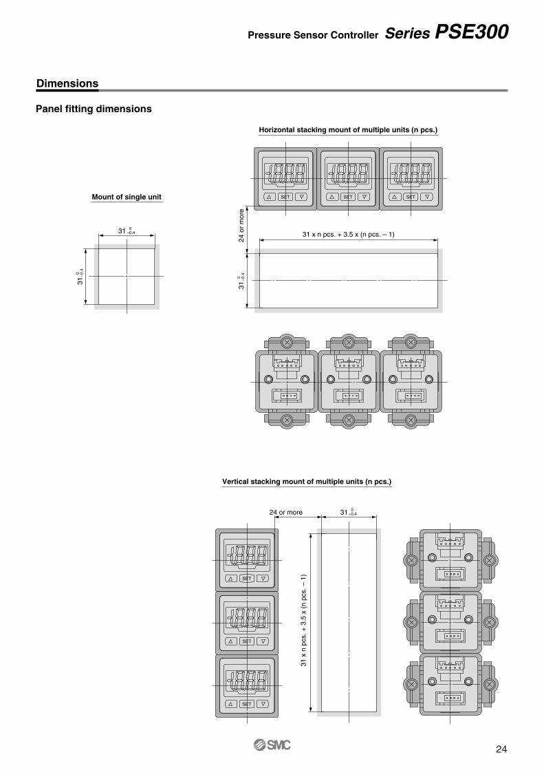
Can be mounted in close proximitywith each other either horizontallyor vertically.
Series PSE300
Response time
�Functions • Auto-shift function • Auto-preset function • Display calibration function • Peak/Bottom values display function • Key lock function • Reset function • Error indication function • Unit display switching function • Anti-chattering function
PSE531
PSE533
PSE530
PSE532
—
—
PSE53� PSE54� PSE55� PSE56�
PSE541
PSE543
PSE540
—
—
—
—
—
—
—
—
PSE550
0.1 kPa
0.2 kPa
0.001 MPa
0.1 kPa
1 kPa
0.01 kPa
Applicable sensors
–101 kPa
0 100 kPa
0 2 kPa
0
–100 kPa 100 kPa
–100 kPa 0 100 kPa 500 kPa 1 MPa
0 1 MPa
0 500 kPa
Power supply/Output connector
Sensor connector
Reduced panel fitting labor
SET
MPaPRESSURE
SET
MPaPRESSURE
SET
MPaPRESSURE
OUT1 OUT2OUT1 OUT2OUT1 OUT2
�30 mm
Connection
1 ms1 ms
connector
Rated pressure range Setting/Displayresolution
DIN rail/Terminal block type NewNew Current input NewNew
PSE31�(Current input type)
Electrical current input (4 to 20 mADC) isadded to the sensor input.
Note) The cable is unassembled in the factory, but is included with the shipment.
20
Specifications
Analogue Output
Model PSE3��
12 to 24 VDC ±10%, Ripple (p-p) 10% or less (with power supply polarity protection)50 mA or less (Current consumption for sensor is not included.)
PSE30�: Voltage input 1 to 5 VDC (Input impedance: 1 MΩ)PSE31�: Current input 4 to 20 mADC (Input impedance: 100 Ω)
1 inputWith excess voltage protection (Up to 26.4 V)
Hysterisis mode: Variable, Window comparator mode: VariableNPN or PNP open collector output: 2 outputs
80 mA30 VDC (at NPN output)
1 V or less (with load current of 80 mA)With short circuit protection
1 ms or lessResponse time settings for anti-chattering function: 20 ms, 160 ms, 640 ms, 1280 ms
±0.1% F.S. or lessOutput voltage: 1 to 5 V (within rated pressure range (Differential pressure)), 0.6 to 1 V (within extension analogue output range)Output impedance: Approx. 1 kΩ, Linearity: ±0.2% F.S. (Not including sensor accuracy), Response speed: 150 ms or less
Set (differential) pressure rangeSetting/Display resolutionPressure range Note 1)
Rated (differential) pressure rangeExtension analog output rangePower supply voltageCurrent consumption
Sensor input
HysteresisSwitch output
Response time
Repeatability
DisplayIndicator lightAuto-shift input Note 2)
Temperature characteristics
Connection
Material
Weight
Power supply/Output connection cableStandards
EnclosureOperating temperature rangeOperating humidity rangeWithstand voltageInsulation resistanceVibration resistanceImpact resistance
Maximum load currentMaximum load voltageResidual voltageOutput protection
Voltage output Note 2)
Accuracy (To display value) (25°C)
Current output Note 2)
Accuracy (To display value) (25°C)
Anti-chattering function
Number of inputsInput protection
–101 to 101 kPa0.2 kPa
For compound pressure–100 to 100 kPa
—
PSE533PSE543PSE563
PSE531PSE541PSE561
PSE532 PSE530PSE560 PSE564 PSE550
10 to –101 kPa0.1 kPa
For vacuum0 to –101 kPa10.1 to 0 kPa
–10 to 100 kPa0.1 kPa
For low pressure0 to 100 kPa–10 to 0 kPa
–0.1 to 1 MPa0.001 MPa
0 to 1 MPa–0.1 to 0 MPa
For positive pressure
–50 to 500 kPa1 kPa
0 to 500 kPa–50 to 0 kPa
–0.2 to 2 kPa0.01 kPa
For low differential pressure0 to 2 kPa
–0.2 to 0 kPa
Note 1) Pressure range can be selected during initial setting.Note 2) Auto-shift function is not available when analogue output option is selected. Also, analogue output option is not available when auto-shift function is selected.
±0.6% F.S. or less
±1.0% F.S. or less ±1.5% F.S. or less ±2.0% F.S. or less
±1.0% F.S. or less ±1.5% F.S. or less
±0.5% F.S.±2 digits or less
±0.5% F.S. ±1 digit or less
With power supply/Output connection cable
Without power supply/Output connection cable
10.6
PressureDifferentialpressure
5
1 to 5VDC
AC
EF
BD
42.4
PressureDifferentialpressure
20
4 to 20 mADC
AC
EF
BD
RangeFor vacuum
For compound pressureFor low pressure
For positivepressure
Rated pressure range0 to –101 kPa
–100 kPa to 100 kPa0 to 100 kPa0 to 1 MPa
0 to 500 kPa
A0
–100 kPa000
B–101 kPa100 kPa100 kPa1 MPa
500 kPa
RangeFor low differential pressure
Rated pressure range0 to 2 kPa
C0
D2 kPa
E10.1 kPa
—–10 kPa
–0.1 MPa–50 kPa
F–0.2 kPa
Series PSE300
Note 3) The following units can be selected with unit conversion function: For vacuum & compound pressure: kPa·kgf/cm2·bar·psi·mmHg·inHg For positive pressure & low pressure: MPa·kPa·kgf/cm2·bar·psi For low differential pressure: kPa·mmH2O
Output current: 4 to 20 mA (within rated pressure range (Differential pressure)), 2.4 to 4 mA (within extension analogue output range)Maximum load impedance: 300 Ω (at 12 VDC), 600 Ω (at 24 VDC), Minimum load impedance: 50 Ω
Linearity: ±0.2% F.S. (Not including sensor accuracy), Response time: 150 ms or less
3 + 1/2 digit, 7 segment indicator, 2-colour display (Red/Green), Sampling frequency: 5 times/secOUT1: Lights up when turned ON (Green), OUT2: Lights up when turned ON (Red)
Non-voltage input (Reed or Solid state), Low level input: 5 ms or more, Low level: 0.4 V or lessIP40
Operating: 0 to 50°C, Stored: –10 to 60°C (No freezing or condensation)Operating/Stored: 35 to 85% RH (No condensation)1000 VAC for 1 minute between live parts and case
50 MΩ or more between live parts and case (at 500 VDC Megohmmeter)10 to 150 Hz at whichever is smaller of 1.5 mm amplitude or 98 m/s2 acceleration, in X, Y, Z directions, for 2 hours each (De-energized)
100 m/s2 in X, Y, Z directions, 3 times each (De-energized)±0.5% F.S. or less (Based on 25°C)
Front case: PBT, Rear case: PBT (PSE3��), Denaturated PPE (PSE3��T)PSE3��: 85 g
Displays the current pressure, set mode, selected display unit, and error code. Four different display settings are available. Always use red or green display; or switch between green and red according to the output.
Lights up when OUT2 is turned ON.
Use this button to change the mode or confirm the set value.
Use this button to select the mode or decrease the ON/OFF set value.It is also used for switching to the bottom display mode.
Use this button to select the mode or increase the ON/OFF set value.It is also used for switching to the peak display mode.
Lights up when OUT1 is turned ON.
LCD
Output (OUT1) display (Green)
Up button
Output (OUT2) display (Red)
SET button
Down button
PSE3�0NPN open collector output (2 outputs), Max. 30 V or 80 mA, residual voltage 1 V or lessAnalogue output: 1 to 5 VOutput impedance: Approx. 1 kΩ
PSE3�3PNP open collector output (2 outputs), Max. 80 mA, residual voltage 1 V or lessAnalogue output: 1 to 5 VOutput impedance: Approx. 1 kΩ
PSE3�1NPN open collector output (2 outputs), Max. 30 V or 80 mA, residual voltage 1 V or lessAnalogue output: 4 to 20 mAMaximum load impedance: 300 Ω (12 VDC), 600 Ω (24 VDC)Minimum load impedance: 50 Ω
PSE3�4PNP open collector output (2 outputs), Max. 80 mA, residual voltage 1 V or lessAnalogue output: 4 to 20 mAMaximum load impedance: 300 Ω (12 VDC), 600 Ω (24 VDC)Minimum load impedance: 50 Ω
PSE3�2NPN open collector output with auto-shift input (2 outputs),Max. 30 V, 80 mA, residual voltage 1 V or less
Note: The colours in parentheses indicate the color of the lead wire when it is connected to the power supply / output connection cable (ZS-28-A).
PSE3�5PNP open collector output with auto-shift input (2 outputs),Max. 80 mA, residual voltage 1 V or less
Pressure Sensor Controller Series PSE300
DC (+)
Mai
n ci
rcui
t
12 to 24 VDC
+
–
(Brown)Analog output
(Grey)
(Black)
(White)
(Blue)
OUT1
OUT2
DC (–)Load
DC (+)
Mai
n ci
rcui
t
(Brown)Analog output
(Grey)
(Black)
(White)
(Blue)
OUT1
OUT2
DC (–)Load
12 to 24 VDC
+
–
Load
Load
Load
Load
DC (+)
12 to 24 VDC
+
–
(Brown)
Load
Analog output
(Grey)
(Black)
(White)
(Blue)
OUT1
OUT2
DC (–)
Load
DC (+)
(Brown)Analogue output
(Grey)
(Black)
(White)
(Blue)
OUT1
OUT2
DC (–)Load
12 to 24 VDC
+
–
Mai
n ci
rcui
t
Mai
n ci
rcui
tLoad
Load
Load
12 to 24 VDC
+
–
Auto-shift input
DC (+)
12 to 24 VDC
+
–
Load
(Brown)
(Grey)
(Black)
(White)
(Blue)
OUT1
OUT2
DC (–)
Auto-shift input
DC (+)
(Brown)
(Grey)
(Black)
(White)
(Blue)
OUT1
OUT2
DC (–)
Mai
n ci
rcui
t Load
Load
Mai
n ci
rcui
t
Load
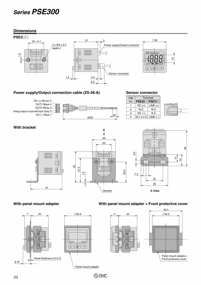
22
Dimensions
1.5
depth 42 x M3 x 0.5
20 ± 0.1 �30
10
8.2
3.21.5
331
Power supply/Output connector
Sensor connector
DC (+) Brown 5OUT1 Black 4OUT2 White 3
Analog output or auto-shift input Gray 2DC (–) Blue 1 20
2020
PINno.
1234
PSE31�LINE (+)
N.C.N.C.
LINE (–)
PSE30�DC (+)N.C.
DC (–)IN (1 to 5 V)
A View
4.2
10
15
46
22
35
7.2
With bracket
With panel mount adapter With panel mount adapter + Front protective cover
Power supply/Output connection cable (ZS-28-A) Sensor connector
2411
42.4
Panel mount adapter + Front protective cover
�34.5247
8.75Panel thickness 0.5 to 6
4 3
2 1
Series PSE300
PSE3��
Panel mount adapter
�34.5
1.6
40
Bracket
26.5
30
20
31.5
A
Terminal
41
23
Panel fitting dimensions
31 x
n p
cs. +
3.5
x (
n pc
s. –
1)
3124 or more
3131 x n pcs. + 3.5 x (n pcs. – 1)
24
or m
ore
Mount of single unit
0 –0.4
Horizontal stacking mount of multiple units (n pcs.)
Vertical stacking mount of multiple units (n pcs.)
0–0.4
31
310 –0
.4
0–0.4
Pressure Sensor Controller Series PSE300
Dimensions
24
Connections
Series PSE300
DIN Rail
5.5
8 4.51.25
L
7.5
35 35
ISA-5-�
PSE3��T
Part no. LISA-5-1ISA-5-2ISA-5-3ISA-5-4ISA-5-5ISA-5-6ISA-5-7
When there are large fluctuations in the supply pressure, the switch may fail to operate correctly. The auto-shift function compensates such supply pressure fluctuations. It measures the (differential) pressure at the time of auto-shift signal input and uses it as the reference (differential) pressure to correct the set value on the switch.
∗ Rectified valueWhen the auto-shift is selected, “ooo” will be displayed for approximately 1 second, and the pressure value at that point will be saved as a rectified value “C_5” (for CH1 of PSE200 and PSE300) or “C_3” (for CH2 to 4 for PSE200). Based on the saved rectified values (Note), the set value “P_1” to “P_4” (for PSE200) or “P_1”, “H_1”, “P_3”, “H_2” (for PSE300) will likewise be rectified.
Note) When an output is reversed, “n_1” to “n_4” (for PSE200) or “n_1”, “H_1”, “n_3”, “H_2” (for PSE300) will be rectified.
Auto-shift zero (Series PSE300 only) The basic function of auto-shift zero is the same as the function for auto-shift. Also it corrects values on the display, based on a pressure value of 0, when the auto-shift is selected.
Formula for Obtaining the Set Value
D Peak and bottom display functionThis function constantly detects and updates the maximum and minimum values and allows to hold the display value.For PSE300, when the �� are simultaneously pressed for 1 second or longer, while “holding”, the hold value will be reset.
E Key lock function
F Reset function
This function clears and resets the zero value on the display of measured (differential) pressure within ±7% F.S. of the factory adjusted value.
B Auto-preset functionAuto-preset function, when selected in the initial setting, calculates and stores the set value from the measured (differential) pressure.The optimum set value is determined automatically by repeating vacuum and break with the target workpiece several times.
This function eliminates slight differences in the output values and allows uniformity in the numbers displayed. Displayed values of the pressure sensors can be adjusted to within ±5%.
PSE200 Regulating pressure(Differential pressure) range Possible set range
PSE300 Regulating pressure(Differential pressure) range Possible set range
Compound pressure
Vacuum
Low pressure
Positive pressure
Low differential pressure
–101.0 to 101.0 kPa
10.0 to –101.0 kPa
–10.0 to 101.0 kPa
–0.1 to 1.000 MPa
—
—
–101.0 to 101.0 kPa
101.0 to –101.0 kPa
–100.0 to 101.0 kPa
–1.000 to 1.000 MPa
—
—
Compound pressure
Vacuum
Low pressure
Positive pressure
Low differential pressure
–101.0 to 101.0 kPa
10.0 to –101.0 kPa
–10 to 100.0 kPa
–0.1 to 1.000 MPa
–50 to 500 kPa
–0.2 to 2.00 kPa
–101.0 to 101.0 kPa
101.0 to –101.0 kPa
–100.0 to 100.0 kPa
–1.000 to 1.000 MPa
–500 to 500 kPa
–2.00 to 2.00 kPa
PSE200PSE300
P_1(P_3)=A-(A-B)/4
P_1 or P_3 P_2(H_1) or P_4(H_2)
P_2(P_4)=B+(A-B)/4
H_1(H_2)=(A-B)/2
Possible Set Range for Auto-Shift Input
Adsorption Verification
Max. A
P-1
P-2
Min. B
Set value correction by auto-shift function
H-1
PSE200PSE300
10 ms or more
5 ms or more
A Auto-shift inputtime
15 ms or less
10 ms or less
B Switch output response timeat time of auto-shift input
Pressure Sensor Controller Series PSE200/300
This function prevents incorrect operations such as accidentally changing the set value.
Supply pressurenormal
(Diff
eren
tial)
Pre
ssur
e
Rec
tifie
dva
lue∗Rectified value∗
Switchoutput1·(2)
Auto-shiftinput
Supply pressuredrop
Supply pressureincrease
Switch output response time when auto- shift is input.
Work 1 Work 2
Work 1 Work 2 Work n
Work n
HighVacuum
Atmosphere
Adsorption
Non-adsorption
Dis
play
pre
ssur
e va
lue
Note) When the precision indicator setting function is used, the set (differential) pressure value may change ±1 digit.
26
Series PSE200/300
Function Details
J Anti-chattering functionA large bore cylinder or ejector consumes a large volume of air in operation and may experience a temporary drop in the supply pressure. This function prevents detection of such temporary drops in the supply pressure as an error.
Pressure ↑Momentary change
t (ms) t (ms) Time →
Time →
Time →
<Averaging> <Averaging>
Switch outputoperation in
normalconditions
ON
OFF
Switch outputoperation whenanti-chatteringfunction is on
ON
OFF
Pressure rangeP-1
H-1
G
K Anti-chattering function (Series PSE200 only)Pressure value for the selected channel is displayed.
L Anti-chattering function (Series PSE200 only)Pressure values for each channel are displayed by turns at 2-second intervals.
PSE200PSE300
20 ms, 160 ms, 640 ms
Available response time settings
20 ms, 160 ms, 640 ms, 1280 ms
<Principle>This function averages pressure values measured during the response time set by the user and then compares the average pressure value with the pressure set point value to output the result on the switch.
Error code
PSE200 PSE300Errorname Description
Load current of switch output (OUT1) exceeds 80 mA.
Load current of switch output (OUT2) exceeds 80 mA.
Pressure applied during the zero reset operation exceeds ±7% F.S.∗ After displaying the error code for 3
seconds, the switch automatically returns to the measuring mode. Due to individual product differences, the setting range varies ±4 digits.
Supply pressure exceeds the maximum set (differential) pressure or upper limit of the display pressure.
A sensor may be disconnected or mis-wired. Or, supply pressure is below the minimum set (differential) pressure or lower limit of the display pressure.
The value measured at the time of auto-shift input is outside the set (differential) pressure range.∗ After displaying the error code for one
second, the switch returns to the measuring mode.
Internal data error
Internal data error
Internal data error
Internal data error
Ove
rcur
rent
er
ror
Res
idua
lpr
essu
re e
rror
App
lied
pres
sure
er
ror
Aut
o-sh
ifter
ror
Sys
tem
err
or
Error indication function
H Copy function (Series PSE200 only)Information that can be copied includes the following: q Pressure set values, w Range settings, e Display units, r Output modes, t Response times.• When CH1 is copied to CH2, CH3, and CH4, information of OUT1
in CH1 will be copied.• When CH2, CH3, or CH4 is copied to CH1, information of OUT1 in
CH2, CH3, or CH4 will be copied only to OUT1 in CH1.
Note) When the copy function is used, the regulating pressure value of the copied channel may change ±1 digit.
I Auto-identification function (Series PSE200 only)This function automatically identifies the pressure range of the pres-sure sensor that is connected to the multi-channel pressure sensor controller, thus eliminating the need of having to reset the range again after replacing the sensor. This function will be activated either when “Aon” is set in the auto-identification mode or when the power is turned back on in that condition. However, this function only works in conjunction with specific pressure sensors (SMC Series PSE53�). When other pressure sensors are used, this function will not work. When using other types of pressure sensors, first set the auto-identification mode to “AoF”, and then proceed to setting the range. Turning the power back on while in the “Aon” setting can cause a malfunction.
27
Pressure Sensor Controller Series PSE200/300
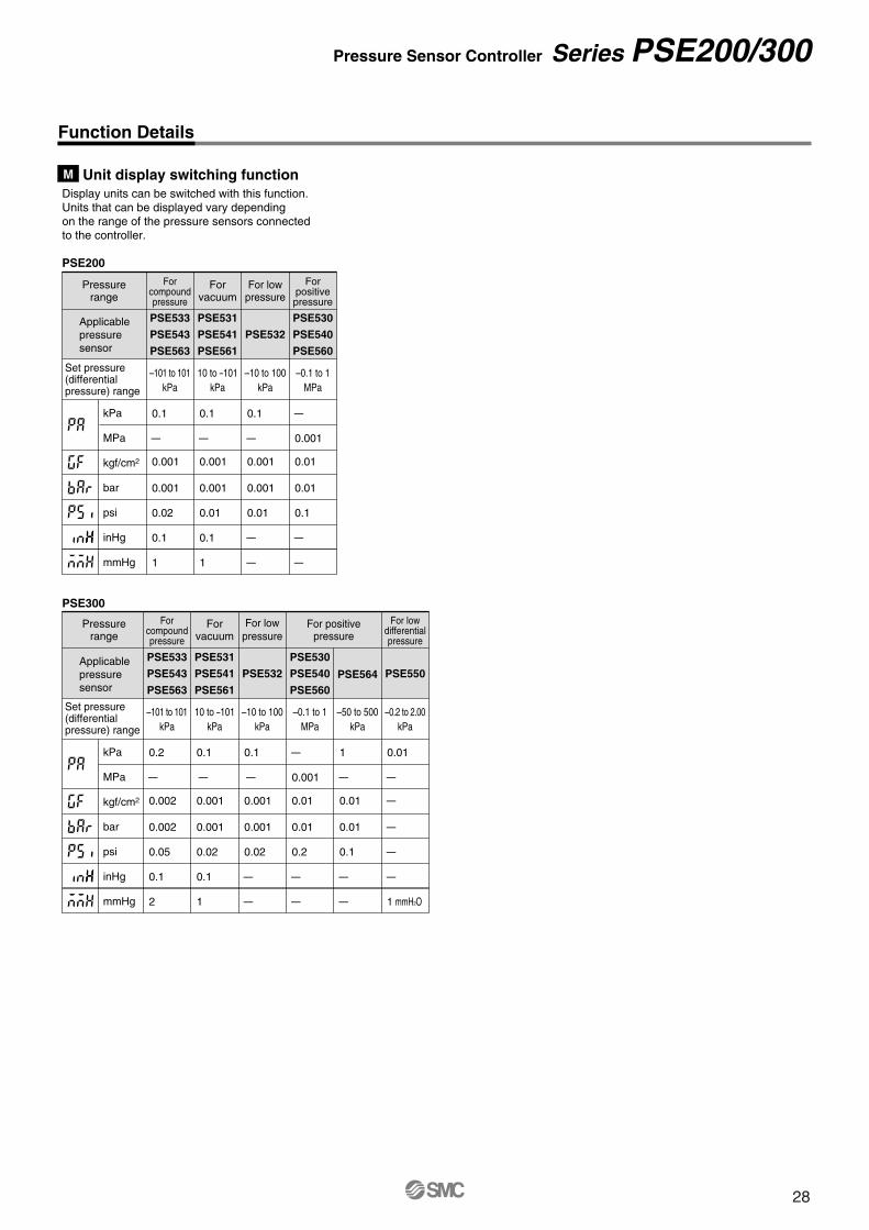
M Unit display switching functionDisplay units can be switched with this function.Units that can be displayed vary dependingon the range of the pressure sensors connectedto the controller.
PSE200
PSE300
Pressurerange
Applicablepressuresensor
Applicablepressuresensor
0.1
—
0.001
0.001
0.02
0.1
1
0.1
—
0.001
0.001
0.01
0.1
1
0.1
—
0.001
0.001
0.01
—
—
—
0.001
0.01
0.01
0.1
—
—
Forcompoundpressure
Forvacuum
Forpositivepressure
For lowpressure
PSE533
PSE543
PSE563
PSE531
PSE541
PSE561
PSE530
PSE540
PSE560
PSE532
Set pressure(differentialpressure) range
kPa
MPa
kgf/cm2
bar
psi
inHg
mmHg
–101 to 101kPa
10 to –101kPa
–10 to 100kPa
–0.1 to 1MPa
Pressurerange
0.2
—
0.002
0.002
0.05
0.1
2
0.1
—
0.001
0.001
0.02
0.1
1
0.1
—
0.001
0.001
0.02
—
—
—
0.001
0.01
0.01
0.2
—
—
1
—
0.01
0.01
0.1
—
—
0.01
—
—
—
—
—
1 mmH2O
Forcompoundpressure
Forvacuum
For lowpressure
For positivepressure
PSE530
PSE540
PSE560PSE564
For lowdifferentialpressure
PSE533
PSE543
PSE563
PSE531
PSE541
PSE561
PSE532 PSE550
Set pressure(differentialpressure) range
kPa
MPa
kgf/cm2
bar
psi
inHg
mmHg
–101 to 101kPa
10 to –101kPa
–10 to 100kPa
–0.1 to 1MPa
–50 to 500kPa
–0.2 to 2.00kPa
Function Details
28
• For details about the e-con connector, contact the respective connector manufacturer.
1. Connection of sensor connector• Cut the sensor cable as illustrated
to the right.• Referring to the table below, insert
each lead wire of the cable at the position marked with a number corresponding to the color of the lead wire.
• Confirm that the numbers on the connector match the colours of the wires and that the wires are inserted to the bottom. Press Part A by hand
for temporary fixing.• Press in the central part of Part A vertically with a tool such as pliers.• A sensor connector cannot be taken
apart for reuse once it is crimped. If the wire arrangement is incorrect or if the
wire insertion fails, use a new sensor connector.
• For connection to SMC pressure switches, use sensor connectors
(ZS-28-C�) or e-con connectors listed below.
Series PSE5��Specific Product Precautions 1Be sure to read before handling.Refer to “Precautions for Handling Pneumatic Devices” (M-03-E3A) for Safety Instructions and Pressure Switches Precautions.
1. Do not drop, bump, or apply excessive impact (PSE530, 540: 980 m/s2, PSE560: 500 m/s2, PSE550: 300 m/s2) while handling. Although the body of the sensor may not be damaged, the inside of the sensor could be damaged and lead to malfunction.
2. The tensile strength of the cord is PSE530: 23 N, PSE540, 550, 560: 50 N or less. Applying a greater pulling force to it can cause malfunction. When handling, hold the body of the sensor do not dangle it from the cord.
3. Do not use pressure sensors with corrosive and/or flammable gases or liquids.
(PSE530)1. Do not exceed the screw-in torque of 3.5 N.m when
installing piping. Exceeding this value may cause malfunctioning of the sensor.
2. Connecting the sensor cable (optional)Hold the female connector of the sensor cable with your fingers and carefully insert it into the connector.
WarningHandling
� Pressure Sensors
A connector cover is provided as part of the cable assembly (see the figure below). It is designed to keep the female cover in place, first make sure it is facing in the right direction as you slip it over the female connector, then lock it to the sensor body by turning it clockwise. To remove the cover, first unlock it by turning it counterclockwise, then pull back on it. To remove the female connector, grab it with your fingers and pull back on it. Do not pull on the cable.
(PSE540/550)1. Care should be taken when stripping the outer cable covering as the insulator may be accidentally
torn or damaged if incorrectly stripped, as shown on the right.
CautionWiring
Back page 1
Pressure Source
1. Use of toxic, corrosive or flammable gasDo not use toxic, corrosive and flammable gas.Also, note that the switch is not explosion-proof.
2. Applicable fluid(PSE530/540/550)Do not use for corrosive, flammable gases or fluids.
(PSE560)The fluid contact areas are stainless steel 316L (pressure sensor fittings). Use fluid that will not corrode the materials.(For corrosiveness of fluid, consult the manufacturer of the fluid.)
3. Helium leakage test(PSE56�- only)Helium leakage test is conducted on the welding parts. Use a ferrule by Swagelok Company (Swagelok® fittings) as the TSJ fittings and packing, ground, etc. by Swagelok Company (VCR® fittings) as the URJ fittings. If a ferrule, packing or ground by other manufacturers are to be used, conduct helium leakage test before using those products.∗ Swagelok® and VCR® are trademarks of Swagelok Company.
4. About intrusion of water or drainage(PSE560)Although the pressure sensor of this switch employs a stainless steel diaphragm, there are cases in which the inertial force of sudden irruption at the time of vacuum release after adsorption confirmation causes water, or drainage contained in the air, to strike the pressure sensor and damage it.In such cases, an intermediate orifice can be set up, or an adapter with external throttle (ZS-31-X175, X186, X188, X189) can be mounted to the fitting part of the main body.
Warning
(PSE550)• Cut the tubing vertically.• Carefully hold the tubing and
slowly push it into the resin pipe, ensuring that it is inserted by more than 8 mm. For your information, the tensile strength is approx. 25 N when inserted by more than 8 mm.
• Insert the low pressure tubing into “Lo” pipe, and the high-pressure tubing into “Hi” pipe.
• In cases where SMC tubing is not used, make sure the product has similar I.D. accuracy within ø4±0.3 mm.
• Make sure that the tubing is firmly inserted to avoid possible disconnection. (Tensile strength is approx. 25 N when being inserted 8 mm.)
Piping Connection
CautionTubing
Resin pipe
A2B2
Series PSE5��Specific Product Precautions 2Be sure to read before handling.Refer to “Precautions for Handling Pneumatic Devices” (M-03-E3A) for Safety Instructions and Pressure Switches Precautions.
Back page 2
Tighten screws 1/4 to 1/2 turn after the heads are flush with the panel.
2 x M3 x 8L
Front protective cover(ZS-26-01) Panel mount
(ZS-26-B)
When using �48 conversion adapter
�48 conversion adapter(ZS-26-D)
Mounting
Standard
Caution
The front face of the panel mount conforms to IP65 (IP40 when using the �48 conversion adapter); however, there is a possibility of liquid filtration if the panel mount adapter is not installed securely and properly. Securely fix the adaptor with screws as shown below.
(PSE200)
� Controllers
1. Do not drop, bump, or apply excessive impact (PSE200: 980 m/s2, PSE300: 100 m/s2) while handling. Although the body of the controller case may not be damaged, the inside of the controller could be damaged and cause malfunction.
2. The tensile strength of the power supply/output connection cable is 50 N; that of the pressure sensor lead wire with connector is 25 N. Applying a greater pulling force than the applicable specified tensile strength to either of these components can lead to malfunction. When handling, hold the body of the controller.
WarningHandling
(PSE300T)
1. Please affix the main body by hooking the claws of the lower part over the DIN rail and pressing in the direction of the arrows as shown in Figure (a).When removing the main body, use a flat head screwdriver or similar tool to pull it in the direction of the arrows as shown in Figure (b).
M3 x 5L
Bracket(Part no. ZS-28-B)
M3 x 5L
Panel
Panel mount adapter (Part no. ZS-27-C)Rotate 90° to mount.
Front protective cover(Part no. ZS-27-01) M3 x 8L
Claw
Claw
Figure (b)Figure (a)
Series PSE200/300Specific Product Precautions 1Be sure to read before handling.Refer to “Precautions for Handling Pneumatic Devices” (M-03-E3A) for Safety Instructions and Pressure Switches Precautions.
Handling
Caution(PSE300)1. Mounting with bracket
Mount the bracket on the body with two M3 x 5L mounting screws.Tighten the bracket mounting screws at a tightening torque of 0.5 to 0.7 N·m.
2. Mounting with panel mount adapterSecure the panel mount adapter with two M3 x 8L mounting screws.
3. Panel mount adapter removalTo remove the controller with panel mount adapter from the equipment, remove the two mounting screws, and pull out the controller while pushing the claws outward.Failure to follow this procedure can cause damage to the controller and panel mount adapter.
An M3 terminal screw is used.If employing a crimping terminal, please use the part shown below.
Please tighten the terminal screw with a tightening torque of 0.3 to 0.35 N·m.
Lever
Lever
Sensor connector
Sensor connector
6.2or less
3.2 or more
6.2or less
ø3.2 or more
(Unit: mm)
1. Incorrect wiring can damage the switch and cause malfunction or erroneous switch output. Connections should be done while the power is turned off.
2. Do not attempt to insert or pull out the pressure sensor or its connector when the power is on. Switch output may malfunction.
3. Wire separately from power lines and high voltage lines, avoiding wiring in the same conduit with these lines. Malfunctions may occur due to noise from these other lines.
4. If a commercial switching regulator is used, make sure that the F.G. terminal is grounded.
Connection
Warning
Wiring
Caution
2. Connection of power supply cable and output cable• Securely connect the power supply cable and the output ca-
ble to the body until a click is heard.
(PSE200)
(PSE300)
1. Connection and removal of sensor connector• Hold the lever and connector body with two fingers and insert the connector straight into the pin until it is locked with
a click sound.• To remove the connector, pull it out straight while pressing
the lever with one finger.
1. Our pressure sensor controllers are CE marked; however, they are not equipped with surge protection against lightning. Lightning surge countermeasures should be applied directly to system components as necessary.
(PSE200)• If the product is mounted on a panel, the “IP65”
enclosure rating is applicable only to the front parts. Never use pressure sensor in the presence of flammable or explosive gases.
Operating Environment
Warning
Series PSE200/300Specific Product Precautions 2Be sure to read before handling.Refer to “Precautions for Handling Pneumatic Devices” (M-03-E3A) for Safety Instructions and Pressure Switches Precautions.
Back page 4
Safety Instructions Be sure to read “Handling Precautions for SMC Products” (M-E03-3) before using.
Specifications are subject to change without prior notice and any obligation on the part of the manufacturer.SMC CORPORATION Akihabara UDX 15F, 4-14-1, Sotokanda, Chiyoda-ku, Tokyo 101-0021, JAPAN Phone: 03-5207-8249 FAX: 03-5298-5362
1. The compatibility of the product is the responsibility of the person who designs the equipment or decides its specifications.Since the product specified here is used under various operating conditions, its compatibility with specific equipment must be decided by the person who designs the equipment or decides its specifications based on necessary analysis and test results. The expected performance and safety assurance of the equipment will be the responsibility of the person who has determined its compatibility with the product. This person should also continuously review all specifications of the product referring to its latest catalogue information, with a view to giving due consideration to any possibility of equipment failure when configuring the equipment.
2. Only personnel with appropriate training should operate machinery and equipment.The product specified here may become unsafe if handled incorrectly. The assembly, operation and maintenance of machines or equipment including our products must be performed by an operator who is appropriately trained and experienced.
3. Do not service or attempt to remove product and machinery/equipment until safety is confirmed.1. The inspection and maintenance of machinery/equipment should only be
performed after measures to prevent falling or runaway of the driven objects have been confirmed.
2. When the product is to be removed, confirm that the safety measures as mentioned above are implemented and the power from any appropriate source is cut, and read and understand the specific product precautions of all relevant products carefully.
3. Before machinery/equipment is restarted, take measures to prevent unexpected operation and malfunction.
4. Contact SMC beforehand and take special consideration of safety measures if the product is to be used in any of the following conditions. 1. Conditions and environments outside of the given specifications, or use
outdoors or in a place exposed to direct sunlight.2. Installation on equipment in conjunction with atomic energy, railways, air
navigation, space, shipping, vehicles, military, medical treatment, combustion and recreation, or equipment in contact with food and beverages, emergency stop circuits, clutch and brake circuits in press applications, safety equipment or other applications unsuitable for the standard specifications described in the product catalogue.
3. An application which could have negative effects on people, property, or animals requiring special safety analysis.
4. Use in an interlock circuit, which requires the provision of double interlock for possible failure by using a mechanical protective function, and periodical checks to confirm proper operation.
Warning
Limited warranty and Disclaimer/Compliance Requirements The product used is subject to the following “Limited warranty and Disclaimer” and “Compliance Requirements”.Read and accept them before using the product.
1. The product is provided for use in manufacturing industries.The product herein described is basically provided for peaceful use in manufacturing industries. If considering using the product in other industries, consult SMC beforehand and exchange specifications or a contract if necessary. If anything is unclear, contact your nearest sales branch.
Caution
Limited warranty and Disclaimer1. The warranty period of the product is 1 year in service or 1.5 years after
the product is delivered.∗2)
Also, the product may have specified durability, running distance or replacement parts. Please consult your nearest sales branch.
2. For any failure or damage reported within the warranty period which is clearly our responsibility, a replacement product or necessary parts will be provided. This limited warranty applies only to our product independently, and not to any ot-her damage incurred due to the failure of the product.
3. Prior to using SMC products, please read and understand the warranty terms and disclaimers noted in the specified catalogue for the particular products.
∗2) Vacuum pads are excluded from this 1 year warranty.A vacuum pad is a consumable part, so it is warranted for a year after it is delivered. Also, even within the warranty period, the wear of a product due to the use of the vacuum pad or failure due to the deterioration of rubber material are not covered by the limited warranty.
Compliance Requirements1. The use of SMC products with production equipment for the manufacture of
weapons of mass destruction (WMD) or any other weapon is strictly prohibited.
2. The exports of SMC products or technology from one country to another are governed by the relevant security laws and regulations of the countries involved in the transaction. Prior to the shipment of a SMC product to another country, assure that all local rules governing that export are known and followed.
These safety instructions are intended to prevent hazardous situations and/or equipment damage. These instructions indicate the level of potential hazard with the labels of “Caution,” “Warning” or “Danger.” They are all important notes for safety and must be followed in addition to International Standards (ISO/IEC)∗1), and other safety regulations.
∗1) ISO 4414: Pneumatic fluid power – General rules relating to systems.ISO 4413: Hydraulic fluid power – General rules relating to systems.IEC 60204-1: Safety of machinery – Electrical equipment of machines.
(Part 1: General requirements)ISO 10218-1: Manipulating industrial robots - Safety.etc.
Caution indicates a hazard with a low level of risk which, if not avoided, could result in minor or moderate injury.
Warning indicates a hazard with a medium level of risk which, if not avoided, could result in death or serious injury.
Caution:
Warning:
Danger :Danger indicates a hazard with a high level of risk which, if not avoided, will result in death or serious injury.