prestige Solo 80 250 110 299 155 399 175 Water Boiler Warranty Registration Card must be filled out by the customer and mailed within thirty (30) days of installa- tion in order to gain warranty coverage. When receiving the PRESTIGE Solo unit, any claims for damage or shortage in shipment must be filed immediately against the transportation company by the consignee. Leave all documentation received with appliance with owner for future reference. 2015-9 Prestige ACVMax Install Manual If the information in this manual is not followed exactly, a fire or explosion may result causing property damage, personal injury or death. FOR YOUR SAFETY • Do not store or use gasoline or other flammable vapors and liquids in the vicinity of this or any other appliance. • WHAT TO DO IF YOU SMELL GAS - Do not try to light any appliance - Do not touch any electrical switch; do not use any phone in your building. - Immediately call your gas supplier from a neighbor’s phone. Follow the gas supplier’s instructions. - If you cannot reach your gas supplier, call the fire department. Installation and service must be performed by a qualified installer, service agency or the gas supplier. L I S T E D WARNING NOTICE Revised Date: 12/15/15 * I N S T A L L A T I O N A N D M A I N T E N A N C E * * I N S T A L L A T I O N A N D M A I N T E N A N C E * M A N U A L M A N U A L
Transcript
prestigeSolo 80 250110 299155 399175Water Boiler
Warranty Registration Card must be filled out by the customer and mailed within thirty (30) days of installa-tion in order to gain warranty coverage.When receiving the PRESTIGE Solo unit, any claims for damage or shortage in shipment must be filedimmediately against the transportation company by the consignee.Leave all documentation received with appliance with owner for future reference.
2015-9 Prestige ACVMax Install Manual
If the information in this manual is not followed exactly, a fire or explosion mayresult causing property damage, personal injury or death.
FOR YOUR SAFETY• Do not store or use gasoline or other flammable vapors and liquids in the vicinity of
this or any other appliance.• WHAT TO DO IF YOU SMELL GAS
- Do not try to light any appliance- Do not touch any electrical switch; do not use any phone in your building.- Immediately call your gas supplier from a neighbor’s phone. Follow the gassupplier’s instructions.
- If you cannot reach your gas supplier, call the fire department.Installation and service must be performed by a qualified installer, service agency or thegas supplier.
L I S T E D
WARNING
NOTICE
Revised Date: 12/15/15
* I N S T A L L A T I O N A N D M A I N T E N A N C E * * I N S T A L L A T I O N A N D M A I N T E N A N C E * M A N U A LM A N U A L
SECTION II - Combustion Air and Venting2.1 Combustion Air Contamination ............................................................................52.2 Ventilation and Combustion Air Requirements - Direct Vent ..............................62.3 Ventilation and Combustion Air Requirements - Category IV.............................62.4 Methods of Accessing Combustion Air Into A Space - Category IV...................7
2.4.1 Indoor Combustion Air Opening Size and Location...................................72.4.2 Outdoor Combustion Air Opening Size and Location................................7
2.4.2.1 One Permanent Opening Method ...................................................72.4.2.2 Two Permanent Openings Method ................................................8
2.4.3 Combination of Indoor and Outdoor Combustion Air ..............................92.5 Combustion Air and Vent Piping ..........................................................................92.6 Removal of an Existing Boiler from a Common Vent System ............................102.7 Commonwealth of Massachusetts Installations Only...........................................11
SECTION III - Unit Preparations3.1 Handling Instructions............................................................................................123.2 Wall Mounting Installation ...................................................................................123.3 Wall Mounting Guidelines ....................................................................................123.4 Stud Walls - Installation .......................................................................................13
3.4.1 PRESTIGE Solo 80/110/155/175/250.........................................................133.4.2 PRESTIGE Solo 299/399 ...........................................................................13
SECTION IV - Boiler Piping4.1 General Piping Requirements ...............................................................................144.2 Pressure Relief Valve ............................................................................................144.3 Boiler Air Vent ......................................................................................................144.4 Low Water Cutoff Device .....................................................................................154.5 Additional Limit Control ......................................................................................15
ii
Table of Contents
4.6 Backflow Preventer...............................................................................................164.7 Boiler System Piping Applications .......................................................................164.8 Expansion Tank and Makeup Water .....................................................................16
4.8.1 Diaphragm Expansion Tank ........................................................................164.8.2 Closed-Type Expansion Tank......................................................................16
4.9 Circulator .........................................................................................................194.10 Sizing Primary Piping ...........................................................................................194.11 Domestic Hot Water System Piping .....................................................................194.12 System Piping - Zone Circulators.........................................................................194.13 System Piping - Zone Valves ................................................................................194.14 System Piping - Through Boiler ...........................................................................194.15 System Piping - Radiant Heating..........................................................................194.16 System Piping - Special Application ....................................................................204.17 System Piping - Multiple Units Installation .........................................................20
SECTION V - Installing Vent / Combustion Air & Condensate Drain5.1 Installing Vent and Combustion Air .....................................................................245.2 Installing Condensate Drain Assembly.................................................................24
SECTION VI - Gas Piping6.1 Gas Supply Piping Connection .............................................................................266.2 Natural Gas .........................................................................................................27
6.3 Propane Gas 286.3.1 Pipe Sizing - Propane Gas...........................................................................286.3.2 Propane Gas Supply Pressure Requirements ..............................................28
SECTION VII - Internal Wiring7.1 General Requirements...........................................................................................307.2 Fuse Locations ......................................................................................................30
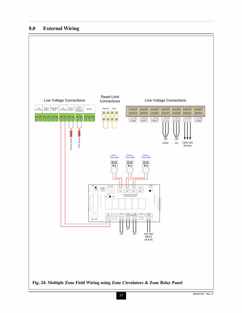
SECTION VIII - External Wiring8.1 Installation Compliance ........................................................................................328.2 Line Voltage Connections .....................................................................................328.3 Circulator Wiring ..................................................................................................328.4 Alarm Wiring ........................................................................................................338.5 Low Voltage Connections .....................................................................................338.6 Thermostat Wiring ................................................................................................338.7 Outdoor Sensor Wiring .........................................................................................348.8 Domestic Hot Water Wiring..................................................................................348.9 Additional Boiler Limits .......................................................................................348.10 External Modulation Control ................................................................................34
iii
Table of Contents
8.11 System Sensor Wiring...........................................................................................348.12 Cascade Wiring .....................................................................................................358.13 Modbus Wiring .....................................................................................................35
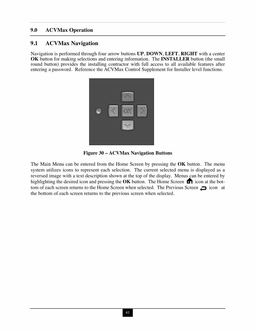
SECTION IX - ACVMax Operation9.1 ACVMax Navigation ............................................................................................419.2 ACVMax Menu Structure.....................................................................................429.3 Home Screen .........................................................................................................439.4 Status Line Messages............................................................................................449.5 Main Menu .........................................................................................................459.6 EZ Setup .........................................................................................................469.7 Heating EZ Setup .................................................................................................46
9.8 Domestic Hot Water EZ Setup .............................................................................489.8.1 Select DHW Demand ..................................................................................489.8.2 Boiler DHW Setpoint ..................................................................................489.8.3 DHW Storage Setpoint ................................................................................489.8.4 DHW Priority Timeout................................................................................49
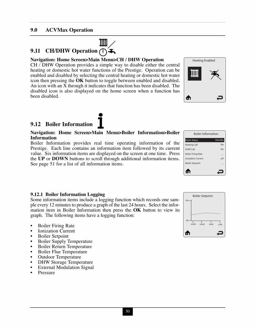
9.9 EZ Setup Reset......................................................................................................499.10 Display EZ Setup ..................................................................................................499.11 CH/DHW Operation .............................................................................................509.12 Boiler Information ...............................................................................................50
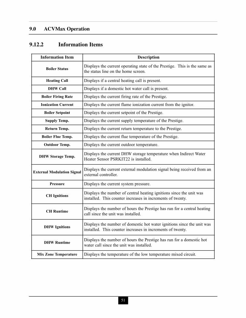
9.12.1 Boiler Information Logging ........................................................................509.12.2 Information Items ........................................................................................51
9.13 Lockout History ...................................................................................................529.13.1 Lockout Details ...........................................................................................529.13.2 Lockout Screen............................................................................................53
SECTION X - Start-Up Preparation10.1 Boiler System Fluid Requirements .......................................................................56
10.1.1 Boiler Fluid pH Level 6.0 to 8.0 .................................................................5610.1.2 Boiler Fluid Hardness Less Than 7 Grains .................................................5610.1.3 Chlorinated Water........................................................................................5610.1.4 Flush Boiler to Remove Sediment ..............................................................5610.1.5 Cleaning of Old Boiler/System: .................................................................5610.1.6 Cleaning of New Boiler/System: ..............................................................5610.1.7 Check and Test Antifreeze...........................................................................57
iv
Table of Contents
10.1.8 Use of Antifreeze in the Boiler System.......................................................5710.2 Filling the Boiler System ......................................................................................5710.3 Check Low Water Cut-Off Device .......................................................................5810.4 Check For Gas Leaks............................................................................................5810.5 Check Thermostat Circuit .....................................................................................5810.6 Inspection of Condensate Drain Assembly...........................................................58
SECTION XI - Start-Up Procedures11.1 Final Checks Before Start-Up...............................................................................5911.2 PRESTIGE Solo Start-Up.....................................................................................5911.3 Check the PRESTIGE Solo and System...............................................................59
SECTION XII - Outdoor Reset Control12.1 Mounting the Outdoor Sensor...............................................................................6412.2 Wiring the Sensor..................................................................................................64
SECTION XIII - External Modulating Control13.1 Wiring the Modulating Controller ........................................................................6513.2 ACVMax Adjustment ...........................................................................................6513.3 Programming of External Modulating Control.....................................................65
SECTION XV - Installation Record
SECTION XVI - Maintenance Schedule16.1 Service Technician ................................................................................................6916.2 Owner Maintenance ..............................................................................................69
SECTION XVII- Maintenance Procedures17.1 Maintenance Procedures .......................................................................................7017.2 Reported Problems................................................................................................7017.3 Check Surrounding Area .....................................................................................7017.4 Inspect Burner Area ..............................................................................................7017.5 Check System Piping ............................................................................................7017.6 Clean Condensate Drain Assembly.......................................................................7117.7 Check Ventilation Air Openings ...........................................................................7117.8 Inspect Vent and Combustion Air Piping..............................................................7117.9 Check Boiler System.............................................................................................7117.10 Check Expansion Tank..........................................................................................7217.11 Check Boiler Relief Valve ....................................................................................7217.12 Inspection of Ignitor..............................................................................................7217.13 Check Ignition Wiring and Ground Wiring ..........................................................7217.14 Check Control Wiring ...........................................................................................73
v
Table of Contents
17.15 Check Control Settings .........................................................................................7317.16 Perform Start-up and Checkout Procedures .........................................................7317.17 Check Burner Flame .............................................................................................7317.18 Check Flame Signal ..............................................................................................7417.19 Check Combustion Levels ....................................................................................7417.20 Check Flue Gas Temperature................................................................................7417.21 Clean Heat Exchanger...........................................................................................7417.22 Review With Owner..............................................................................................7517.23 Handling Previously Fired Combustion Chamber Insulation...............................7517.24 Torque Specifications Table..................................................................................75
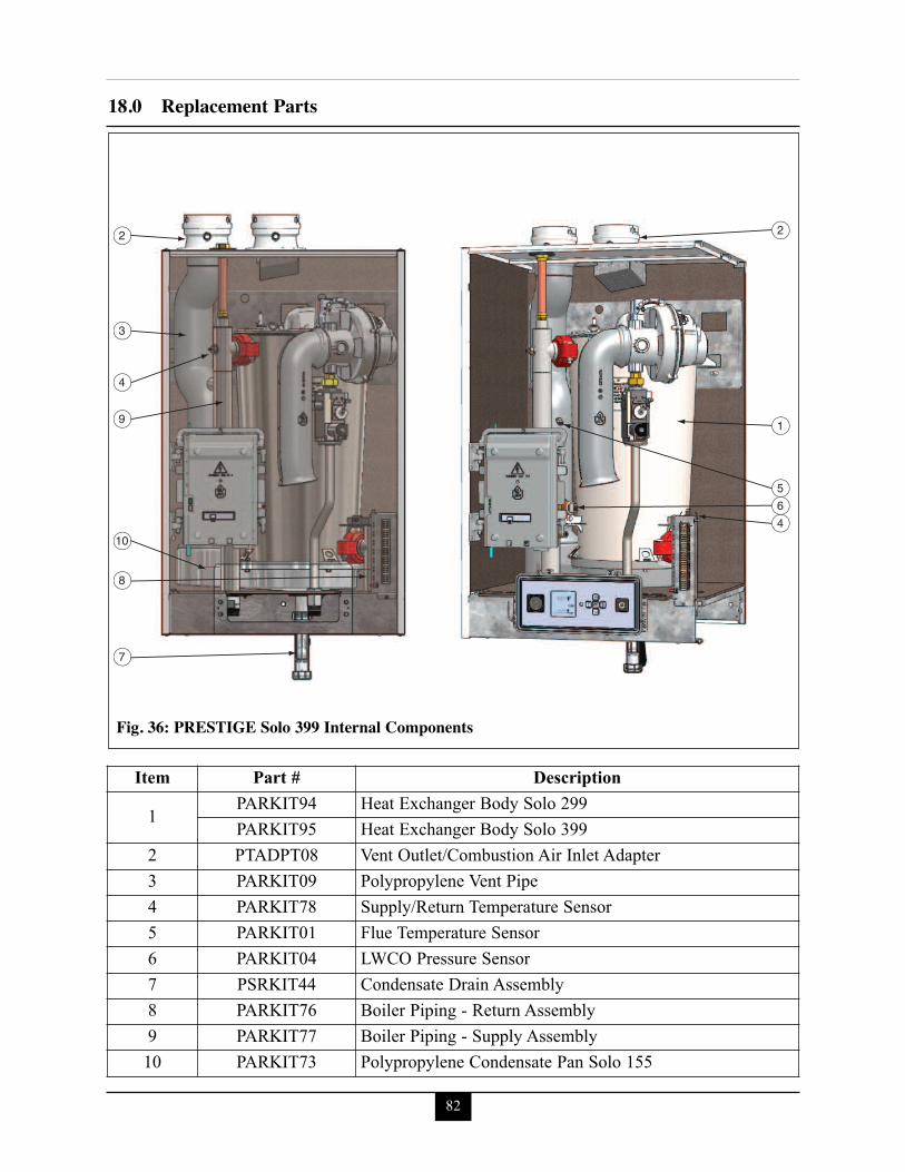
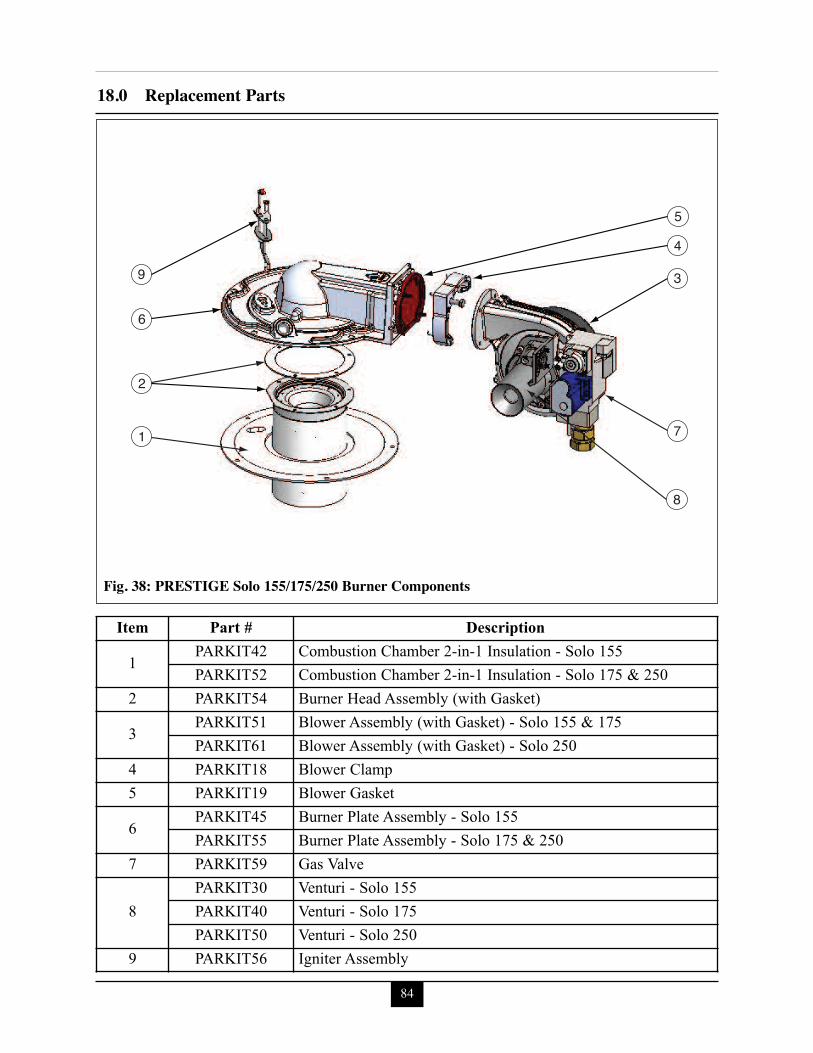
Section XVIII Replacement PartsPRESTIGE Solo 80/110 Jacket Components ..................................................................77PRESTIGE Solo 175/250 Jacket Components................................................................78PRESTIGE Solo 299/399 Jacket Components................................................................79PRESTIGE Solo 80/110 Internal Components ...............................................................80PRESTIGE Solo 155/175/250 Internal Components ......................................................81PRESTIGE Solo 399 Internal Components ....................................................................82PRESTIGE Solo 80/110 Burner Components.................................................................83PRESTIGE Solo 155/175/250 Burner Components........................................................84PRESTIGE Solo 299/399 Burner Components...............................................................85PRESTIGE Solo Display Enclosure................................................................................86PRESTIGE Solo Control Enclosure ................................................................................86
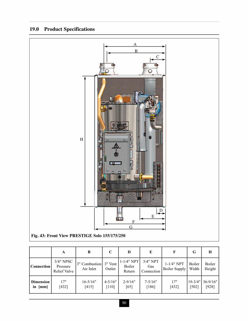
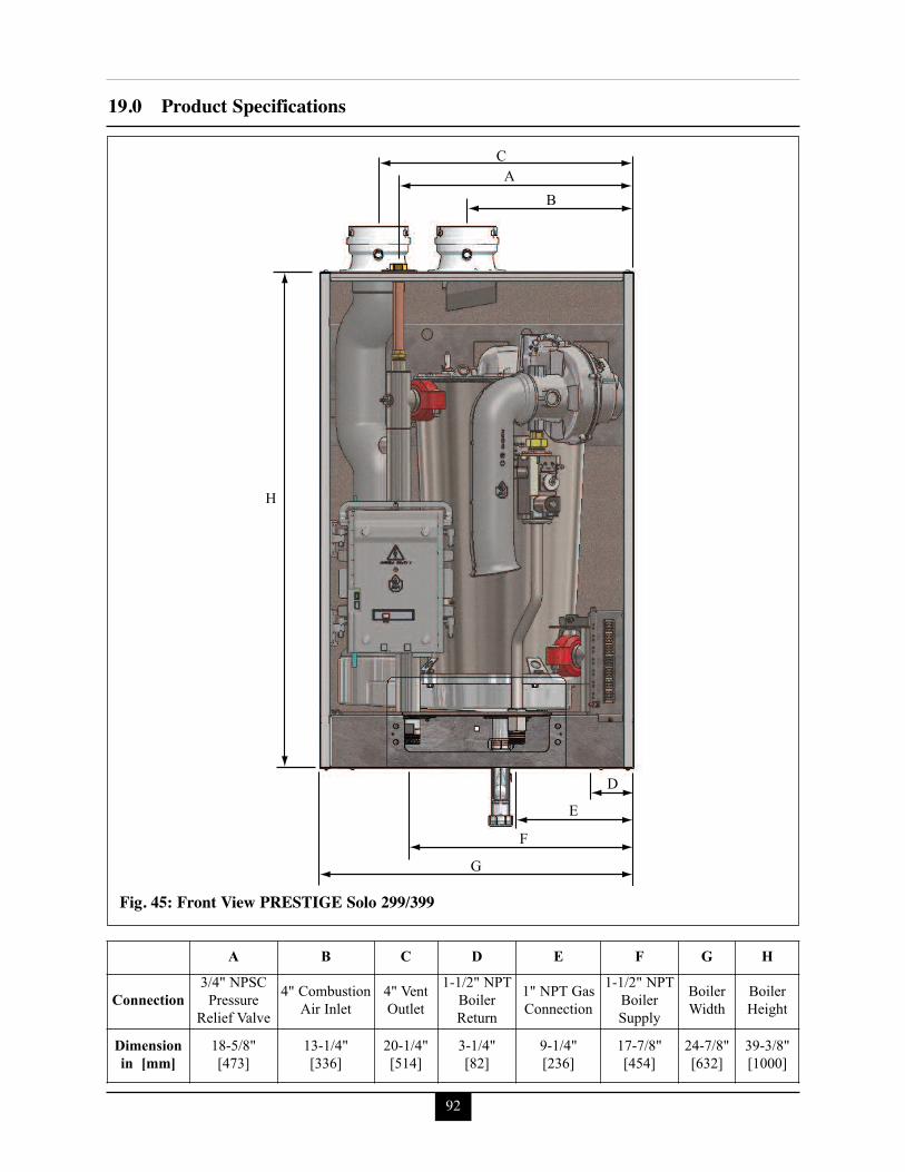
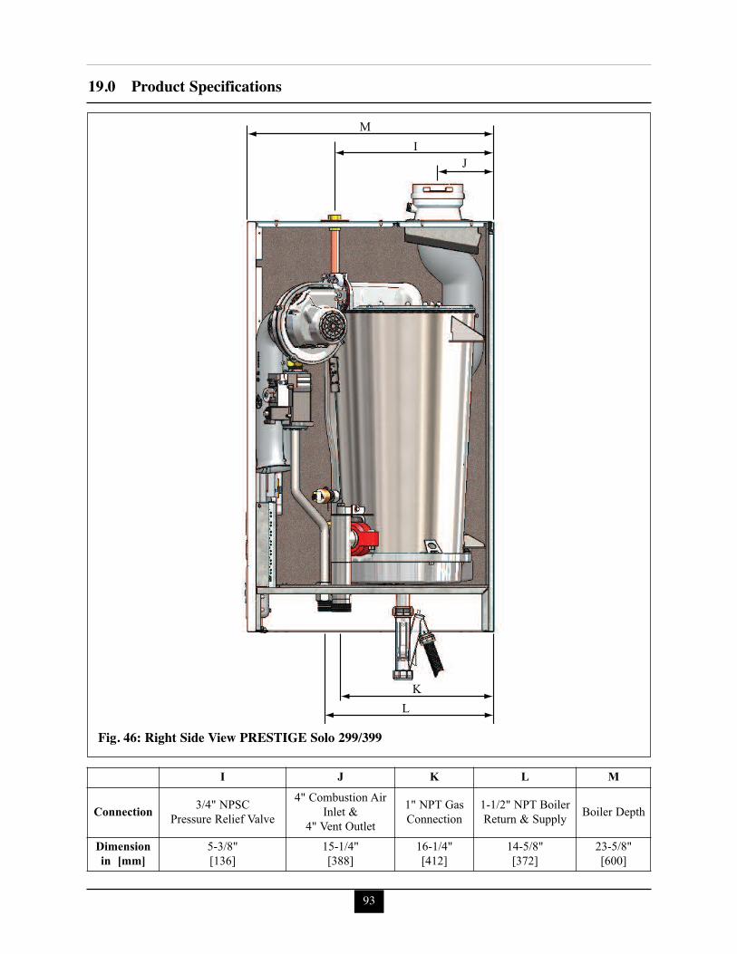
Section XIX Product SpecificationsPRESTIGE Solo 80/110 Front View ...............................................................................88PRESTIGE Solo 80/110 Right Side View.......................................................................89PRESTIGE Solo 155/175/250 Front View......................................................................90PRESTIGE Solo 155/175/250 Right Side View .............................................................91PRESTIGE Solo 299/399 Front View.............................................................................92PRESTIGE Solo 299/399 Right Side View.....................................................................93
Section XX NotesGeneral Notes .........................................................................................................97
Product & Safety Information
1
Indicates the presence of a hazardoussituation which, if ignored, will result indeath, serious injury or substantialproperty damage.
Indicates a potentially hazardous situa-tion which, if ignored, can result indeath, serious injury or substantialproperty damage.
Indicates a potentially hazardous situa-tion which, if ignored, may result inminor injury or property damage.
Indicates special instructions on installa-tion, operation or maintenance, whichare important to equipment but notrelated to personal injury hazards.
Indicates recommendations made byACV-Triangle Tube for the installerswhich will help to ensure optimum oper-ation and longevity of the equipment
NOTICE
WARNING
CAUTION
BEST PRACTICE
DANGER
The following terms are used throughout this manual to bring attention to the presence ofpotential hazards or important information concerning the product.
ACV-Triangle Tube reserves the right to modify the technical specifications and compo-nents of its products without prior notice.
NOTICE
PRODUCT & SAFETY INFORMATION
Definitions
2
Product & Safety Information
Do not use this appliance if any part hasbeen under water. Immediately call aqualified service technician to inspectthe appliance and to replace any part ofthe control system which has beenunder water.
WHAT TO DO IF YOU SMELL GAS- Do not try to light any appliance- Do not touch any electrical switch; donot use any phone in your building.
- Immediately call your gas supplierfrom a neighbor’s phone. Follow thegas supplier’s instructions.
- If you cannot reach your gas suppli-er, call the fire department.
Installation and service must be per-formed by a qualified installer, serviceagency or the gas supplier.
Should overheating occur or the gassupply fails to shut off, turn OFF themanual gas control valve external to theappliance.
DO NOT add cold make up water whenthe appliance is hot. Thermal shock canpotentially cause cracks in the heatexchanger.
When servicing the appliance:- Avoid electrical shock by discon-necting the electrical supply prior toperforming maintenance.
Qualified Installer:Prior to installing this product read all instruc-tions included in this manual and all accompa-nying manuals/documents with this appliance.Perform all installation steps required in thesemanuals in the proper order given. Failure toadhere to the guidelines within these manualscan result in severe personal injury, death orsubstantial property damage.
Homeowner:- This product should be maintained /serviced and inspected annually by aqualified service technician.
- This manual is intended for use by aqualified Installer/Service Technician.
Please reference the unit’s model numberand the serial number from the rating labelwhen inquiring about service or trou-bleshooting.
ACV-Triangle Tube accepts no liability forany damage, injury or loss of life resultingfrom incorrect installation, from alter-ation of any factory supplied parts or fromthe use of parts or fittings not specified byACV-Triangle Tube. If there is a conflictor doubt about the proper installation ofthe unit or any factory supplied orreplacement parts please contact ACV-Triangle Tube Technical Support.
A byproduct of any gas fired applianceis carbon monoxide. In the absence ofany state or local codes requiring theinstallation of carbon monoxide detec-tor and alarms, ACV-Triangle Tube’srecommendation is to follow therequirements of the Commonwealth ofMassachusetts, see page 11.
WARNING
WARNING
WARNING
CAUTION
DANGER WARNING
NOTICE
WARNING
WARNING
1.0 Pre-Installation Items
3
SECTION I - PRE-INSTALLATIONITEMS1.1 Code ComplianceThis product must be installed in accordance tothe following:
- All applicable local, state, national andprovincial codes, ordinances, regula-tions and laws.
- For installations in Massachusetts, coderequires the boiler to be installed by alicensed plumber or gas fitter, and ifantifreeze is utilized, the installation ofa reduced pressure backflow preventerdevice is required in the boiler’s coldwater fill or make up water supply line.
- For installation in Massachusetts all directvented appliances must comply with theguidelines as outlined on page 11.
- The National Fuel Gas Code NFPA54/ANSI Z 223.1 - Latest edition.
- National Electric Code ANSI/NFPA 70.- For installations in Canada -“Installation
Code for Gas Burning Equipment”CGA/B149.1 or B149.2 CanadianElectrical Code Part 1 CSA C22.1.
- Standards for Controls and SafetyDevices for Automatically Fired Boilers,ANSI/ASME CSD-1, when required.
The PRESTIGE Solo boiler gas manifoldand gas controls meet the safe lighting andother performance requirements as speci-fied in ANSI Z21.13 latest edition.
1.2 Determining Product Location
The PRESTIGE boiler is certified forindoor, conditioned space installationsONLY.
Before locating the PRESTIGE SOLO checkfor convenient locations to:
- Heating system piping- Venting - Gas supply piping- Electrical service
Ensure the boiler location allows the combus-tion air/vent piping to be routed directly throughthe building and terminate properly outside witha minimum amount of length and bends.Ensure the area chosen for the installation of thePRESTIGE Solo is free of any combustiblematerials, gasoline and other flammable liquids.
Failure to remove or maintain the areafree of combustible materials, gasolineand other flammable liquids or vaporscan result in severe personal injury,death or substantial property damage.
Ensure the PRESTIGE Solo and its controlsare protected from dripping or spraying waterduring normal operation or service.
The PRESTIGE Solo should be installed in alocation so that any water leaking from theboiler or piping connections or relief valve willnot cause damage to the area surrounding theunit or any lower floors in the structure.
1.3 Boiler ReplacementIf the PRESTIGE Solo is replacing an existingboiler, the following items should be checkedand corrected prior to installation:
- Boiler piping leaks and corrosion.- Improper location and sizing of the
expansion tank on the boiler heatingloop.
- If applicable, level and quality ofantifreeze within the boiler system.
NOTICE
WARNING
NOTICE
1.0 Pre-Installation Items1.4 Recommended ClearancesThe PRESTIGE Solo is approved for zeroclearance to combustibles, excluding vent andboiler piping.
- Boiler Piping - 1/4 inch from com-bustible materials.
- Reference the appropriate vent supple-ment for clearance requirements.
To provide serviceability to the unit it isrecommended that the following clear-ances be maintained:Top boiler jacket - 24 inches [610 mm].Front - 24 inches [610 mm].Bottom boiler piping - 24 inches [610 mm].Rear - 0 inchesSides - 6 inches [153 mm]
If the clearances listed above cannot bemaintained or the enclosure in which theboiler is installed is less than 85 cubic feet,the space must be ventilated. See page 6for ventilation requirements.
When maintaining less than recom-mended serviceability clearances, someproduct labeling, including the ratinglabel, may become hidden and unread-able.
When installing the PRESTIGE Solo ina confined space, sufficient air must beprovided for proper combustion andventing and to allow, under normal oper-ating conditions, proper air flow aroundthe product to maintain ambient temper-atures within safe limits to comply withthe National Fuel Gas Code NFPA 54 -latest edition.
1.5 Residential Garage InstallationsWhen installing the PRESTIGE Solo in a resi-dential garage, the following special precautionsper NFPA 54/ANSI Z223.1 must be taken:
- Mount the unit a minimum 18 inches[458 mm] above the floor level of thegarage. Ensure the burner and ignitiondevices / controls are no less than 18inches [458 mm] above the floor level.
- Locate or protect the unit in a manner so itcannot be damaged by a moving vehicle.
1.6 Boiler Freeze Protection FeatureThe ACVMax boiler management system has afreeze protection feature built in. This featuremonitors the boiler water temperature andresponds as follows when no call for heat is pre-sent:
- 46ºF [8ºC] Pump outputs configured torespond to a CH1 Call are enabled.
- 42ºF [6ºC] Pump outputs configured torespond to a CH1 or CH2 Call areenabled, Burner operates at low fire.
- 60ºF [15ºC] Freeze protection ends.Burner & all pumps turn off after com-pleting CH Post Pump Time.
The boiler freeze protection feature isdisabled during a hard lockout, howeverthe circulators will operate.
The boiler freeze protection feature isdesigned to protect the boiler. The boilershould be installed in a primary/sec-ondary piping arrangement if it isinstalled in an unheated space orexposed to water temperatures of 46ºF orless. See Section IV for primary/sec-ondary piping examples. See Section Xfor antifreeze guides.
NOTICE
WARNING
WARNING
CAUTION
CAUTION
BEST PRACTICE
4
2.0 Combustion Air & Venting
5
SECTION II - COMBUSTION AIRAND VENTING2.1 Combustion Air Contamination
If the PRESTIGE Solo combustion airinlet is located in any area likely to causeor contain contamination, or if products,which would contaminate the air cannotbe removed, the combustion air must berepiped and terminated to another loca-tion. Contaminated combustion air willdamage the unit and its burner system,resulting in possible severe personalinjury, death or substantial propertydamage.
Do not operate a PRESTIGE Solo if itscombustion air inlet is located near alaundry room or pool facility. Theseareas will always contain hazardous con-taminants.Pool and laundry products and commonhousehold and hobby products oftencontain fluorine or chlorine compounds.When these chemicals pass through theburner and vent system, they can formstrong acids. These acids can create cor-rosion of the heat exchanger, burnercomponents and vent system, causingserious damage and presenting a possi-ble threat of flue gas spillage or waterleakage into the surrounding area.Please read the information listed below.If contaminating chemicals are locatednear the area of the combustion air inlet,the installer should pipe the combustionair inlet to an outside area free of thesechemicals per SECTION V of thisinstallation manual.
bons- Permanent Wave Solutions- Chlorinated wax - Chlorine - based swimming pool chem-
icals / cleaners- Calcium Chloride used for thawing ice- Sodium Chloride used for water soft-
ening- Refrigerant leaks- Paint or varnish removers- Hydrochloric acid / muriatic acid- Cements and glues- Antistatic fabric softeners used in
clothes dryers- Chlorine-type bleaches, detergents, and
cleaning solvents found in householdlaundry rooms
- Adhesives used to fasten building prod-ucts and other similar products
Areas likely to contain these products- Dry cleaning / laundry areas and estab-
lishments- Beauty salons- Metal fabrication shops- Swimming pools and health spas- Refrigeration Repair shops- Photo processing plants- Auto body shops- Plastic manufacturing plants- Furniture refinishing areas and estab-
lishments- New building construction- Remodeling areas- Garages with workshops
WARNING
WARNING
6
2.0 Combustion Air Venting
2.2 Ventilation and Combustion Air Requirements - Direct Vent
A Direct Vent appliance utilizes uncontaminat-ed outdoor air (piped directly to the appliance)for combustion.For Direct Vent installations, involving onlythe PRESTIGE Solo, in which the minimumservice clearances are maintained as listed onpage 4, no ventilation openings are required.For Direct Vent, zero clearance installationsinvolving only the PRESTIGE Solo, the space/ enclosure must provide two openings for ven-tilation. The openings must be sized to provide1 square inch of free area per 1,000 BTUH ofboiler input. The openings shall be placed 12inches from the top of the space and 12 inchesfrom the floor of the space.For installations in which the PRESTIGE Soloshares the space with air movers (exhaust fan,clothes dryers, fireplaces, etc.) and other com-bustion equipment (gas or oil) the space mustbe provided with adequate air openings to pro-vide ventilation and combustion air to theequipment. To properly size the ventilation /combustion air openings, the installer mustcomply with the National Fuel Gas CodeNFPA 54, ANSI Z223.1 for installations in theU.S or CSA B149.1 and B149.2 for installa-tions in Canada.
The space must be provided with venti-lation / combustion air openings proper-ly sized for all make-up air requirements(exhaust fans, clothes dryers, fireplaces,etc.) and the total input of all applianceslocated in the same space as the PRES-TIGE Solo, excluding the input of aDirect Vent PRESTIGE Solo which usescombustion air directly from the outside,thus additional free area for the open-ings is not required. Failure to provideor properly size the openings couldresult in severe personal injury, death orsubstantial property damage.
2.3 Ventilation and Combustion Air Requirements - Category IV
A Category IV appliance utilizes uncontami-nated indoor or outdoor air (surrounding theappliance) for combustion.
In order to reduce the potential risksassociated with indoor contaminates(listed on page 5), flammable vapors andtight housing construction (little or noinfiltration air), it is recommended topipe uncontaminated combustion airdirectly from the outdoors to the appli-ance. This practice also promotes highersystem efficiency by reducing heatedindoor air from being exhausted fromthe house and replaced by cold infiltra-tion air into the house.
For installations in which the PRESTIGE Soloshares the space with air movers (exhaust fan,clothes dryers, fireplaces, etc.) and other com-bustion equipment (gas or oil) the space must beprovided with adequate air openings to provideventilation and combustion air to the equipment.To properly size the ventilation / combustion airopenings, the installer must comply with theNational Fuel Gas Code NFPA 54, ANSI Z223.1for installations in the U.S or CSA B149.1 andB149.2 for installations in Canada, as referencedin this section of the manual and titled Methodsof Accessing Combustion Air into a Space.
The space must be provided with venti-lation / combustion air openings proper-ly sized for all make-up air requirements(exhaust fans, clothes dryers, fireplaces,etc.) and the total input of all appliances,including the PRESTIGE Solo whenlocated in the same space. Failure to pro-vide or properly size the openings couldresult in severe personal injury, death orsubstantial property damage.
WARNING
WARNING
BEST PRACTICE
7
2.0 Combustion Air Venting2.4 Methods of Accessing Combustion
Air Into A Space - Category IV
2.4.1 Indoor Combustion Air
The methods listed in this section foraccessing Indoor Combustion Airassume that the infiltration rate is ade-quate and not less than .40 ACH. Forinfiltration rates less than .40 ACH, ref-erence the NFPA 54 National Fuel GasCode for additional guidance.
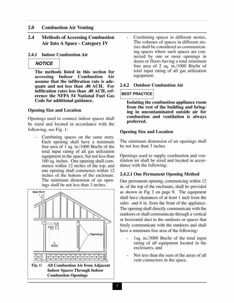
Opening Size and LocationOpenings used to connect indoor spaces shallbe sized and located in accordance with thefollowing, see Fig. 1:
- Combining spaces on the same story.Each opening shall have a minimumfree area of 1 sq. in./1000 Btu/hr of thetotal input rating of all gas utilizationequipment in the space, but not less than100 sq. inches. One opening shall com-mence within 12 inches of the top, andone opening shall commence within 12inches of the bottom of the enclosure.The minimum dimension of air open-ings shall be not less than 3 inches.
- Combining spaces in different stories.The volumes of spaces in different sto-ries shall be considered as communicat-ing spaces where such spaces are con-nected by one or more openings indoors or floors having a total minimumfree area of 2 sq. in./1000 Btu/hr oftotal input rating of all gas utilizationequipment.
2.4.2 Outdoor Combustion Air
Isolating the combustion appliance roomfrom the rest of the building and bring-ing in uncontaminated outside air forcombustion and ventilation is alwayspreferred.
Opening Size and LocationThe minimum dimension of air openings shallbe not less than 3 inchesOpenings used to supply combustion and ven-tilation air shall be sized and located in accor-dance with the following: 2.4.2.1 One Permanent Opening Method One permanent opening, commencing within 12in. of the top of the enclosure, shall be providedas shown in Fig 2 on page 8. The equipmentshall have clearances of at least 1 inch from thesides and 6 in. from the front of the appliance.The opening shall directly communicate with theoutdoors or shall communicate through a verticalor horizontal duct to the outdoors or spaces thatfreely communicate with the outdoors and shallhave a minimum free area of the following:
- 1sq. in./3000 Btu/hr of the total inputrating of all equipment located in theenclosures, and
- Not less than the sum of the areas of allvent connectors in the space.
NOTICE
BEST PRACTICE
All Combustion Air from AdjacentIndoor Spaces Through IndoorCombustion Openings
Fig. 1:
8
2.0 Combustion Air Venting
2.4.2.2 Two Permanent Openings Method Two permanent openings, one commencingwithin 12 in. of the top and one commencingwithin 12 in. of the bottom of the enclosure,shall be provided. The openings shall commu-nicate directly, or by ducts, with the outdoorsor spaces that freely communicate with the out-doors, as follows:
- Where directly communicating with theoutdoors or where communication to theoutdoors is through vertical ducts, eachopening shall have a minimum free areaof 1 sq. in./4000 Btu/hr of total input rat-ing of all equipment in the enclosure.See Fig.3.
- Where communicating with the out-doors is through horizontal ducts, eachopening shall have a minimum freearea of not less than 1 sq.in./2000Btu/hr of total input rating of all equip-ment in the enclosure. See Fig. 4.
All Combustion Air from OutdoorsThrough One Permanent AirOpening
Fig. 2: All Combustion Air from OutdoorsThrough Ventilated Attic
Fig. 3:
All Combustion Air from OutdoorsThrough Horizontal Ducts
Fig. 4:
9
2.0 Combustion Air Venting2.4.3 Combination of Indoor and
Outdoor Combustion Air
Indoor Openings: Where used, openings con-necting the interior spaces shall comply withthe Indoor Combustion Air section on page 7.
Outdoor Opening(s) Location. Outdoor open-ing(s) shall be located in accordance with theOutdoor Combustion Air section.
Outdoor Opening(s) Size. Outdoor opening(s) shallbe calculated in accordance with the following:
- The ratio of the interior spaces shall bethe available volume of all communi-cating spaces divided by the requiredvolume.
- The outdoor size reduction factor shallbe 1 minus the ratio of interior spaces.
- The minimum size of outdoor open-ing(s) calculated in accordance with theabove outdoor air section multiplied bythe reduction factor. The minimumdimension of air openings shall not beless than 3 in.
Do not install the PRESTIGE Solo into acommon vent with other gas or oil appli-ances. This may cause flue gas spillage orappliance malfunction, resulting in possi-ble severe personal injury, death or sub-stantial property damage.
2.5 Combustion Air and Vent PipingThe PRESTIGE Solo requires a Category IVventing system, which is designed for pressur-ized venting and condensate.The PRESTIGE Solo is certified per ANSIZ21.13 as a Category IV or Direct Vent (sealedcombustion) appliance. A Category IV appli-ance utilizes uncontaminated indoor or outdoorair (surrounding the appliance) for combustion.A Direct Vent appliance utilizes uncontaminat-
ed outdoor air (piped directly to the appliance)for combustion.
In order to reduce the potential risksassociated with indoor contaminates(listed on page 5), flammable vaporsand tight housing construction (little orno infiltration air), it is recommendedto pipe uncontaminated combustion airdirectly from the outdoors to the appli-ance. This practice also promotes highersystem efficiency by reducing heatedindoor air from being exhausted fromthe house and replaced by cold infiltra-tion air into the house.
Install combustion air and vent pipe asdetailed in the PRESTIGE Solo VentSupplement included in the boilerinstallation envelope. Refer to optionalvent kit instructions for additional ventinstallation instructions.
Verify installed combustion air and ventpiping are sealed gas tight and meet allprovided instructions and applicablecodes, failure to comply will result insevere personal injury of death.
NOTICE
BEST PRACTICE
DANGERDANGER
10
2.0 Combustion Air Venting2.6 Removal of an Existing Boiler
from a Common Vent System
When an existing boiler is removed from acommon venting system, the common ventingsystem is likely to be too large for properventing of the remaining appliances. At thetime of removal of an existing boiler, the fol-lowing steps shall be followed with eachappliance remaining connected to the com-mon venting system placed in operation,while the other appliances remaining con-nected to the common venting system are notin operation.1. Seal any unused openings in the common
venting system.2. Visually inspect the venting system for
proper size and horizontal pitch and deter-mine there is no blockage or restriction,leakage, corrosion and other deficiencieswhich could cause an unsafe condition.
3. Insofar as is practical, close all buildingdoors and windows and all doors betweenthe space in which the appliances remain-ing connected to the common venting sys-tem are located and other spaces of thebuilding. Turn on clothes dryers and anyappliance not connected to the commonventing system. Turn on any exhaust fans,such as range hoods and bathroomexhausts, so they will operate at maximumspeed. Do not operate a summer exhaustfan. Close fireplace dampers.
4. Place in operation the appliance beinginspected. Follow the lighting instructions.Adjust thermostat so appliance will operatecontinuously.
5. Test for spillage at the draft hood reliefopening after 5 minutes of main burneroperation. Use the flame of a match or can-dle, or smoke from a cigarette, cigar or pipe.
6. After it has been determined that eachappliance remaining connected to the com-mon venting system properly vents whentested as outlined above, return doors, win-dows, exhaust fans, fireplace dampers, andany other gas-burning appliance to theirprevious condition of use.
7. Any improper operation of the commonventing system should be corrected so theinstallation conforms with the NationalFuel Gas Code, ANSI Z223.1/NFPA 54and/or CAN/CGA B149, Installation codes.When resizing any portion of the commonventing system, the common venting sys-tem should be resized to approach the min-imum size as determined using the appro-priate tables in Part II of the National FuelGas Code ANSI Z223.1/NFPA 54 and/orCAN/CGA B149, Installation codes.
Do not install the PRESTIGE Solo into acommon vent with other gas or oil appli-ances. This may cause flue gas spillage orappliance malfunction, resulting in possi-ble severe personal injury, death or sub-stantial property damage.
DANGER
BEST PRACTICE
11
2.0 Combustion Air Venting
For direct-vent appliances, mechanical-vent heating appliances or domestic hotwater equipment, where the bottom of thevent terminal and the air intake is installedbelow four feet above grade the followingrequirements must be satisfied:
1. If there is not one already present, oneach floor level where there are bed-room(s), a carbon monoxide detectorand alarm shall be placed in the livingarea outside the bedroom(s). The car-bon monoxide detector shall complywith NFPA 720 (2005 Edition).
2. A carbon monoxide detector shall alsobe located in the room that houses theappliance or equipment and shall:
a. Be powered by the same electrical cir-cuit as the appliance or equipment suchthat only one service switch servicesboth the appliance and the carbonmonoxide detector;
b. Have battery back-up power;c. Meet ANSI/UL 2034 Standards andcomply with NFPA 720 (2005 Edition);and
d.Have been approved and listed by theNationally Recognized TestingLaboratory as recognized under 527CMR.
3. A Product-approved vent terminal mustbe used, and if applicable, a Product-approved air intake must be used.Installation shall be in strict compliancewith the manufacturer’s instructions. Acopy of the installation instructionsshall remain with the appliance orequipment at the completion of theinstallation.
4. A metal or plastic identification plateshall be mounted at the exterior of thebuilding, four feet directly above thelocation of vent terminal. The plateshall be of sufficient size to be easilyread from a distance of eight feet away,and read “Gas Vent Directly Below”.
Installer must provide tag identificationplate and ensure the lettering meets coderequirements.For direct-vent appliances, mechanical-vent heating appliances or domestic hotwater equipment, where the bottom of thevent terminal and the air intake are installedabove four feet above grade the followingrequirements must be satisfied:1. If there is not one already present, on
each floor level where there are bed-room(s), a carbon monoxide detectorand alarm shall be placed in the livingarea outside the bedroom(s). The car-bon monoxide detector shall complywith NFPA 720 (2005 Edition).
2. A carbon monoxide detector shall: a. Be located in the room that houses theappliances or equipment;
b.Be either hard wired or battery poweredor both; and
c. Shall comply with NFPA 720 (2005Edition)
3. A Product-approved vent terminal mustbe used, and if applicable, a Product-approved air intake must be used.Installation shall be in strict compliancewith the manufacturer’s instructions. Acopy of the installation instructionsshall remain with the appliance orequipment at the completion of theinstallation.
NOTICE
2.7 Commonwealth of Massachusetts Installations Only
12
3.0 Unit PreparationsSECTION III - UNITPREPARATIONS3.1 Handling InstructionsThe PRESTIGE Solo is generally easier tohandle and maneuver once removed from theshipping carton. To remove the shipping carton:
Use care not to drop, bump or rotate theboiler upside down, as damage to theboiler will result.
1. Remove any shipping straps and open theside of the shipping carton.
2. Slide the unit with the foam inserts out ofthe carton.
3. Discard all packing materials.
3.2 Wall Mounting InstallationThe PRESTIGE Solo should be wall mountedusing the bracket provided with the boiler. ThePRESTIGE Solo is not designed for floorinstallation. If floor installation is required anoptional floor stand is available through ACV-Triangle Tube.
The wall used for mounting the PRES-TIGE Solo must be vertically plumbedand capable of supporting a minimum130 pounds [59 kg] for the PRESTIGESolo 80/110, 175 pounds [80 kg] forPRESTIGE Solo 155/175/250 and 265pounds [120 Kg] for PRESTIGE Solo299/399. Failure to comply with theserequirements could result in personalinjury, death or substantial propertydamage.
3.3 Wall Mounting Guidelines1. The wall-mounting bracket is designed for
stud spacing of 12 inch or 16 inch on cen-ters. For unconventional stud spacing, asolid / secure mounting surface must beprovided for installation of the bracket.
2. For applications using wood studs, installthe bracket using the lag screws providedwith the boiler. Ensure both lag screws areinstalled securely in the studs.
3. For applications using metal studs, installthe bracket to the studs using 3/16” togglebolts and washers.
4. DO NOT mount or attempt to mount thewall bracket to hollow sheet rock or lathwalls using anchors. Only install boiler tostuds or equivalent wood structure.
5. For applications using solid walls (rock,concrete, brick, cinder block, etc.), installthe wall bracket using anchors (doubleexpansion shields) and bolts with washersprovided with the boiler.
6. The boiler is too heavy and bulky for a sin-gle person to lift and attempt to mount; aminimum of 2 people is required formounting the boiler.
Use extreme care not to drop the boileror cause bodily injury while lifting ormounting the boiler onto the bracket.Once mounted verify that the boiler issecurely attached to the bracket andwall. Failure to comply with the aboveguidelines could result in property dam-age, personal injury or death.
NOTICE
NOTICE
CAUTION
13
3.0 Unit Preparations
3.4 Stud Walls - Installation 3.4.1 PRESTIGE Solo 80/110/155/175/2501. Locate the studs in the general area of the
boiler placement.2. Place the wall-mounting bracket on the
wall centering the mounting slots with thestud centers and ensuring the upper edge ofthe bracket is away from the wall.
3. Level the bracket, while maintaining it’scentering with the studs and use a pencil tomark the location of the mounting slots.
4. Remove the bracket from the wall and drill1/4” diameter hole by 3” deep positioned inthe center of each mark. For applicationsusing metal studs and 3/16” toggle bolts,drill the required clearance hole.
5. Reposition the bracket onto the wall andalign mounting slots/holes. Insert the twolag screws provided (or toggle bolts formetal studs) through the mountingslots/holes and loosely tighten.
6. Level bracket and tighten screws (bolts formetal studs) securely making sure not toover-tighten to avoid damaging drywall orplaster.
3.4.2 PRESTIGE Solo 299/399 1. To distribute the weight of the boiler even-
ly when mounting onto a stud wall it is rec-ommended to use the PRESTIGE SoloWall Frame kit.
2. When using the wall frame to mount theboiler reference the kit installation instruc-tions and ensure the frame is securely fas-tened to the wall.
3. If the structure of the wall is questionablein supporting a minimum weight of 265pounds [120 kg.], it is recommended to usethe optional floor stand.
3.5 Wall Bracket Installation - SolidWalls1. Locate the general area of the boiler place-
ment.2. Place the wall-mounting bracket on the
wall ensuring the upper edge of the bracketis away from the wall.
3. Level the bracket and use a pencil to markthe location of the mounting slots on thewall.
4. Remove the bracket from the wall and drilla 5/8” diameter hole by 1-3/8” deep posi-tioned in the center of each mark.
5. Install the anchors (provided) flush orslightly recessed in the drilled holes withthreaded side facing down.
6. Reposition the bracket on the wall andalign mounting slots/holes. Insert the twobolts (provided) through the mountingslots/holes and loosely tighten.
7. Level bracket and tighten bolts securely.
3.6 Boiler Mounting1. Obtain assistance in lifting the boiler onto
the wall bracket.2. Install the boiler making sure the boiler
mounting lip located along the upper edgeof the rear jacket panel engages the wall-mounting bracket. Ensure the boiler isseated properly and is secure.
4.0 Boiler Piping
SECTION IV - BOILER PIPING4.1 General Piping Requirements- All plumbing must meet or exceed all local,
state and national plumbing codes.- Support all piping using hangers. DO NOT
support piping by the unit or its components.- Use isolation valves to isolate system com-
ponents.- Install unions for easy removal of the
PRESTIGE Solo from the system piping.
Use a two wrench method when tighten-ing piping onto the boiler connections.Use one wrench to prevent the boilerpiping from turning / twisting. Failureto support the boiler piping and connec-tions in this manner could cause damageto the boiler and its components.
4.2 Pressure Relief Valve1. The PRESTIGE Solo is supplied with a 30
psi pressure relief valve and must be pipedusing the PRV connection as shown in Fig.5 page 15.
2. To avoid potential water damage to the sur-rounding area or potential scalding hazarddue to the operation of the relief valve, thedischarge piping:- Must be connected to the discharge out-
let of the relief valve and directed to asafe place of disposal.
- Length should be as short and direct aspossible. The size of the discharge lineshould not be reduced, maintain thesame size as the outlet of the relief valve.
- Should be directed downward towardsthe floor at all times. The piping shouldterminate at least 6 inches [153 mm]above any drain connection to allowclear visibility of the discharge.
- Should terminate with a plain end, notwith a threaded end. The material ofthe piping should have a serviceabletemperature rating of 250ºF or greater.
- Should not be subject to conditionswhere freezing could occur.
- Should not contain any shut-off valvesor obstructions. No shut-off valveshould be piped between the boiler andrelief valve.
Failure to comply with the guidelines oninstalling the pressure relief valve anddischarge piping can result in personalinjury, death or substantial propertydamage.
4.3 Boiler Air Vent
This boiler is supplied with a specialautomatic air vent that will provide reli-able operation in purging air from theboiler. The hygroscopic cap suppliedwith the automatic air vent MUSTremain tight at all times on the air ventbody. The hygroscopic cap has a mem-brane which expands upon contact withwater and seals the air vent until themembrane dries up due to new air form-ing in the air vent.
1. Make sure to fully tighten the cap on the airvent on initial installation.
2. Never loosen the hygroscopic cap to allowair to escape the air vent. Air will exit withthe cap fully tightened in place.
3. If the hygroscopic cap is not fully tight-ened, water may leak from the cap. Simplytighten the cap securely.
WARNING
WARNING
NOTICE
14
15
4.0 Boiler Piping
4.4 Low Water Cutoff Device- The PRESTIGE Solo is equipped with a fac-
tory installed pressure sensor type Low WaterCut Off device.
- The minimum operating system pressureallowable with this device is 10 psig.
- Check local codes if a Low Water CutoffDevice is required. If so, determine if thisdevice meets the requirements of the localcodes.
The PRESTIGE Solo control system alsosenses the water temperatures enteringand exiting the heat exchanger to pro-vide protection against low water condi-tions. Where local codes and jurisdic-tion do not accept a pressure device forlow water protection, the jurisdictionsmay accept these PRESTIGE Solo inte-gral control functions as a means of pro-viding low water protection.
4.5 Additional Limit ControlIf a separate LWCO device is required by thelocal jurisdiction or when the boiler is installedabove the system piping, the following guide-lines must be followed:
- The LWCO device must be designedfor water installations, electrode probe-type is recommended.
- The LWCO device must be installed ina tee connection on the boiler supplypiping above the boiler.
- Wiring of the LWCO device to the PRES-TIGE Solo is done directly onto the lowvoltage terminal strip, reference Fig. 19page 31 for available terminals for anexternal limit (manual or auto reset).
If the installation is to comply with ASME orCanadian requirements, an additional hightemperature limit may be needed. Consultlocal code requirements to determine compli-ance. The limit should be installed as follows:
- Install the limit in the boiler supply pip-ing between the boiler and any isolationvalve.
NOTICE
Fig. 5: Pressure Relief Valve and Boiler Drain Valve Installation
4.0 Boiler Piping- Consult heat exchanger for maximum
set point of limit.- For wiring of the limit, reference Fig. 19,
page 31, using the external manual resetterminals on the low voltage terminalstrip. This will provide a "hard" lockoutrequiring a manual reset of the control.
4.6 Backflow Preventer- Use a backflow preventer valve in the
make-up water supply to the unit asrequired by local codes.
4.7 Boiler System Piping Applications
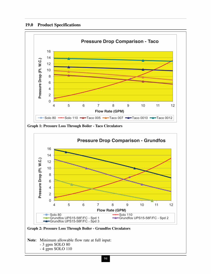
It is recommended on all piping applica-tions to utilize a primary/secondary pip-ing arrangement as a means to providefreeze protection of the boiler, which is anintegral function of the boiler control.Maintain the minimum boiler flow rateshown in Graphs 1 through 6 on pages 94through 96. For other piping arrange-ments, contact ACV-Triangle TubeTechnical Support or consult otherapproved/recognized design arrange-ments.
On piping applications utilizing a singlezone or other recognized piping designarrangements, it is recommended that theinstaller uses flow/check valves withweighted seats at or near the appliance toprevent gravity circulation.
4.8 Expansion Tank and MakeupWaterEnsure the expansion tank is properly sized forthe boiler volume (3 gallons [12 L] for thePRESTIGE Solo 80/110, 5 gallons [19 L] forthe PRESTIGE Solo 155/175/250, 7 gallons[26 L] for PRESTIGE Solo 299/399) and thesystem volume and temperature.
Undersized expansion tanks will causesystem water to be lost through the pres-sure relief valve and cause additionalmakeup water to be added to the system.Eventual boiler heat exchanger failurecan result due to this excessive makeupwater addition.
The expansion tank must be located as shownin Fig. 7 and Fig. 8 on page 18 when using aprimary/secondary piping arrangement or asper recognized design methods. Refer to theexpansion tank manufacturer instructions foradditional installation details.Connect the expansion tank to an air separatoronly if the air separator is located on the suc-tion side (inlet) of the system circulator.Always locate and install the system fill con-nection at the same location as the expansiontank connection to the system.
4.8.1 Diaphragm Expansion TankAlways install an automatic air vent on the topof the air separator to remove residual air fromthe system.
4.8.2 Closed-Type Expansion TankIt is recommended to pitch any horizontal pipingupwards toward the expansion tank 1 inch per 5feet of piping. Use 3/4” piping for the expansiontank to allow air within the system to rise.
DO NOT install automatic air vents on aclosed-type expansion tank system. Airmust remain in the system and bereturned to the expansion tank to pro-vide an air cushion. An automatic airvent would cause air to be vented fromthe system resulting in a water-loggedexpansion tank.
BEST PRACTICE
BEST PRACTICE
CAUTION
CAUTION
16
4.0 Boiler Piping
17
Fig. 6: Piping Component Legend
BoilerSupply
BoilerReturn
SystemSupply
ColdWater
Fill
SystemReturn
12" Max.
BoilerSupply
BoilerReturn
SystemSupply
ColdWater
Fill
SystemReturn
12" Max.
Minimum ¾” Piping
Fig. 8 : Near Boiler Piping - Closed Type Expansion Tank
Fig. 7: Near Boiler Piping - Diaphragm Expansion Tank
Note: Pitch horizontal pipingupwards (1” of pitch per 5 ftof piping) towards expansiontank.
18
4.0 Boiler Piping
19
4.0 Boiler Piping
4.9 CirculatorThe PRESTIGE Solo requires an external circula-tor to provide circulation through the boiler. Thecirculator, when wired directly to the PRESTIGESolo, will allow for domestic hot water priorityand provide circulation for the freeze protectionfeature of the boiler control. See Graphs 1 through6 on pages 94 through 96 for pressure drop andminimum flow rate through the boiler.
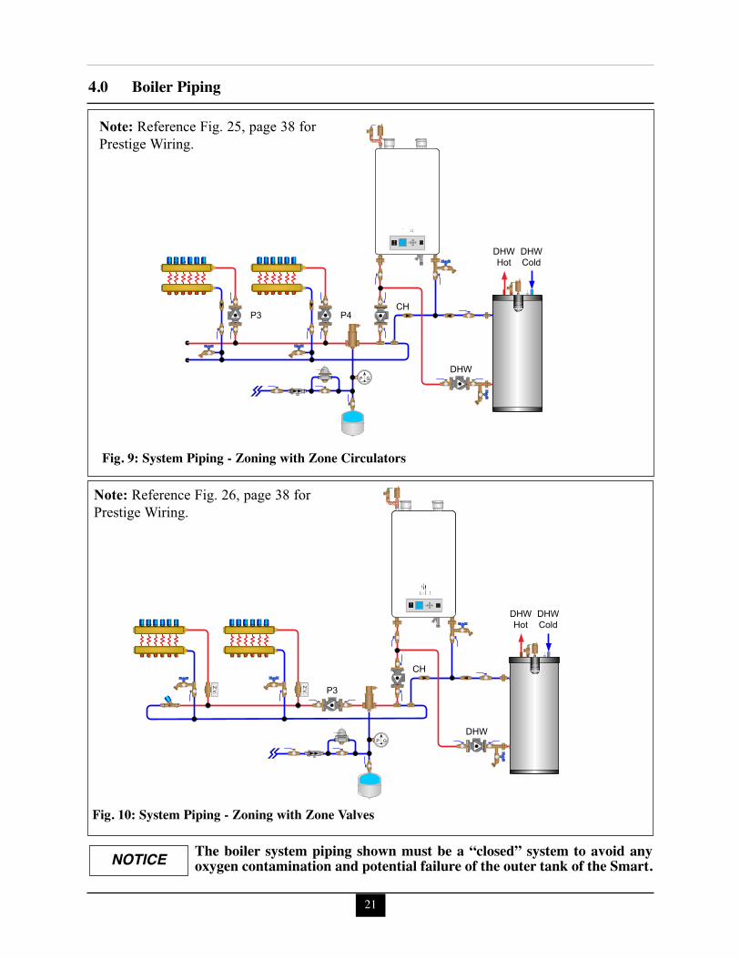
4.10 Sizing Primary PipingSee Fig. 9 through 13, pages 21 - 23, for rec-ommended piping arrangements based on vari-ous applications. Size the piping and systemcomponents required in the space heating sys-tem using recognized design methods. 4.11 Domestic Hot Water System PipingSee Fig. 9 through 12 on pages 21-22 for recom-mended piping to a DHW system. This recom-mended piping configuration ensures priority isgiven to the production and recovery of the DHW.The piping for the DHW is separate from theboiler system piping and does not require a pri-mary / secondary piping configuration.To wire the DHW circulator to the boiler controlmodule, reference Section VIII - External Wiring.4.12 System Piping - Zone CirculatorsConnect the PRESTIGE Solo to the systempiping as shown in Fig. 9 on page 21 when zon-ing with zone circulators. The installer must provide a separate circulatorfor each zone of space heating as well as theboiler circulator.
To ensure an adequate flow rate throughthe PRESTIGE Solo, the boiler supply andreturn piping size must be a minimum of 1inch for the PRESTIGE Solo 80/110, 1-1/4inch for the PRESTIGE Solo 155/175/250and 1-1/2 inch for the PRESTIGE Solo299/399.
4.13 System Piping - Zone ValvesConnect the PRESTIGE Solo to the system pip-ing as shown in Fig. 10 on page 21 when zoningwith zone valves. The primary / secondary pipingensures that the boiler loop has sufficient flow.
To ensure an adequate flow rate throughthe PRESTIGE Solo, the boiler supplyand return piping size must be a minimumof 1 inch for the PRESTIGE Solo 80/110,1-1/4 inch for the PRESTIGE Solo155/175/250 and 1-1/2 inch for the PRES-TIGE Solo 299/399.
4.14 System Piping - Through BoilerIn applications in which primary/secondaryarrangement is not utilized, the PRESTIGE Soloallows this flexibility due to a lower boiler pres-sure drop, see Graphs 1 through 6 on pages 94through 96.Figure 11 on page 22 illustrates a multiple zonevalve system with a single system/boiler circula-tor. A by-pass loop with a pressure differentialvalve must be installed on the system piping.Figure 12 on page 22 illustrates a single zone uti-lizing the boiler circulator as the system circulator.
4.15 System Piping - Radiant HeatingThe heat exchanger design of the PRESTIGEallows operation in a condensing mode. Thisfeature requires no regulation of the return tem-
NOTICE
NOTICE
20
4.0 Boiler Pipingperature back to the boiler in radiant heatingapplications.The design and construction of the PRESTIGEheat exchanger allows the installation of the boil-er on systems with non - oxygen barrier tubing.
DO NOT install a SMART tank alongwith the PRESTIGE in systems withnon-oxygen barrier tubing. Failure tocomply could result in premature failureof the SMART tank.
The boiler water supply temperature can bemaintained by the PRESTIGE, eliminatingthe need for a mix system to achieve thedesired temperature.It is recommended for the installer to install ahigh temperature limit to ensure that the pri-mary supply temperature does not exceed themaximum allowable temperature for the radi-ant tubing.Size the system piping and circulator to pro-vide the flow needed for the radiant system.
To ensure an adequate flow rate throughthe PRESTIGE Solo, the boiler supplyand return piping size must be a mini-mum of 1 inch for the PRESTIGE Solo80/110, 1-1/4 inch for the PRESTIGE Solo155/175/250 and 1-1/2 inch for the PRES-TIGE Solo 299/399.
The addition of the high temperature limitis important if the PRESTIGE is connect-ed to a domestic hot water system, whichrequires a high primary supply watertemperature.
4.16 System Piping - SpecialApplicationIf the boiler is used in conjunction with achilled water/medium system, the boiler andchiller must be piped in parallel. Installflow/check valves to prevent the chilled medi-um from entering into the boiler.If the boiler is used to supply hot water to theheating coils of an air handler where they maybe exposed to chilled air circulation, installflow/check valves or other automatic meansto prevent gravity circulation of the boilerwater during cooling cycles.
4.17 System Piping - Multiple UnitsInstallationUse a balanced manifold system as the prima-ry / secondary connection to the space heatingpiping as shown in Fig. 13 page 23.Maintain a minimum of 6 inches [153 mm] ofclearance between units to allow for servicing.For the space heating piping refer to the appli-cations mentioned in this manual or use recog-nized design methods.
NOTICE
NOTICE
CAUTION
21
4.0 Boiler Piping
smart
P G
P3 P4CH
DHW
DHWHot
DHWCold
smart
P G
Z.V.
Z.V.
DHW
P3
CH
DHWHot
DHWCold
Fig. 9: System Piping - Zoning with Zone Circulators
Fig. 10: System Piping - Zoning with Zone Valves
The boiler system piping shown must be a “closed” system to avoid anyoxygen contamination and potential failure of the outer tank of the Smart.NOTICE
5.0 Installing Vent/Combustion Air & Condensate Drain
SECTION V - INSTALLING VENT/ COMBUSTION AIR &CONDENSATE DRAIN5.1 Installing Vent and Combustion Air
The PRESTIGE Solo must be vented andsupplied with combustion air as shown inthe PRESTIGE Solo Vent Supplement,included in the boiler installation enve-lope. Refer to optional vent kit instruc-tions for additional vent installationinstructions. Once installation is complet-ed, inspect the vent and combustion airsystem thoroughly to ensure systems areairtight and comply with the instructionsgiven in the venting supplement and arewithin all requirements of applicablecodes. Failure to comply with the installa-tion requirements on the venting andcombustion air piping will cause severepersonal injury or death.
5.2 Installing Condensate DrainAssembly1. Locate the condensate drain assembly and
ensure the metal washer is installed asshown in Fig. 14 on page 25.
The installer may want to fill the con-densate trap with water prior to assem-bling on the unit.
2. Install the condensate drain assembly on theboiler condensate drain by pushing the con-densate drain assembly up until it stops.
3. Tighten the condensate drain assemblyretaining nut with rubber seal.
Ensure installation of the condensatedrain assembly included the metal wash-er. Failure to comply could result in thetrap assembly dislocating from the boiler.
Ensure the condensate drain assemblycontains the plastic seated ball. Do notinstall the condensate drain assembly ifthe ball is lost or missing, replace theentire assembly.
4. Remove the compression nut and rubberseal from the condensate drain assemblydrain outlet.
5. Using 3/4” x 2’ flexible PVC tube provid-ed, slide the compression nut and rubberseal over the pipe
The use of 3/4” PVC or CPVC pipe isalso acceptable. If 3/4” pipe is useddeburr and chamfer pipe to allow mat-ing onto the drain assembly.
6. Thread the rubber seal into the compres-sion nut to ease installation of the pipe tothe drain assembly.
7. Seat the pipe onto the drain assembly andtighten the compression nut. Hand tightonly!
The installer may opt to use 13/16" IDtubing in lieu of rigid piping.
WARNING
WARNING
NOTICE
DANGER
NOTICE
NOTICE
25
5.0 Installing Vent/Combustion Air & Condensate Drain
The drain line materials must be anapproved material by the authority hav-ing jurisdiction. In absence of suchauthority, PVC and CPVC piping mustcomply with ASTM D1785 or D2845.The cement and primer used on the pip-ing must comply with ASME D2564 orF493. For installations in Canada, useCSA or ULC certified PVC or CPVCpipe, fittings and cement/primer.
8. Continue the pipe from the drain assemblyto a floor drain or condensate pump.
When selecting and installing a conden-sate pump, ensure the pump is approvedfor use with condensing boilers and fur-naces. The pump should be equippedwith an overflow switch to prevent prop-
erty damage from potential condensatespillage.
9. The PRESTIGE Solo will typically producea condensate that is considered slightlyacidic with a pH content below 3.0. Installa neutralizing filter if required by authorityhaving jurisdiction.
The condensate drain must remain filledand unobstructed and allow unrestrictedflow of condensate. The condensateshould not be subject to conditionswhere freezing could occur. If the con-densate is subjected to freezing orbecomes obstructed , it can leak, result-ing in potential water damage to the boil-er and surrounding area.
CAUTION
NOTICE
NOTICE
Flexible Tubing(or 3/4 PVC/ CPVC Piping
to Drain)
CompressionNut with Rubber Seal
Fill Plugwith VaccumBreak Port
CondensateDrain Assembly
Plastic Ball(Not shown)
Retaining Nut
Metal Washer
Fig. 14: Condensate Drain Assembly
26
6.0 Gas PipingSECTION VI - GAS PIPING6.1 Gas Supply Piping Connection
The gas supply piping must be installedin accordance to all applicable local,state and national codes and utilityrequirements.
1. Install a 1/2” NPT for PRESTIGE Solo80/110, 3/4” NPT for PRESTIGE Solo155/175/250 or 1” NPT for PRESTIGESolo 299/399 pipe union at the factory sup-plied gas nipple, for ease of service.
2. Install a manual shutoff valve in the gassupply piping as shown in Fig. 15. Forinstallations in Canada the installer musttag and identify the main shutoff valve.
3. Install a sediment trap (drip leg) on the gassupply line prior to connecting to the PRES-TIGE Solo gas train as shown in Fig. 15.
4. Support the gas piping using hangers. Donot support the piping by the unit or itscomponents.
5. Purge all air from the gas supply piping.6. Before placing the PRESTIGE Solo into
operation, check and test all connectionsfor leaks.- Close the manual shutoff valve during
any pressure test with less than 13”w.c.. - Disconnect the PRESTIGE Solo and its
gas valve from the gas supply pipingduring any pressure test greater than13”w.c..
Do not check for gas leaks with an openflame. Use a gas detection device or bub-ble test. Failure to check for gas leakscan cause severe personal injury, deathor substantial property damage.
7. Use pipe dope compatible with natural andpropane gases. Apply sparingly only to themale threads of pipe joints so that pipedope does not block gas flow.
Failure to apply pipe dope as detailedabove can result in severe personalinjury, death or substantial propertydamage.
Use a two-wrench method of tighteninggas piping near the unit and its gas pip-ing connection. Use one wrench to pre-vent the boiler gas line connection fromturning and the second to tighten adja-cent piping. Failure to support the boil-er gas piping connection could damagethe gas line components.
WARNING
WARNING
WARNING
NOTICE
Fig. 15: Recommended Gas Supply Piping
27
6.0 Gas Piping6.2 Natural Gas6.2.1 Pipe SizingRefer to Table 1 for schedule 40 metallic pipelength and diameter requirements for naturalgas, based on rated PRESTIGE Solo input(divide by 1,000 to obtain cubic feet per hour).- Table 1 is based on Natural Gas with a spe-
cific gravity of 0.60 and a pressure dropthrough the gas piping of 0.30”w.c..
- For additional gas piping sizing informa-tion, refer to ANSI Z223.1. For Canadianinstallations refer to B149.1 or B149.2.
6.2.2 Supply Pressure Requirements1. Pressure required at the gas valve inlet
supply pressure port:- Maximum 13”w.c. at flow or no flow
conditions to the burner.- Minimum 5”w.c. during flow conditions
to the burner. Must be verified duringstart up and with all other gas appliancesoperating within the building.
2. Install 100% lockup gas pressure regulatorin the gas supply line if inlet pressure canexceed 13”w.c at any time. Adjust the lock-up pressure regulator for 13”w.c maximum.
DO NOT adjust or attempt to measuregas valve outlet pressure. The gas valveis factory-set for the correct outlet pres-sure. This setting is suitable for naturalgas and propane and requires no fieldadjustment. Attempts by the installer toadjust or measure the gas valve outletpressure could result in damage to thevalve, causing potential severe personalinjury, death or substantial propertydamage.
The natural gas orifice requirements are:PRESTIGE Solo 80: 0.185” (4.7 mm)PRESTIGE Solo 110: 0.242” (6.15 mm)PRESTIGE Solo 155: None RequiredPRESTIGE Solo 175: None RequiredPRESTIGE Solo 250: None RequiredPRESTIGE Solo 299: 0.421” (10.7 mm)PRESTIGE Solo 399: 0.421” (10.7 mm)
WARNING
NOTICE
Table 1: Gas Piping Sizing - Natural Gas
Length of Pipe inFeet
Capacity of Schedule 40 Metallic Pipe in Cubic Feet of Natural Gas PerHour (based on 0.60 specific gravity, 0.30" w.c. pressure drop)
The unit was shipped with a propaneconversion kit which is located on thetop of the unit in the instructions packet.This kit includes all the necessary partsand instruction to perform the conver-sion from natural to propane gas. If thisconversion kit is missing, please contactACV-Triangle Tube Technical Supportbefore installing unit for missing kit.
Prior to start up, ensure the unit is set tofire propane. Check the rating label forthe type of fuel. Check the gas valve forpropane conversion label. If there is aconflict or doubt on the burner set up,remove the gas valve and check for thepropane orifice, see Fig. 16, 17 or 18 onpage 29. Failure to ensure proper burnersetup could result in severe personalinjury, death or substantial propertydamage.
Contact the local propane gas supplier for rec-ommended sizing of piping, tanks and 100%lockup gas regulator.
6.3.2 Propane Gas Supply PressureRequirements1. Adjust the propane supply regulator pro-
vided by the gas supplier for 13”w.c. max-imum pressure
2. Pressure required at the gas valve inlet sup-ply pressure port:- Maximum 13”w.c. at flow or no flow
conditions to the burner- Minimum 5”w.c. during flow conditions
to the burner. Must be verified duringstart up and with all other gas appliancesoperating within the building.
DO NOT adjust or attempt to measuregas valve outlet pressure. The gas valveis factory-set for the correct outlet pres-sure. This setting is suitable for naturalgas and propane and requires no fieldadjustment. Attempts by the installer toadjust or measure the gas valve outletpressure could result in damage to thevalve, causing potential severe personalinjury, death or substantial propertydamage.
The propane orifice requirements are:PRESTIGE Solo 80: 0.142” (3.6 mm)PRESTIGE Solo 110: 0.185” (4.7 mm)PRESTIGE Solo 155: 0.205” (5.2 mm)PRESTIGE Solo 175: 0.236” (6.0 mm)PRESTIGE Solo 250: 0.268” (6.8 mm)PRESTIGE Solo 299: 0.339” (8.6 mm)PRESTIGE Solo 399: 0.339” (8.6 mm)
WARNING
NOTICE
WARNING
WARNING
29
6.0 Gas Piping
Blower Assembly
Gas Valve Collar O-Ring
Orifice
Orifice O-Ring
Gas Valve
Gas Valve Collar
M5x12 Torx Collar Screws (4)
Venturi
Offset PressureCover Screw
Throttle Screw (Not Shown)Red Plastic Sleeve
Inlet Gas PressurePort (Not Shown)
Fig. 18: Gas Valve / Venturi Assembly - PRESTIGE Solo 299/399
Venturi
Orifice(if required)Throttle
Screw
Gas ValveGasket
Gas Valve
Offset PressureCover Screw
Inlet GasPressure Port
Fig. 17: Gas Valve / Venturi Assembly - PRESTIGE Solo 155/175/250
Venturi O-Ring
Venturi
Gas Valve
Throttle ScrewOffset Pressure
Cover Screw
O-Ring
Orifice
Venturi Clip
Inlet GasPressure Port
Fig. 16: Gas Valve / Venturi Assembly - PRESTIGE Solo 80/110
Note: Orifice, orifice o-ring andgas valve collar o-ringmust be inserted into thebottom of the Gas ValveCollar before installingthe collar onto the gasvalve.
30
7.0 Internal WiringSECTION VII - INTERNALWIRING
ELECTRICAL SHOCK HAZARD. Foryour safety, disconnect electrical powersupply to the unit before servicing ormaking any electrical connections toavoid possible electric shock hazard.Failure to do so can cause severe person-al injury or death.
Prior to servicing, label all wires beforedisconnecting. Wiring errors can causeimproper and dangerous operation.Verify proper wiring and operation afterservicing.
7.1 General Requirements- Wiring must be N.E.C Class 1.- If original wiring as supplied with the unit
must be replaced, use only Type T 194ºF[90ºC] wire or equivalent as a minimum.
- The PRESTIGE must be electricallygrounded as required by NationalElectrical Code ANSI/NFPA 70 - latest edi-tion and / or the Canadian Electrical CodePart 1, CSA C22.1, Electrical Code.
7.2 Fuse LocationsThe ACVMax control module contains 3 inter-nal replaceable 5A fuses as shown in Figure19. The top two fuses protect the PRESTIGE aswell as the CH, DHW, and Flame outputs.The bottom fuse protects the P3, P4, and Alarmoutputs.Spare fuses are located on the back of the con-trol module enclosure.
8.0 External WiringSECTION VIII - EXTERNALWIRING8.1 Installation ComplianceAll field wiring made during installation mustcomply with:- National Electrical Code NFPA 70 and any
other national, state, provincial or localcodes or requirements.
- In Canada, CSA C22.1 Canadian ElectricalCode Part 1, and any other local codes.
ELECTRICAL SHOCK HAZARD.Before making any electrical connec-tions to the PRESTIGE, disconnect elec-trical power supply at the service panel.Failure to comply can cause severe per-sonal injury or death.
The line voltage terminals are located onthe right set of terminals 23 through 40.The low voltage terminals are located onthe left set of terminals 1 through 22.
8.2 Line Voltage Connections1. Connect a dedicated 120 VAC/15A service
to the line voltage terminal on the terminalblock, Fig. 20 on page 31, located internallyin the lower right corner, as shown in Fig.21.
2. Route the incoming 120 VAC power wirethrough the provided openings in the bot-tom jacket panel.
3. The unit is provided with a service switchlocated on the front panel, check local coderequirements for compliance.
If local electrical codes or conditionsrequire an additional service switch, theinstaller must provide and install a fuseddisconnect or 15 amp (minimum) serviceswitch.
8.3 Circulator Wiring1. The circulator connections used will
depend on the systems piping layout.
All circulators are fused with a common 5Afuse located on the main control board. Thetotal combined amp draw of the circulators,alarm, and flame terminals must not exceed5 amps at any time. Use an isolation relay tolower the total combined amp draw ifexceeding this limits.
2. Connect the CH circulator to the line volt-age terminal on the terminal block, Fig. 20on page 31, located internally in the lowerright corner, as shown in Fig. 21. This cir-culator is typically used as theprimary/boiler circulator to supply heat tothe central/space heating loop.
3. Connect the DHW circulator to the linevoltage terminal on the terminal block, Fig.20 on page 31, located internally in thelower right corner, as shown in Fig. 21. TheDHW circulator is enabled during a DHWcall. This circulator is typically used tosupply heat to an indirect hot water heater.
4. Connect the P3 circulator to the line voltageterminal on the terminal block, Fig. 20 onpage 31, located internally in the lower rightcorner, as shown in Fig. 21. This circulatoris typically used to circulate water in the
NOTICE
NOTICE
NOTICE
WARNING
Figure 21: Terminal Strip Location
33
8.0 External Wiringsecondary CH loop when zoning with zonevalves or as a dedicated circulator to aspace heating zone.
5. Connect the P4 circulator to the line voltageterminal on the terminal block, Fig. 20 onpage 31, located internally in the lower rightcorner, as shown in Fig. 21 on page 32. Thiscirculator is typically used as a dedicatedcirculator to a second space heating zone.
8.4 Alarm WiringThe alarm contact closes whenever thePrestige is in a soft or hard lockout. Thisdry contact can be connected to an externalmonitoring system or other indicator to alertthe operator that the Prestige is locked out.1. Connect the external monitoring device to
the line voltage terminal on the terminalblock, Fig. 20 on page 31, located internallyin the lower right corner, as shown in Fig. 21on page 32.
The alarm contact is fused with a common5A fuse located on the main control board.The total combined amp draw of the circu-lators, alarm, and flame terminals must notexceed 5 amps at any time. Use an isolationrelay to lower the total combined amp drawif exceeding this limits.
8.5 Low Voltage Connections
Line and Low Voltage wiring should beseparated to prevent possible electricalnoise on the low voltage circuits. Lineand Low Voltage wiring should use sepa-rate electrical knockouts on the PRES-TIGE cabinet and should remain sepa-rated inside the PRESTIGE.
CH and DHW call connections to thePRESTIGE require a dry contact with noexternal voltage present. Ensure no exter-nal voltage is present on each set of wiresbefore connecting to the PRESTIGE. Ifexternal voltage is present, the use of anisolation relay is required to prevent dam-age to the ACVMax controller.
8.6 Thermostat WiringThe ACVMax control has two thermostat callinputs for multiple zone / temperature systems.This allows each call to have its own outdoor resetcurve and maximizes the efficiency of the system.
Simultaneous CH1 and CH2 calls willresult in the PRESTIGE operating at thehighest target temperature. The use of amixing device on the lower temperaturezones such as the ACV-Triangle TubeOptima Series SMV Control may berequired to protect the lower tempera-ture zones from damage.
1. Connect the room thermostat or dry contactend switch to the low voltage terminal striplocated on the bottom of the main controlboard as shown in Fig. 19 on page 31 & Fig22.
tions for proper installation. Thermostatshould be located on an inside wall awayfrom any heat or cold influences such asdrafts, lights, fireplaces, etc.
3. Set the thermostat anticipator (If applica-ble) as follows:- Set for 0.2 amps when wired directly to
the PRESTIGE.- Set to match the electrical power
requirements of the connected devicewhen wired to zone relays or otherdevices. Refer to the relay manufactur-er’s specifications and the thermostatinstructions for additional informationon anticipator setting.
The use of power stealing thermostatswhich draw their power from the PRES-TIGE can lead to erratic or unpre-dictable operation.
8.7 Outdoor Sensor WiringThe Outdoor Reset function and WarmWeather Shutdown (WWSD) features requirethe connection of the included outdoor temper-ature sensor. See page 64 for outdoor sensorinstallation and setup.8.8 Domestic Hot Water WiringThe Domestic Hot Water terminals can accepteither a call from an aquastat (thermostat) ortemperature sensor. Use of the included indi-rect water heater sensor is recommended.1. Connect the DHW aquastat or temperature
sensor to the low voltage terminal striplocated on the bottom of the main controlboard as shown in Fig. 19 on page 31 &Fig. 22 on page 33.
8.9 Additional Boiler LimitsAdditional boiler limits (High Limit, LWCO,etc.) can be wired into either the Manual ResetLimit or Auto Reset Limit terminals of thePRESTIGE. These limit connections will pro-vide a “hard” lockout requiring a manual resetof the PRESTIGE or a “soft” lockout in whichthe PRESTIGE will automatically reset whenthe limit resets.
Manual Reset Limit and Auto ResetLimit connections to the PRESTIGErequire a dry contact with no externalvoltage present. Ensure no external volt-age is present on each set of wires beforeconnecting to the PRESTIGE. If exter-nal voltage is present, the use of an isola-tion relay is required to prevent damageto the ACVMax controller.
1. Remove the factory installed jumper wireon the Manual Reset or Auto Reset termi-nals that will accept the additional boilerlimit.
2. Connect the additional boiler limit to thelow voltage reset limit terminal strip locat-ed on the bottom right of the main controlboard as shown in Fig. 19 on page 31.
8.10 External Modulation ControlThe PRESTIGE firing rate can be controlled byan external modulating boiler controller. Seepage 65 for external modulation signal wiringand setup.
8.11 System Sensor Wiring
An optional system temperature sensor can beplaced on the central heating loop to control thetemperature in the central heating loop insteadof the boiler loop. When connected, the PRES-TIGE will automatically modulate to maintainthe target temperature in the central heating
NOTICE
NOTICE
35
8.0 External Wiring
loop. The boiler supply temperature sensorwill continue to be used as a high temperaturelimit.
Locate the system temperature sensorwhere it can accurately measure the sup-ply temperature to the heating system.Inaccurate system temperature readingscould lead to overheating or under heat-ing resulting in property damage.
1. Connect the system temperature sensor tothe low voltage terminal strip on the wiringpanel below the PRESTIGE control mod-ule, as shown in Fig. 19 on page 31 & Fig.22 on page 33.
8.12 Cascade WiringThe ACVMax control includes the ability tooperate up to six boilers together as one with-out the need for external controllers. Consultthe PRESTIGE ACVMax Control Supplementfor more information.
8.13 Modbus WiringThe ACVMax control includes the ability tocommunicate with building management sys-tems (BMS) through a Modbus interface.Consult the PRESTIGE ACVMax ControlSupplement for more information.
CAUTION
Facto
ry Ins
talled
Tr
ansfo
rmer
Facto
ry Ins
talled
Tr
ansfo
rmer
DHW
Low Voltage Connections
CH
L G N L G N L G N L G N L G N L G N L G NFLAME PUMP 4 PUMP 3 DHW PUMP CH PUMP POWER SUPPLY ALARM
Zone 2 Thermostat
Zone 1 Thermostat
Out
door
Sen
sor
Line Voltage ConnectionsReset Limit
Connections
68
Manual Auto
120V/15A Service
FOUR ZONE ZONE VALVE CONTROL WITH OPTIONAL PRIORITY
1 2 3 4
ZONE 1
1 2 3 4
ZONE 2
1 2 3 4
ZONE 3
1 2 3 4
ZONE 4
ZONE 1
T T
ZONE 2
T T
ZONE 3
T T
ZONE 4
T T
POW
ER IN
1 2 3 4
ZONE 4 RELAY
N/O N/CCOM
PUMP
ENDSW
B
BOILER
ENDSW
A
MODE
RESET NORMAL
SLAVE
MASTER
POWER
CONTROLS
FUSE
7 A
MP
MAX
EXPANSION
PLUG-IN
CARDS
ON
OFF
ZONE 4 PRIORITY
68 68
Zone 3 Thermostat
Motor
1234
End Switch
Zone 1 Zone Valve
Motor
1234
End Switch
Zone 2 Zone Valve
Motor
1234
End Switch
Zone 3Zone Valve
CH2 Thermostat
System Sensor
Modulation Signal
CH2 Thermosta
t
CH1 Thermostat
Outdoor Sensor
DHW Sensor or Aquastat
Modbus
DH
W S
enso
r
System Circulator
36
8.0 External Wiring
Fig. 23: Multiple Zone Field Wiring Using Zone Valves & Zone Valve Panel
DHW
Low Voltage Connections
CH
L G N L G N L G N L G N L G N L G N L G NFLAME PUMP 4 PUMP 3 DHW PUMP CH PUMP POWER SUPPLY ALARM
Zone 2 Thermostat
Zone 1 Thermostat
Out
door
Sen
sor
Line Voltage ConnectionsReset Limit
Connections
68
Manual Auto
120V/15A Service
FOUR ZONE SWITCHING RELAY WITH OPTIONAL PRIORITY
MODE
RESET NORMAL
SLAVE
MASTER
FUSE 1 AMP
ON
OFF
ZONE 4 PRIORITY
68 68
Zone 3 Thermostat
CH2 Thermostat
System Sensor
Modulation Signal
CH2 Thermosta
t
CH1 Thermostat
Outdoor Sensor
DHW Sensor or Aquastat
Modbus
DH
W S
enso
r
ZONE4ZONE3ZONE2ZONE1
PLUG IN CARDS
1 2 3 4
EXPANSION
INPUTPOWER
120 VOLT CIRCULATORSZONE4ZONE3ZONE2ZONE1
ZRZCX X
ENDSWITCH
120 VAC INPUT(H & N)
37
8.0 External Wiring
664A0100 - Rev. A
Fig. 24: Multiple Zone Field Wiring using Zone Circulators & Zone Relay Panel
38
8.0 External Wiring
P4 P3 DHW
Low Voltage Connections
CH
L G N L G N L G N L G N L G N L G N L G NFLAME PUMP 4 PUMP 3 DHW PUMP CH PUMP POWER SUPPLY ALARM
CH2 Thermostat
System Sensor
Modulation Signal
CH2 Thermosta
t
CH1 Thermostat
Outdoor Sensor
DHW Sensor or Aquastat
Modbus
Zone 2 Thermostat
Zone 1 Thermostat
Out
door
Sen
sor
DH
W S
enso
r
Line Voltage ConnectionsReset Limit
Connections
6868
Manual Auto
120V/15A Service
Fig. 25: Prestige Wiring - Zoning with Zone Circulators
P3 DHW
Low Voltage Connections
CH
L G N L G N L G N L G N L G N L G N L G NFLAME PUMP 4 PUMP 3 DHW PUMP CH PUMP POWER SUPPLY ALARM
CH2 Thermostat
System Sensor
Modulation Signal
CH2 Thermosta
t
CH1 Thermostat
Outdoor Sensor
DHW Sensor or Aquastat
Modbus
Out
door
Sen
sor
DH
W S
enso
r
Line Voltage ConnectionsReset Limit
Connections
Manual Auto
120V/15A Service
Zone 1 Zone Valve End Switch
Zone 2 Zone Valve End Switch
Fig. 26: Prestige Wiring - Zoning with Zone Valves
SECTION IX - ACVMAX OPERATIONThe ACVMax Boiler Management System is designed to be flexible yet easy to use. ACVMaxmonitors and controls the Prestige to provide heat as efficiently as possible. ACVMax includesmany advanced features which previously were not available in the Prestige.• Two central/space heating (CH) call inputs with separate outdoor reset curves.• Domestic Hot Water (DHW) call input with optional priority.• EZ Setup feature allows the installer to quickly customize ACVMax for each installation.• Cascade function allows up to six Prestige boilers to operate together in a single heating system.• Modbus interface for integrating with building management systems.
All ACVMax features are easy to use through a graphical display where information is presentedeither graphically or in plain English, so code charts are not required. Figure 29 shows aACVMax display example of the Prestige fired for a domestic hot water demand.
DHW Demand
Target = 186°F
Fig. 29: ACVMax User Interface
41
9.0 ACVMax Operation
9.1 ACVMax NavigationNavigation is performed through four arrow buttons UP, DOWN, LEFT, RIGHT with a centerOK button for making selections and entering information. The INSTALLER button (the smallround button) provides the installing contractor with full access to all available features afterentering a password. Reference the ACVMax Control Supplement for Installer level functions.
Figure 30 – ACVMax Navigation Buttons
The Main Menu can be entered from the Home Screen by pressing the OK button. The menusystem utilizes icons to represent each selection. The current selected menu is displayed as areversed image with a text description shown at the top of the display. Menus can be entered byhighlighting the desired icon and pressing the OK button. The Home Screen icon at the bot-tom of each screen returns to the Home Screen when selected. The Previous Screen icon atthe bottom of each screen returns to the previous screen when selected.
42
9.0 ACVMax Operation
EZ Setup
Home Screen
EZ Setup Menu CH/DHW Operation Menu Boiler Information Menu
Main Menu
Heating EZ Setup Heating Enabled Boiler Information
abc de f bbb b
abc de f bb
abc de
abc de f bbb b
abc de f bb
abc d
abc de f bbb b
abc de f bbabc de
abc de f bbb b
abc de f bb
f bg abc d
9.2 ACVMax Menu Structure
43
9.0 ACVMax Operation
CH
P3 P4
Boiler Protection
1
2The faucet icon indicates that adomestic hot water call has beenreceived.Circulator icons indicate whichcirculators are currently powered.
This line provides basic information.The user can press the LEFT or RIGHTarrow buttons to view Target, Supply,Return, Domestic, Outdoor and SystemTemperatures.
The radiator icon indicates that acentral heating call has been
received. A small number 1 or 2 indicates which CH calls are
active.
The Prestige is represented in the center of the Home Screen. Basic operatinginformation such as supply and return temperatures are displayed as well ascurrent burner status. A flame symbol is displayed when the unit is fired. Theflame size changes to indicate the current firing rate.
The status line displays the current operating state of the Prestige.See page 44 for a list of all Status Line Messages.
9.3 Home ScreenThe Home Screen presents status information in a very user friendly way so that the currentstate of the boiler can be quickly accessed.
The screen backlight will illuminate when any button is pressed and remain illuminated for fiveminutes. Press the UP or DOWN buttons to turn on the backlight while at the Home Screenwithout making any changes.The screen contrast can be adjusted at the Home Screen by pressing and holding the OK but-ton then pressing and holding the LEFT arrow along with the OK button. The contrast canthen be increased by pressing the UP button or decreased by pressing the DOWN button whileholding in the OK button and LEFT arrow. All buttons must be released and the procedureperformed again to switch between increasing and decreasing contrast.
44
9.0 ACVMax Operation9.4 Status Line Messages
Status Line Message Description
Standby Indicates that the Prestige is ready to respond when a demand is received.
CH Demand A central heating call has been received.
DHW Demand A domestic hot water call has been received.
CH / DHW Demand Central heating and domestic hot water calls are being received simultane-ously. Both calls are being satisfied simultaneously because domestic hotwater priority has been disabled.
DHW PriorityCentral heating and domestic hot water calls are being received simultane-ously. Domestic hot water call is being satisfied first because it has priorityover central heating calls.
Priority Timeout
Central heating and domestic hot water calls are being received simultane-ously. The domestic hot water priority time limit has been exceeded.Priority will now switch back and forth between central heating and domes-tic hot water calls until one call is satisfied.
External Demand An external modulation call has been received.
Slave Operation The Prestige is a slave in a cascade system.
Manual Operation The burner or circulators have manually been enabled in the Installer Menu.
CH Burner Delay The burner will not fire until the call blocking time has elapsed.
DHW Burner Delay The burner will not fire until the call blocking time has elapsed.
CH Setpoint Reached
The burner is not fired because the supply/system water temperatureexceeds the setpoint. The central heating circulator continues to operateand the burner will fire again once the supply/system water temperaturedrops below the setpoint.
DHW Setpoint Reached
The burner is not fired because the supply/system water temperatureexceeds the setpoint. The domestic circulator continues to operate and theburner will fire again once the supply/system water temperature dropsbelow the setpoint.
CH Post Pump The central heating circulator is running to remove heat from the Prestige atthe completion of a call.
DHW Post Pump The domestic hot water circulator is running to remove heat from thePrestige at the completion of a call.
Freeze ProtectionThe burner is fired because the freeze protection feature has been activated.Freeze protection will end once the supply/system water temperature israised to 60ºF [16ºC].
Boiler ProtectionThe burner firing rate is being reduced because of an excessive differencebetween the boiler supply and return temperatures. The firing rate willbegin increasing once the temperature difference is less than 45ºF [25ºC].
Lockout Description The lockout which currently has the Prestige shut down is displayed.
45
9.0 ACVMax Operation
Press OK Button
The EZ Setup menu canbe accessed by selectingthis icon.
The CH / DHW Operation Menu can be accessed by selecting this icon.
Currently selected menu
The Boiler InformationMenu can be accessed by selecting this icon.
The Home Screen icon at the bottom of each screen returns to the Home Screen when selected.
The Previous Screen icon at thebottom of each screen returns to the previous screen when selected.
9.5 Main MenuThe Main Menu can be entered from the Home Screen by pressing the OK button. The menusystem utilizes icons to represent each selection. The currently selected menu is displayedas an inversed image with a text description shown at the top of the display. Menus can beentered by highlighting the desired icon and pressing the OK button.
46
9.0 ACVMax Operation
9.6 EZ Setup Navigation: Home Screen>Main Menu>EZ SetupThe EZ Setup menus provide a simple way to quickly customize theTriMax for each installation. EZ Setup prompts the user to make selectionswhich allows the Prestige to be setup very quickly without searchingthrough long lists of settings and manually making adjustments.
9.7 Heating EZ Setup Navigation: Home Screen>Main Menu>EZ Setup>Heating EZ SetupHeating EZ Setup allows the installer to quickly customize the central heat-ing settings for the application.9.7.1 Select CH Demand Default: Switch & Outdoor ResetSelect CH Demand prompts the installer to select how a CH Demand is gen-erated. Press the UP or DOWN buttons to select the CH Demand type thenpress the OK button to store the setting. The Select CH Demand options are:• Thermostat & Outd. Curve – This option is only displayed when the
outdoor temperature sensor is connected. A central heating call from athermostat or zone panel will enable the Prestige and the setpoint willvary with the outdoor temperature for central heating calls.
• Thermostat & Setpoint - This option is only displayed when the out-door temperature sensor is not connected. A central heating call froma thermostat or zone panel will enable the Prestige and the setpoint willbe fixed for central heating calls
• Constant & Outdoor Curve - This option is only displayed when theoutdoor temperature sensor is connected. The Prestige will maintain set-point without an external call from a thermostat or zone panel. The set-point will vary with the outdoor temperature for central heating calls.
• Constant & Setpoint - The Prestige will maintain setpoint without anexternal call from a thermostat or zone panel. The setpoint will be fixedfor central heating calls.
• 0-10V Modulation Signal – This option allows the Prestige firing rateto be controlled by an external control system.
9.7.2 CH1 Setpoint Default: 180°F [82°C]CH1 Setpoint prompts the installer to enter the fixed setpoint for a CH1heating call when a Setpoint option is chosen in Select CH Demand. Pressthe LEFT or RIGHT buttons to adjust the CH1 Setpoint then press theOK button to store the setting.9.7.3 CH2 Setpoint Default: 140°F [60°C]CH2 Setpoint prompts the installer to enter the fixed setpoint for a CH2heating call when a Setpoint option is chosen in Select CH Demand. Pressthe LEFT or RIGHT buttons to adjust the CH2 Setpoint then press theOK button to store the setting.
Select CH Demand
Thermostat & Setpoint
Constant & Setpoint
0-10V Modulation Signal
Select CH Demand
Thermostat & Outd. Curve
Constant & Outdoor Curve
Constant & Setpoint
0-10V Modulation Signal
OR
60ºF 188ºF
180ºF
CH1 Setpoint
47
9.0 ACVMax Operation9.7.4 Select CH1 Reset Curve Default: Finned Tube BaseboardSelect CH1 Reset Curve prompts the installer to select an outdoor reset curvefor a CH1 heating call when an Outdoor Reset option is chosen in Select CHDemand. Outdoor reset curve presets are available to cover most applica-tions. The outdoor reset curve can also be adjusted to any desired settings inthe Installer Menu. Press the UP or DOWN buttons to select the outdoorreset curve appropriate for the type of heating system then press the OK but-ton to store the setting.9.7.5 Select CH2 Reset Curve Default: Low Mass RadiantSelect CH2 Reset Curve prompts the installer to select an outdoor reset curvefor a CH2 heating call when an Outdoor Reset option is chosen in Select CHDemand. Outdoor reset curve presets are available to cover most applica-tions. The outdoor reset curve can also be adjusted to any desired settings inthe Installer Menu. Press the UP or DOWN buttons to select the outdoorreset curve appropriate for the type of heating system then press the OK but-ton to store the setting.
9.7.6 Set Warm Weather Shutdown Temperature Default: OFFWarm Weather Shutdown prompts the installer to enter an optional outdoortemperature at which to disable the central heating function and any circu-lators placed into constant circulation with the Pump Constant Circulationsetting. The Prestige will continue to respond to a domestic hot water callor a 0-10V Modulation Signal when the outdoor temperature exceeds theWarm Weather Shutdown Temperature setting. Press the LEFT orRIGHT buttons to adjust the Warm Weather Shutdown Temperature thenpress the OK button to store the setting. The Warm Weather Shutdownicon is displayed on the home screen when the outdoor temperaturereaches the Warm Weather Shutdown Temperature.9.7.7 CH EZ Setup CompleteEZ Setup Complete informs the installer upon completion of all necessarysteps that the EZ setup is complete. Press the OK button to return to theEZ Setup Menu.
180ºF
120ºF
64ºF 0ºF
Current Settings
Select CH1 Outd. Curve
Table 3: Outdoor Reset Preset SelectionsPreset Minimum Setpoint Maximum Setpoint
Low Mass Radiant 80ºF [27ºC] 140ºF [60ºC]High Mass Radiant 80ºF [27ºC] 120ºF [49ºC]Cast Iron Baseboard 100ºF [38ºC] 170ºF [77ºC]Finned Tube Baseboard 120ºF [49ºC] 180ºF [82ºC]
Radiators 120ºF [49ºC] 170ºF [77ºC]
Fan Coil 140ºF [60ºC] 180ºF [82ºC]
O� 78ºF
O�
Warm Weather Shutdown
EZ Setup Complete
Heating EZ setup is complete.Additional changes can be made in
the Installer Menu if required.
Press OK to return to EZ Setup Menu
48
9.0 ACVMax Operation
Navigation: Home Screen>Main Menu>EZ Setup>DHW EZ SetupDomestic Hot Water EZ Setup allows the installer to quickly customize thedomestic hot water settings for the application.9.8.1 Select DHW Demand Default: SwitchSelect DHW Demand prompts the installer to select the type of device whichwill generate a DHW call. Press the UP or DOWN buttons to select theDHW Demand type then press the OK button to store the setting. The SelectDHW Demand options are:• Thermostat – A domestic hot water call from an aquastat or dry con-
tact switch will enable the Prestige with a fixed setpoint for a domestichot water call.
• Sensor – This option requires the use of Indirect Water Heater SensorPSRKIT22. The Prestige will monitor the DHW storage temperatureand generate a domestic hot water call when the temperature dropsbelow the DHW Storage Setpoint by 6ºF [3ºC].
9.8.2 Boiler DHW Setpoint Default: 186°F [86°C]Boiler DHW Setpoint prompts the installer to enter the fixed boiler setpointtemperature during a Domestic hot water call when the Switch option is cho-sen in Select DHW Demand. Press the LEFT or RIGHT buttons to adjustthe Boiler DHW Setpoint then press the OK button to store the setting.
9.8.3 DHW Storage Setpoint Default: 140°F [60°C]DHW Storage Setpoint prompts the installer to enter the domestic hot waterstorage setpoint temperature when the Sensor option is chosen in SelectDHW Demand. Press the LEFT or RIGHT buttons to adjust the DHWStorage Setpoint then press the OK button to store the setting.
The Boiler DHW Setpoint will automatically be set 46°F [25°C]higher than the DHW Storage Setpoint setting.
NOTICE
9.8 Domestic Hot Water EZ Setup
Select DHW Demand
Thermostat
Sensor
96ºF 188ºF
186ºF
BoilerDHW Setpoint
68ºF 150ºF
140ºF
DHW Storage Setpoint
49
9.0 ACVMax Operation9.8.4 DHW Priority Timeout Default: OffDHW Priority Timeout prompts the installer to enter an optional time limitthat a domestic hot water call has priority over a central heating call. Pressthe LEFT or RIGHT buttons to adjust the DHW Priority Timeout then pressthe OK button to store the setting.
9.7.7 CH EZ Setup CompleteEZ Setup Complete informs the installer upon completion of all necessarysteps that the EZ setup is complete. Press the OK button to return to theEZ Setup Menu.
Navigation: Home Screen>Main Menu>EZ Setup>EZ Setup ResetEZ Setup Reset allows the installer to reset all EZ Setup settings back tothe original factory defaults. Follow the onscreen instructions to reset allEZ Setup settings back to the original factory defaults.
Navigation: Home Screen>Main Menu>EZ Setup>Display EZ SetupDisplay EZ Setup allows the installer to select the language used for alltext as well as the type of temperature units displayed. Press the UP orDOWN buttons to select then press the OK button to store the setting.
O� 120 min.
O�
DHW Priority Timeout
9.9 EZ Setup Reset
EZ Setup Reset
Press OKto restore factory settings,
any other buttonto keep current settings.
9.10 Display EZ Setup
Select Language
English
Français
Nederlands
EZ Setup Complete
Heating EZ setup is complete.Additional changes can be made in
the Installer Menu if required.
Press OK to return to EZ Setup Menu
Select Unit
Fahrenheit
Celsius
50
9.0 ACVMax Operation
9.11 CH/DHW Operation
Heating EnabledNavigation: Home Screen>Main Menu>CH / DHW OperationCH / DHW Operation provides a simple way to disable either the centralheating or domestic hot water functions of the Prestige. Operation can beenabled and disabled by selecting the central heating or domestic hot watericon then pressing the OK button to toggle between enabled and disabled.An icon with an X through it indicates that function has been disabled. Thedisabled icon is also displayed on the home screen when a function hasbeen disabled.
Navigation: Home Screen>Main Menu>Boiler Information>BoilerInformationBoiler Information provides real time operating information of thePrestige. Each line contains an information item followed by its currentvalue. Six information items are displayed on the screen at one time. Pressthe UP or DOWN buttons to scroll through additional information items.See page 51 for a list of all information items.
9.12.1 Boiler Information LoggingSome information items include a logging function which records one sam-ple every 12 minutes to produce a graph of the last 24 hours. Select the infor-mation item in Boiler Information then press the OK button to view itsgraph. The following items have a logging function:• Boiler Firing Rate• Ionization Current• Boiler Setpoint• Boiler Supply Temperature• Boiler Return Temperature• Boiler Flue Temperature• Outdoor Temperature• DHW Storage Temperature• External Modulation Signal• Pressure
9.12 Boiler Information
Boiler Information
Boiler Status
Heating Call
DHW Call
Boiler Firing Rate
Ionization Current
Boiler Setpoint
Standby
No
No
__
µA
__
194
68
-24.00 -16.00 -8.00 0.00
Boiler Setpoint
51
9.0 ACVMax Operation
9.12.2 Information Items
Information Item Description
Boiler Status Displays the current operating state of the Prestige. This is the same asthe status line on the home screen.
Heating Call Displays if a central heating call is present.
DHW Call Displays if a domestic hot water call is present.
Boiler Firing Rate Displays the current firing rate of the Prestige.
Ionization Current Displays the current flame ionization current from the ignitor.
Boiler Setpoint Displays the current setpoint of the Prestige.
Supply Temp. Displays the current supply temperature of the Prestige.
Return Temp. Displays the current return temperature to the Prestige.
Boiler Flue Temp. Displays the current flue temperature of the Prestige.
Outdoor Temp. Displays the current outdoor temperature.
DHW Storage Temp. Displays the current DHW storage temperature when Indirect WaterHeater Sensor PSRKIT22 is installed.
External Modulation Signal Displays the current external modulation signal being received from anexternal controller.
Pressure Displays the current system pressure.
CH Ignitions Displays the number of central heating ignitions since the unit wasinstalled. This counter increases in increments of twenty.
CH Runtime Displays the number of hours the Prestige has run for a central heatingcall since the unit was installed.
DHW Ignitions Displays the number of domestic hot water ignitions since the unit wasinstalled. This counter increases in increments of twenty.
DHW Runtime Displays the number of hours the Prestige has run for a domestic hotwater call since the unit was installed.
Mix Zone Temperature Displays the temperature of the low temperature mixed circuit.
52
9.0 ACVMax Operation
Navigation: Home Screen>Main Menu>Boiler Information>LockoutHistoryLockout History records the last eight lockouts. Each line contains a lock-out description followed by how long ago the lockout occurred. Six lock-outs are displayed on the screen at one time. Press the UP or DOWN but-tons to scroll through additional lockouts. See pages 54 & 55 for a list oflockouts and descriptions.
9.13.1 Lockout DetailsSome information items are recorded at the time of a lockout to aid in diag-nosing the cause of the lockout. Select the lockout description in LockoutHistory then press the OK button to view the recorded information. Press theUP or DOWN buttons to scroll through the recorded information. The fol-lowing information items are recorded at the time of a lockout:• Boiler Status• Heating Call• Domestic Call• Boiler Firing Rate• Flame Ionization Current• Boiler Setpoint• Boiler Supply Temperature• Boiler Return Temperature• Boiler Flue Temperature• Outdoor Temperature• System Temperature
9.13 Lockout History Lockout History
1: Low water
2: No error
3: No error
4: No error
5: No error
6: No error
5h ago
25h ago
25h ago
25h ago
25h ago
25h ago
Lockout DetailsLow Water
Boiler Status
Heating Call
Domestic Call
Boiler Firing Rate
Ionization Current
Standby
No
No
--%
-µA
abc de f bbb b
abc de f bb
abc de
abc de f bbb b
abc de f bb
abc d
abc de f bbb b
abc de f bbabc de
abc de f bbb b
abc de f bb
f bg abc d
53
9.0 ACVMax Operation
Press any ARROW Button
The status line now displays the lockout
The lockout message is displayed at the top of the screen
The lower right corner displays the lockout reference code.
The first sentence describes the lockout, the second sentence gives a possible cure and the third sentence tells how to reset the lockout.
Press any ARROW buttonto return to the Home Screen whilelocked out.The main menu can thenbe entered from the Home Screen to help diagnose the problem. Selectthe Home Screen icon at the bottomof any menu screen to return to the Lockout Screen.
Water level has fallen below 0.5bar. Increase pressure
to normal range.
Low Water
If problem persists, call for service
E37
--
9.13.2 Lockout ScreenThe Lockout Screen replaces the Home Screen if a lockout occurs. The screen backlight willalso illuminate constantly while the Prestige is locked out. Pressing any arrow button willreturn to the Home Screen so that additional troubleshooting can be performed. See pages 54and 55 for a list of lockouts and descriptions.
54
9.0 ACVMax Operation
Manual Reset Hard Lockouts
Code Lockout Message Description
E1 Failed Ignition The burner failed to light after 5 ignition attempts.
E2 False Flame A flame is being detected prior to ignition.
E3 High Boiler Temperature Boiler temperature has reached 210°F [99ºC]
E5 Blower Speed Blower is not at correct speed or speed signal is not being receivedby control module.
E8 Flame Circuit Error Flame circuit test failed.
E9 Gas Valve Circuit Error Gas valve circuit test failed.
E13 Reset Limit Reached Resets are limited to 5 every 15 minutes.
E15 Sensor Drift Supply or return sensor reading has drifted.
E16 Supply Sensor Stuck Supply sensor reading is not changing.
E17 Return Sensor Stuck Return sensor reading is not changing.
E18 Sensor Failure Supply or return sensor reading changed very rapidly.
E21 Internal Control Fault A / D conversion error.
E30 Supply Sensor Shorted A short circuit has been detected in the boiler supply temperaturesensor circuit.
E31 Supply Sensor Open An open circuit has been detected in the boiler supply temperaturesensor circuit.
E43 Return Sensor Shorted A short circuit has been detected in the boiler return temperaturesensor circuit.
E44 Return Sensor Open An open circuit has been detected in the boiler return temperaturesensor circuit.
E47 Water Pressure Sensor Error Water pressure sensor is disconnected or broken.
E80 Return > Supply Return temperature is higher than supply temperature.
E87 External Limit Open An external manual reset limit has opened
E7 High Flue Temperature Flue temperature exceeds high limit.
E12 Internal Control Fault EEPROM misconfiguration
E25 Internal Control Fault CRC check error.
E32 DHW Sensor Shorted A short circuit has been detected in the DHW temperature sensor circuit.
E33 DHW Sensor Open An open circuit has been detected in the DHW temperature sensor circuit.
E34 Low Voltage Line voltage has fallen below an acceptable operating level.
E37 Low Water Water level has fallen below an acceptable operating level.
E45 Flue Sensor Shorted A short circuit has been detected in the boiler flue temperature sensorcircuit.
E46 Flue Sensor Open An open circuit has been detected in the boiler flue temperature sensorcircuit.
E76 External Limit Open An external automatic reset boiler limit has opened.
E81 Sensor Drift Supply and return temperatures are not equal.
E89 Incorrect Setting A parameter setting is in conflict with another setting.
E90 Firmware Mismatch Control module and display firmware versions are incompatible.
E91 System Sensor Shorted A short circuit has been detected in the system temperature sensor circuit.
E92 System Sensor Open An open circuit has been detected in the system temperature sensor circuit.
E93 Outdoor Sensor Shorted A short circuit has been detected in the outdoor temperature sensor circuit.
E94 Internal Display Fault Display memory error.
E95 Supply Sensor Error Supply sensor reading is invalid.
E96 Outdoor Sensor Open An open circuit has been detected in the outdoor temperature sensorcircuit.
E97 Cascade Mismatch Cascade configuration has changed.
E98 Cascade Bus Error Communication with other boilers has been lost.
E99 Controller Bus Error Communication between boiler display and control module has beenlost.
56
10.0 Start-Up Preparation
SECTION X - START-UPPREPARATION
Requirements below must be met forwarranty coverage of Prestige heatexchangers. A thorough cleaning of anyexisting system, using approved heatingsystem cleaning agents is required priorto installation of the Prestige boiler.System should be treated with anapproved inhibitor after filling for longterm protection.
10.1 Boiler System Fluid Requirements
Do not use petroleum-based cleaning orsealing compounds in the boiler system.Damage to seals and gaskets in the sys-tem components could occur, resulting insubstantial property damage.
System fluid including additives must bepractically non-toxic, having a toxicityrating or Class of 1, as listed in ClinicalToxicology of Commercial Products.
10.1.1 Boiler Fluid pH Level 6.0 to 8.0Maintain the boiler fluid pH between 6.0 and8.0. Check using litmus paper or contact a watertreatment company for a chemical analysis.If the pH does not meet this requirement, donot operate the PRESTIGE Solo or leave theunit filled until the condition is corrected.
10.1.2 Boiler Fluid Hardness Less Than 7GrainsFor areas with unusually hard water (hardnessabove 7 grains) consult a water treatmentcompany.
10.1.3 Chlorinated WaterDo not use the PRESTIGE Solo to heat aswimming pool or spa directly. Maintain the chlorine level of the water at lev-els considered safe for drinking. 10.1.4 Flush Boiler to Remove SedimentThe installer must flush the boiler system toremove any sediment to allow proper operationof the PRESTIGE Solo .Flush the systems until the water runs cleanand is free of sediment.For zoned systems, each zone should beflushed through a purge valve. Purge valvesand isolation valves should be installed on eachzone to allow proper flushing of the system.10.1.5 Cleaning of Old Boiler/System: • Drain the existing system.• Fill system with fresh water and cleaner,
place existing boiler in operation and runall zones.
• Follow manufacturer’s instructions forproper cleaner concentration and propercleaning time.
• Thoroughly drain and flush system withfresh water after cleaning.
• Install new boiler, fill system with freshwater and proper amount of inhibitor.
• Verify pH and inhibitor level per inhibitormanufacturer’s specs; add inhibitor ifnecessary.
10.1.6 Cleaning of New Boiler/System: • Install new boiler and flush system with
cleaner water to remove any debris.• Fill system with fresh water and proper
amount of inhibitor.• Verify pH and inhibitor level per inhibitor
manufacturer’s specs; add inhibitor ifnecessary.
NOTICE
WARNING
NOTICE
57
10.0 Start-Up Preparation10.1.7 Check and Test AntifreezeFor boiler systems containing antifreeze solu-tions, follow the antifreeze manufacturer’sinstructions in verifying the inhibitor level andto ensure the fluid characteristics are withinspecification requirements.
Due to the degradation of inhibitors over time,antifreeze fluids must be periodically replaced.Refer to the manufacturer of the antifreeze foradditional instructions.10.1.8 Use of Antifreeze in the BoilerSystem
NEVER use automotive or ethylene glycolantifreeze or undiluted antifreeze in theprimary system as freeze protection. Thiscan cause severe personal injury, death orsubstantial property damage if ignored.
Determine the antifreeze fluid quantity usingthe system water content volume and followingthe antifreeze manufacturer instructions.
The water volume of the PRESTIGE Solo isapproximately 3 gallons [12 L] for PRESTIGESolo 80/110 or 5 gallons [19 L] for PRESTIGESolo 155/175/250 or 7 gallons [26 L] for PRES-TIGE Solo 299/399 . Remember to include thevolume of the expansion tank.
Check with local codes requirements for theinstallation of backflow preventers or actualdisconnection from the boiler’s cold water fillor make up water supply line.
Massachusetts Code requires the instal-lation of a backflow preventer ifantifreeze is used.
Ensure the concentration of antifreeze to waterdoes not exceed a 50/50 ratio.
System fluid including additives, must bepractically non-toxic, having a toxicityrating or Class of 1, as listed in ClinicalToxicology of Commercial Products.
10.2 Filling the Boiler System1. Close the boiler drain valve located on the
bottom of the unit and any manual or auto-matic air vent in the system.
2. Open all system isolation valves.3. Fill the boiler system to correct system
pressure. Correct pressure will vary witheach application.
Typical residential system fill pressure is12 psi. System pressure will increasewhen system temperature increases.Operating pressure of the system shouldnever exceed 25 psi.
4. Purge air and sediment in each zone of theboiler system through the purge valve.Open air vents to allow air to be purged inthe zones.
5. Once the system is completely filled andpurged of all air and sediment, check thesystem pressure and check/repair any leaks.
Unrepaired system leaks will cause con-tinual makeup water to be added to theboiler. Continual makeup water willcause mineral buildup within the heatexchanger, reducing the heat transfer,causing possible heat buildup and even-tual heat exchanger failure.
NOTICE
NOTICE
WARNINGNOTICE
WARNING
58
10.0 Start-Up Preparation10.3 Check Low Water Cut-Off Device- The PRESTIGE Solo is provided with a
factory installed LWCO device that moni-tors system pressure.
- Access the Boiler Information Menu by fol-lowing instructions in Section 9.12 on page50. Scroll down to see the current systempressure displayed and verify it is within therecommended numbers given in Section 10.2on page 57.
10.4 Check For Gas Leaks
Prior to start-up and during initial opera-tion, smell near the floor and around theunit for gas odorant or any unusual odor.Do not proceed with the start-up if thereis any indication of a gas leak. Any leaksfound must be repaired immediately.
Propane installations only - The propanesupplier mixes an odorant with thepropane to make its presence detectable.In some cases the odorant can fade andthe gas may no longer have an odor.Prior to start-up of the unit and periodi-cally after start-up have the propane sup-plier check and verify the odorant level.
10.5 Check Thermostat Circuit- Disconnect the external thermostat wires
from the low voltage terminal strip.- Connect a voltmeter across the wire ends of
the external thermostat wiring.- Close each thermostat, zone valve and
relay in the external circuit one zone at atime and check the voltage reading acrossthe wire ends.
- There should NEVER be voltage measuredat the wire ends.
- If voltage is measured at the panel under anycondition, check and correct the external wiring.
In systems using 3-wire zone valves, back-feed of voltage to the unit is a commonproblem. Use an isolation relay to preventvoltage from the external circuit enteringthe PRESTIGE Solo control panel.
- Reconnect the external thermostat wires tothe low voltage terminal strip.
10.6 Inspection of Condensate DrainAssembly1. Inspect and ensure the Condensate Drain
Assembly is properly installed as describedon page 24 and shown in Fig. 14 on page 25.
2. Remove the plug from the CondensateDrain Assembly and fill with fresh water.
The condensate drain assembly must befilled with water when the PRESTIGESolo is in operation. The condensatedrain assembly prevents flue gas emis-sions from entering the condensate line.Failure to ensure trap is filled with watercould result in severe personal injury ordeath.
3. Re-Install plug in condensate drain assem-bly.
NOTICE
WARNING
WARNINGNOTICE
59
11.0 Start-Up Procedures
SECTION XI - START-UPPROCEDURES
11.1 Final Checks Before Start-Upc Read page 40 through 55 regarding the
operation of the ACVMax BoilerManagement System.
c Verify the PRESTIGE Solo and the boilersystem are full of water and all systemcomponents are correctly set for operation,including the minimum flow rate throughthe boiler, see pages 93 through 95.
c Verify Start-up Preparation items outlined onpages 56 thru 58 have been completed.
c Verify all electrical connections are correctand securely fastened.
c Inspect vent and combustion air piping forsigns of deterioration from corrosion, physicaldamage or sagging. Verify combustion airand vent piping are intact and correctlyinstalled and supported. Reference the PRES-TIGE Solo vent supplement.
c Verify burner configuration - Propane only.- Check for proper labeling on the gasvalve and the rating label for propaneconfiguration.
- If there is doubt on the burner configura-tion, remove the gas valve and check forproper propane gas orifice size. Refer toSection 6.2.3 on page 28 for orifice sizes.Refer to Figs. 16, 17, & 18 on page 29 forlocation of the propane gas orifice.
For natural gas applications the Prestige80 requires an orifice: 0.185” (4.7mm), thePrestige 110 requires an orifice: 0.424”(6.15mm), and the Prestige 299 & 399require an orifice: 0.421” (10.7 mm)
c Ensure the vent Condensate DrainAssembly is filled with water.
11.2 PRESTIGE Solo Start-Up1. Press the ON-OFF button located on the
front control panel to the OFF position. TurnON the electrical supply/service to the unit.
2. Read and follow the Operating Instructionsoutlined on page 63.
If PRESTIGE Solo Does Not Start Correctly1. Check for loose electrical connections,
blown fuses, (on control module and in ter-minals) or an open service switch.
2. Verify CH and DHW operation is enabled.A radiator or faucet icon with an X throughit indicates that function is disabled.
3. Check the system pressure in the BoilerInformation Menu by following theinstructions in Section 9.12 on page 50.
4. Is an external limit control (if applicable)open? Ensure the external limit is reset tothe closed position.
5. Are the gas supply valves open at the unitand meter?
6. Is incoming gas supply pressure at the unitmore than 5”w.c. and less than 13” w.c. fornatural or propane with all gas appliancesON or OFF.
7. Are the heating thermostats set above roomtemperature?
If none of these conditions correct the problem,refer to the PRESTIGE Solo Trouble-ShootingGuide or contact ACV-Triangle Tube TechnicalSupport.
11.3 Check the PRESTIGE Solo andSystemc Check Boiler Piping.
Check Boiler system piping and com-ponents for leaks. If found, shut downthe unit and repair immediately.Purge any remaining air from the systempiping. Air in the system piping willinterfere with circulation creating heatdistribution problems and system noise.
NOTICE
60
11.0 Start-Up Proceduresc Check Vent Piping and Combustion Air
Piping.Check for gas-tight seal at every con-nection and seam of the venting andcombustion air piping.
Venting system must be sealed gas-tightto prevent flue gas spillage and potentialcarbon monoxide emissions, which willresult in severe personal injury or death.
c Check Gas PipingCheck around the unit for gas odor fol-lowing the procedure outlined in thismanual on Page 63.
If any gas leaks are found or suspected,shut the unit down immediately. Use agas detection device or bubble test tolocate the source of the gas leak andrepair at once. Do not operate the unituntil the leak is corrected. Failure tocomply with this procedure could resultin severe personal injury, death or sub-stantial property damage.
c Verify Flame Pattern and Combustion1. Check the flame pattern through the
inspection port of the heat exchanger.The flame should be blue and stable.The flame should be the length of theburner head openings.
The combustion testing and adjustmentsmust be performed by a qualifiedinstaller, service agency or the gas suppli-er. All combustion measurements mustbe performed with calibrated equipmentto ensure proper reading and accuracy.2. Test for CO2 or O2 and for CO during
high firing rate. The combustion read-
ings should be within the range listed inTable 4 on page 61. The CO levelshould not exceed 100 ppm whencombustion is correct. Perform thefollowing procedure to manually placethe burner into high fire.
a. Press the round INSTALLER button.Reference Fig. 30, page 41.
b. Enter the installer access code “054” byusing the LEFT and RIGHT buttons toselect a digit and the UP and DOWNbuttons to change the digit. Press theOK button to enter the access code.
c. Press the RIGHT button to highlightthe Manual Operation icon thenpress the OK button.
d. Press the OK button while the FANicon is highlighted to manually fire theburner and power the CH circulator.
An adequate CH load must be present todissipate the heat generated during thecombustion test. If an adequate CH loadis not available, an indirect water heatercan be used to dissipate the heat by cre-ating a DHW call which will enable theDHW circulator.
WARNING
WARNING
WARNING
NOTICE
Manual Operation
Released
O!
O!
O!
CH1
FAN
DHW
CH2
61
11.0 Start-Up Procedurese. Press the LEFT and RIGHT buttons toadjust the firing rate from 1% to 100%.Hold down the LEFT or RIGHT but-ton to rapidly increase or decrease thefiring rate.
f. Press the OK button while the FAN iconis highlighted to shutdown the burner.
g. Cycle power to the Prestige once com-bustion testing is complete to return tonormal operation.
The combustion levels should be mea-sured at high firing rate. If the combus-tion levels are not within the range givenin Table 4 for the firing rate, shut theboiler down and contact ACV-TriangleTube Technical Support. Failure to com-ply with this requirement could result insevere personal injury, death or substan-tial property damage.If the combustion levels during HIGHFIRE (100%) is outside the recommendedcombustion settings adjust the THROT-TLE SCREW (see Figs. 16, 17, & 18 onpage 29) according to Table 5.
3. Once the combustion level is set at high fire(100%), manually place the boiler into lowfire (1%) mode by pressing the LEFT but-ton to adjust firing rate down.
4. If the CO2 combustion level during lowfire (1%) is not within +/- 0.2 of the com-bustion level measured at high fire, adjustthe plastic OFFSET SCREW under thecover screw on the top of the gas valve (seeFigs. 16, 17, & 18 on page 29) according toTable 6.
c Measure Input - Natural Gas Only1. Ensure the boiler is firing at maximum firing
rate. To manually place the boiler into highfire mode, reference page 60.
2. Operate the unit for approximately 10minutes.
3. Turn off all gas appliances within the build-ing, except the PRESTIGE Solo.
4. At the gas meter, record the time requiredto use one cubic foot of gas.
5. Calculate Natural gas input using the fol-lowing equation:3600 x 1000 / number of second recordedfor one cubic foot of gas = BTU/H.
6. The BTU/H calculated should approximatethe input rating listed on the unit.
The high temperature limit can be temporarilylowered from 210ºF [99ºC] to 102ºF [39ºC] fortesting.1. Press the round INSTALLER button.
Reference Fig. 30, page 41.2. Enter the installer access code “054” by
using LEFT and RIGHT buttons to selecta digit and the UP and DOWN buttons tochange the digit. Press the OK button toenter the access code.
3. Press the OK button while CH & DHWSettings icon is highlighted.
4. Press the DOWN button to highlight theBoiler Settings icon then press the OKbutton.
5. Press the DOWN button to highlightLockout Temperature then press the OKbutton.
6. Press the UP button to highlight 102ºF[39ºC] then press the OK button.
7. Press the DOWN button twice to highlightthe Home Screen icon then press theOK button.
8. Initiate a CH or DHW call and confirm thata High Boiler Temperature lockout occursonce the supply temperature reaches 102ºF[39ºC].
9. Press any ARROW button to return to theHome Screen.
10. Press the round INSTALLER button.11. Press the OK button while the CH & DHW
Settings icon is highlighted.12. Press the DOWN button to highlight the
Boiler Settings icon then press the OKbutton.
13. Press the DOWN button to highlightLockout Temperature, then press the OKbutton.
14. Press the DOWN button to highlight 210ºF[99ºC] then press the OK button.
15. Press the DOWN button twice to highlightthe Home Screen icon then press theOK button.
16. Press the OK button to reset the lockoutand return the unit to service.
63
11.0 Start-Up Procedures
WARNING
FOR YOUR SAFETY READ BEFORE LIGHTING
OPERATING INSTRUCTIONS
TO TURN OFF GAS TO APPLIANCE
1. STOP! Read the safety information above. Thisappliance is equipped with an ignition devicewhich automatically lights the burner. DO NOTtry to light the burner by hand.
2. Set room thermostat(s) to lowest setting. Turn theexternal manual gas valve handle clockwise
“CLOSE” (valve handle shall be per-pendicular to gas piping).
3. Turn the service switch on the PRESTIGE con-trol panel OFF.
4. Remove the front jacket panel on the unit.5. Turn the external manual gas valve handle
counter clockwise to “OPEN” gas sup-ply (valve handle shall be parallel to gas piping).
6. Wait five (5) minutes to clear out any gas. If youthen smell gas in the jacket enclosure or aroundthe unit, STOP! Follow “B” in the safety infor-mation above. If you don’t smell gas, go to thenext step.
7. Turn the service switch on the PRESTIGE con-trol panel “ON”.
8. Set room thermostat(s) to desired setting(s).9. The PRESTIGE control panel display will show
the current operating status on the Status Line atthe bottom of the screen. “Standby” means there isno call for heat (all thermostats are satisfied). “CHDemand” indicates a space heating call has beenreceived. “DHW Demand” indicates a domestichot water call has been received. A flame icon willbe displayed when the unit is fired.
10. If the unit will not operate with a call for heat and thesystem piping is not hot, follow the instructions “ToTurn Off Gas to Appliance”, below and call yourservice technician or gas supplier.
11. Replace the front jacket panel. Make sure the panel isseated firmly in place and all mounting screws aretightened.
If you do not follow these instructions exactly, a fire or explosion mayresult causing property damage, personal injury or loss of life.
1. Set the room thermostat to lowest setting.2. Turn the service switch on the PRESTIGE con-
trol panel to “OFF”
3. Turn the external manual gas valve handle clock-wise to “CLOSE”.
A. This appliance does not have a pilot. It isequipped with an ignition device which automat-ically lights the burner. DO NOT try to light theburner by hand.
B. BEFORE OPERATING, smell all around theappliance area for gas. Be sure to smell next tothe floor because some gas is heavier than air andwill settle on the floor.WHAT TO DO IF YOU SMELL GAS• Do not try to light any appliance.• Do not touch any electric switch; do not useany phone in your building
• Immediately call your gas supplier from aneighbor’s phone. Follow the gas supplier’sinstructions.
• If you cannot reach your gas supplier, call thefire department.
C. Use only your hand to turn the external manual gasvalve. Never use tools. If the valve will not turn byhand, don’t try to repair it; call a qualified servicetechnician. Force or attempted repair may result ina fire or explosion.
D. Do not use this appliance if any part has beenunder water. Immediately call a qualified servicetechnician to inspect the appliance and to replaceany part of the control system and any gas controlwhich has been under water.
64
12.0 Outdoor Reset ControlSECTION XII - OUTDOOR RESETCONTROLThe use of the outdoor reset function isrequired to optimize boiler efficiency, seenotice below. If the outdoor sensor is notinstalled before turning on the boiler, anOutdoor Sensor Open error (E96) will be dis-played. The error will not prevent the boilerfrom operating. The error will automaticallyreset once the outdoor sensor is installed or ifthe outdoor reset function is disabled.Reference ACVMax Operation - EZ Setup sec-tion for information on disabling the outdoorreset function. The outdoor reset function canonly be disabled if the boiler installation meetsone of the exceptions listed in the notice.12.1 Mounting the Outdoor Sensor1. The exterior wall selected for mounting the
outdoor sensor should represent the heatload of the building. Typically a northernor northeastern wall will suit most build-ings. A southern facing wall for thosebuildings, which may have large glasswalls or windows on the southern face.
2. Ensure the outdoor sensor is shielded fromdirect sunlight or the effects of heat or coldfrom other sources (exhaust fans, appliancevents...) to prevent false temperature sensing.
3. Mount the outdoor sensor at an elevationon the exterior wall to prevent accidentaldamage or tampering.
4. Avoid mounting the outdoor sensor in areassubjected to excessive moisture.
5. Once an area on the exterior wall has beendetermined, follow the mounting instruc-tions included with the outdoor sensor.
12.2 Wiring the Sensor1. Connect 18 AWG 2-wire cable or similar
cable to the outdoor sensor.2. Route the cable back to the PRESTIGE
Solo boiler, ensuring the wires are not runparallel to telephone or power cables.
If the sensor wires are located in an areawith sources of potential electromagneticinterference (EMI) the sensor wiresshould be shielded or the wires should berouted in a grounded metal conduit. Ifusing shielded cable, the shielding shouldbe connected to the common ground ofthe unit.
3. Connect the outdoor sensor wires to the out-door sensor terminals on the low voltage ter-minal strip located on the boiler controlmodule inside the enclosure (see Fig. 20 onpage 31 and Fig. 22 on page 33). The out-door sensor wires do not have polarity.
NOTICE
IMPORTANTIn accordance with Section 325 (f) (3) of the Energy Policy and Conservation Act, this boil-er is equipped with a feature that saves energy by reducing the boiler water temperature as theheating load decreases. This feature is equipped with an override which is provided primari-ly to permit the use of an external energy management system that serves the same function. THIS OVERRIDE MUST NOT BE USED UNLESS AT LEAST ONE OF THE FOL-LOWING CONDITIONS IS TRUE.
• An external energy management system is installed that reduces the boiler water tem-perature as the heating load decreases.
• This boiler is not used for any space heating• This boiler is part of a modular or multiple boiler system having a total input of
300,000 BTU/hr or greater.• This boiler is equipped with a tankless coil.
65
13.0 External Modulating ControlSECTION XIII - EXTERNALMODULATING CONTROLThe boiler can directly accept an analog 0-10VDC signal to control the firing rate from anexternal modulating boiler controller.13.1 Wiring the Modulating ControllerRun two 18 gauge wires from the externalmodulating boiler controller’s 0-10 VDC boil-er output to the modulation signal terminals onthe low voltage terminal strip located on theboiler control module inside the enclosure (seeFig. 20 on page 31 and Fig. 22 on page 33).This signal will both enable and modulate theboiler. No wiring is required at the thermostatterminals.
Ensure that the polarity of the connec-tions from the external modulating boil-er controller to the boiler are correct.Reversed polarity will lead to noresponse from the boiler.
13.2 ACVMax AdjustmentThe ACVMax control must be programmed toaccept the 0-10 VDC signal from the externalmodulating boiler control.
1. Use the Heating EZ Setup function to setthe CH Demand to 0-10V ModulationSignal. Reference page 46 for the HeatingEZ Setup function.
13.3 Programming of ExternalModulating ControlThe external modulating control must be pro-grammed to send 2 VDC to enable the boilerand run it at low fire, and 10 VDC to run theboiler at high fire. Once the control enables theboiler, it must wait 30 seconds to allow the burn-er to stabilize before modulating the boiler.NOTICE
BOILER SETTING FACTORY DEFAULT EZ SETUP RESET INSTALLER RESET
Prestige Model Solo (2 pumps)Solo/Excel. (3 way valve)
3
Lockout Temp. 210°F [99°C] 3
Modbus Address 0=BCST 3
Pump Settings Solo/Excellence 2 3
Ignition Level NAT
67
14.0 Check-Out Procedures
SECTION XIV- Check-Out Procedures
Perform the following check-out proce-dures as outlined and check off items ascompleted. When procedures are com-pleted, the installer should complete theinstallation record on page 68.
c Boiler system fluid chemistry checked andverified as outlined on page 56.
c Boiler system was completely flushed toremove any debris/sediment.
c Any automatic air vents placed within thesystem are open one full turn.
c Air is purged from the heating zones andboiler system piping.
c If applicable, confirm that the burner hasbeen properly configured for Propane asoutlined on page 28.
c Thermostat circuit wiring checked and ver-ified that no voltage is present to the lowvoltage terminals as outlined on page 58.
c Operating Instructions on page 63 were fol-lowed during start-up.
c Combustion levels and flame pattern veri-fied as outlined on page 60.
c Measured the rate of input on Natural Gasas outlined on page 61.
c Test high temperature limit as outlined onpage 62.
c Checked the incoming gas pressure to thePRESTIGE Solo to ensure a minimumpressure of 5”w.c during flow conditions toall gas appliances and a maximum pressureof 13”w.c during non-flow conditions forNatural and Propane.
c Adjusted balancing valves and system limitcontrols to provide design temperatures tothe primary space heating system.
c In multiple zone applications, adjusted forcorrect flow of boiler water to each zone.
c Checked and verified room thermostat(s)function properly and the thermostat(s)heat anticipator (if used) was properly set.
c Observed several operating cycles forproper operation of the PRESTIGE Soloand the system.
c Set the room thermostat(s) to the desiredroom temperature.
c Reviewed all instructions shipped with thePRESTIGE Solo with the homeowner ormaintenance personnel.
c Completed the Installation Record on page68.
c Ensure all manuals and other documentsare returned to the Installation envelopeand given to the owner for safekeeping.
NOTICE
68
15.0 Installation RecordSECTION XV - INSTALLATION RECORD
PRESTIGE Model Number:
Serial Number:
Date of Installation:
Fuel: Natural Gas Propane
Measured Rate of Input:
Combustion Readings:
CO2
O2
CO
The following items were completed during installation:
Installation instructions have been followed and completed
Check-out procedures have been followed and completed
Information regarding the unit and installation received and left with owner / maintenance personnel.
SECTION XVI - MAINTENANCESCHEDULE16.1 Service TechnicianAt least on an annual basis the following main-tenance should be performed by a qualified ser-vice technician:General- Attend to any reported problems.- Inspect the interior of the boiler jacket area;
clean and vacuum if necessary.- Clean the condensate drain assembly and
fill with fresh water.- Check boiler fluid pH on systems.- Check for leaks: water, gas, flue and con-
densate.- Verify flue vent piping/gaskets and air inlet
piping are in good condition, sealed tightand properly supported.
- Check boiler water pressure, piping andexpansion tank.
- Check control settings.- Check ignition electrode (sand off any
white oxide; clean and reposition).- Check ignition wiring and ground wiring.- Check all control wiring and connections.- Check burner flame pattern (stable and uni-
form).
Additional items if combustion or performanceis poor:- Clean heat exchanger and flue ways.- Remove burner assembly and clean burner
head using compressed air only.
Once the maintenance items are completed,review the service with the owner.
16.2 Owner MaintenancePeriodically:- Check the area around the unit. - Check and remove any blockage from the
combustion air inlet and ventilation open-ings.
- Check the temperature and pressuregauges.
Monthly:- Check vent piping.- Check combustion air inlet piping.- Check the pressure relief valve.- Check the condensate drain system.Every 6 months:- Check boiler piping and gas supply piping
for corrosion or potential signs of leakage.- Operate the pressure relief valve.
Follow the maintenance proceduresgiven throughout this manual. Failureto perform the service and maintenanceor follow the directions in this manualcould result in damage to the PRES-TIGE Solo or in system components,resulting in severe personal injury, deathor substantial property damage.
The PRESTIGE Solo should be inspect-ed and serviced annually, preferably atthe start of the heating season, by a qual-ified service technician. In addition, themaintenance and care of the unit as out-lined on page 69 and further explainedon pages 70 through 75 should be per-formed to assure maximum efficiencyand reliability of the unit. Failure to ser-vice and maintain the PRESTIGE Soloand the system components could resultin equipment failure, causing possiblesevere personal injury, death or substan-tial property damage.
The following information providesdetailed instruction for completing themaintenance items outline in the mainte-nance schedule on page 69. In additionto this maintenance, the PRESTIGESolo should be serviced at the beginningof the heating season by a qualified ser-vice technician.
17.2 Reported ProblemsAny problems reported by the owner should bechecked, verified and corrected before pro-ceeding with any maintenance procedures.
17.3 Check Surrounding Area Verify that the area surrounding the PRES-TIGE Solo is free of combustible / flammablematerials or flammable vapors or liquids.Remove immediately if found.
Verify that combustion air inlet area is free ofany contaminates. Refer to the materials listedon page 5 of this manual. If any of these prod-ucts are in the area from which the unit takes itscombustion air, they must be removed immedi-ately or the combustion air intake must be relo-cated to another area.
17.4 Inspect Burner AreaRemove the boiler front jacket panel and ven-turi inlet elbow.Vacuum any dirt or debris from theburner/blower components. Check the burner plate mounting nuts for tightness,see Section 17.24 on page 75 for torque specification.Check burner plate gasket for discoloration ordamage.Re-install venturi inlet elbow and front jacketpanel when completed.
Do not use solvents to clean any of theburner components. The componentscould be damaged, resulting in unreli-able or unsafe operation.
17.5 Check System PipingInspect all piping (water and gas) on the boilersystem for leaks and verify that the piping isleak free and properly supported.Inspect the fittings and components on the unitand verify they are leak free.
Eliminate all boiler water system leaks.Continual fresh make-up water willreduce the heat exchanger life causingboiler failure. Leaking water may alsocause severe property damage to the sur-rounding area. Inspect the gas supplypiping using the procedure outlined onPage 60.
NOTICE WARNING
WARNING
WARNING
71
17.0 Maintenance Procedures
17.6 Clean Condensate DrainAssemblyLoosen the retaining nut from the condensatedrain assembly and disconnect the assemblyfrom the boiler.Empty any water from the trap and drainassembly. Flush with fresh water as necessaryto clean.Check the drain piping from the condensatedrain assembly to the drain. Flush to clean asnecessary.Reassemble the condensate drain assemblyonto the boiler by tightening the retaining nutwith rubber seal onto the boiler. Hand tightonly.Remove the fill plug on the condensate drainassembly and fill with water. See Fig. 14 onpage 25.Replace the fill plug on drain assembly.
17.7 Check Ventilation Air OpeningsVerify that all ventilation openings to themechanical room or building are open andunobstructed. Check the operation and wiringof any automatic ventilation dampers.Check and verify the vent discharge and thecombustion air intake are free of debris andobstructions.17.8 Inspect Vent and Combustion AirPipingVisually inspect the venting system and com-bustion air piping for blockage, deteriorationof gaskets or leakage. Repair any deficiencies.Verify that the combustion air inlet piping isconnected, sealed and properly supported.
Failure to inspect the vent system andcombustion air inlet piping and to haveany conditions repaired, can result insevere personal injury or death.
17.9 Check Boiler SystemVerify all system components are correctlyinstalled and operating properly.Check the cold fill pressure for the system, typ-ical cold water fill pressure is 12 psig.Verify the system pressure, as the unit operates athigh temperature, to ensure the pressure does notexceed 25 psig. Excessive pressure reading indi-cates expansion tank sizing is incorrect or systemperformance problems.Inspect air vent and air separators in the sys-tem. Remove the caps on automatic air ventsand briefly depress the valve stem to flushvent. Replace the cap when completed. Ensurevents do not leak, replace any leaking vents.Verify boiler fluid pH level is between 6.0 and8.0.Check and verify inhibitor /antifreeze concen-tration within the boiler water meetsinhibitor/antifreeze manufacturer’s specifica-tions.If necessary contact a boiler water treatmentcompany for a chemical analysis.
WARNING
72
17.0 Maintenance Procedures
17.10 Check Expansion TankRefer to Section IV - Boiler Piping for rec-ommended location of the expansion tankand air eliminators.Closed -Type Tank:
- Ensure tank is partially filled withwater leaving an air gap as a cushion.Refer to the manufacturer’s instructionfor proper fill level.
- Ensure the tank is fitted with a devicethat reduces gravity circulation of air-saturated tank water back into the sys-tem. This device prevents air frombubbling up through the water as itreturns from the system.
- Ensure no automatic air vents are usedin the system. This will allow air toescape from the system instead ofreturning to the tank.
Diaphragm Tank:- Ensure the system contains a minimum of
one automatic air vent. Recommendedlocation of the air vent should be atop anair eliminator.
- Remove the tank from the system andcheck the charge pressure. For residen-tial applications the charge pressure istypically 12 psig. If tank does not holda charge pressure, then the membrane isdamaged and the tank should bereplaced.
17.11 Check Boiler Relief ValveInspect the relief valve and lift the lever to ver-ify flow at least annually or as recommendedon the warning tag of the valve.
Before manually operating the pressurerelief valve, ensure the discharge piping isdirected to a suitable place of disposal toavoid a potential scald hazard. The dis-charge piping must be full size withoutrestriction and installed to permit com-plete drainage of both the valve and line.
If after closing the valve, the valve fails to seatproperly or continually weeps, replace therelief valve. Ensure the cause of the reliefvalve to weep is the valve itself, not due to sys-tem over-pressurization caused by an expan-sion tank that is waterlogged or undersized.17.12 Inspection of IgnitorRemove the ignitor from the burner mountingplate.Remove any white oxides accumulated on theignitor using fine grit sandpaper or steel wool. Ifthe ignitor does not clean to a satisfactory con-dition, replace the ignitor .When replacing the ignitor, ensure the gasket isin good condition and correctly positioned.Replace the gasket if necessary. Torque screwsto specification in Section 17.24 on page 75.
17.13 Check Ignition Wiring andGround WiringInspect the ignition cable from the ignitor tothe ACVMax control module.Inspect the ground wire from the ignitor to theboiler jacket ground terminals.Ensure wiring is in good condition and secure-ly connected.Check ground continuity of the wiring to theboiler jacket or piping using a continuity meter.Replace and correct ground wire if ground con-tinuity is not completed and satisfactory.
WARNING
73
17.0 Maintenance Procedures
17.14 Check Control WiringInspect all control wiring. Ensure wiring is ingood condition and properly connected.
17.15 Check Control SettingsReview all boiler settings in the Heating &DHW EZ Setup menus. Adjust settings as nec-essary, see page 46-49Check any external limit control settings (ifused). Adjust settings as necessary.
17.16 Perform Start-up and CheckoutProceduresStart the unit and perform the start-up proce-dure as listed in this manual.Verify the cold water fill pressure is correct andthe operating pressure of the boiler is withinnormal operating range.Complete the checkout procedures as refer-enced in this manual.
17.17 Check Burner FlameInspect the burner flame through the observa-tion port on the heat exchanger.If flame pattern is not fully blue and covers theentire burner surface during high fire, shut theunit down and allow it to cool thoroughly beforedisassembly.Close the external manual gas valve on the gassupply line and disconnect the gas piping andgas valve wire harness connector.Disconnect the wiring harness connectors fromthe blower and remove the blower clamp.Remove the blower from the unit.Remove the mounting nuts securing the burnerplate to the heat exchanger and set aside.
Carefully remove the burner plate assemblyfrom the heat exchanger. Ensure that the com-bustion chamber 2-in-1 insulation is not dam-aged during removal of burner mounting plateassembly. See WARNING on page 75.Remove the burner head mounting screws andremove the burner head. Inspect the burnerhead for deterioration. Use compressed air ora vacuum to clean the burner head.Remove the venturi and gas valve assemblyfrom the blower.Use a vacuum cleaner or compressed air toclean the interior of the blower assembly.Inspect the blower blades to ensure they areclean and not damaged.Re-assemble the venturi and gas valve onto theblower. Ensure the venturi gasket or o-ring isin good condition, positioned correctly andreplace gasket or o-ring if necessary.Re-assemble the burner head onto the burnermounting plate. Ensure the burner head gasketis in good condition, positioned correctly andreplace gasket if necessary.Re-assemble the burner plate assembly ontothe heat exchanger. Ensure the combustionchamber 2-in-1 insulation is in place, posi-tioned correctly, and not damaged, replace ifnecessary. See WARNING on page 75.Re-assemble the blower onto the burner plateand reconnect the wiring harness connectors.Re-assemble the gas supply connection andwire harness to gas valve. Open the externalmanual gas valve. Check gas piping for anyleaks as outlined on page 58 and repair if nec-essary. Torque all screws, bolts, and nuts in accor-dance with specifications in Section 17.24 onpage 75.Place the unit back into service.
74
17.0 Maintenance Procedures
17.18 Check Flame SignalThe flame signal can be read from the BoilerInformation screen. It should be a min. 1μ Α −DC.
Check the ignitor for fouling or damagedinsulation if a low flame signal is read.Check ground wiring and continuity as a causefor low flame signal. Replace ignitor if condi-tions are satisfactory.17.19 Check Combustion LevelsRefer to page 60 of this manual for measuringcombustion levels and burner adjustments.17.20 Check Flue Gas TemperatureManually place the boiler into high fire. Seepage 60 for procedure.Navigate to the Boiler Information Menu toobserve the flue gas temperature. See page 50for procedure.If the flue gas temperature is more than 54°F[30°C] above the supply water temperature, shutthe boiler down and follow the heat exchangercleaning procedure below.17.21 Clean Heat ExchangerShut down the boiler:
- Follow the instructions on Page 63 "ToTurn Off Gas to Appliance"
- Do not drain the boiler unless the boil-er will be subject to freezing condi-tions.
- Do not drain the boiler if freeze protec-tion fluid is used in the system.
Allow the boiler to cool down to room temper-ature before servicing.Disconnect the gas piping and gas valve wireharness connector.
Disconnect the wiring harness connectors fromthe blower and remove the blower clamp.Remove the blower from the unit.Remove the mounting nuts securing the burnerplate to the heat exchanger and set aside.Carefully remove the burner plate assemblyfrom the heat exchanger. Ensure that the com-bustion chamber 2-in-1 insulation is not dam-aged during removal of burner mounting plateassembly. See WARNING on page 75.Use compressed air or water to remove anyaccumulation from the heat exchanger flueways. Re-assemble the burner plate assembly ontothe heat exchanger. Ensure the combustionchamber 2-in-1 insulation is in place, posi-tioned correctly, and not damaged, replace ifnecessary. See WARNING on page 75.Re-assemble the blower onto the burner plateand reconnect the wiring harness connectors.Reconnect the gas piping and wire harness togas valve. Check for leaks, repair if necessary.Torque all screws, bolts, and nuts in accor-dance with specifications in Section 17.24 onpage 75.Close isolation valves on the boiler water pip-ing to isolate the boiler from the heating sys-tem.Attach a hose to the boiler drain valve andflush the boiler thoroughly with fresh water byusing the purge valves to allow water to enterthrough the make-up water line to the boiler.Once the boiler has been completely flushed,return the boiler and system piping back tooperation.Perform the required startup and checkout pro-cedures as outlined on pages 56 to 67.
75
17.0 Maintenance Procedures
Avoid Breathing and Contact with Skinand EyesWhen removing or repairing the combustionchamber insulation follow these precautionmeasures:1. Use a NIOSH approved respirator which
meets OSHA requirements for cristobalitedust, similar to N95. Contact NIOSH at1-800-356-4676 or on the web atwww.cdc.gov/niosh for latest recommen-dations.
2. Wear long sleeved, loose fitting clothing,gloves and eyes protection.
3. Assure adequate ventilation.4. Wash with soap and water after contact.5. Wash potentially contaminated clothes
separately from other laundry and rinsewashing machine thoroughly.
6. Discard used insulation in an air tightplastic bag.
NIOSH Stated First Aid:Eye/Skin: Immediately irrigateBreathing: Clean fresh air
17.22 Review With OwnerEnsure the owner understands the importanceto perform the maintenance schedule specifiedin this manual.Remind the owner of the importance to call alicensed contractor should the unit or systemexhibit any unusual behavior.
The combustion chamber insulation con-tains ceramic fibers, which are classifiedas a possible human carcinogen. Whenexposed to extremely high temperatures,the ceramic fibers, which contain crys-talline silica, can be converted intocristobalite.
Replacement parts must be purchased through a local ACV-Triangle Tube distributor.When ordering part please provide the model number and description and/or part num-ber of replacement part. Use only genuine ACV-Triangle Tube replacement parts toensure warranty coverage and to avoid damage to appliance and improper operation ofappliance. Contact ACV-Triangle Tube at 856-228-8881 or www.triangletube.com for listof distributors nearest you.
WARNING
77
18.0 Replacement Parts
1
3
2 4
5
Fig. 31: PRESTIGE Solo 80/110 Jacket Components
Item Part # Description1 PAJKT01 Front Jacket Panel (with insulation)
2 PAJKT03 Left Side Jacket Panel (with insulation)
3 PAJKT21 Right Side Jacket Panel (with insulation)
4 PAJKT04 Top Panel
5 PSRKIT21 Wall Mounting Bracket with Hardware
78
18.0 Replacement Parts
2
3
4
5
1
Fig. 32: PRESTIGE Solo 175/250 Jacket Components
Item Part # Description
1 PAJKT01 Front Jacket Panel (with insulation)
2 PAJKT03 Left Side Jacket Panel (with insulation)
3 PAJKT21 Right Side Jacket Panel (with insulation)
4 PAJKT12 Top Panel
5 PSRKIT21 Wall Mounting Bracket with Hardware
79
18.0 Replacement Parts
1
2
653
4
Fig. 33: PRESTIGE Solo 299/399 Jacket Components
Item Part # Description
1 PAJKT15 Front Jacket Panel (with insulation)
2 PAJKT16 Left Side Jacket Panel (with insulation)
3 PAJKT22 Right Side Jacket Panel (with insulation)
4 PAJKT17 Top Panel - Front
5 PAJKT18 Top Panel - Rear
6 PSRKIT21 Wall Mounting Bracket with Hardware
80
18.0 Replacement Parts
1
4
5
2 2
3
6
10
8
9
7
Fig. 34: PRESTIGE Solo 80/110 Internal Components
Item Part # Description1 PARKIT90 Heat Exchanger Body2 PTADPT07 Vent Outlet/Combustion Air Inlet Adapter3 PARKIT02 Polypropylene Vent Pipe4 PTRKIT123 Supply/Return Temperature Sensor5 PARKIT01 Flue Temperature Sensor6 PARKIT04 LWCO Pressure Sensor7 PARKIT05 Condensate Drain Assembly8 PARKIT06 Boiler Piping - Return Assembly9 PARKIT07 Boiler Piping - Supply Assembly10 PARKIT13 Polypropylene Condensate Pan
81
18.0 Replacement Parts
1
3
2 2
4
4
5
6
7
9
8
10
Fig. 35: PRESTIGE Solo 155/175/250 Internal Components
Item Part # Description
1PARKIT91 Heat Exchanger Body Solo 155PARKIT92 Heat Exchanger Body Solo 175PARKIT93 Heat Exchanger Body Solo 250
Note 1: The heating capacity of the PRESTIGE Solo80/110/155/175/250 is based on the testrequirements of the U.S. Department ofEnergy.
Note 2: The AHRI rating is based on a piping andpick up allowance of 1.15. This allowanceshould be sufficient for the standard radiationrequirements for a building load.
Note 3: Based on the given AFUE the PRESTIGESolo 80/110/155/175/250 meets the energyefficiency guidelines established by EnergyStar.
Note 4: Input and output ratings are shown for sealevel applications. The PRESTIGE Soloautomatically derates the input at approxi-mately 2% for every 1,000 Ft. of altitude. Noalterations to the boiler or burner system isrequired.
Note 5: PRESTIGE Solo 399 output rating is basedoff of the thermal efficiency.
DOE
88
19.0 Product Specifications
CBA
DE
FG
H
Fig. 41: Front View PRESTIGE Solo 80/110
A B C D E F G H
Connection3/4" NPSC
Pressure ReliefValve
3"CombustionAir Inlet
3" VentOutlet
1" NPTBoilerReturn
1/2" NPT GasConnection
1" NPTBoilerSupply
BoilerWidth
BoilerHeight
Dimensionin [mm]
16-5/8"[423]
15-13/16"[402]
8-13/16"[224]
2-7/8"[73]
5-7/8"[150]
16-7/16"[418]
19-3/4"[502]
36-9/16"[928]
89
19.0 Product Specifications
JI
M
KL
Fig. 42: Right Side View PRESTIGE Solo 80/110
I J K L M
Connection 3/4" NPSC Pressure Relief Valve
3" Combustion Air Inlet&
3" Vent Outlet
1/2" NPT GasConnection
1" NPT BoilerReturn &Supply
Boiler Depth
Dimensionin [mm]
11-1/4"[286]
5-9/16"[141]
4"[102]
13-7/16"[341]
17-5/16"[440]
90
19.0 Product Specifications
CBA
DE
FG
H
Fig. 43: Front View PRESTIGE Solo 155/175/250
A B C D E F G H
Connection3/4" NPSCPressure
Relief Valve
3" CombustionAir Inlet
3" VentOutlet
1-1/4" NPTBoilerReturn
3/4" NPTGas
Connection
1-1/4" NPTBoiler Supply
BoilerWidth
BoilerHeight
Dimensionin [mm]
17"[432]
16-5/16"[415]
4-5/16"[110]
2-9/16"[65]
7-5/16"[186]
17"[432]
19-3/4"[502]
36-9/16"[928]
91
19.0 Product Specifications
JI
M
K
L
Fig. 44: Right Side View PRESTIGE Solo 155/175/250
I J K L M
Connection 3/4" NPSC Pressure Relief Valve
3" Combustion Air Inlet&
3" Vent Outlet
3/4" NPT GasConnection
1-1/4" NPT BoilerReturn & Supply Boiler Depth
Dimensionin [mm]
11-5/16"[288]
6-15/16"[175]
1-7/8"[48]
11-5/16"[288]
17-5/16"[440]
92
19.0 Product Specifications
D
E
F
G
BAC
H
Fig. 45: Front View PRESTIGE Solo 299/399
A B C D E F G H
Connection3/4" NPSCPressure
Relief Valve
4" CombustionAir Inlet
4" VentOutlet
1-1/2" NPTBoilerReturn
1" NPT GasConnection
1-1/2" NPTBoilerSupply
BoilerWidth
BoilerHeight
Dimensionin [mm]
18-5/8"[473]
13-1/4"[336]
20-1/4"[514]
3-1/4"[82]
9-1/4"[236]
17-7/8"[454]
24-7/8"[632]
39-3/8"[1000]
93
19.0 Product Specifications
JI
M
KL
Fig. 46: Right Side View PRESTIGE Solo 299/399
I J K L M
Connection 3/4" NPSC Pressure Relief Valve
4" Combustion AirInlet &
4" Vent Outlet
1" NPT GasConnection
1-1/2" NPT BoilerReturn & Supply Boiler Depth
Dimensionin [mm]
5-3/8"[136]
15-1/4"[388]
16-1/4"[412]
14-5/8"[372]
23-5/8"[600]
94
19.0 Product Specifications
0
2
4
6
8
10
12
14
16
4 5 6 7 8 9 10 11 12
Pres
sure
Dro
p (F
t. W
.C.)
Flow Rate (GPM)
Pressure Drop Comparison - Taco
Solo 80 Solo 110 Taco 005 Taco 007 Taco 0010 Taco 0012
0
2
4
6
8
10
12
14
16
4 5 6 7 8 9 10 11 12
Pres
sure
Dro
p (F
t. W
.C.)
Flow Rate (GPM)
Pressure Drop Comparison - Grundfos
Solo 80 Solo 110Grundfos UPS15-58F/FC - Spd 1 Grundfos UPS15-58F/FC - Spd 2Grundfos UPS15-58F/FC - Spd 3
Graph 1: Pressure Loss Through Boiler - Taco Circulators
Note: Minimum allowable flow rate at full input:- 3 gpm SOLO 80- 4 gpm SOLO 110
Graph 2: Pressure Loss Through Boiler - Grundfos Circulators
95
19.0 Product Specifications
048
121620242832
4 8 12 16 20 24
Pres
sure
Dro
p (F
t. W
.C.)
Flow Rate (GPM)
Pressure Drop Comparison - Taco
Solo 155 Solo 175 Solo 250Taco 0010 Taco 0011 Taco 0012
048
12162024283236
4 8 12 16 20 24
Pres
sure
Dro
p (F
t. W
.C.)
Flow Rate (GPM)
Pressure Drop Comparison - Grundfos
Solo 155 Solo 175Solo 250 Grundfos UP43-75F / UP50-75FGrundfos UP26-99F Grundfos UP26-116F
Graph 3: Pressure Loss Through Boiler - Taco Circulators
Note: Minimum allowable flow rate at full input:- 6 gpm SOLO 155- 7 gpm SOLO 175- 9 gpm SOLO 250
Graph 4: Pressure Loss Through Boiler - Grundfos Circulators
96
19.0 Product Specifications
0
4
8
12
16
20
24
28
16 18 20 22 24 26 28 30 32 34
Pres
sure
Dro
p (F
t. W
.C.)
Flow Rate (GPM)
Pressure Drop Comparison - Taco
Solo 299 Solo 399 Taco 1400-20 Taco 0013 Taco 0012
0
4
8
12
16
20
24
28
16 18 20 22 24 26 28 30 32 34
Pres
sure
Dro
p (F
t. W
.C.)
Flow Rate (GPM)
Pressure Drop Comparison - Grundfos
Solo 299 Solo 399Grundfos UP43-75F / UP50-75F Grundfos UP26-116FGrundfos UP26-99F
Graph 5: Pressure Loss Through Boiler - Taco Circulators
Note: Minimum allowable flow rate at full input:- 12 gpm SOLO 299- 16 gpm SOLO 399
Graph 6: Pressure Loss Through Boiler - Grundfos Circulators
97
20.0 Notes
SECTION XX NOTES
Additional quality water heating equipment availablefrom ACV-Triangle Tube
- Exclusive Tank-in-Tank design- Stainless steel construction- Available in 7 sizes- Limited LIFETIME residential warranty- 6 year limited commercial warranty- Self cleaning/self descaling design
TTP Brazed Plate Heat Exchangers
- For domestic water, snow melting, radiant floor,refrigeration
- Plates made of stainless steel, with a 99.9 % copperand brazed, ensuring a high resistance to corrosion
- Self cleaning and self descaling- Computerized sizing available from ACV-Triangle
Tube- Available in capacities from 25,000 BTU/hr to
5,000,000 BTU/hr
SMART Indirect Fired Water Heaters
Maxi-Flo and Spa Heat Exchangers
- Construction of high quality corrosion resistantstainless steel (AISI 316) or titanium
- Specially designed built-in flow restrictor to assuremaximum heat exchange
- Compact and light weight- Available in 8 sizes that can accommodate any size