1 PRESTRESSED CONCRETE STRUCTURES Amlan K. Sengupta, PhD PE Department of Civil Engineering Indian Instituteof Technology Madras Module – 01: Introduction, Prestressing Systems and Material Properties Lecture – 7: Prestressing Steel Welcome back to Prestressed Concrete Structures. This is the seventh lecture in Module 1 on Introduction, Prestressing Systems and Material Properties. (Refer Time Slide: 01:19) In this lecture, we shall study about prestressing steel. We shall learn the forms of prestressing steel, the types of the steel, the properties of prestressing steel, the stress- strain curves, relaxation of steel, durability and fatigue. At the end, we shall summarise the codal provisions related with the prestressing steel.
Transcript
1
PRESTRESSED CONCRETE STRUCTURES
Amlan K. Sengupta, PhD PE
Department of Civil Engineering
Indian Instituteof Technology Madras
Module – 01: Introduction, Prestressing Systems and Material Properties
Lecture – 7: Prestressing Steel
Welcome back to Prestressed Concrete Structures. This is the seventh lecture in Module 1
on Introduction, Prestressing Systems and Material Properties.
(Refer Time Slide: 01:19)
In this lecture, we shall study about prestressing steel. We shall learn the forms of
prestressing steel, the types of the steel, the properties of prestressing steel, the stress-
strain curves, relaxation of steel, durability and fatigue. At the end, we shall summarise
the codal provisions related with the prestressing steel.
2
(Refer Time Slide: 01:51)
The development of prestressed concrete was influenced by the invention of high strength
steel. It is an alloy of iron, carbon, manganese and optional materials. We learnt earlier,
that during the early stages of prestressing concrete, it was noticed that the effective
prestress reduced with time, and the reason was the creep and shrinkage of concrete. In
order to overcome this problem, high strength steel was developed. restressing of
concrete became successful only after the development of the high strength steel. In this
particular module, we shall discuss about the properties of the prestressing steel. We are
not covering the properties of conventional non-prestressed reinforcement because it is
expected that the students of this course are familiar with those properties.
3
(Refer Time Slide: 03:11)
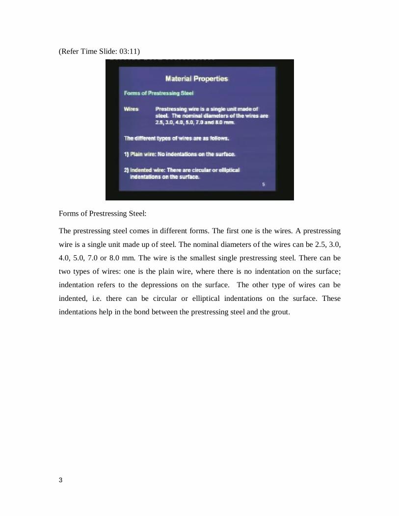
Forms of Prestressing Steel:
The prestressing steel comes in different forms. The first one is the wires. A prestressing
wire is a single unit made up of steel. The nominal diameters of the wires can be 2.5, 3.0,
4.0, 5.0, 7.0 or 8.0 mm. The wire is the smallest single prestressing steel. There can be
two types of wires: one is the plain wire, where there is no indentation on the surface;
indentation refers to the depressions on the surface. The other type of wires can be
indented, i.e. there can be circular or elliptical indentations on the surface. These
indentations help in the bond between the prestressing steel and the grout.
4
(Refer Time Slide: 04:12)
The next form of the prestressing steel is the strands. Here, a few wires are spun together
in a helical form to form a prestressing strand. There can be different types of strands.
The first one is a two-wire strand: here, two wires are spun together to form a helix after
the spinning process. The second type is a three-wire strand, where the strand consists of
three wires spun together. The third wire is a seven-wire strand, where the central wire is
slightly larger than the other six wires, and these six wires are spun around the central
wire in this type of strand.
(Refer Time Slide: 05:09)
5
We can also have the prestressing steel in the form of a tendon. A group of strands or
wires are wound to form a prestressing tendon. In the sketch of the cross-section of a
tendon, we see that several strands have been inserted within a duct, and the duct has
been filled up with grout. This whole assembly or this whole unit is called a tendon.
(Refer Time Slide: 05:45)
A cable is a group of tendons. There can be different groups of tendons to form a cable.
Finally, we come to the bars. A tendon can be made up of a single steel bar where the
diameter of a bar is much larger than that of a wire. The bars are available in the sizes of
10, 12, 16, 20, 22, 25, 28 and 32 mm.
6
(Refer Time Slide: 06:26)
In these figures, we can understand the difference. In the top left, we have a 7-wire strand
which can itself be a tendon. The bottom left is a single bar tendon, where it is just one
unit which forms the tendon. On the bottom right is a multi-wire tendon, where several
wires form the tendon. At the top right, we can see how the tendons are attached in a
post-tensioned member through the help of the anchorage system.
Next, we are moving on to the types of the prestressing steel.
(Refer Time Slide: 07:15)
7
The prestressing steel is treated to achieve the desired property. If there is no other
special treatment then the steel is called as-drawn or untreated steel. But the following are
some special treatments which enhances the properties of the prestressing steel. The first
treatment process is cold working or cold drawing. This process is done by rolling the
bars through a series of dyes. It re-aligns the crystals and increases the strength. That is,
the cold working of a bar is done to increase the strength of the wire which was earlier
having less strength.
(Refer Time Slide: 08:11)
The second treatment process is stress relieving. In this process, the strands are heated to
about 350°C, and then they are cooled slowly. This enhances the stress-strain curve of the
steel, and we shall see this enhancement in a later slide. The third type of treatment is the
strain tampering for low relaxation. In this process, the heating of the strand to about
350°C is done under tension. The resultant stress-strain curve is better, and also the
relaxation observed in this type of steel is lower than the steel which is untreated.
8
(Refer Time Slide: 09:12)
IS: 1343 specifies the material properties of the prestressing steel in Section 4.5. The
following types of steel are allowed. The first type is the plain cold drawn stress relieved
wire conforming to IS: 1785, Part 1. The second is the plain as-drawn wire without any
treatment, conforming to IS: 1785, Part 2. The third is the indented cold drawn wire
conforming to IS: 6003. The fourth is the high tensile steel bar conforming to IS: 2090.
The fifth is the uncoated stress relieved strand conforming to IS: 6006.
All these codes specify the properties of the different types of strands. They also specify
the testing procedure, the sampling procedure and the nomenclature used in the different
types of steel. We are not going into the details of these individual codes, but we shall
refer to the main properties from these codes.
9
(Refer Time Slide: 10:49)
Properties of prestressing steel:
As I mentioned before, that the prestressing steel is different from a conventional non-
prestressed enforcement by several factors. The first one is that the prestressing steel has
to be of high strength. Unless, we have high strength, the initial prestressing strain will
not be large and in that case, there will be substantial loss over time due to the creep and
shrinkage of concrete. Hence, the high strength is a primary requirement of the
prestressing steel.
The second is adequate ductility; in case of vibrating loads, this property becomes
essential. The third is bendability, required at harping points and at ends. The prestressing
steel needs to be bent around the harping points or the hold-on points, and also they are
bent close to the ends because, they change in direction at the anchorage blocks. Hence,
bendability is a requirement for the prestressing tendons.
Fourth is high bond, which is required for pre-tensioned members. In our lecture on pre-
tensioned member, I had mentioned that the transfer of stress from the prestressing steel
to the concrete takes through bond. Hence, the bond is a very important requirement for
the tendons used in pre-tensioned members. In post-tensioned members also, if there is
good bond between the prestressing steel and the grout, then the stress transfer is better
along the length.
10
The fifth important property is low relaxation to reduce loss. We shall cover the concept
of relaxation later in this lecture. It is desired that the prestressing steel should have low
relaxation. Hence, sometimes the steel is heated under tension to have this desirable
property.
Finally, the steel should have minimum corrosion. Although there is an alkaline
environment around the steel, it is always preferred to have steel which is less susceptible
to corrosion.
(Refer Time Slide: 13:24)
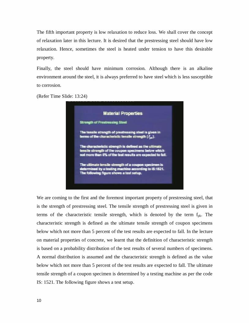
We are coming to the first and the foremost important property of prestressing steel, that
is the strength of prestressing steel. The tensile strength of prestressing steel is given in
terms of the characteristic tensile strength, which is denoted by the term fpk. The
characteristic strength is defined as the ultimate tensile strength of coupon specimens
below which not more than 5 percent of the test results are expected to fall. In the lecture
on material properties of concrete, we learnt that the definition of characteristic strength
is based on a probability distribution of the test results of several numbers of specimens.
A normal distribution is assumed and the characteristic strength is defined as the value
below which not more than 5 percent of the test results are expected to fall. The ultimate
tensile strength of a coupon specimen is determined by a testing machine as per the code
IS: 1521. The following figure shows a test setup.
11
(Refer Time Slide: 14:42)
In this figure, a coupon specimen has been gripped at the two ends. This gripping has
been possible by the wedge action at the top and at the bottom. The testing machine
applies the load on the wedges, which is then transferred to the coupon specimen. The
elongation of the coupon specimen is measured by the extensometer. When we plot the
load versus extension, from there we can get the stress versus strain curve of the
prestressing strand. The strength is calculated from the failure load, at which the first wire
in the strand snaps. The deformation can also be measured by linear variable differential
transducers or in short LVDTs.
12
(Refer Time Slide: 15:55)
After the testing of the specimen, we can see how the specimen has ruptured. The
individual wires in the strands have come separated, and this is the failure state of the
coupon specimen.
(Refer Time Slide: 16:17)
The IS codes for the individual types of wires and strands specifies some minimum
tensile strength for each type of wire. First, in IS: 1785 Part 1 for the cold drawn stress
relieved wires, we see that for wires of diameter 2.5 mm, the minimum tensile strength is
2010 N/mm2. For 3 mm diameter wires, it is 1865 N/mm2; like that for wires of 8 mm
13
diameter, the strength is 1375 N/mm2
. All these values are much higher than those for the
conventional steel that is used in reinforced concrete. In reinforced concrete, the tensile
yield stress is around 250 or 415 or 500 N/mm2. Compared to that, we can observe that
the tensile strength in the prestressing wires is much higher. The proof stress which we
shall define later, should not be less than 85 percent of the specified tensile strength.
(Refer Time Slide: 17:49)
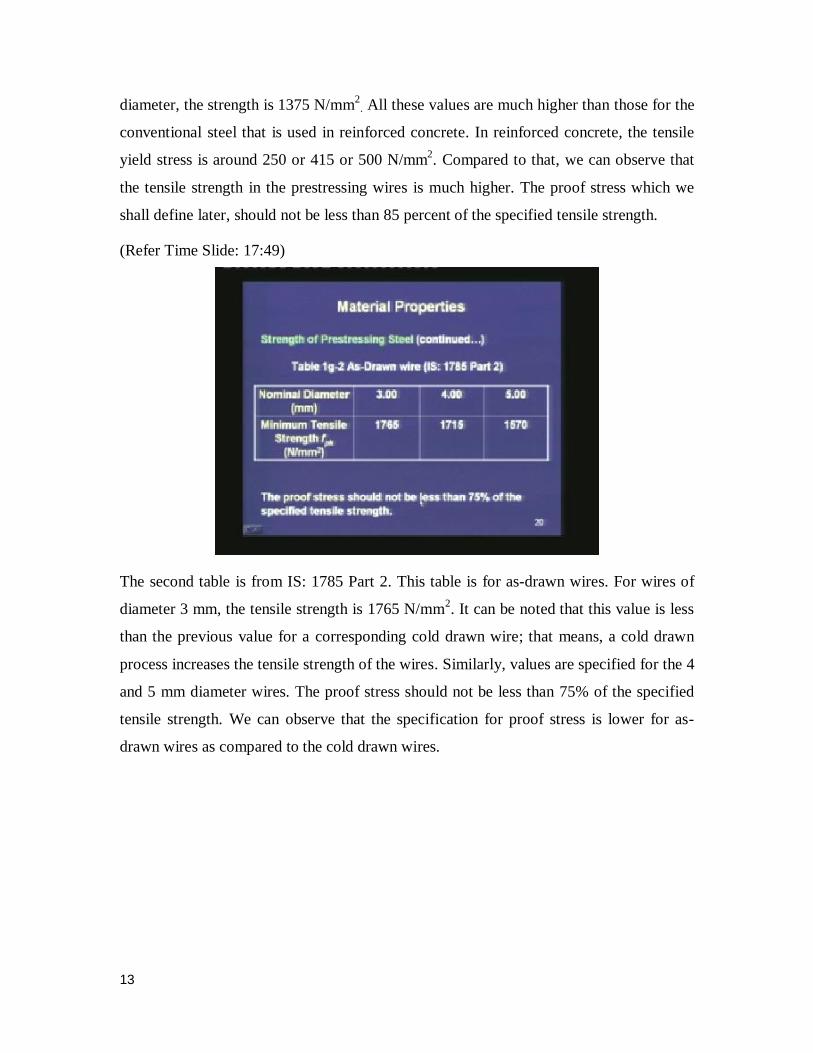
The second table is from IS: 1785 Part 2. This table is for as-drawn wires. For wires of
diameter 3 mm, the tensile strength is 1765 N/mm2. It can be noted that this value is less
than the previous value for a corresponding cold drawn wire; that means, a cold drawn
process increases the tensile strength of the wires. Similarly, values are specified for the 4
and 5 mm diameter wires. The proof stress should not be less than 75% of the specified
tensile strength. We can observe that the specification for proof stress is lower for as-
drawn wires as compared to the cold drawn wires.
14
(Refer Time Slide: 18:51)
The third table is for indented wires. According to IS: 6003, the tensile strength for a 3
mm diameter wire is 1865 N/mm2. Similar values are given for wires of diameters 4 and
5 mm. The proof stress should not be less than 85% of the specified tensile strength.
These values are similar to the cold drawn wires that we have seen in the first table.
(Refer Time Slide: 19:30)
For high tensile steel bars as per code IS: 2090, the minimum tensile strength is 980
N/mm2. We can observe that this value is much lower than the individual wires, which
are shown in the previous three tables. If we use a steel bar as a prestressing tendon, its
15
tensile strength is much less. But the benefit we get is that the anchorage becomes
simpler, where we have to deal with one bar instead of a group of wires or strands. The
proof stress for a bar should not be less than 80 percent of the specified tensile strength.
(Refer Time Slide: 20:21)
Next, we move on to the stiffness of prestressing steel. The stiffness of prestressing steel
is given by the initial modulus of elasticity. The modulus of elasticity depends on the type
of application like wires or strands or bars. Remember that in strands, there is not just a
single wire; it is a cluster of wires which is spun together. When we are testing this
strand, the modulus can be different from the modulus of the individual wires.
16
(Refer Time Slide: 21:12)
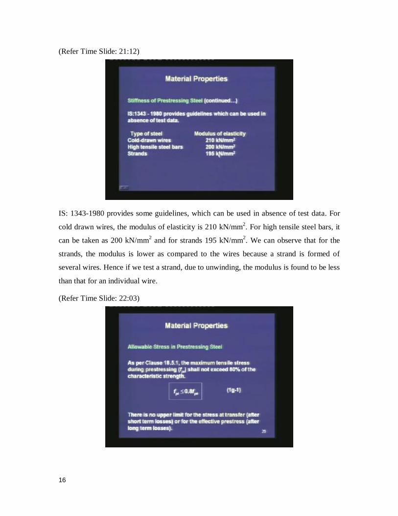
IS: 1343-1980 provides some guidelines, which can be used in absence of test data. For
cold drawn wires, the modulus of elasticity is 210 kN/mm2. For high tensile steel bars, it
can be taken as 200 kN/mm2 and for strands 195 kN/mm
2. We can observe that for the
strands, the modulus is lower as compared to the wires because a strand is formed of
several wires. Hence if we test a strand, due to unwinding, the modulus is found to be less
than that for an individual wire.
(Refer Time Slide: 22:03)
17
Based on the strength of the steel, allowable stresses have been specified in the code,
which should be maintained during the prestressing process. As per Clause 18.5.1, the
maximum tensile stress during prestressing which we are denoting as fpi, shall not exceed
80% of the characteristic strength. During the prestressing process, we have to make sure
that the tensile stress that we are applying on the tendons is limited within 80% of the
characteristic tensile strength. I had told earlier, that the prestressing process is a difficult
process, and we have to take adequate safety measures during the prestressing operation.
The limit is a safety measure, so that the wire does not snap during the prestressing
process. The code IS 1343 does not specify any upper limit for the stress at transfer
which is after the short-term losses, or for the effective prestress which is after the long-
term losses. But in some international codes, there are specifications for these two
stresses.
(Refer Time Slide: 23:37)
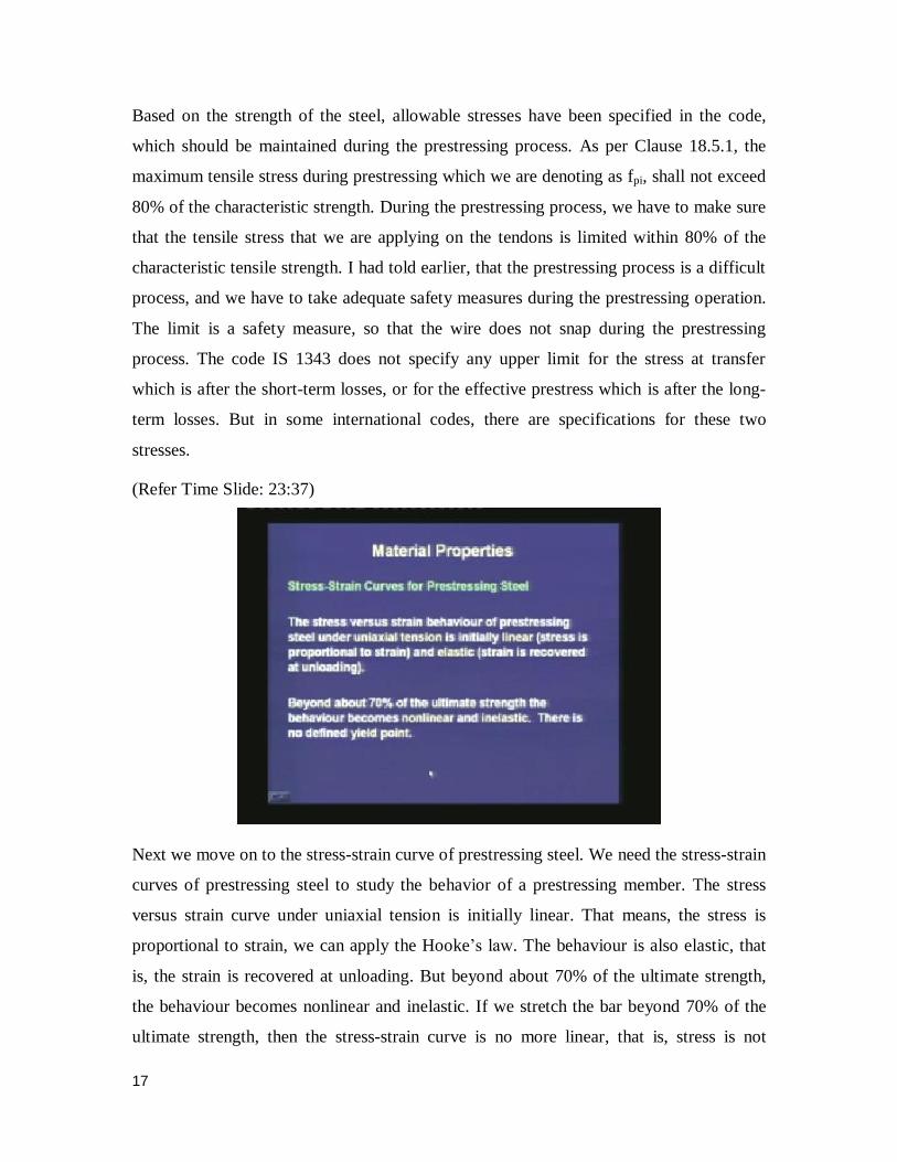
Next we move on to the stress-strain curve of prestressing steel. We need the stress-strain
curves of prestressing steel to study the behavior of a prestressing member. The stress
versus strain curve under uniaxial tension is initially linear. That means, the stress is
proportional to strain, we can apply the Hooke’s law. The behaviour is also elastic, that
is, the strain is recovered at unloading. But beyond about 70% of the ultimate strength,
the behaviour becomes nonlinear and inelastic. If we stretch the bar beyond 70% of the
ultimate strength, then the stress-strain curve is no more linear, that is, stress is not
18
proportional to strain any more. Also, we see some elastic or plastic deformation in the
steel. For prestressing steel, unlike conventional mild steel reinforcement, there is no
specific yield point. That means, we do not have any plateau in the stress-strain curve of
the prestressing steel. Then how do we define the yield point for our design purpose?
(Refer Time Slide: 25:07)
The yield point is defined in terms of the proof stress or a specified yield strain. IS: 1343
recommends the yield point at 0.2% proof stress. Thus, the 0.2% proof stress is defined
as the stress corresponding to an inelastic strain of 0.002. From this graph, we can
understand that initially the stress versus strain is linear, and then it becomes nonlinear
with the increase in stress.
The proof stress is that particular value of the stress which corresponds to a plastic
deformation of 0.002. In order to get the proof stress, we draw a line which is parallel to
the initial part of the curve; wherever this line intercepts the stress-strain curve, we pick
up that point, and the stress corresponding to that point is the proof stress. The purpose of
drawing a line parallel to the initial slope is that we are considering a point which is
having a plastic deformation of 0.002. In some other international codes, the yield point
is defined corresponding to a specified yield strain.
19
(Refer Time Slide: 26:44)
The stress-strain curve for different types of prestressing steel are given in Figure 5 of IS:
1343. In case, if we need the stress corresponding to a strain in our calculations we can
use these curves.
(Refer Time Slide: 27:08)
On the left side, the curve is for stress relieved wires, strands and bars. Here, the curve is
specified in terms of stresses corresponding to different amounts of plastic strain. For the
particular curve on the left, the value of the stress for a plastic strain of 0.002 is 90% of
the characteristic strength. The stress corresponding to a plastic strain of 0.005 is 95% of
20
the characteristic strength. On the right hand side, the curve is for an as-drawn wire.
Here, we can see that the stress corresponding to a plastic strain of 0.002 is lower and it is
given as 85% of the characteristic strength, whereas the plastic strain of 0.005 has a stress
which is almost same as that of the other curve. Thus, the main difference between the as-
drawn and the stress relieved wires is the variation of the stress-strain curve near the
yielding region.
(Refer Time Slide: 28:30)
Let us now try to understand the effect of the different treatment processes that we have
learnt earlier. In this figure, we see that the main variation comes in the particular region
where the bar starts yielding. If we have an as-drawn wire or an untreated wire, then the
variation from the elastic to the plastic region is quite gradual. If we treat this wire to a
stress relieved wire, then we see that this variation is relatively sharper. At the transition,
for a given strain, the stress relieved wires have higher stress compared to the as-drawn
wires. Finally, if we do a low relaxation treatment process then we have a further sharper
peak. Here also we find that for a given strain, the stress is higher as compared to those in
as-drawn and stress relieved wires. After the treatment process, we gain in a higher
elastic behavior, and then the yielding occurs relatively sharply. By this, we achieve a
better behaviour of the stress-strain curve for low relaxation or stress relieved wires, as
compared to as-drawn wires.
21
(Refer Time Slide: 30:12)
From the characteristic curve, we can define the design stress-strain curve. The design
stress-strain curve is calculated by dividing the stress beyond 0.8 fpk by a material safety
factor of γm = 1.15. If we compare the design stress-strain curve of concrete with respect
to its characteristic curve, vis-a-vis the design curve of steel with respect to the
corresponding characteristic curve, we can see that the material safety factor in steel is
applied only after a certain amount of stress. The reason is that, it has been observed that
the variation of the modulus of the steel does not change much for the different grades of
steel. Hence, any variability in the strength is not reflected in the modulus of the steel.
That is why the material safety factor is incorporated only in the strength, and it has not
been incorporated in the initial modulus.
For concrete, the variation of strength also shows a variation in the initial modulus and
hence, the partial safety factor is used throughout the stress-strain curve. A curve of lower
strength will also have a lower elastic modulus. Another difference is that the value of the
material safety factor for concrete is 1.5, because the variability is high; whereas for the
prestressing steel the value of the material safety factor is 1.15 which is lower than that
for concrete.
22
(Refer Time Slide: 32:24)
We are moving on to another important property of steel, i.e. relaxation of steel. The
relaxation of steel is defined as the decrease in stress with time under constant strain. Due
to the relaxation of steel, the prestress in the tendon is reduced with time. Hence, the
study of relaxation is important in prestressed concrete to calculate the loss in prestress.
Earlier in the study of the material properties of concrete, we had studied creep and
shrinkage. We understood that these phenomenons are very important to be studied for
prestressed concrete, because they lead to the loss of prestress over time. Similarly, the
relaxation is also an important property which needs to be studied because it also has the
same effect of the reduction of prestress over time. The relaxation of steel depends on the
type of steel, the amount of initial prestress, and the temperature to which the steel is
subjected.
23
(Refer Time Slide: 33:42)
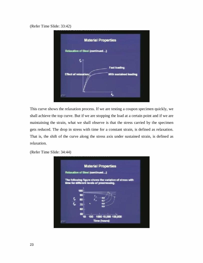
This curve shows the relaxation process. If we are testing a coupon specimen quickly, we
shall achieve the top curve. But if we are stopping the load at a certain point and if we are
maintaining the strain, what we shall observe is that the stress carried by the specimen
gets reduced. The drop in stress with time for a constant strain, is defined as relaxation.
That is, the shift of the curve along the stress axis under sustained strain, is defined as
relaxation.
(Refer Time Slide: 34:44)
24
The above figure shows the variation of stress with time, for different levels of initial
stressing. If the initial stressing is about 60% of the characteristic strength, then the drop
of the prestress due to relaxation is much lower. But if we increase the initial stressing to
say 70%, 80%, or 90% of the characteristic strength, then we see that the drop in
prestress with time gets substantial. This is another reason why the code limits the value
of the initial prestress to 80% of the characteristic strength, so that the relaxation loss is
relatively limited. Note that, here the time axis is a logarithmic axis. Most of the
relaxation tests are done for a period of 1000 hours, or if it is not possible to do for 1000
hours, then the tests are done for a period of 100 hours.
(Refer Time Slide: 36:05)
It can be observed that there is significant relaxation loss over a period, when the applied
stress is more than 70% of the characteristic tensile strength. We have to be aware that if
we are stretching the tendons beyond 70% of the characteristic strength, we shall see
significant relaxation loss. Hence, we have to include that in our calculation of the
effective prestress after several years.
25
(Refer Time Slide: 36:43)
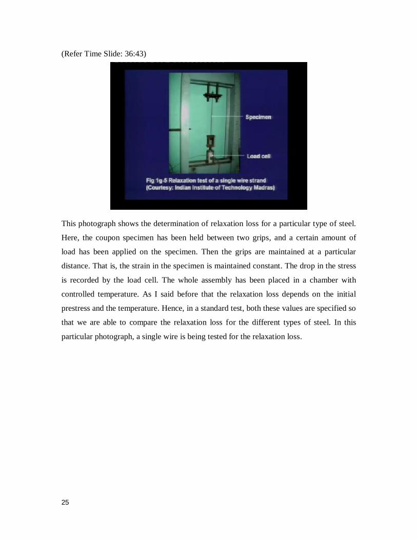
This photograph shows the determination of relaxation loss for a particular type of steel.
Here, the coupon specimen has been held between two grips, and a certain amount of
load has been applied on the specimen. Then the grips are maintained at a particular
distance. That is, the strain in the specimen is maintained constant. The drop in the stress
is recorded by the load cell. The whole assembly has been placed in a chamber with
controlled temperature. As I said before that the relaxation loss depends on the initial
prestress and the temperature. Hence, in a standard test, both these values are specified so
that we are able to compare the relaxation loss for the different types of steel. In this
particular photograph, a single wire is being tested for the relaxation loss.
26
(Refer Time Slide: 38:00)
In this sketch, it is a similar type of set up where a strand is being tested for the relaxation
loss.
(Refer Time Slide: 38:14)
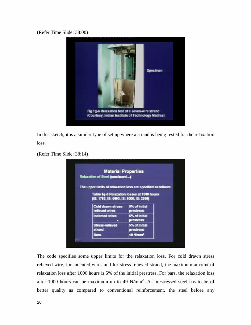
The code specifies some upper limits for the relaxation loss. For cold drawn stress
relieved wire, for indented wires and for stress relieved strand, the maximum amount of
relaxation loss after 1000 hours is 5% of the initial prestress. For bars, the relaxation loss
after 1000 hours can be maximum up to 49 N/mm2. As prestressed steel has to be of
better quality as compared to conventional reinforcement, the steel before any
27
construction should be subjected to the tests specified in the code, and the designer
should check those test results before approving the construction of the structure. The
material testing is a very important aspect of precast, prestressed concrete construction.
(Refer Time Slide: 39:39)
When we are doing some design calculations, if we do not have any test data, then the
code allows us to use the above table to calculate the relaxation loss. Depending upon the
initial stress, we can calculate the relaxation loss and these values are as follows. If the
initial stress is about 50% of the characteristic strength, then we do not have to consider
any relaxation loss. If the initial stress is 60%, the relaxation loss is 35 N/mm2
. Similarly,
if the initial stresses are 70% or 80% of the characteristic strength, then the relaxation
losses are 70 and 90 N/mm2, respectively. We can observe that with the increase in the
initial stress, the relaxation losses are also increasing.
28
(Refer Time Slide: 40:33)
The next property that we shall study is the fatigue. Fatigue is a concern under repeated
load or even reverse load. Under repeated dynamic loads, the strength of a member may
reduce with the number of cycles of applied load. The reduction in strength is referred to
as fatigue. Fatigue is a concern in structures like bridges or any other structural element
which is subjected to vibration. In prestressed applications, the fatigue is negligible in
members that do not crack under service loads. But if a member cracks, fatigue may be a
concern due to high stress in the steel at the locations of the cracks. Earlier, we had said
that we can design the prestressed members as one of the three types. For Type 1, no
tensile stress is allowed in the prestressed member. For Type 2, tensile stress is allowed,
but no cracking is allowed. For Type 3, tensile stress and cracking are allowed, but the
cracking is limited only to a certain extent, i.e. the crack width is limited. Hence, the
fatigue becomes a concern for Type 3 members. If we are designing a structure as Type 1
and Type 2 for the service loads, then we may not check for the fatigue.
29
(Refer Time Slide: 42:27)
For fatigue testing, the specimens are tested under 2 million cycles of the load. For steel,
the fatigue tests are conducted to develop the stress range versus number of cycles for
failure (S-N) diagram. The S-N curve is an important characteristic behaviour to study
the effect of fatigue. The S-N curve is a plot of the range of stress fluctuation versus the
number of cycles which leads to failure. Under a limiting value of the stress range, the
specimen can withstand infinite number of cycles, and this limit is known as the
endurance limit. Let me explain the S-N diagram by a sketch.
(Refer Time Slide: 43:35)
30
The S-N curve plots the stress range corresponding to the number of cycles for failure.
What is observed is, as the number of cycles increases, the stress range reduces. But
beyond a certain value, say a value of 2 million cycles, the stress range does not reduce.
This value of stress range is called the endurance limit. Thus, if a structure is subjected to
repeated loading and if we design the structure in such a way that the stress range is
within the endurance limit, then we do not have a problem of fatigue. If the stress range
exceeds the endurance limit, then we will have a problem of fatigue when the
corresponding number of cycles is crossed.
(Refer Time Slide: 45:03)
Usually the prestressed member is designed in such a way that the stress in the steel due
to the service load remains under the endurance limit. That means the members are
designed such that the stresses will not lead to a fatigue problem.
31
(Refer Time Slide: 45:32)
This photograph shows a fatigue testing of prestressing steel and an anchorage block.
Here, the pulsating load is applied by two jacks. There is a beam at the bottom, and there
is a reaction beam at the top. As the pistons are moving down, the bottom beam is
moving down, and it is applying tension to the steel. This load is being varied over
several cycles to study the fatigue behavior of the prestressing steel and the anchorage
block. As I said, usually these tests are done for 2 million cycles to check that the
prestressing steel and the anchorage block are satisfactory to sustain the repeated loading.
Next, we move on to the durability of prestressing steel.
32
(Refer Time Slide: 46:40)
The prestressing steel is susceptible to stress corrosion and hydrogen embrittlement in
aggressive environments. Hence, the prestressing steel needs to be adequately protected.
Compared to conventional reinforcement, prestressing steel is subjected to much higher
stress. This leads to some durability problems, which are termed as stress corrosion and
hydrogen embrittlement. These two types of durability problems are more possible in
aggressive environments. Hence, we need to check any corrosion problem of the
prestressing steel. As I mentioned earlier, the amount of prestressing steel is usually
much lower than the amount of conventional reinforcement. Hence, any corrosion of the
prestressing steel is more dangerous as compared to the reinforcement steel. The
reduction of diameter of a prestressing tendon will lead to more problem, because the
proportional reduction in area is higher as compared to the same amount of reduction for
reinforcement steel.
33
(Refer Time Slide: 48:13)
For bonded tendons, the alkaline environment of the grout provides adequate protection.
In pre-tensioned members, or in post-tensioned members where the grouting has been
done properly, the grout itself provides an alkaline environment around the prestressing
steel, which protects the steel from corrosion. But, if we are using unbonded prestressing
tendons in post-tensioned members, then we have to be careful about the corrosion
problem. Several corrosion protection measures are taken. They can be one of the
following.
We can coat the prestressing tendons with epoxy; but this type of tendons has reduced
bond. Hence, if we are using epoxy coated steel for pre-tensioned members, then we have
to be careful that the stress transfer over a certain length will be reduced. The second
protection measure is by wrapping the prestressing steel by some mastic tapes. These
mastic tapes are grease impregnated tapes which protect the steel from any corrosion
coming from acidic environment. We can use galvanised bars as prestressing tendons, but
the cost of galvanised bars is substantially higher than conventional prestressing steel.
Else, we can also use some tubes to encase the unbonded tendons within the duct itself.
Thus, when the ducts are not grouted, prestressing steel is susceptible to corrosion. To
avoid corrosion, we are either using some epoxy coating, or we are covering it by some
mastic wrap, or we are encasing them in tubes, or we may use galvanized bars to check
the corrosion.
34
(Refer Time Slide: 50:29)
There are several other provisions in IS: 1343 regarding the handling of prestressing
steel. These provisions are not being reproduced here because they are self-explanatory,
and it is expected that you get familiar with those provisions. The assembly of
prestressing and reinforced steel is explained in Section 11. Since the prestressing
operation is a difficult operation, it needs skilled personnel to perform this operation and
hence, the code specifies some provisions for the prestressing process. The specifications
for prestressing are covered under Section 12 of the code.
(Refer Time Slide: 51:36)
35
Today, we covered the material properties of prestressing steel. As I said, the prestressed
concrete became successful only after the invention of high strength steel. Because, if we
use conventional steel, then the loss of prestress will be substantially high as compared to
the initial prestress that can be allowed. Hence, the effective prestress will be almost
negligible. If we are having high strength steel, then the initial strain and the initial
prestress are substantially high. Then, even after the losses, the effective prestress will be
substantial. Hence, the prestressed concrete member will be successful to carry the
service loads.
First, we discussed the different forms of prestressing steel. The prestressing steel can be
in the form of a wire, which is an individual unit. The different wire diameters are
specified in the code. The wires can be plain wires or indented wires. The indented wires
have some depressions on the surface.
Next, we moved on to the strands. The strands are made up of several wires spun together
in a helical form. It can be a two-wire strand, or three-wire strand, or a seven-wire strand.
Several strands can be grouped together to form a tendon. The strands are placed in a
duct and the duct is grouted in a post-tensioned member to form a tendon. Several
tendons can be grouped together to form a prestressing cable. Sometimes the tendons are
made up of individual bars, and these individual bars are of much larger diameter. The
bars are used because it is easy to anchor them in the concrete.
Next, we moved on to the different types of prestressing steel. We learnt that, if the
prestressing steel is untreated or as-drawn, then the stress-strain behavior may not be
satisfactory. Hence, some treatment processes are undertaken to enhance the strength or
the stress-strain behaviour. In cold working, the strength is increased. In the stress
relieving process or in the low relaxation steel, the stress-strain behaviour is enhanced
where the curve at the yield region is higher than the curve corresponding to an as-drawn
wire.
Next, we moved on to the properties of prestressing steel. The first property that we
studied was the strength, because that is the most important property of the prestressing
steel. Thus, minimum strength requirements for the different types of prestressing steel
are given in the different codes. For the wires, we have found that the characteristic
36
strengths are much higher compared to the characteristic strengths of conventional
reinforcing bars. For a single bar prestressing tendon, the tensile strength is lower than
that of the wires, but still that is much higher compared to that of conventional
reinforcement.
The tensile strength can be obtained by tests performed in testing machines, wherein the
coupon specimen is held between two grips and the deformation is measured by
extensometers or LVDTs. The tensile strength is calculated from the load at failure. We
also learnt about the stiffness of prestressing steel which is measured by the elastic
modulus. We have seen that the elastic modulus of strand is lower than that of the
individual wires, because the wires in the strand are spun together. The code gives us
some guidelines for the elastic modulus, which can be used in absence of test data.
We moved on to the stress-strain curve of prestressing steel. We had found that unlike
conventional reinforcement of mild steel, the prestressing steel does not have any yield
plateau. The code gives us some characteristic curves, from which we can calculate the
stress corresponding to a strain. We learnt the definition of proof stress, i.e. a 0.2 percent
proof stress is the stress corresponding to a plastic deformation of 0.002. The code
specified minimum proof stress for the different types of steel.
Next, we moved on to an important property of steel, which is the relaxation. The study
of relaxation is important because it helps us to calculate the loss of prestress over time.
The relaxation of steel depends on the initial prestress. It depends on the type of steel, and
also on the temperature. What we have found is that if the initial prestress is substantially
high, say beyond 70% of the characteristic strength, then the relaxation loss can be
substantial. The code limits the initial prestress to 80% of the characteristic strength.
First, for the safety reason and second that the relaxation loss should be limited. The code
specifies the maximum amounts of relaxation loss for different types of steel. In our
design calculations, if we need the relaxation loss then the code gives us some lump sum
values, which are independent of time. If we need more detailed calculations, then we
have to look into special literature.
We also looked into the durability and fatigue of the prestressing steel. Both of these can
be important under specific situations. Hence, depending on the case, we have to
37
investigate them in detail. In our next class, we shall move on to the calculation of losses