Prevision of settlement-induced cracking in historical building masonry façades
J.G. Rots Delft University ofTechnology, Delft, The Netherlands
S. Invernizzi Politecnico di Torino, Torino, /taly; visiting researchfellow Delft University ofTechnology
ABSTRACT: In the present paper lhe case study of an historical masonry building is presented in order to assess the settlement-induced cracking due to recent underground tunneling. A comprehensive numerical analysis is carried out in the framework of classical nonlinear smeared crack models. The building structure is analyzed by modeling the most important 20 sections, respectively parallel and orthogonal to the tunnel trace. The results obtained from the numerical simulation allow assessing the criticai angular distortion after which some mitigation countermeasures are necessary to avoid the faça de cracking. This value can be compared with the expected one, as well as with results provided by real-time monitoring during the tunnel excavation. A future development of the study could be directed to assess the effectiveness of possible structural strengthening.
INTROOUCTlON
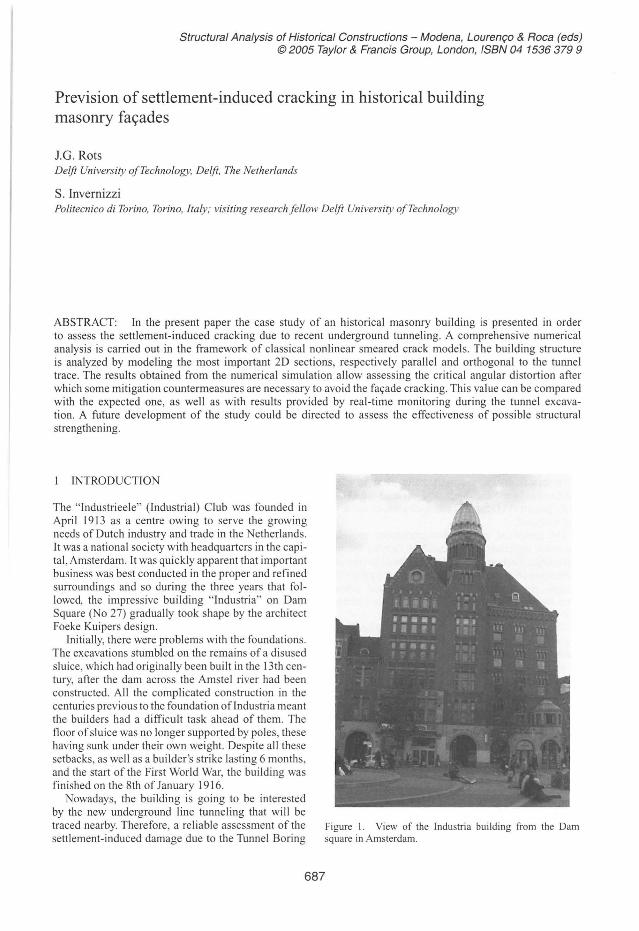
The "Industrieele" (Industrial) Club was founded in April 1913 as a centre owing to serve the growing needs of Outch industry and trade in the Netherlands. It was a national society with headquarters in the capital , Amsterdam. It was quickly apparent that important business was best conducted in the proper and refined surroundings and so during the three years that followed, the impressive building "Industria" on Oam Square (No 27) gradually took shape by the architect Foeke Kuipers designo
Initially, there were problems with the foundations. The excavations stumbled on the remains of a disused sluice, which had originally been built in the 13th century, after the dam across the Amstel river had been constructed. Ali the complicated construction in the centuries previous to the foundation ofIndustria meant the builders had a difficult task ahead of them. The floor of sluice was no longer supported by poles, these having sunk under their own weighl. Oespite ali these setbacks, as well as a builder's strike lasting 6 months, and the start of the First World War, the building was finished on the 8th of January 1916.
Nowadays, the building is going to be interested by the new underground line tunneling that will be traced nearby. Therefore, a reliable assessment of the settlement-induced damage due to the Tunnel Boring
Figure I. View of lhe Industria building from the Dam square in Amsterdam.
687
Machine (TBM) is necessary in order to design properly the possible countermeasures (e.g. compensation soil grouting or structural strengthening).
A comprehensive numerical analysis is described in the paper, carried out in the framework of classical nonlinear smeared crack models.
The building structure is analyzed by modeling the most important 20 sections, respectively parallel and orthogonal to the tunnel trace. The model includes a representation of the pile foundation, while settlements of the deep soil layer are assigned based on geotechnical evidences.
The results obtained from the numerical simulation allow assessing the criticaI angular distortion after which some mitigation countermeasures are necessary to avoid the faça de cracking. This value can be compared with the expected one, as well as with results provided by real-time monitoring during the tunnel excavation.
A future development ofthe study could be directed to assess the effectiveness of possible structural strengthening.
2 GEOMETRICAL SURVEY
The geometrical survey of the building has been carried out based on both historical drawings and digital photogrammetry of the facades.
Historical drawings provided the main in plane dimensions of the buildings, and justified the choice ofthe principal 20 façades and sections to be modeled and analyzed.
The terrestria l digital photogrammetry provided the exact elevations of the building façades through three steps. First several digital pictures of the façades were taken (Nikon® CoolPix 990). Then, digital tilted images were transformed into orthogonal projections by means of a rectification procedure (Archis® software).
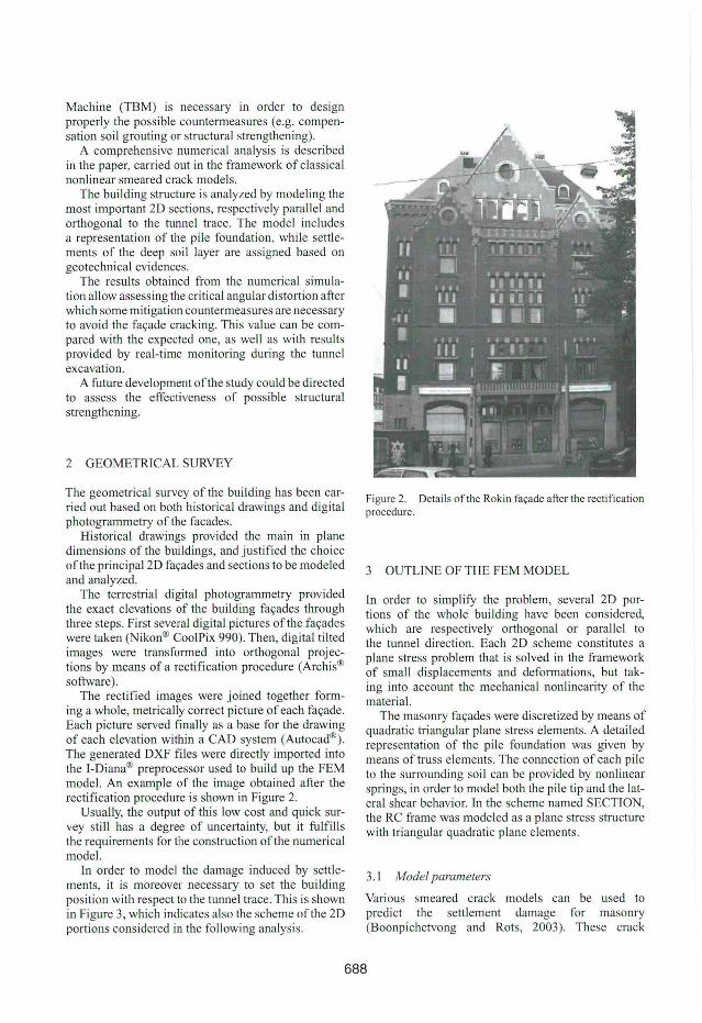
The rectified images were joined together forming a whole, metrically correct picture of each façade. Each picture served finally as a base for the drawll1g of each elevation within a CAO system (Autocad®). The generated OXF files were directly imported into the I-Oiana® preprocessor used to build up the FEM model. An example of the image obtained after the rectification procedure is shown in Figure 2.
Usually, the output of this low cost and quick survey still has a degree of uncertainty, but it fulfills the requirements for the construction ofthe numerical model.
In order to model the damage induced by settlements, it is moreover necessary to set the building position with respect to the tunnel trace. This is shown in Figure 3, which indicates also the scheme ofthe 20 portions considered in the following analysis.
Figure 2. Details ofthe Rokin façade after the rectification procedure.
3 OUTLINE OF THE FEM MOOEL
In order to simplify the problem, several 20 portions of the whole building have been considered, which are respectively orthogonal or parallel to the tunnel direction. Each 20 scheme constitutes a plane stress problem that is solved in the framework of small displacements and deformations, but taking into account the mechanical nonlinearity of the material.
The masonry façades were discretized by means of quadratic triangular plane stress elements. A detailed representation of the pile foundation was given by means of truss elements. The connection of each pile to the surrounding soil can be provided by nonlinear springs, in order to model both the pile tip and the lateral shear behavior. In the scheme named SECTION, the RC frame was modeled as a plane stress structure with triangular quadratic plane elemellts.
3.1 Model parameters
Various smeared crack models can be used to predict the settlement damage for masonry (Boonpichetvong and Rots, 2003). These crack
688
/
!Back façade
Figure 3. Oetails of lhe tunnels under Rokin road, and of the 20 façades and section of the Industria building. Note that most relevant 20 schemes are respectively orthogonal or parallel to the tunnel trace.
models are: (a) decomposed-strain fixed smeared crack, (b) total strain fixed smeared crack, (c) total strain rotating smeared crack and (d) Rankine plasticity crack model. The detailed formulations of these crack models are described in respectively Rots (1998), Feenstra et aI. (1998) and Feenstra (1993). In the present study priority has been given to the total strain fixed smeared crack approach.
The foundation grillage, the walls below the levei of the ground, as well as the RC frame in the SECTION scheme, has been considered made of C30 concrete. In other words, the compressive and tensile behavior are elastic-perfectly plastic. The compressive strengthfc is equal to 30 MPa, while the tensile strength.fc is equal to 2.9 MPa. The elastic behavior of such concrete is characterized by the Young modulus E equal to 34000 MPa and the Poisson 's ratio v =0.15.
The masonry façade has been given a tensile strengthfr equal to 0.3 MPa, with linear post peak softening and fracture energy Gf equal to 50 N/m. The compressive behavior is elastic-perfectly plastic, and the compressive strengthfc equal to 3 MPa. The elastic behavior ofthe masonry is characterized by the Young modulus E equal to 6000 MPa and the Poisson 's ratio v=0.2.
In both cases the shear retention behavior was described by a constant shear retention factor fJ equal to 0.0 I.
3.2 Loadings
First, the dead load of the masonry is activated. The dead load is computed with respect to the façade thickness, which decreases at higher floors, and assuming a density equal to 2400 kglm3 . In addition, a self-weight and live 10ad of 5 kN/m is provided at each floor leveI.
Next, settlement profiles have been applied increasing the magnitude. This approach can be considered a semi-coupled analysis since the green-field settlements trough is applied directly to the foundation pile 's tip leveI.
Based on the analysis of case records (e.g. Maier et aI. 1996), the immediate transverse settlement trough (S v ) at the horizontal distance y from the tunnel center line is well described by an inverted Gaussian distribution curve as:
s =s exp( -i) v max 2i2
' (1 )
where i is the horizontal distance from the tunnel center! ine to the point ofinflection ofthe settlement trough (i = Kzo). K is the trough width parameter for tunnels and is taken as 0.8 in this study. Zo is the depth of the tunnel axis with respect to the pile tip levei, which is 12 m herein. The maximum settlement SITIa. is achieved right above the tunnel centerline, and can be estimated as follows:
v D2 s ~_L __
max &i' (2)
where D is the diameter of the tunnel (D = 7.02 m herein), and VL the so called "volume loss", which depends upon the drilling condition (VL = 0.0081 in our case).
A scheme of the settlement trough with respect to the tunnel front during the drilling phase is shown in Figure 4.
The amount ofhorizontal displacement can be estimated with a similar expression. In the present study horizontal displacements have not been taken into consideration.
Since two tunnels will be constructed close to each other, it is assumed, as commonly done for routine design purposes, that the ground movements that would have occurred for each tunnel acting independently can be superimposed. lt shall be reminded that Mair and Taylor (1997) refer to case histories that shows this assumption can underestimate the movements generated by the construction of subsequent tunnels.
Referring to the Figure 2 scheme, the transverse settlement trough has been applied to the DAM and BACK façades as well as to the SECTION.
On the other hand, the ROKIN façade will be afflicted by the longitudinal settlement trough, which
689
~-x
Figure 4. Scheme of the tunnel advancement and the corresponding settlement trough (Burland et aI. , 2001).
develop in front of the tunnel and moves together the tunnel front as the drilling advances. In the present study the shape ofthe longitudinal settlement trough as been adopted with the same analytical form of eq. (1).
4 NONLINEARANALYSIS RESULTS
In this section, results from the non!inear analysis of the four 2D considered schemes are described singularly. More general considerations about the overall building response have been collected in the following section.
4.1 DAMfaçade
The DAM façade face Dam Square, and is orthogonal to the tunnel traces, therefore the reader should picture the tunnels on the right side in Figures 5- 6.
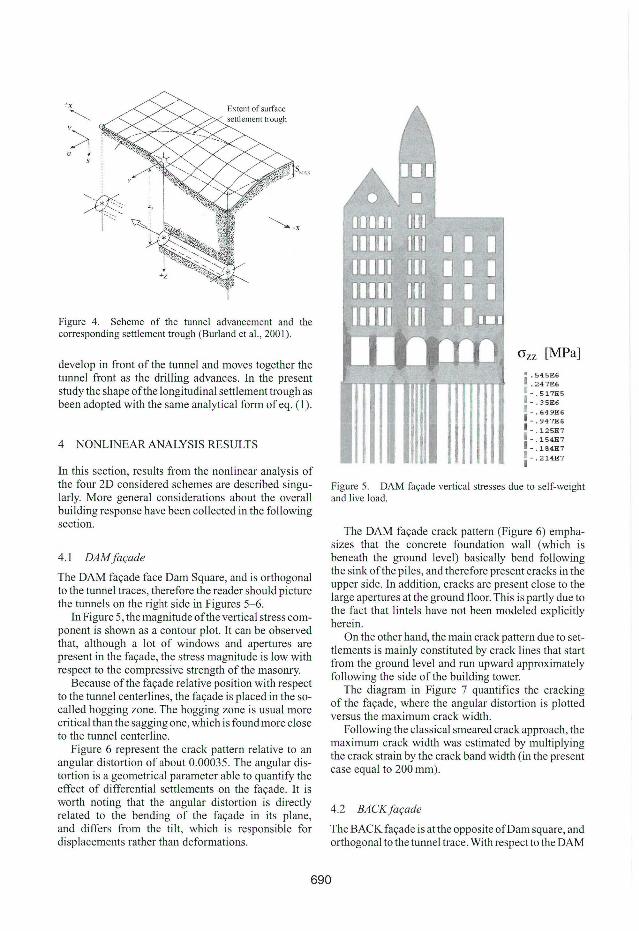
In Figure 5, the magnitude ofthe vertical stress component is shown as a contour plot. It can be observed that, although a lot of windows and apertures are present in the façade, the stress magnitude is low with respect to the compressive strength ofthe masonry.
Because ofthe façade reI ative position with respect to the tunnel centerlines, the façade is placed in the socalled hogging zone. The hogging zone is usual more criticaI than the sagging one, which is found more close to the tunnel centerline.
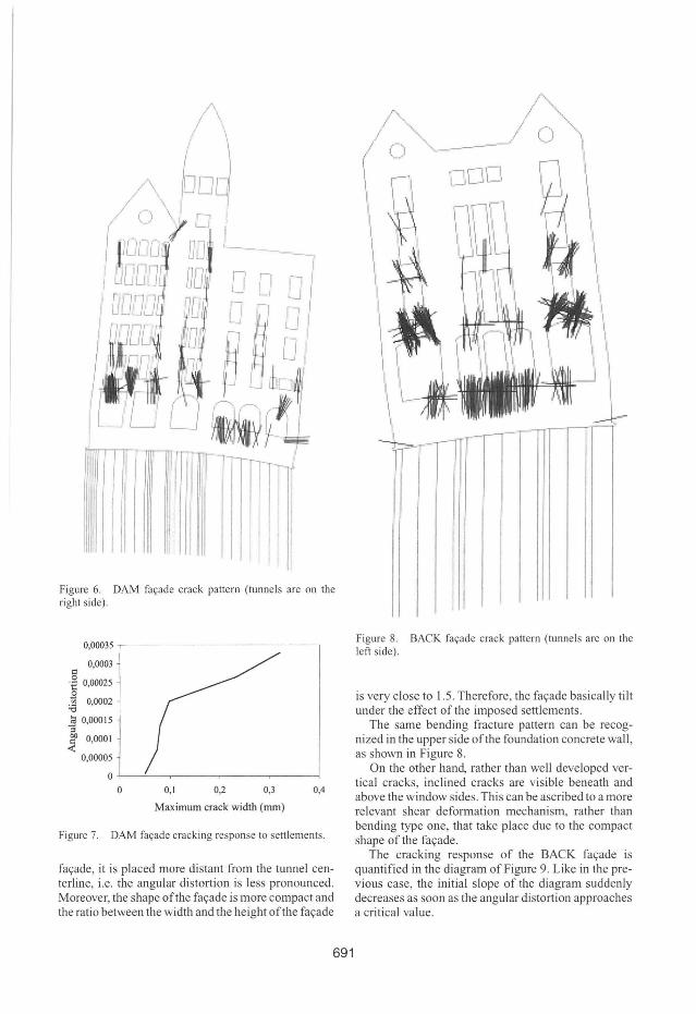
Figure 6 represent the crack pattem relative to an angular distortion of about 0.00035. The angular dlstortion is a geometrical parameter able to quantify the effect of differential settlements on the façade. It is worth noting that the angular distortion is directly related to the bending of the faça de in its plane, and differs from the tilt, which is responsible for displacements rather than deformations.
(}zz [MPa]
i . 545E6 r ~:~~:5 II =: ~~::6
- . 947E6 1- .1 2 5E7 1 - .154E7 1 -.1S4E7
1- 214E7 I .
Figure 5. DAM façade vertical slresses due lo self-weight and live load.
The DAM faça de crack pattem (Figure 6) emphasizes that the concrete foundation wall (which is beneath the ground leveI) basically bend following the sink of the piles, and therefore present cracks in the upper side. In addition, cracks are present close to the large apertures at the ground floor. This is partly due to the fact that lintels have not been modeled explicitly herein.
On the other hand, the main crack pattern due to sett1ements is mainly constituted by crack !ines that start from the ground leveI and mn upward approximately following the side ofthe building tower.
The diagram in Figure 7 quantifies the cracking of the façade, where the angular distortion is plotted versus the maximum crack width.
Following the classical smeared crack approach, the maximum crack width was estimated by multiplying the crack strain by the crack band width (in the present case equal to 200 mm).
4.2 BACKfaçade
The BACK façade is at the opposite ofDam square, and orthogonal to the tunnel trace. With respect to the DAM
690
Figure 6. DAM façade crack pattern (tunnels are on the right side).
Cl
0,00035
0,0003
.€ 0,00025 o .~ 0,0002
"" ~ 0,00015 . '3 .r 0,0001
0,00005
O+-~~-r------r-----~----~
O 0,1 0,2 0,3 0,4
Maximum crack width (mm)
Figure 7. DAM façade cracking response to settlements.
façade, it is placed more distant from the tunnel centerline, i.e. the angular distortion is less pronounced. Moreover, the shape ofthe façade is more compact and the ratio between the width and the height ofthe façade
691
Figure 8. BACK faça de crack pattern (tunnels are on the left side).
is very close to 1.5. Therefore, the façade basically tilt under the effect of the imposed settlements.
The same bending fracture pattem can be recognized in the upper side ofthe foundation concrete wall , as shown in Figure 8.
On the other hand, rather than well developed vertical cracks, inclined cracks are visible beneath and above the window sides. This can be ascribed to a more relevant shear deformation mechanism, rather than bending type one, that take place due to the compact shape of the façade.
The cracking response of the BACK façade is quantified in the diagram ofFigure 9. Like in the previous case, the initial slope of the diagram suddenly decreases as soon as the angular distortion approaches a criticai value.
0,0005
0,00045
g 0,0004
'i: 0,00035
~ 0,0003 :e 0,00025
i o~~~~~~ <t:: 0,0001
0,00005
O+J---.-----.----~----,_--~
o 0,1 0,2 0,3 0,4 0,5
Maximum crack width (mm)
Figure 9. BACK façade cracking response to settlements.
4.3 SECTION model
The SECTION scheme is obtained from a section of the building placed parallel and right beneath the BACK façade. Therefore, the model is composed of an outer masonry wall and an inner RC frame. In the central part, the foundation wall is absent, and the RC frame is placed directly upon the foundation reverse beam.
Being larger than the BACK façade, the SECTION scheme is relatively closer to the tunnel centerline. This results in a more curved settlement prof ile.On the other hand, the SECTION scheme is more flexible than the previous one, and this is an advantage since imposed settlements cause less severe stress in the stmcture.
The crack pattern in the SECTION scheme is shown in Figure 10. The first cracks that nucleate are those in the upper region of the ou ter masonry wall.
When the angular distortion increases, also the lower zones of the outer masonry wall crack. Figure 10 shows a prevalent shear type crack pattern, with cracks that follow a curved path rather than run straight through the façade .
The diagram in Figure 11 quantifies the angular distortion vs. maximum crack width for the SECTION scheme. The behavior does not differ significantly from the previous ones, and is characterized by a basically bilinear response.
4.4 ROKIN façade
The ROKIN façade face the Rokin road, beneath which the tunnels will be drilled.
This is the largesl façade ofthe building, i.e. the one with the lower height over width ratio.
AIso the kind of settlement profile profoundly differs from the previous cases. Due lo the fact that the tunnels mn parallel to the façade, the settlement profile does not increase monotonously. In other words, there are two regime configurations, respectively before the tunnel front travei under the building, and well after, for which the differential settlements are zero.
Figure 10. SECTlON crack pattem (tunnels are on lhe left side).
0,00045 ---------------------~- ..
0,0004
§ 0,00035
.~ 0,0003
~ 0,00025
ti; 0,0002
~ 0,00015
.:i! 0,0001
0,00005
O~----~----_.------r_--~
o 0,1 0,2 0,3 0,4
Maximum crack width (mm)
Figure 11. SECTlON model cracking response lo settlements .
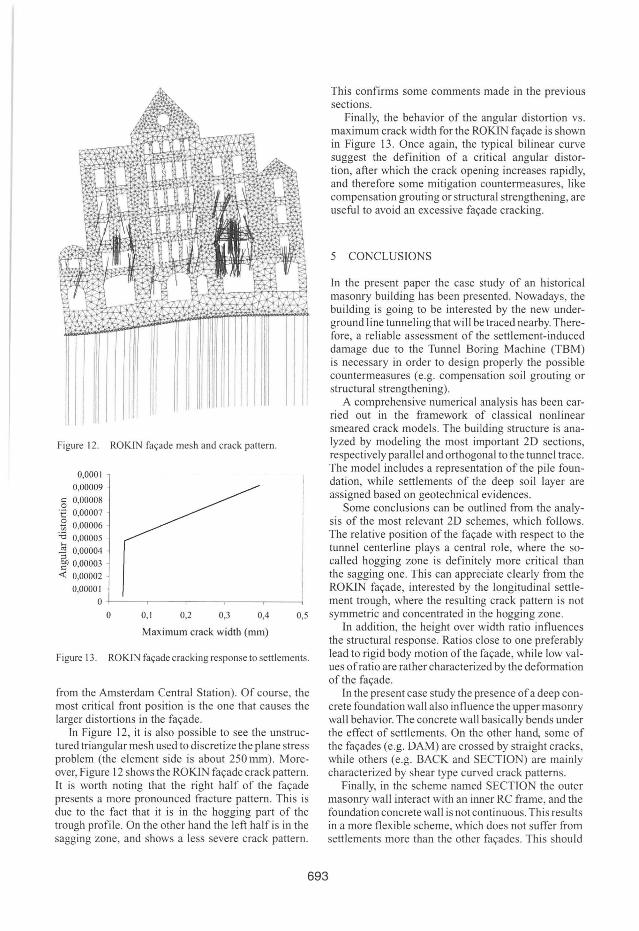
The dangerous differential settlements are experienced by the façade only in the transitory phase. An example is shown in Figure 12, where the tunnel front is coming from the left side ofthe faça de (i.e. coming
692
Figure 12. ROKJN faça de mesh and crack pattem.
0,0001
0,00009
g 0,00008 'i:: 0,00007
â 0,00006 -'Õ 0,00005
~ 0,00004 51 000003 -c '
<C 0,00002
0,00001
O +----.-----r----.-----.---~
O 0,1 0,2 0,3 0,4 0,5
Maximum crack width (mm)
Figure 13. ROKJN façade cracking response to settlements.
from the Amsterdam Central Station). Of course, the most criticai front position is the one that causes the larger distortions in the façade.
In Figure 12, it is also possible to see the unstructured triangular mesh used to discretize the plane stress problem (the element side is about 250 mm). Moreover, Figure 12 shows the ROKfN façade crack pattern. Tt is worth noting that the right half of the façade presents a more pronounced fracture pattem. This is due to the fact that it is in the hogging part of the trough profile. On the other hand the left half is in the sagging zone, and shows a less severe crack pattern.
693
This confirms some comments made in the previous sections.
Finally, the behavior of the angular distortion vs. maximum crack width for the ROKIN façade is shown in Figure l3. Once again, the typical bilinear curve suggest the definition of a critical angular distortion, after which the crack opening increases rapidly, and therefore some mitigation countermeasures, like compensation grouting or structural strengthening, are useful to avoid an excessive façade cracking.
5 CONCLUSIONS
In the present paper the case study of an historical masonry building has been presented. Nowadays, the building is going to be interested by the new underground line tunneling that will be traced nearby. Therefore , a reliable assessment of the settlement-induced damage due to the Tunnel Boring Machine (TBM) is necessary in order to design properly the possible countermeasures (e.g. compensation soil grouting or structural strengthening).
A comprehensive numerical analysis has been carried out in the framework of classical nonlinear smeared crack models. The building structure is anaIyzed by modeling the most important 2D sections, respectively parallel and orthogonal to the tunnel trace. The model includes a representation ofthe pile foundation, while settlements of the deep soil layer are assigned based on geotechnical evidences.
Some conc1usions can be outlined from the analysis of the most relevant 2D schemes, which follows. The relative position ofthe façade with respect to the tunnel centerline plays a central role, where the socalled hogging zone is definitely more criticai than the sagging one. This can appreciate clearly from the ROKIN façade, interested by the longitudinal settlement trough, where the resulting crack pattern is not symmetric and concentrated in the hogging zone.
In addition, the height over width ratio influences the structural response. Ratios close to one preferably lead to rigid body motion ofthe façade , while low values of ratio are rather characterized by the deformation of the façade.
In the present case study the presence of a deep concrete foundation wall also influence the upper masonry wall behavior. The concrete wall basically bends under the effect of settlements. On the other hanel, some of the façades (e.g. DAM) are crossed by straight cracks, while others (e.g. BACK and SECTION) are mainly characterized by shear type curved crack patterns.
Finally, in the scheme named SECTION the outer masonry wall interact with an inner RC frame, and the foundation concrete wall is not continuous. This results in a more flexible scheme, which does not suffer from settlements more than the other façades. This should
at least in part justify the habit, in common practice, to limit the analysis to the front façades.
The results obtained from the numerical simulation allow assessing the criticai angular distortion after which some mitigation countermeasures are required to avoid the façade cracking. This value can be compared with the expected one, as well as with results provided by real-time monitoring during the tunnel excavation.
A future development ofthe study could be directed to assess the effectiveness of possible structural strengthening.
ACKNOWLEDGEMENTS
Financiai support from Delft Cluster, COB and the Netherlands Technology Foundation STW is acknowledged.
REFERENCES
Boonpichetvong, M., & Rots, J. G. 2003. Settlement damage modeling of historical buildings. In N. Bicanic, R. de Borst, H. Mang & G. Meschke (eds.), Compu/alional modeling of concre/e s/ruc/ures; Proceedings of Euro-C 2003: 655- 665. Lisse: Balkema.
Burland, J.B. , Standing, J.R. & Jardine, F.M. (eds.) 200 1. Building response /0 lunneling. Case sludies from lhe Jubilee Une Exlension . London: Thomas Telford.
Feenstra, PH. 1993. Compu/alional aspecls ofbiaxial s/ress in plain and reinforced eoncre/e, Ph.D. Dissertation, Delft University ofTechnology, Delft, the Netherlands .
Feenstra, PH., Rots, lG., Arnesen, A., Teigen, lG. & H0iseth, K.V 1998. A 3D constitutive model for concrete based on a co-rotational concept, In R. de Borst et aI. (eds), Proc. Inl. Conl Compu/alional Modeling of Concre/e S/rue/ures: 13-22. Rotterdam: Balkema.
Mair, R.l & Taylor R.N. 1997. Bored tunneling in the urban environment. In Proc. I41h In/. Conl Soli Mech. And Founda/ion Engineering 2: 2353- 2385. Amsterdam: Balkema.
Mair, RJ. , Taylor R.N. & Burland 1.8. 1996. Prediction of ground movements and assessment of ri sk of building damage due to bored tunnelling. In R.l Mair and R.N. Taylor (eds) , Geo/echnieal aspecls of underground conslruction in soft groulld : 7 13- 718. Rotterdam: Balkema.
Rots, 1.G. 1988. Compu/a/ional modeling of concre/e fracfure, Ph.D. Dissertation, Delft University ofTechnology, Del ft, the Netherlands.