Price - $3.00 INSTALLATION, OPERATING AND SERVICE INSTRUCTIONS EVA SERIES BOILER 81456001R8-3/07 Your Local Thermal Solutions Representative: File Number MH25585 ON/OFF, 2 STAGE, MODULATION C For Service and repairs to the heating plant, call your heating contractor. When seeking information on the boiler from the manufacturer, provide boiler model and serial number as shown on rating label. Boiler Model Serial Number Type System Heating Contractor EVA - Phone Number Address Installation Date
Transcript
�
Price - $3.00
INSTALLATION, OPERATING ANDSERVICE INSTRUCTIONS
EVA SERIES BOILER
81456001R8-3/07
Your Local Thermal Solutions Representative:
File Number MH25585
ON/OFF, 2 STAGE, MODULATION
C
For Service and repairs to the heating plant, call your heating contractor. When seeking information on the boiler from the manufacturer, provide boiler model and serial number as shown on rating label.
Boiler Model
Serial Number Type System
Heating Contractor
EVA -
Phone NumberAddress
Installation Date
2
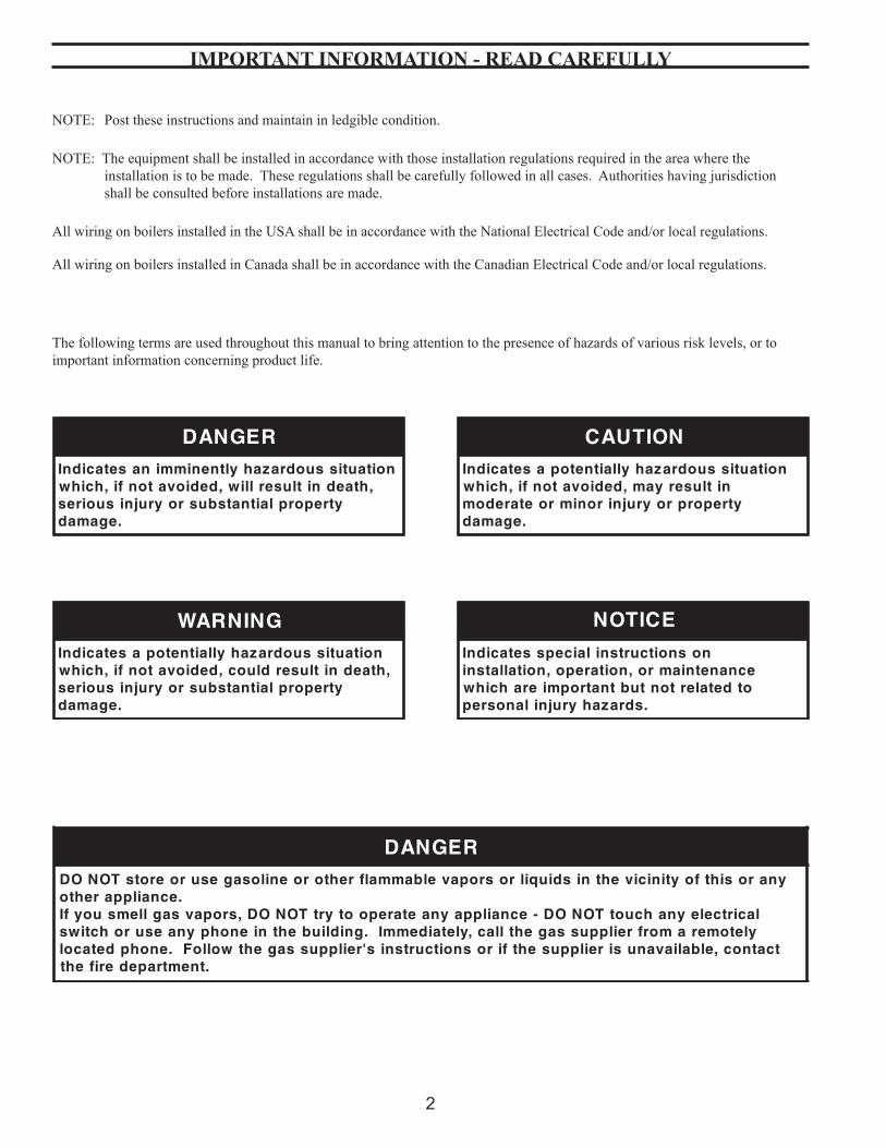
The following terms are used throughout this manual to bring attention to the presence of hazards of various risk levels, or to important information concerning product life.
IMPORTANT INFORMATION - READ CAREFULLY
NOTE: Post these instructions and maintain in ledgible condition.
NOTE: The equipment shall be installed in accordance with those installation regulations required in the area where the installation is to be made. These regulations shall be carefully followed in all cases. Authorities having jurisdiction shall be consulted before installations are made.
All wiring on boilers installed in the USA shall be in accordance with the National Electrical Code and/or local regulations.
All wiring on boilers installed in Canada shall be in accordance with the Canadian Electrical Code and/or local regulations.
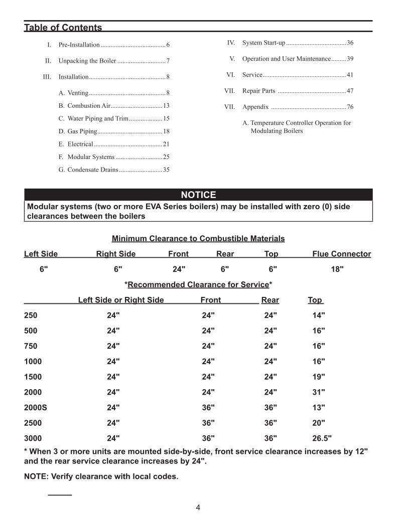
I. Pre-Installation .......................................6
II. Unpacking the Boiler .............................7
III. Installation ..............................................8
A. Venting ..............................................8
B. Combustion Air ...............................13
C. Water Piping and Trim ....................15
D. Gas Piping .......................................18
E. Electrical .........................................21
F. Modular Systems ............................25
G. Condensate Drains ..........................35
Table of Contents
Minimum Clearance to Combustible Materials
Left Side Right Side Front Rear Top Flue Connector
6" 6" 24" 6" 6" 18"
*Recommended Clearance for Service*
Left Side or Right Side Front Rear Top
250 24" 24" 24" 14"
500 24" 24" 24" 16"
750 24" 24" 24" 16"
1000 24" 24" 24" 16"
1500 24" 24" 24" 19"
2000 24" 24" 24" 31"
2000S 24" 36" 36" 13"
2500 24" 36" 36" 20"
3000 24" 36" 36" 26.5"* When 3 or more units are mounted side-by-side, front service clearance increases by 12" and the rear service clearance increases by 24".
NOTE: Verify clearance with local codes.
IV. System Start-up ....................................36
V. Operation and User Maintenance .........39
VI. Service ..................................................41
VII. Repair Parts .........................................47
VII. Appendix .............................................76
A. Temperature Controller Operation for Modulating Boilers
NOTICEModular systems (two or more EVA Series boilers) may be installed with zero (0) side clearances between the boilers
Form 102854-01 Rev. B Page 1 of 2 10/26/09
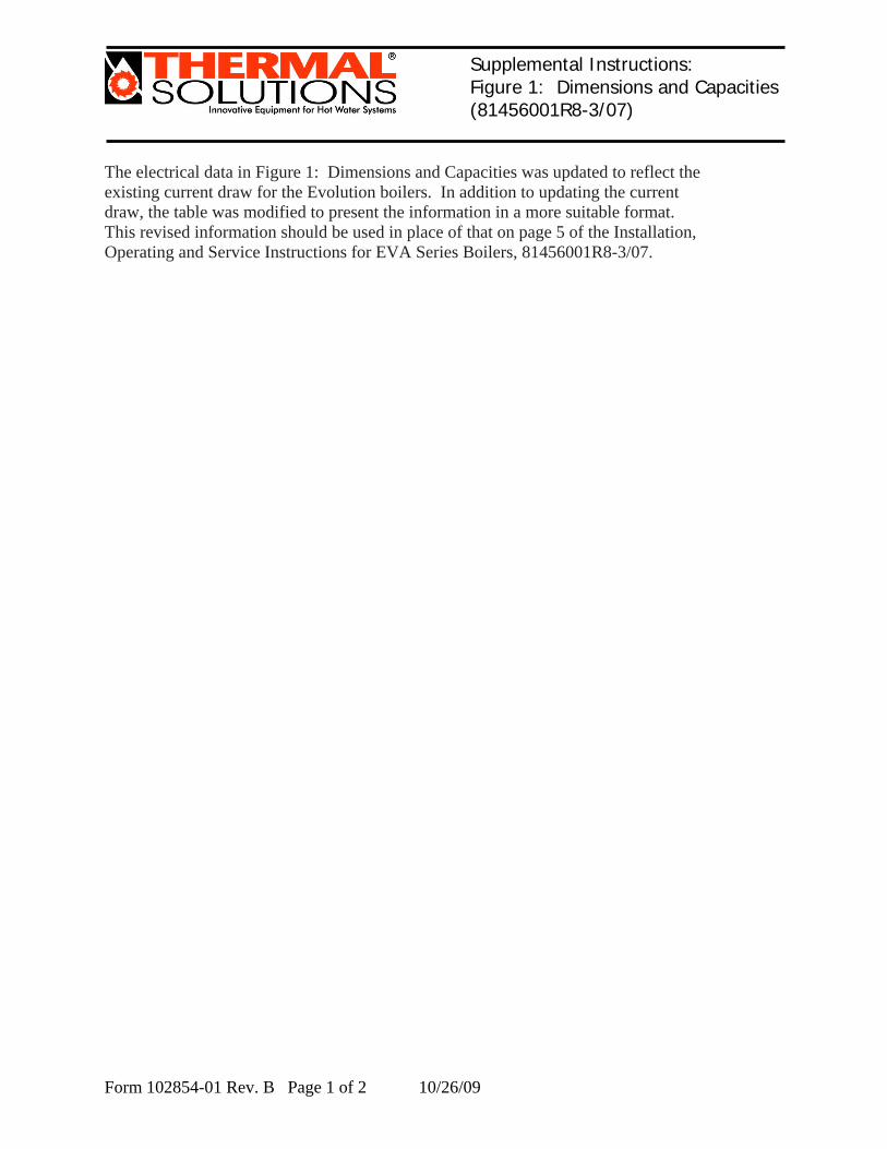
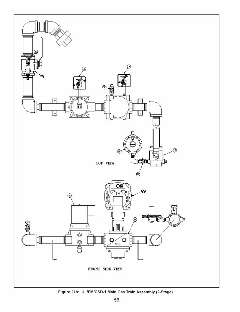
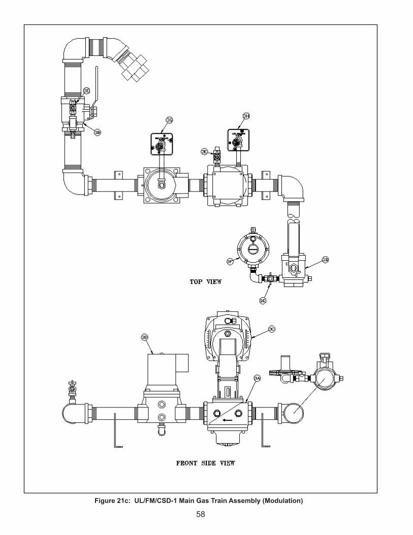
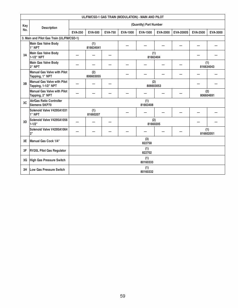
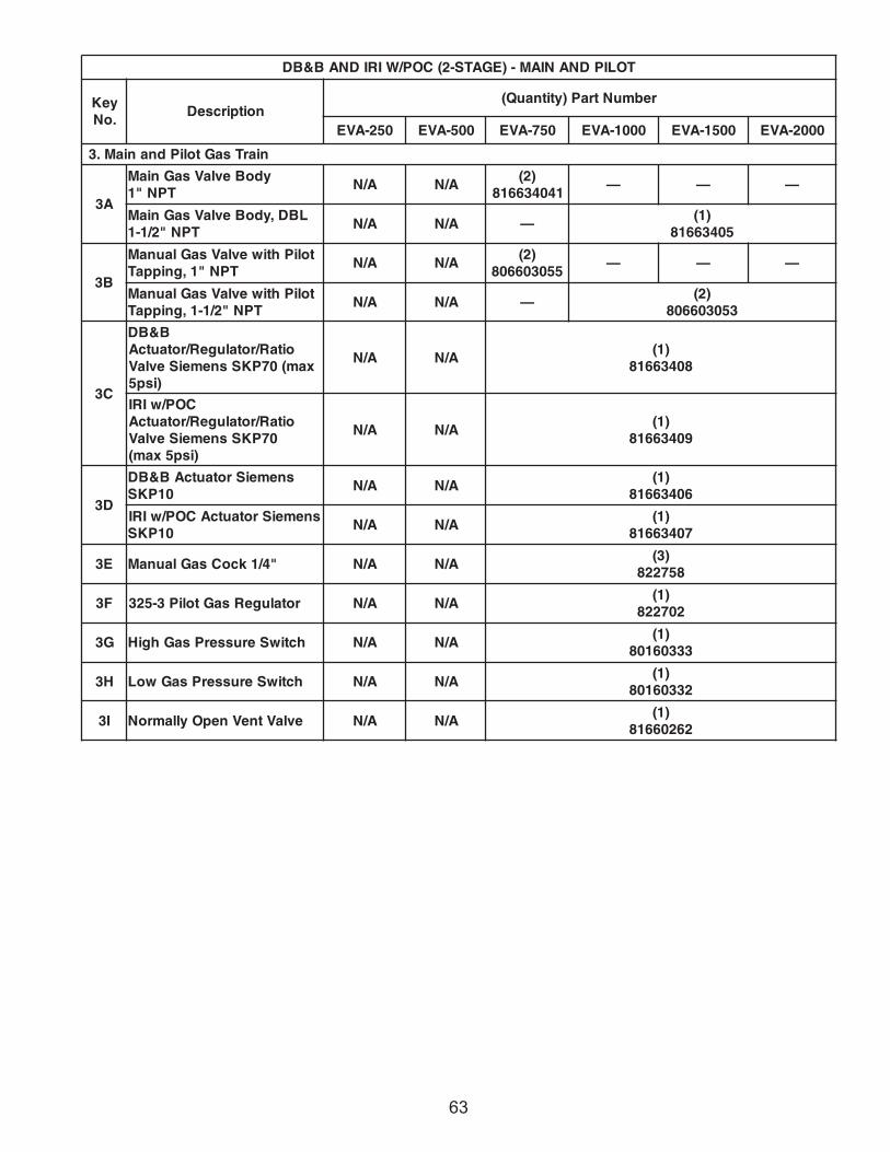
Supplemental Instructions: Figure 1: Dimensions and Capacities (81456001R8-3/07)
The electrical data in Figure 1: Dimensions and Capacities was updated to reflect the existing current draw for the Evolution boilers. In addition to updating the current draw, the table was modified to present the information in a more suitable format. This revised information should be used in place of that on page 5 of the Installation, Operating and Service Instructions for EVA Series Boilers, 81456001R8-3/07.
Form 102854-01 Rev. B Page 2 of 2 10/26/09
'H''L'
214
'U'
'G'
'S'
'E''F'
'K'
'R'
'W'
'A'
'B'
'C'
'V'
'Y'
'T''J'
'Z'
RE
QU
IRE
MEN
TFO
R B
UR
NER
REM
OV
AL'X
'
GAS
PIL
OT
1/4
O.D
. TU
BE
GAS
VE
NT
3/4
NPT
PIP
E
WA
TER
OU
TLE
T'M
' NP
T P
IPE
INLE
T AI
R'Q
' DIA
ME
TER
GA
LVA
NIZ
ED
DU
CT
CO
ND
ENS
ATE
DR
AIN
5/8
O.D
. TU
BE -
TO B
E P
IPE
D T
O A
NE
XTE
RN
AL
TRAP
BO
ILER
DR
AIN
1 N
PT
PIP
E
GA
S S
UP
PLY
'N' N
PT
PIP
E
WAT
ER IN
LET
'M' N
PT
PIPE
FLU
E O
UTL
ET'P
' DIA
ME
TER
SAF
-T-V
EN
T
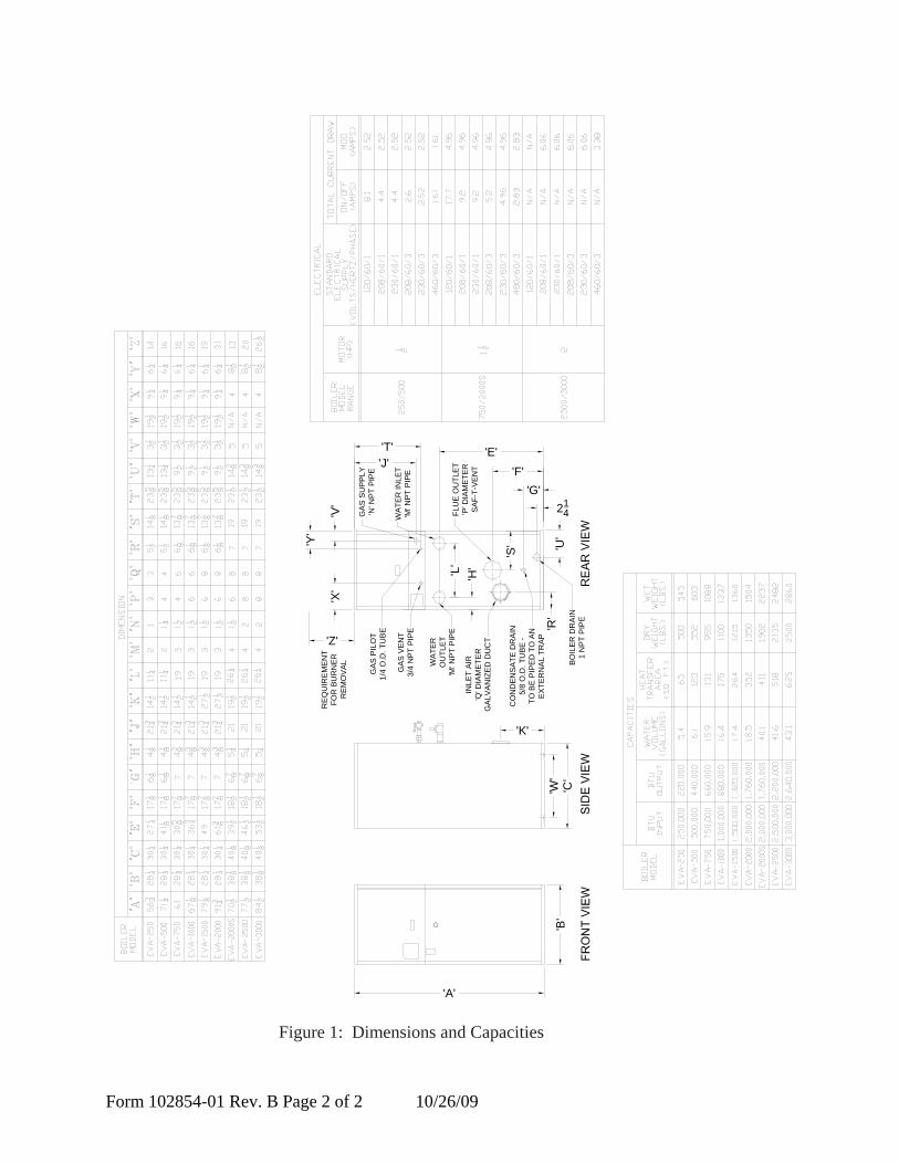
Figure 1: Dimensions and Capacities
�
6. For boiler located within unconfined space in building of unusually tight construction or within confined space, provide outdoor air through two permanent openings which communicate directly or by duct with the outdoors or spaces (crawl or attic) freely communicating with the outdoors. Locate one opening within 12 inches of top of space. Locate remaining opening within 12 inches of bottom of space. Minimum dimension of air opening is 3 inches. Size each opening per the following:
I. Pre-Installation
1. Determine volume of space (boiler room). Rooms communicating directly with space (through openings not furnished with doors) are considered part of space.
Volume [ft³] = Length [ft] x Width [ft] x Height [ft]
2. Determine Total Input of all appliances in space. Round result to nearest 1,000 Btu per hour (Btuh).
3. Determine type of space. Divide Volume by Total Input.
a. If result is greater than or equal to 50 ft³ per 1,000 Btuh, space is considered an unconfined space.
b. If result is less than 50 ft³ per 1,000 Btuh, space is considered a confined space.
4. Determine building type. A building of unusually tight construction has the following characteristics:
a. Walls and ceiling exposed to outside atmosphere have a continuous water vapor retarder with a rating of 1 perm or less with openings gasketed and sealed, and;
b. Weather-stripping has been added on openable windows and doors, and;
c. Caulking or sealants applied in joints around window and door frames, between sole plates and floors, between wall-ceiling joints, between wall panels, at plumbing and electrical penetrations, and at other openings.
5. For boiler located in an unconfined space in a building of other than unusually tight construction, adequate combustion and ventilation air is normally provided by fresh air infiltration through cracks around windows and doors.
A. Installation must conform to the requirements of the authority having jurisdiction. In the absence of such requirements, installation must conform to the National Fuel Gas Code, NFPA 54/ANSI Z223.1, and/or CAN/CGA B149 Installation Codes. Where required by the authority having jurisdiction, the installation must conform to the Standard for Controls and Safety Devices for Automatically Fired Boilers, ANSI/ASME CSD-1.
B. The boiler is not design certified for installation on combustible flooring. The boiler must not be installed on carpeting.
C. Provide clearance between boiler jacket and combustible material in accordance with local fire ordinance. Refer to page 4 of this manual for minimum listed clearance from combustible material.
D. Install on level floor. For basement installation provide concrete base if floor is not perfectly level or if water may be encountered on floor around boiler. Floor must be able to support weight of boiler, water and all additional system components.
E. Protect gas ignition system components from water (dripping, spraying, rain, etc.) during boiler operation and service (circulator replacement, condensate trap service, control replacement, etc.).
F. Provide combustion and ventilation air in accordance with applicable provisions of local building codes or: USA - National Fuel Gas Code, NFPA 54/ANSI Z223.1, Section 5.3, Air for Combustion and Ventilation; Canada - Natural Gas Installation Code, CAN/CGA - B149.1, or Propane Installation Code, CAN/CGA - B.149.2, Part 5, Venting Systems and Air Supply for Appliances.
The following guideline is based on the National Fuel Gas Code, NFPA 54/ANSI Z223.1.
E. Tilt the boiler to one side and slide a small roller under the raised base.
F. Tilt the boiler to the other side and slide another roller under the base.
Place a larger pipe roller on floor behind the skid.
G. Roll the boiler forward or backward off the skid and onto the pipe roller.
H. Move boiler to its permanent location.
A. Move boiler to approximate installed position.
B. Remove all crate fasteners.
C. Open outside container and remove all inside protective spacers and bracing.
D. Remove all boiler hold-down fasteners.
a. Direct communication with outdoors. Minimum free area of 1 square inch per 4,000 Btu per hour input of all equipment in space.
b. Vertical ducts. Minimum free area of 1 square inch per 4,000 Btu per hour input of all equipment in space. Duct cross-sectional area shall be same as opening free area.
c. Horizontal ducts. Minimum free area of 1 square inch per 2,000 Btu per hour input of all equipment in space. Duct cross-sectional area shall be same as opening free area.
Alternate method for boiler located within confined space. Use indoor air if two permanent openings communicate directly with additional space(s) of sufficient volume such that combined volume of all spaces meet criteria for unconfined space. Size each opening for minimum free area of 1 square inch per 1,000 Btu per hour input of all equipment in spaces, but not less than 100 square inches.
7. Ventilation Duct Louvers and Grilles. Equip outside openings with louvers to prevent entrance of rain and snow, and screens to prevent entrance of insects and rodents. Louvers and grilles must be fixed in open position or interlocked with equipment to open automatically before burner operation. Screens must not be smaller than ¼ inch mesh.
Consider the blocking effect of louvers, grilles and screens when calculating the opening size to provide the required free area. If free area of louver or grille is not known, assume wood louvers have 20-25 percent free area and metal louvers and grilles have 60-75 percent free area.
�
III. InstallationA. VENTING
1. General Guidelines
a. The vent system must be in accordance with the National Fuel Gas Code/NFPA 54 ANSI Z222.3, Part 7, Venting of Equipment or Applicable provisions of Local Building Codes.
b. All vent pipe must be adequately supported with vent supports no less than five (5) feet apart. The completed vent system must be rigid and able to withstand impacts without collapse.
c. This boiler requires AL29-4C® venting. Boiler is certified for use of single wall AL29-4C®
venting. Consult factory for any other venting materials.
d. This boiler may be operated with conventional, sidewall or vertical venting. Conventional vented appliances operate with negative pressure in the vent pipe. Sidewall and vertically vented boilers operate with positive pressure in the vent pipe. Positive pressure vent pipe can be mated to the boiler without any adapters.
e. Consult vent pipe manufacturer's instructions for minimum clearance to combustible material for vent components. In the absence of instructions, the minimum clearance to combustible material is six (6) inches.
f. Consult vent pipe manufacturer's instructions for proper method of sealing vent pipe sections and fittings. In the absence of instructions, make sure pipe and fittings are clean by swabbing with alcohol. Use Dow Corning 736 or 732 RTV, Polybar #500 RTV or Sil-bond 4500 or 6500 to seal vent pipe. Do not use other adhesives or sealants except as expressly permitted by the vent pipe manufacturer's instructions.
g. Refer to the appropriate drawings in this section of this manual to determine the proper configuration of venting system.
h. Consult vent pipe manufacturer's instructions for vent system assembly. Follow vent pipe manufacturer's instructions if those instructions conflict with this section.
i. Install vent system before installing air intake, water, gas or electrical connections.
2. IMPORTANT
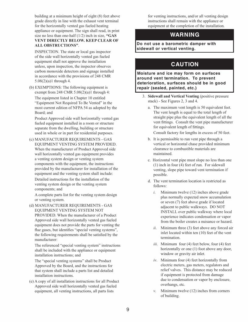
The Commonwealth of Massachusetts requires compliance with regulation 248 CMR 4.00 and 5.00 for installation of side-wall vented gas appliances as follows:
(a) For all side wall horizontally vented gas fueled equipment installed in every dwelling, building or structure used in whole or in part for residential purposes, including those owned or operated by the Commonwealth and where the side wall exhaust vent termination is less than seven (7) feet above finished grade in the area of the venting, including but not limited to decks and porches, the following requirements shall be satisfied:
INSTALLATION OF CARBON MONOXIDE DETECTORS. At the time of installation of the side wall horizontal vented gas fueled equipment, the installing plumber or gas fitter shall observe that a hard wired carbon monoxide detector with an alarm and battery back-up is installed on the floor level where the gas equipment is to be installed. In addition, the installing plumber or gas fitter shall observe that a battery operated or hard wired carbon monoxide detector with an alarm is installed on each additional level of the dwelling, building or structure served by the side wall horizontal vented gas fueled equipment. It shall be the responsibility of the property owner to secure the services of qualified licensed professionals for the installation of hard wired carbon monoxide detectors.
In the event that the side wall horizontally vented gas fueled equipment is installed in a crawl space or an attic, the hard wired carbon monoxide detector with alarm and battery back-up may be installed on the next adjacent floor level.
In the event that the requirements of this subdivision can not be met at the time of completion of installation, the owner shall have a period of thirty (30) days to comply with the above requirements; provided, however, that during said thirty (30) day period, a battery operated carbon monoxide detector with an alarm shall be installed.
APPROVED CARBON MONOXIDE DETECTORS. Each carbon monoxide detector as required in accordance with the above provisions shall comply with NFPA 720 and be ANSI/UL 2034 listed and IAS certified.
SIGNAGE. A metal or plastic identification plate shall be permanently mounted to the exterior of the
GNINRAWdezinavlaghtiwreliobsihtesutonoD
.smetsystnevdesab
GNINRAWreliobsihthtiwsrepmadtnevESUTONOD
.yrotcafybdezirohtuasselnu
�
building at a minimum height of eight (8) feet above grade directly in line with the exhaust vent terminal for the horizontally vented gas fueled heating appliance or equipment. The sign shall read, in print size no less than one-half (1/2) inch in size, “GAS VENT DIRECTLY BELOW. KEEP CLEAR OF ALL OBSTRUCTIONS”.
INSPECTION. The state or local gas inspector of the side wall horizontally vented gas fueled equipment shall not approve the installation unless, upon inspection, the inspector observes carbon monoxide detectors and signage installed in accordance with the provisions of 248 CMR 5.08(2)(a)1 through 4.
(b) EXEMPTIONS: The following equipment is exempt from 248 CMR 5.08(2)(a)1 through 4:
The equipment listed in Chapter 10 entitled “Equipment Not Required To Be Vented” in the most current edition of NFPA 54 as adopted by the Board; and
Product Approved side wall horizontally vented gas fueled equipment installed in a room or structure separate from the dwelling, building or structure used in whole or in part for residential purposes.
(c) MANUFACTURER REQUIREMENTS - GAS EQUIPMENT VENTING SYSTEM PROVIDED. When the manufacturer of Product Approved side wall horizontally vented gas equipment provides a venting system design or venting system components with the equipment, the instructions provided by the manufacturer for installation of the equipment and the venting system shall include:
Detailed instructions for the installation of the venting system design or the venting system components; and
A complete parts list for the venting system design or venting system.
(d) MANUFACTURER REQUIREMENTS - GAS EQUIPMENT VENTING SYSTEM NOT PROVIDED. When the manufacturer of a Product Approved side wall horizontally vented gas fueled equipment does not provide the parts for venting the flue gases, but identifies “special venting systems”, the following requirements shall be satisfied by the manufacturer:
The referenced “special venting system” instructions shall be included with the appliance or equipment installation instructions; and
The “special venting systems” shall be Product Approved by the Board, and the instructions for that system shall include a parts list and detailed installation instructions.
(e) A copy of all installation instructions for all Product Approved side wall horizontally vented gas fueled equipment, all venting instructions, all parts lists
for venting instructions, and/or all venting design instructions shall remain with the appliance or equipment at the completion of the installation.
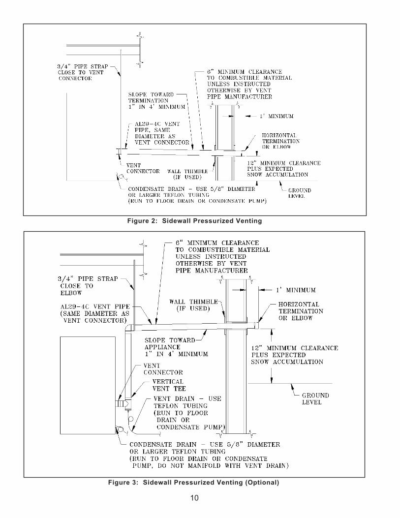
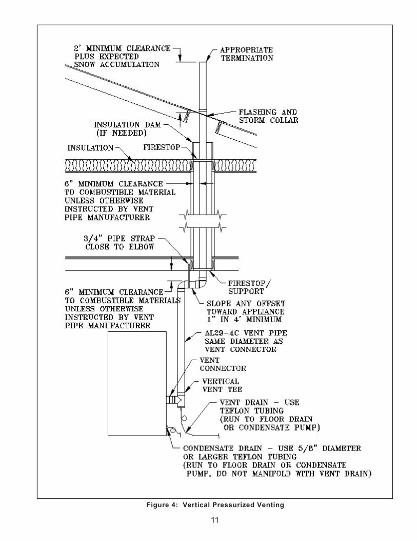
3. Sidewall and Vertical Venting (positive pressure stack) - See Figures 2, 3 and 4.a. The maximum vent length is 50 equivalent feet.
The vent length is equal to the total length of straight pipe plus the equivalent length of all the vent fittings. Consult the vent pipe manufacturer for equivalent length of fittings.
Consult factory for lengths in excess of 50 feet.b. It is permissible to run vent pipe through a
vertical or horizontal chase provided minimum clearance to combustible materials are maintained.
c. Horizontal vent pipe must slope no less than one (1) inch in four (4) feet of run. For sidewall venting, slope pipe toward vent termination if possible.
d. The vent termination location is restricted as follows:i. Minimum twelve (12) inches above grade
plus normally expected snow accumulation or seven (7) feet above grade if located adjacent to public walkways. DO NOT INSTALL over public walkway where local experience indicates condensation or vapor from the boiler creates a nuisance or hazard.
ii. Minimum three (3) feet above any forced air inlet located within ten (10) feet of the vent termination.
iii. Minimum four (4) feet below, four (4) feet horizontally or one (1) foot above any door, window or gravity air inlet.
iv. Minimum four (4) feet horizontally from electric meters, gas meters, regulators and relief valves. This distance may be reduced if equipment is protected from damage due to condensation or vapor by enclosure, overhangs, etc.
v. Minimum twelve (12) inches from corners of building.
�0
Figure 3: Sidewall Pressurized Venting (Optional)
Figure 2: Sidewall Pressurized Venting
��
Figure 4: Vertical Pressurized Venting
�2
4. Conventional Venting (Negative Draft) - See Figure 5.
a. The minimum chimney height is 15 feet.
b. The chimney must be protected from down drafts, rain and debris by using a chimney cap or star.
c. Start installing vent at vent cap and continue installation toward the boiler.
d. The flue connector and chimney flue diameter may need to be increased or decreased depending on the dimensions of the boiler. Consult the National Fuel Gas Code or Local Codes for sizing. Boiler input, flue connector lateral distance and chimney height affect the flue connector or chimney flue diameters.
e. A double acting barometric damper with integral flue spillage interlock switch must be used when the boiler is vented conventionally.
f. The chimney and flue connector must be sized and configured to provide a minimum - 0.04 inch w.c. draft at the vent outlet of the boiler.
g. Maintain a minimum vertical pitch of one (1) inch in four (4) feet of vent connector run.
Figure 5: Conventional Venting (Negative Draft)
e. Use appropriately designed thimbles when passing through combustible walls or roofs.
f. Install firestops where vent passes through floors, ceilings or framed walls. The firestop must close the opening between the vent pipe and the structure.
g. Enclose vent passing through occupied or unoccupied spaces above the boiler with materials having a fire resistance rating at least equal to the rating of the adjoining floor or ceiling. Maintain minimum clearance to combustible materials.
h. Locate vent terminal above combustion air intake terminal (if used) and no closer than one (1) foot horizontally.
i. Install vent terminal and work towards the boiler.j. Vertical venting requires flashing and a storm
collar to prevent moisture from entering the structure.
k. Vertical vent termination must be at least two (2) feet plus the expected snow accumulation above roof penetration height.
��
B. COMBUSTION AIR - See Figures 6 and 7.
1. The boiler may be operated with inside or outside air.
2. Refer to combustion air piping drawings in this section of this manual for proper outside air installation details.
3. Combustion air conduit can be galvanized smoke pipe, PVC, CPVC, or flexible aluminum conduit.
4. The maximum air inlet length is fifty (50) equivalent feet. Air inlet length is equal to the total length of straight pipe plus the equivalent length of fittings. Consult conduit manufacturer for equivalent length of fittings and pipe.
Consult factory for inlet lengths in excess of 50 feet.5. All joints and seams of the air intake pipe must be
sealed using Silicone caulk, such as RTV 732 or equivalent.
8. The air intake pipe must be adequately supported with straps or supports no less than five (5) feet apart. The completed air intake pipe system must be rigid and able to withstand impacts without collapse.
Figure 6: Horizontal Air Intake Piping
6. Air intake termination must be located at least twelve (12) inches above grade plus the expected snow accumulation.
7. Boiler may be installed with vertical venting and sidewall combustion air inlet or visa versa.
��Figure 7: Vertical Air Intake Piping
��
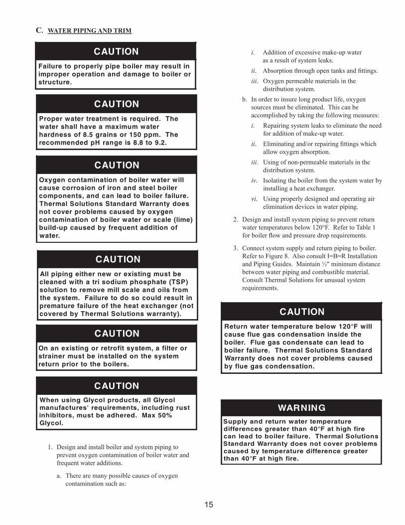
1. Design and install boiler and system piping to prevent oxygen contamination of boiler water and frequent water additions.
a. There are many possible causes of oxygen contamination such as:
i. Addition of excessive make-up water as a result of system leaks.
ii. Absorption through open tanks and fittings.iii. Oxygen permeable materials in the
distribution system.b. In order to insure long product life, oxygen
sources must be eliminated. This can be accomplished by taking the following measures:i. Repairing system leaks to eliminate the need
for addition of make-up water.ii. Eliminating and/or repairing fittings which
allow oxygen absorption.iii. Using of non-permeable materials in the
distribution system.iv. Isolating the boiler from the system water by
installing a heat exchanger.vi. Using properly designed and operating air
elimination devices in water piping.
2. Design and install system piping to prevent return water temperatures below 120°F. Refer to Table 1 for boiler flow and pressure drop requirements.
3. Connect system supply and return piping to boiler. Refer to Figure 8. Also consult I=B=R Installation and Piping Guides. Maintain ½" minimum distance between water piping and combustible material. Consult Thermal Solutions for unusual system requirements.
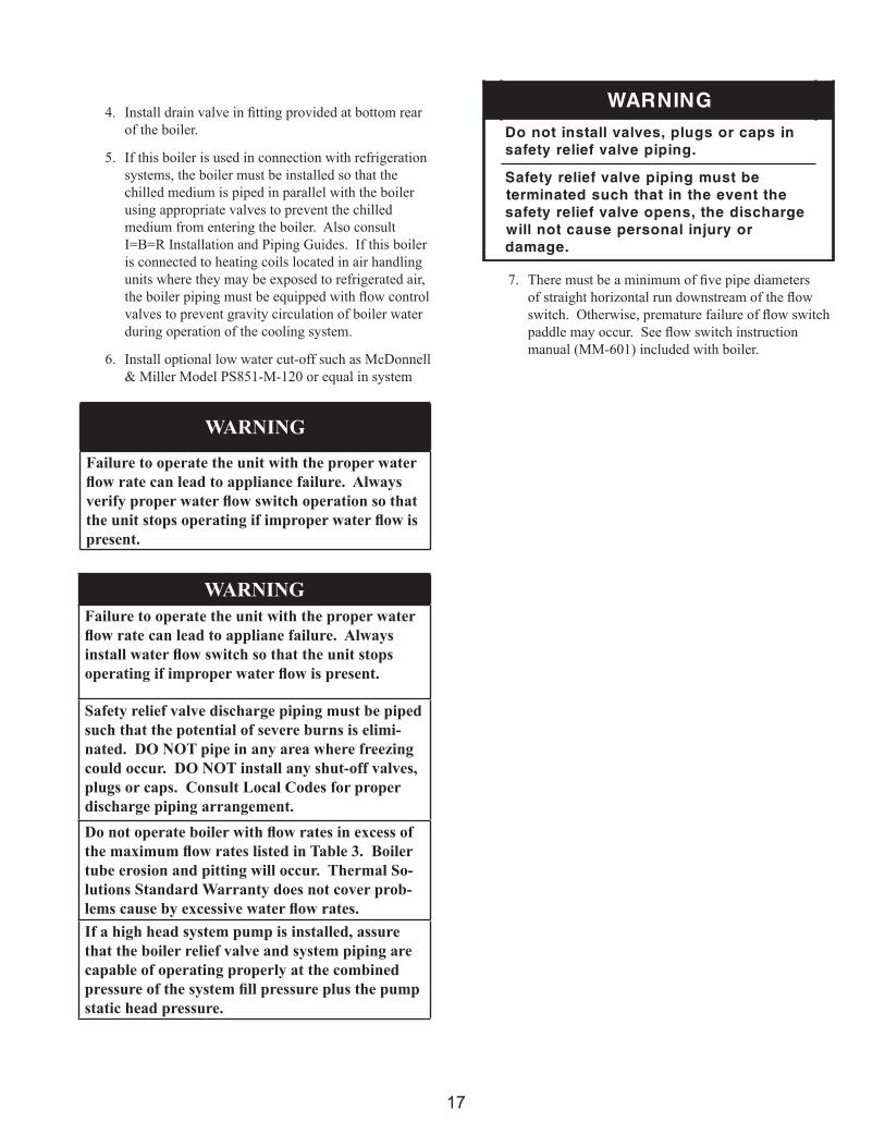
4. Install drain valve in fitting provided at bottom rear of the boiler.
5. If this boiler is used in connection with refrigeration systems, the boiler must be installed so that the chilled medium is piped in parallel with the boiler using appropriate valves to prevent the chilled medium from entering the boiler. Also consult I=B=R Installation and Piping Guides. If this boiler is connected to heating coils located in air handling units where they may be exposed to refrigerated air, the boiler piping must be equipped with flow control valves to prevent gravity circulation of boiler water during operation of the cooling system.
6. Install optional low water cut-off such as McDonnell & Miller Model PS851-M-120 or equal in system
7. There must be a minimum of five pipe diameters of straight horizontal run downstream of the flow switch. Otherwise, premature failure of flow switch paddle may occur. See flow switch instruction manual (MM-601) included with boiler.
WARNING
Failure to operate the unit with the proper water flow rate can lead to appliance failure. Always verify proper water flow switch operation so that the unit stops operating if improper water flow is present.
WARNINGFailure to operate the unit with the proper water flow rate can lead to appliane failure. Always install water flow switch so that the unit stops operating if improper water flow is present.
Safety relief valve discharge piping must be piped such that the potential of severe burns is elimi-nated. DO NOT pipe in any area where freezing could occur. DO NOT install any shut-off valves, plugs or caps. Consult Local Codes for proper discharge piping arrangement.Do not operate boiler with flow rates in excess of the maximum flow rates listed in Table 3. Boiler tube erosion and pitting will occur. Thermal So-lutions Standard Warranty does not cover prob-lems cause by excessive water flow rates.If a high head system pump is installed, assure that the boiler relief valve and system piping are capable of operating properly at the combined pressure of the system fill pressure plus the pump static head pressure.
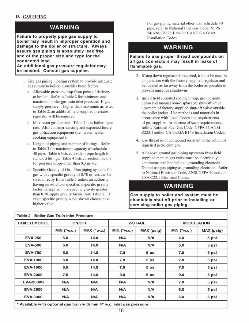
1. Size gas piping. Design system to provide adequate gas supply to boiler. Consider these factors.a. Allowable pressure drop from point of delivery
to boiler. Refer to Table 2 for minimum and maximum boiler gas train inlet pressure. If gas supply pressure is higher than maximum as listed in Table 2, an additinal field supplied pressure regulator will be required.
b. Maximum gas demand. Table 7 lists boiler input rate. Also consider existing and expected future gas utilization equipment (i.e., water heater, cooking equipment).
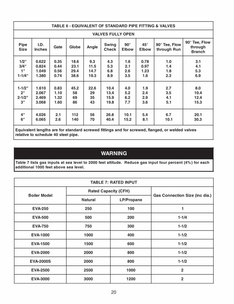
c. Length of piping and number of fittings. Refer to Table 3 for maximum capacity of schedule 40 pipe. Table 6 lists equivalent pipe length for standard fittings. Table 4 lists correction factors for pressure drops other than 0.3 in w.c.
d. Specific Gravity of Gas. Gas piping systems for gas with a specific gravity of 0.70 or less can be sized directly from Table 3 unless an authority having jurisdiction, specifies a specific gravity factor be applied. For specific gravity greater than 0.70, apply gravity factor from Table 5. If exact specific gravity is not shown choose next higher value.
For gas piping material other than schedule 40 pipe, refer to National Fuel Gas Code, NFPA 54/ANSI Z223.1 and/or CAN/CGA B149 Installation Codes.
2. If step down regulator is required, it must be used in conjunction with the factory supplied regulator and be located as far away from the boiler as possible to prevent nuisence shutdowns.
3. Install field supplied sediment trap, ground-joint union and manual non-displacable shut-off valve upstream of factory supplied shut-off valve outside the boiler jacket. Use methods and materials in accordance with Local Codes and requirements of gas supplier. In absence of such requirements, follow National Fuel Gas Code, NFPA 54/ANSI Z223.1 and/or CAN/CGA B149 Installation Codes.
4. Use thread joint compound resistant to the action of liquefied petroleum gas.
5. All above ground gas piping upstream from field supplied manual gas valve must be electrically continuous and bonded to a grounding electrode. Do not use gas piping as grounding electrode. Refer to National Electrical Code, ANSI/NFPA 70 and /or CSA C22.1 Electrical Codes.
6. Pressure test. The boiler and its gas connection must be leak tested before placing boiler in operation.
a. Protect boiler gas control valve. For all testing over ½ psig, boiler and its individual shutoff valve must be disconnected from gas supply piping. For testing at ½ psig or less, isolate boiler from gas supply piping by closing boiler's individual manual shutoff valve.
b. Locate leaks using approved combustible gas detector, soap and water, or similar nonflammable solution.
1. General. Install wiring and ground boiler in accordance with authority having jurisdiction or in absence of such requirements National Electrical Code, ANSI/NFPA 70 and/or CSA C22.1 Electrical Code.
2. Connect the main power supply and ground from fused disconnect to proper boiler electrical leads located in the junction box at the rear of the boiler. Refer to electrical consumption plate on boiler jacket.
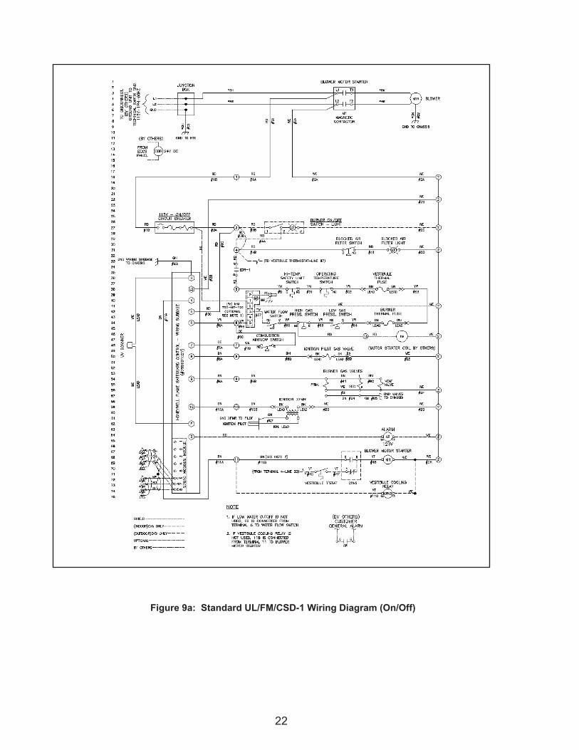
3. Remove factory supplied jumper wire from terminals 4 and 5. Connect field supplied safety limits or devices (low water cut-off, temperature limit etc.) in series using proper terminals provided in boiler electrical cabinet. Refer to wiring diagram supplied with boiler for wiring information. Refer to Figures 9a, 9b, and 9c, for typical wiring diagrams. Refer to Figure 1, for electrical requirements for
5. Following pages have sample wiring diagrams. Contact Thermal Solutions Representative or visit website (www.thermalsolutions.com) for current wiring options.
6. An as-built wiring diagram is included with every boiler when it ships.
22
Figure 9a: Standard UL/FM/CSD-1 Wiring Diagram (On/Off)
2�
Figure 9b: Standard UL/FM/CSD-1 Wiring Diagram (2-Stage)
2�
Figure 9c: Standard UL/FM/CSD-1 Wiring Diagram (Modulation)
2�
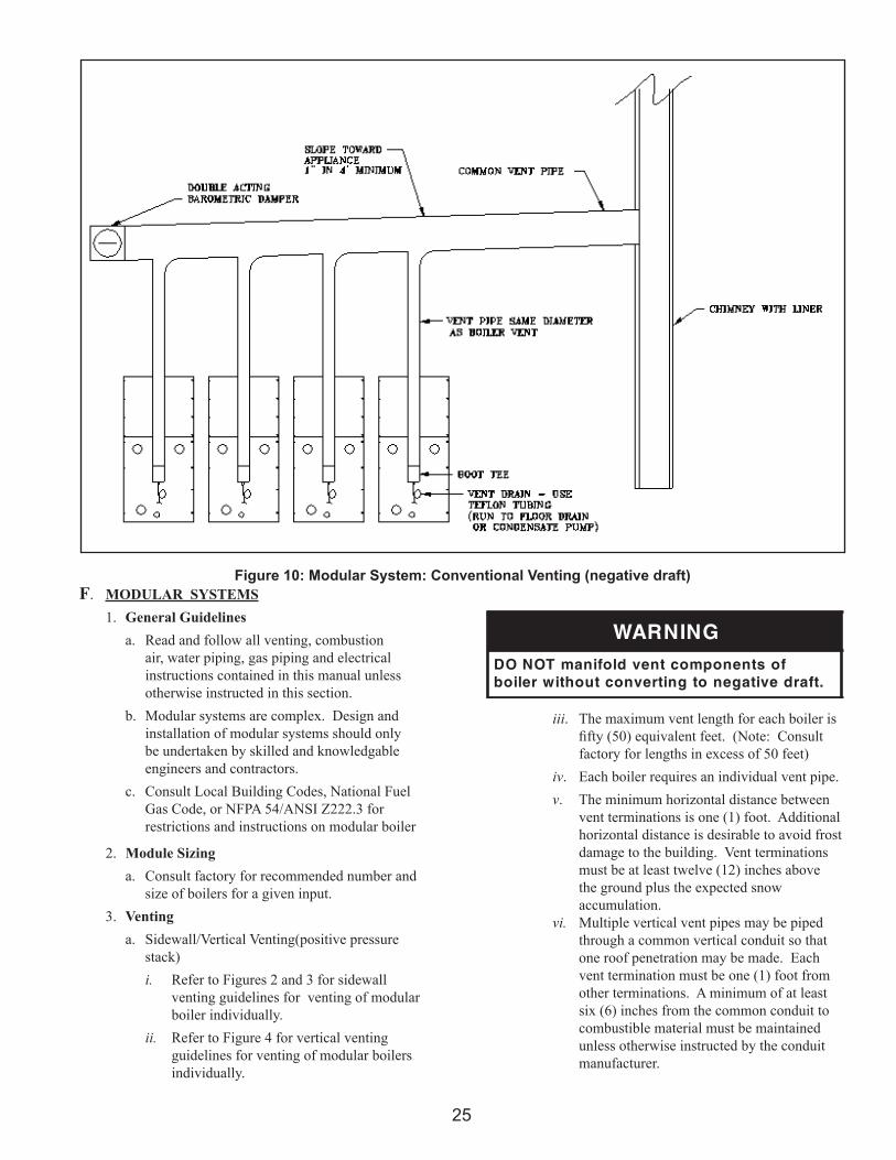
Figure 10: Modular System: Conventional Venting (negative draft)F. MODULAR SYSTEMS
1. General Guidelinesa. Read and follow all venting, combustion
air, water piping, gas piping and electrical instructions contained in this manual unless otherwise instructed in this section.
b. Modular systems are complex. Design and installation of modular systems should only be undertaken by skilled and knowledgable engineers and contractors.
c. Consult Local Building Codes, National Fuel Gas Code, or NFPA 54/ANSI Z222.3 for restrictions and instructions on modular boiler
2. Module Sizinga. Consult factory for recommended number and
size of boilers for a given input.3. Venting
a. Sidewall/Vertical Venting(positive pressure stack)i. Refer to Figures 2 and 3 for sidewall
venting guidelines for venting of modular boiler individually.
ii. Refer to Figure 4 for vertical venting guidelines for venting of modular boilers individually.
GNINRAWfostnenopmoctnevdlofinamTONOD
.tfardevitagenotgnitrevnoctuohtiwreliob
iii. The maximum vent length for each boiler is fifty (50) equivalent feet. (Note: Consult factory for lengths in excess of 50 feet)
iv. Each boiler requires an individual vent pipe.v. The minimum horizontal distance between
vent terminations is one (1) foot. Additional horizontal distance is desirable to avoid frost damage to the building. Vent terminations must be at least twelve (12) inches above the ground plus the expected snow accumulation.
vi. Multiple vertical vent pipes may be piped through a common vertical conduit so that one roof penetration may be made. Each vent termination must be one (1) foot from other terminations. A minimum of at least six (6) inches from the common conduit to combustible material must be maintained unless otherwise instructed by the conduit manufacturer.
b. Conventional Venting (Negative Draft)i. Refer to Figure 10 for conventional venting
guideline for modular boilers.ii. Use only AL29-4C or 316 L and 304 L
stainless steel vent components.iii. Refer to National Fuel Gas Code to
determine required chimney diameter and common venting diameter. Note that combined input, lateral length and chimney height affect vent diameter.
iv. A single double acting barometric damper can be utilized on the common venting when venting according to Figure 10.
v. Slope common venting a minimum of one (1) inch in four feet of run towards boilers.
vi. Locate boiler(s) with lowest input closest to chimney.
4. Air Intake Pipinga. Consult factory for common air intake pipe
sizing.b. Refer to Figures 11 and 12 for common air intake
guidelines for modular boilers.c. Individual air intake pipes may be used in lieu of
common air intake piping.d. The maximum air intake length is fifty (50)
equivalent feet. Common air intake straight lengths and fittings should be assumed to have the equivalent length the same as an individual air intake pipe, used for a given boiler intake pipe diameter. (Note: Consult factory for lengths in excess of 50 feet)
e. Position horizontal air intake termination center line below horizontal vent termination's center line.
f. Vertical air intake pipe must terminate at least
ECITONekatnirianommocrofyrotcaftlusnoC
.gnizis
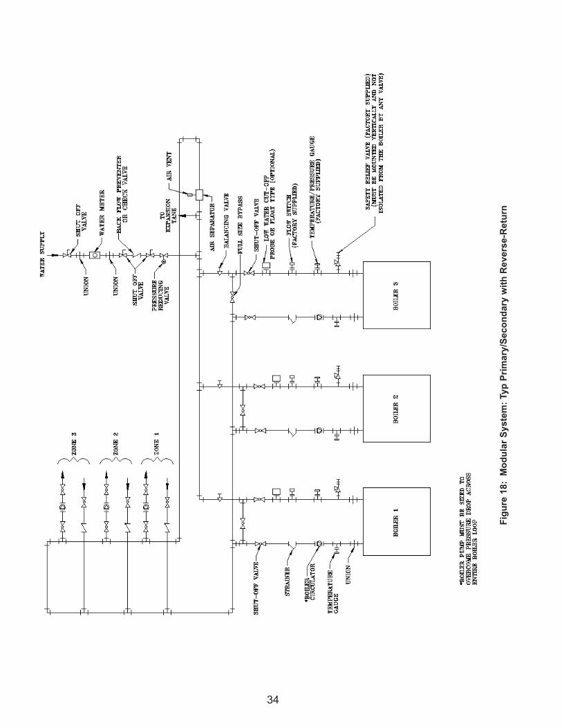
5. Water Pipinga. Refer to Figures 13 thru 18 for typical water
piping for modular boilers.b. Installing a low water cut-off in the system
piping is highly recommended and may be required by Code.
c. Refer to Table 1 for pressure drop and flow requirements for each boiler.
6. Gas Pipinga. Refer to National Fuel Gas Code, Local Codes
7. Electricala. Each boiler must be provided with a dedicated
fused disconnect.b. Install wiring and ground boiler in accordance
with requirements of authority having jurisdiction. In absence of such requirements, the National Electrical Code, ANSI/NFPA 70 and/or CSA C22.1 Electrical Code.
c. Install each circulator with a separate fused disconnect switch. Refer to circulator manufacturer's data for electrical requirements.
d. Refer to Figure 1 for electrical data for each size boiler.
8. Condensate Pipinga. Each boiler requires separate condensate drains.
In addition, most venting configurations require separate condensate drains in the vent system. Do not manifold boiler drains or vent drains together.
b. Refer to Section G for condensate removal system.
G. CONDENSATE DRAINS1. Each boiler contains a condensate drain. In
addition, most vent configurations require a drain tee located in the vent piping. Pipe each condensate drain separately to a floor drain or condensate pump/sump.
2. Use continuous Teflon or high temperature resistant silicone tubing for condensate piping. Do not install fittings on condensate lines.
3. Each condensate drain must contain a siphon/pigtail to prevent flue gas flow through the condensate piping.
4. A common condensate pump/sump may be used. Run separate piping from each condensate drain to the sump. A common drain may be used to discharge condensate from the sump. Consult pump/sump manufacturer for compatibility of pump/sump materials of construction. If a common sump is used, individual drain lines should be connected such that one drain cannot back feed into another drain.
5. Consult local authorities regarding disposal of flue gas condensate into public waste water system. Some jurisdictions require that the condensate be buffered before discharge. This buffering is commonly achieved by draining the condensate through a limestone bed. Consult a chemical treatment company for buffering systems.
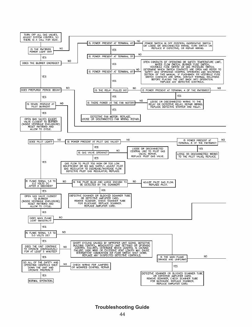
A. Verify that the venting, water piping, gas piping and electrical system are installed properly. Refer to installation instructions contained in this manual.
B. Confirm all electrical, water and gas supplies are turned off at the source and that chimney/vent is clear of obstructions. If boiler is controlled by an external control system, this system must be temporarily disconnected. The local boiler controls should be allowed to operate the boiler.
C. Remove the upper front jacket panel.
D. Confirm that all manual shut-off gas valves between the boiler and gas supply are closed.
E. Fill boiler and system with water to desired cold fill pressure. Fully open supply and return water valves and fully close bypass balancing valve. See Figure 8.
F. Confirm that the boiler and system have no water leaks.
G. Turn on electrical supply to the boiler and circulation system at fused disconnect switches. Note that there is electrical power at certain components even with the power switch off. See wiring diagrams in Figures 9a, 9b, and 9c.
H. Turn system circulators on and purge air from the boiler and system piping.
I. Confirm that water flow switch is operating properly.
J. Turn on gas supply to the boiler gas piping.
K. Confirm that the supply pressure to the gas regulator supplied with the boiler conforms to Table 2 for maximum and minimum supply pressures.
L. Open the manual gas shut-off valves located upstream of the gas regulator supplied with the boiler. Do not open manual gas valve inside of boiler jacket.
M. Using soap solution, or similar non-combustible solution, electronic leak detector or other approved method, check that boiler gas piping valves, regulators and all other components are leak free. Eliminate any leaks.
N. Purge gas line of air.
O. Reset low gas pressure safety switch.
P. Turn on control circuit breaker inside front jacket panel. Note that the flame safeguard is powered even with the power switch off.
Q. Turn boiler operating switch to the on position.
R. Allow boiler to complete prepurge and trial for ignition period. Once pilot flame is recognized by controller, position flame control switch to test position.
S. Look through the boiler sight glass and confirm that pilot flame is blue and steady and that the flame signal is between 1.5 and 5.0 volts DC. Adjust pilot gas regulator until proper pilot manifold gas pressure is achieved per firetest report label. Pilot flame should be blue with very little yellow.
T. Turn the boiler off, place flame control switch in "run" position, and repeat Steps R., and S. at least five times until reliable pilot ignition and signal is achieved and confirmed.
U. With the pilot operating properly, allow boiler to continue to trial for main flame. Confirm that the flame control locks out on main flame failure.
V. Open the manual main gas shut-off valve located inside the boiler jacket.
W. Using the procedure detailed in Step M, leak test gas piping and valves inside of jacket. Eliminate any leaks.
X. Reset flame safeguard and allow boiler to run through prepurge, trial for pilot and trial for main flame.
Y. Confirm that main flame ignites smoothly. Observe main flame and confirm that burner element is evenly orange without flickering. Observe flame signal and confirm signal is between 1.5 and 5.0 volts DC.
Z. Turn boiler off and repeat Steps X and Y at least five times to confirm proper main burner operation.
AA. With main flame on, at high fire, measure gas pressure downstream of the main gas valves and adjust to the manifold pressure indicated on the factory firetest label.
BB. Confirm that high and low gas pressure switches are functioning and are adjusted to prevent over firing or under firing of the boiler.
CC. Adjust setting of air filter flow switch by rotating knob on switch counter clockwise until change filter light switch is illuminated. Turn switch knob clockwise ¼ turn past the point where the change filter light goes out. Replace upper front jacket panel.
DD. With boiler running and all panels attached, measure oxygen (O2) and carbon monoxide (CO) concentrations in the flue gas and flue gas temperature. Compare results with values given on factory firetest report supplied with the boiler.
EE. Verify that all safety and operating limits and flame controls are operating properly. These controls and limits include combustion air switch, water temperature operating control, manual reset water temperature safety limit, vestibule fuseable link, mixer fuseable link, high and low gas pressure switches. Refer to manuals for these components for proper start-up and operating instructions. Follow all instructions contained in these manuals. This manual was provided with the boiler.
FF. Set Operating Limits - To set the operating boiler water temperature for on/off and 2-Stage boiler, rotate the dial of the "operating" aquastat to the appropriate temperature setting. 2-Stage boiler operation—set the "firing rate" aquastat at 20°F below the "operating" aquastat at initial start-up. Adjust "firing rate" set point to accomodate field requirements. To set the operating boiler water temperature for modulating boilers refer to Appendix A - Digital Temperature Controller for Modulating Boilers.
GG. Replace access panels and turn boiler off. Allow system and boiler water to cool.
HH. After boiler and system water has cooled to less than 80°F, turn boiler on and observe the return water temperature from the system. If the return water temperature rises to above 120°F in less than five (5) minutes, leave the bypass balancing valve fully closed. If return water temperature is not above 120°F or it takes a longer period than five (5) minutes to rise above 120°F, slowly open bypass balancing valve. See Figure 8. Continue to open bypass balancing valve so that return water temperature to the boiler is above 140°F. Note that if the temperature does not rise above 140°F with the bypass valve fully open, slowly begin to close balancing valve in the system and return piping until boiler water return temperature is above 140°F. Turn boiler off and allow boiler and system water to cool to less than 80°F. Turn boiler on and note return water temperature to the boiler. Confirm
that water temperature rises above 120°F in less than five (5) minutes. If not, continue to open bypass balancing valve. Modulating boilers utilize a PID digital temperature control, where the set point cannot be set lower than 140°F, using a 5°F lower differential setting, for 20°F DT.
II. When water adjustment is complete, allow boiler to operate and confirm proper operation. Place system control back in normal operation.
JJ. Contact reputable chemical treatment company for recommendations on proper water treatment for the installation. Each installation is different and must be analyzed based on local water conditions and boiler operating schedule. The treatment chemicals must be compatible with copper, bronze, steel and cast iron materials of construction.
A. This boiler is equipped with an ignition device which automatically lights the pilot. Do not try to light the pilot by hand.
B. BEFORE OPERATING smell all around the boiler area for gas. Be sure to smell next to the floor because some gas is heavier than air and will settle on the floor.
V. Operation and User Maintenance
FOR YOUR SAFETY, READ BEFORE OPERATING
1. STOP! Read all the safety information (warnings, cautions etc.) in this manual.
2. Set system control so that there is no call for heat to the boiler.
3. This boiler is equipped with an ignition device which automatically lights the pilot and main burner. Do not try to light the pilot or main flame by hand.
4. Locate the operating switch located on the front of the boiler.
5. Move the switch to the "on" position.
6. Set system control so that there is a call for heat from the system.
7. Observe prepurge, pilot ignition and main flame ignition.
8. If pilot or main flame ignition does not occur during initial attempt, remove the upper front jacket panel of the boiler. If the boiler pilot and main flame light, go to Step 10.
LIGHTING INSTRUCTIONS
WHAT TO DO IF YOU SMELL GAS• Do not try to light any boiler or other appliance.• Do not touch any electric switch; do not use any
phone in your building.• Immediately call your gas supplier from a
remotely located phone. Follow the gas supplier’s instructions.
• If you cannot reach your gas supplier, call the fire department.
C. Do not use this boiler if any part has been in contact with water. Immediately call a qualified service technician to inspect the boiler and to replace any part of the control system and any gas control which has been in contact with water.
9. Reset the burner control by pressing the reset button located on the burner control. If you do not know where the control reset button is, do not touch any part of the control system or wiring. Turn all gas and electrical power off to the boiler and call a qualified service technician.
10. Replace the upper front jacket panel.
11. Observe several on and off cycles of the boiler. If any light offs are excessively noisy or rough, or any questionable boiler operation is noticed, immediately turn off all gas and electrical power and call qualified service technician.
• Set control system so there is no call for heat to the boiler.
• Turn off all electrical power to the boiler if service is to be performed.
• Locate the operating switch on the front of the boiler.
• Move the operating switch to the “off” position.
12. The following maintenance must be performed by the boiler operator on a daily basis when the boiler is operating.
a. Observe burner color.b. Check flame control for proper operation and
shutdown.c. Check vent and air intake piping for any
obstructions.d. Check for any water leaks.e. Check for any gas leaks.f. Check condensate drains for any obstructions.g. Clean any debris or trash from boiler area.h. Log that the above maintenance was completed
in a boiler log. Maintain log near boiler location.
Limits and operating controls such as safety and operating temperature limits, water flow switch, thermal fuse switches and high/low gas pressure switch contacts must be closed to initiate and continue burner sequence. Flame signal must not be present. Airflow switch must be open.
Control terminal � is energized and all safety and operating control contacts are closed. Control terminal � is energized to start the combustion air fan.
Contacts close when fan generates enough differential air pressure to actuate combustion air flow switch diaphragm.
Fan purges combustion chamber and venting for �0 seconds.
Pilot gas valve(s) and ignition transformer are energized. Pilot gas flows to pilot burner and is ignited.
Ignition transformer is de-energized after 5 seconds. Presence of pilot flame is detected by ultraviolet scanner. Flame signal exceeds �.� volts DC.
Main gas valves are energized. Gas flows to main burner and is ignited by pilot flame. Pilot and main flames are detected by ultraviolet scanner. Flame signal continues to maintain �.� to �.0 volts DC.
After 5 seconds, pilot gas valve(s) is de-energized. Gas flow to pilot stops. Pilot flame is extinguished. Main flame is detected by ultraviolet scanner. Flame signal continues to maintain �.� to �.0 volts DC.
Main burner continues to operate until call for heat ends, contacts of a safety or operating control open, electrical power is interrupted, or the flame signal drops below �.� volts DC. 2-Stage and Modulating boilers operate based on the load, determined by the difference between the bulk boiler water temperature and the boiler water set point.
Main gas valves are de-energized. Gas flow to main burner stops. Main flame is extinguished. Fan continues to operate for 60 seconds to evacuate combustion chamber and venting.
Boiler in Standby
Call for Heat
Combustion Air Flow Switch Contacts Make
Pilot Flame Establishing Period Begins
Early Spark Termination
Main Flame Establishing Period Begins
Run Period Begins
Run Period
Post Purge
Standby
30 sec.
5 sec.
5 sec.
3 sec.
Prepurge Begins
After �0 seconds fan stops.
��
PERIODIC MAINTENANCE RECOMMENDED CHECK LISTFrequency Component/Item Recommended Test
Daily Maintenance
Gauges, monitors, and indicators Make visual inspection and record readings.
Gauges, monitors, and indicators Check operation of boiler is as shown on page (��) of this manual.
Burner flame Make visual inspection of burner flame.
Low Draft, fan air pressure, and damper position interlocks
Test low draft, fan, air pressure, and damper position interlocks according to instructions if so equipped
Weekly Maintenance
Igniter Make visual inspection, check flame signal strength; log
Flame signal strength Read and log flame signal meter, read for both pilot and main flames
Flame failure detection system Close manual fuel supply for (�) pilot, (2) main fuel cock, and/or valve(s); check safety shutdown timing
Firing rate controlCheck firing rate control, place RWF40 in manual mode and check high and low firing settings for proper operation
Pilot and/or main fuel valvesOpen limit switch and make aural and visual check; check valve position indicators and check fuel meters if so fitted
Low-water fuel cutoff Test low-water fuel cutoff device and alarm according to manufacturer’s instructions
Monthly Maintenance
Flue, vent, stack, or outlet dampers Check components
Gas pressure interlocks Test high and low gas pressure interlocks
Semi-Annual Maintenance
Gauges, monitors, and indicators Recalibrate all indicating and recording gauges
Flame failure detection system Check components
Condensate drain tubes Check drain tubes have liquid in trap and condensate is properly directed
Air filter Check air filter
Interlocks and valves Check piping and wiring of all interlocks and shut off valves if so equipped
Annual Maintenance
Flue, vent, stack, or outlet dampers Measure carbon monoxide and oxygen levels and temperature in flue products
Flame failure detection systemConduct pilot turndown test according to manufacturer’s instructions. This test is required annually and after any adjustments to flame scanner mount or pilot burner
Pilot and/or main fuel valves Check all coils and diaphragms; test other operating parts of all safety shutoff and control valves
Pilot and/or main fuel valves Perform leakage test on pilot and main gas and/or oil fuel valves, in accordance with instructions
Flame safeguard Test purge timing according to manufacturer’s instructions
Air Filter Replace (recommended)
Boiler trim Remove lower front jacket panel and check for any signs of corrosion and leaks
High limit and operating temp. controls Test proper operation
As-RequiredLow-water fuel cutoff Recondition or replace
Safety relief valves Test safety relief valves in accordance with ASME Boiler and Pressure Vessel Code, Sections VI and VII
��
Air Filter: A. Perform a visual inspection of air filter and replace as necessary 1. Remove upper front fanel 2. Remove red tube from nipple on filter assembly 3. Remove wing nut 4. Remove filter assembly from boiler 5. Remove foam pre-filter and wash with soap
and water 6. Replace primary filter as necessary
Pilot and Main Flame: A. Perform a visual inspection of pilot burner flame.
1. Refer to the flame safeguard instruction manual and conduct a pilot turndown test. 2. Observe pilot operation and record pilot signal. Flame should be steady medium hard blue clearly visible through sight glass.
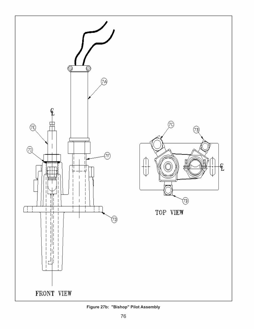
B. Pilot Cleaning and Maintenance 1. Shut off gas supply and disconnect electrical service. 2. Disconnect scanner, ignition electrode, loosen and remove pilot gas line and combustion air line from fan. 3. Remove mounting fasteners and pull pilot assembly from heat exchanger. 4. Examine pilot electrode and set gap to 1/8” if needed. Clean as required. 5. Reassemble in reverse order using a new gasket available from Thermal Solutions. C. Perform a visual inspection of main burner flame. 1. Observe main flame and record flame signal. Flame should be steady deep orange in color with dark blue checkerboard pattern throughout. 2. Main burner requires no cleaning or annual maintenance
Check Combustion and Safety Controls: A. Check flame failure detection system with system operating. 1. Pilot a. Refer to the flame safeguard instruction
manual b. Manually close pilot fuel supply and
verify lock out of primary control. 2. Main Flame a. Refer to the flame safeguard instruction b. Close manual main fuel shut off valve
and verify lockout of primary control.
Burner: A. No maintenance or inspection is required.
��
VII. Repair Parts
EVA Series repair parts can be ordered through your nearest Thermal Solutions Representative for delivery from Lancaster, PA.
The Representatives can also advise as to the availability of product and repair parts from local sources.
Contact Thermal Solutions for your Representative at:
VIII Appendix A –Temperature Controller Operation for Modulating Boilers
A. DescriptionThe microprocessor based temperature controller is utilized for all modulating Thermal Solutions water boilers. The basic function of the controller is to modulate the firing rate of the burner in response to the boiler heat load. The controller monitors the boiler water temperature through the use of a sensor located in the boiler pressure vessel. The controller compares the boiler water temperature to the controller’s user defined operating set-point temperature.
An output signal from the microprocessor varies the blower speed through the use of a variable frequency drive (VFD). The gas valve regulates an appropriate amount of gas flow for a given air flow or blower speed. The user may adjust the operating set-point temperature for a given application. In addition, the controller has the ability to change to an alternate set-point through an external signal for low load conditions (i.e. weekend use, night setback). Outdoor reset is another standard feature, allowing the boiler operating temperature to vary based on the outdoor ambient temperature. The typical result is a higher seasonal efficiency.
Other features include:
B. Set-UpAll of the control parameters have been set at the factory. There are a few parameters called “Process Parameters” that must be defined by a qualified operator. The table below will help serve as a reference and record when making adjustments.
��
Actual Value (red display)
Setpoint Value(green display)
Burner On
Decrease Value
Programming Key
Indicates ManualOperation
Limit Comparator
Increase Value
EXIT Key
s t
s t
To alter any of these process parameters follow the following steps:• To obtain access into the programming mode of the controller, briefly press the button “PGM”.• You will see “SP1” displayed on the second line in green LEDs. The previously set operating temperature will be
displayed on the first line in red LEDs. To increase or decrease the setpoint 1 value (SP1) use the up and down arrow keys respectively ( ).
• To set the value for “SP2”, briefly press the “PGM” key and follow the same instructions above.• To return to the operating mode press “EXIT”, otherwise the unit will automatically return to the operating mode
after 30 seconds of no activity.
To make other adjustments, contact your local representative or consult the factory.
C. AdjustmentsOften during troubleshooting conditions it may become necessary to manually adjust the firing rate. Follow the instructions below to make manual firing rate adjustments.
• Press “EXIT” button and hold for 5 -10 seconds.• The red light above manual operation (hand) symbol illuminates.• Press button to raise firing rate. Press button to lower firing rate.• 0 = 50% of Maximum firing rate and 100 = 100% of Maximum firing rate• Press “EXIT” button and hold for 5 –10 seconds to return to automatic firing rate control.• Automatic mode has been re-activated once the red light above the manual operation symbol goes out.
D. OtherSystem Specifications
Input voltage————————100-240vac 48/63hzEnvironmental————————Nema 4 external, Internal 95%rh noncondensingTransducer supply—————24VDC, 30ma Analog Input 1————————Pt100,Ni100, Thermocouple (J, K, T or N),4-20ma and Analog 0-10vAnalog Input 2————————1k pot,4-20ma, 0-1VDC, 0-10 VDCAnalog Input 3————————Pt100,Ni100 Temperature sensorsOutput 1 release to modulate-24-240VAC 2Amps maxOutput 2 and 3 open/close——24-240VAC 2Amps maxOutput 4 programmable———24-240VAC 2Amps maxOutput 5 analog output————0-10 VDC (500 ohm load min), 0-20 or 4-20ma (500ohm load max) Mod bus rtu port———————9600 Baud, unit Address 1-99Data storage——————————EEPROM Approvals———————————UL, CSA, CE
�0
NOTES
��
NOTES
�2
Thermal Solutions("seller")
LIMITED WARRANTYLIMITED WARRANTY
Subject to the terms and conditions herein and except as provided below with respect to products or parts not manufactured by Thermal Solutions, Seller warrants to the original owner at the original installation site that products manufactured by Seller (“Products”) comply, at the time of manufacture, the heat exchanger with recognized hydronics industry regulatory agency standards and requirements then in effect and will be free from defects in materials and workmanship for a period of 3 years from date of shipment (the “Warranty Period”). The burner is also covered under the limited warranty for 10 years from date of shipment (the "Warranty" Period). SPECIAL NOTE: The warranty of any boiler found to be operating as a “Water Heater” shall revert back to Thermal Solution’s standard water heater warranty.For products or parts not manufactured by Thermal Solutions, the warranty obligations of Thermal Solutions shall, in all respects, be limited to one year.
REMEDY
A. The sole remedy for breach of this warranty is expressly limited to the repair or replacement of any part found to be defective under conditions of normal use within the Warranty Period. Labor for removal and/or installation is not included.
B. Warranty - The owner must notify the original installer of the Product and Seller (Attention: Thermal Solutions, P.O. Box 3244, Lancaster, PA 17604-3244), in writing, within the Warranty Period, providing a detailed description of all claimed defects. Transportation to a factory or other designated facility for repairs of any products or items alleged defective shall, in all events, be the responsibility and at the cost of the owner.
EXCLUSIONS
Seller shall have no liability for and this warranty does not cover:A. Incidental, special or consequential damages, such as
loss of the use of products, facilities or production, inconvenience, loss of time or labor expense involved in repairing or replacing the alleged defective Product.
B. The performance of any Product under conditions varying materially from those under which such Product is usually tested under industry standards as of the time of shipment.
C. Any damage to the Product due to abrasion, erosion, corrosion, deterioration, abnormal temperatures or the influence of foreign matter or energy.
D. The design or operation of owner’s plant or equipment or of any facility or system of which any Product may be made a part.
E. The suitability of any Product for any particular application.
F. Any failure resulting from misuse, modification not authorized by Seller in writing, improper installation or
lack of or improper maintenance.G. Equipment furnished by the owner, either mounted or
unmounted, or when contracted for by the owner to be installed or handled.
H. Leakage or other malfunction caused by:1. Defective installations in general and specifically, any
installation which is made:a. in violation of applicable state or local plumbing
housing or building codes, b. without a certified ASME, pressure relief valve, orc. contrary to the written instructions furnished with
the unit2. Adverse local conditions in general and, specifically,
sediment or lime precipitation in the tubes and/or headers or corrosive elements in the atmosphere.
3. Misuse in general and, specifically, operation and maintenance contrary to the written instructions furnished with the unit, disconnection, alteration or addition of components or apparatus, not approved by seller, operation with fuels or settings other than those set forth on the rating plate or accidental or exterior damage.
I. Production of noise, odors, discoloration or rusty water.J. Damage to surrounding area or property caused by leakage
or malfunction.K. Costs associated with the replacement and/or repair
of the unit including: any freight, shipping or delivery charges, any removal, installation or reinstallation charges, any material and/or permits required for installation reinstallation or repair, charges to return the boiler and or components.
Seller’s liability under this warranty shall not in any case exceed the amount paid for the Product found to be defective.THIRD-PARTY WARRANTIES
For goods or components not manufactured by Seller, the warranty obligations of Seller shall, in all respects, conform and be limited to one year from the date of shipment
SEVERABILITY
To the extent that any provision of this warranty would be void or prohibited under applicable law, such provisions shall be limited in effect to the minimum extent necessary to render the remaining provisions hereof enforceable.