Edition April 2008 PRIMEQUEST 500A/500/400 Series Installation Manual (errata 2006/10/10, 2008/09/19, 2008/12/18 and 2009/0224 incorporated) Please note the table of corrections (errata) 2009/6/18 at the end of the manual.
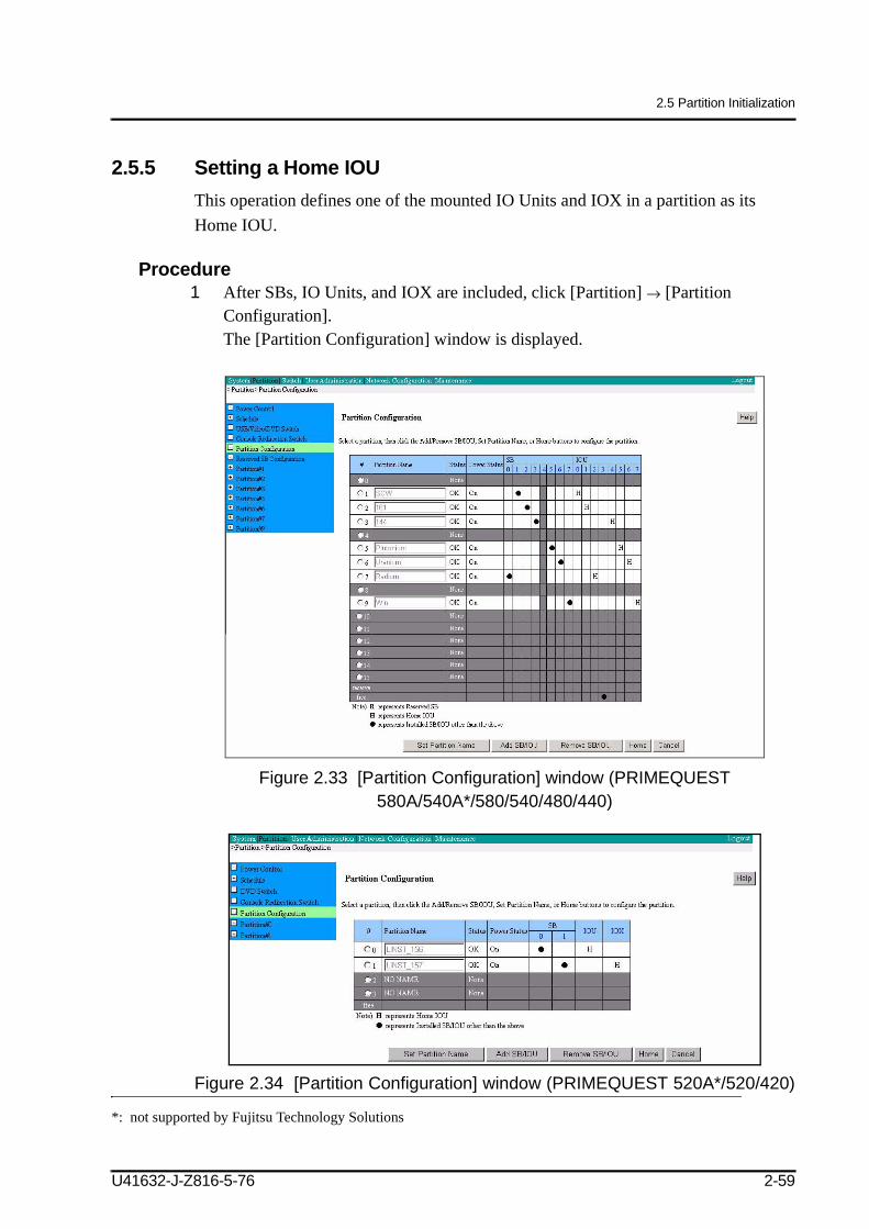
Transcript
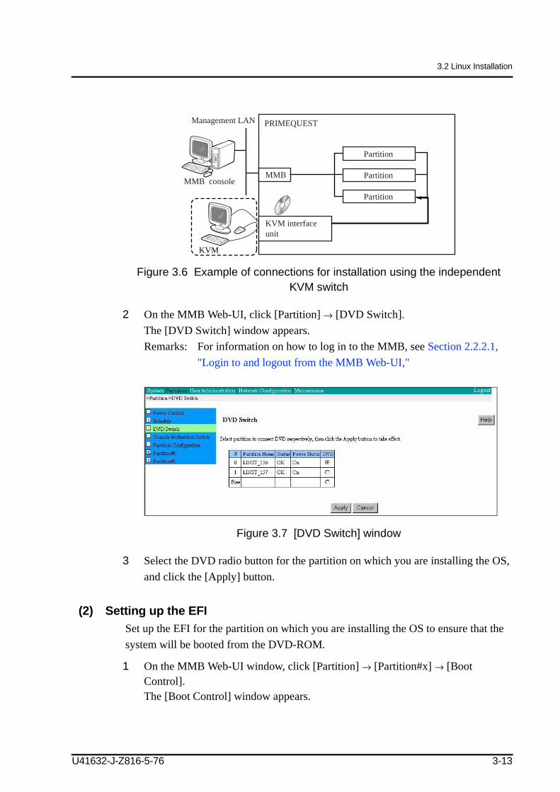
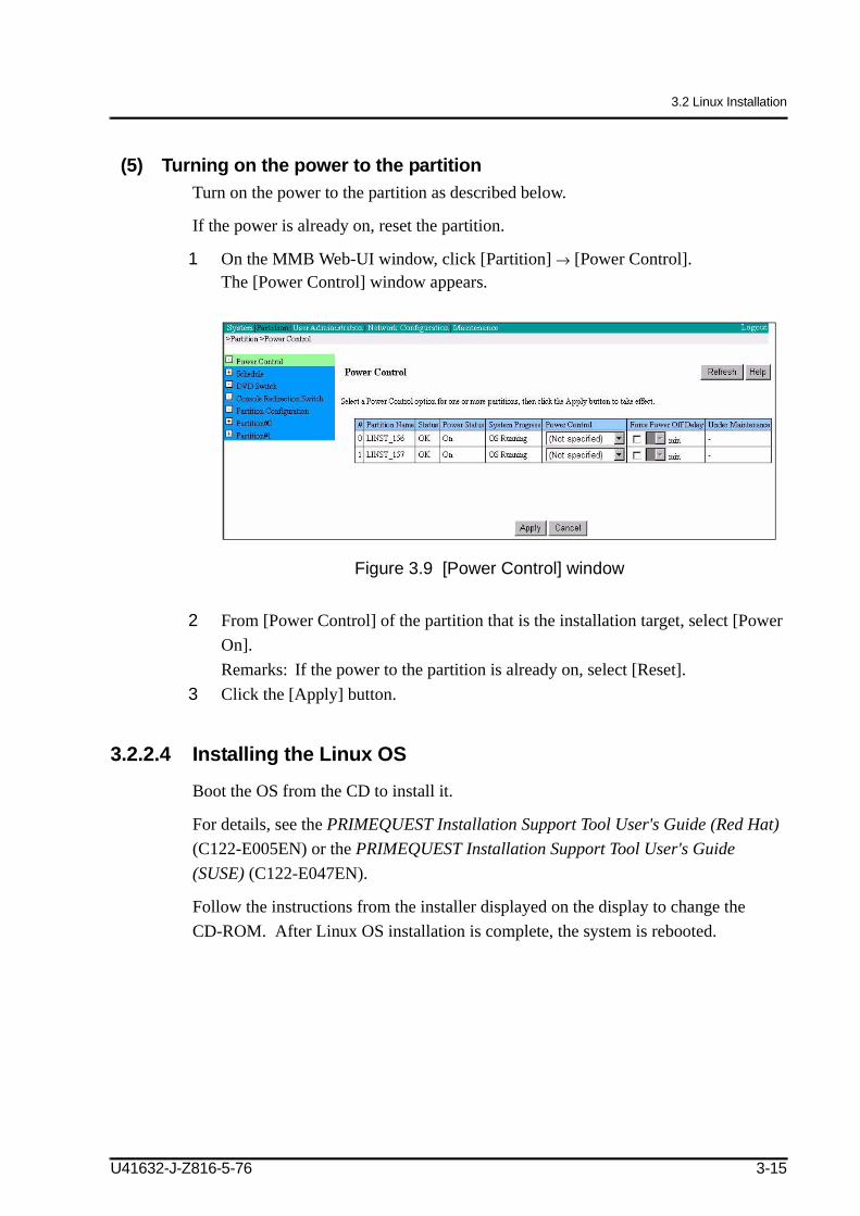
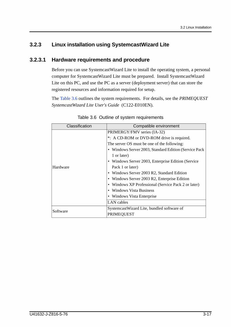
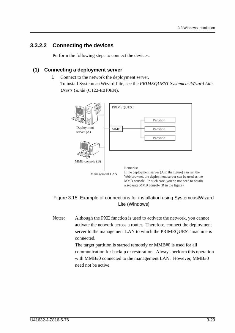
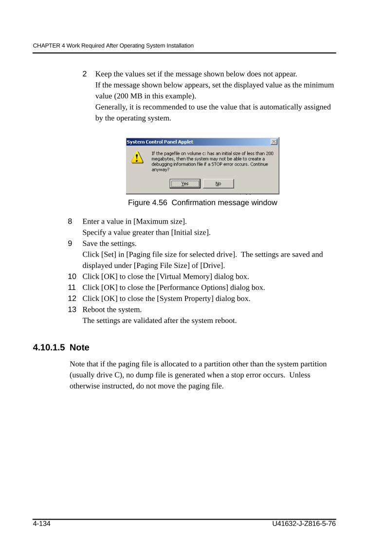
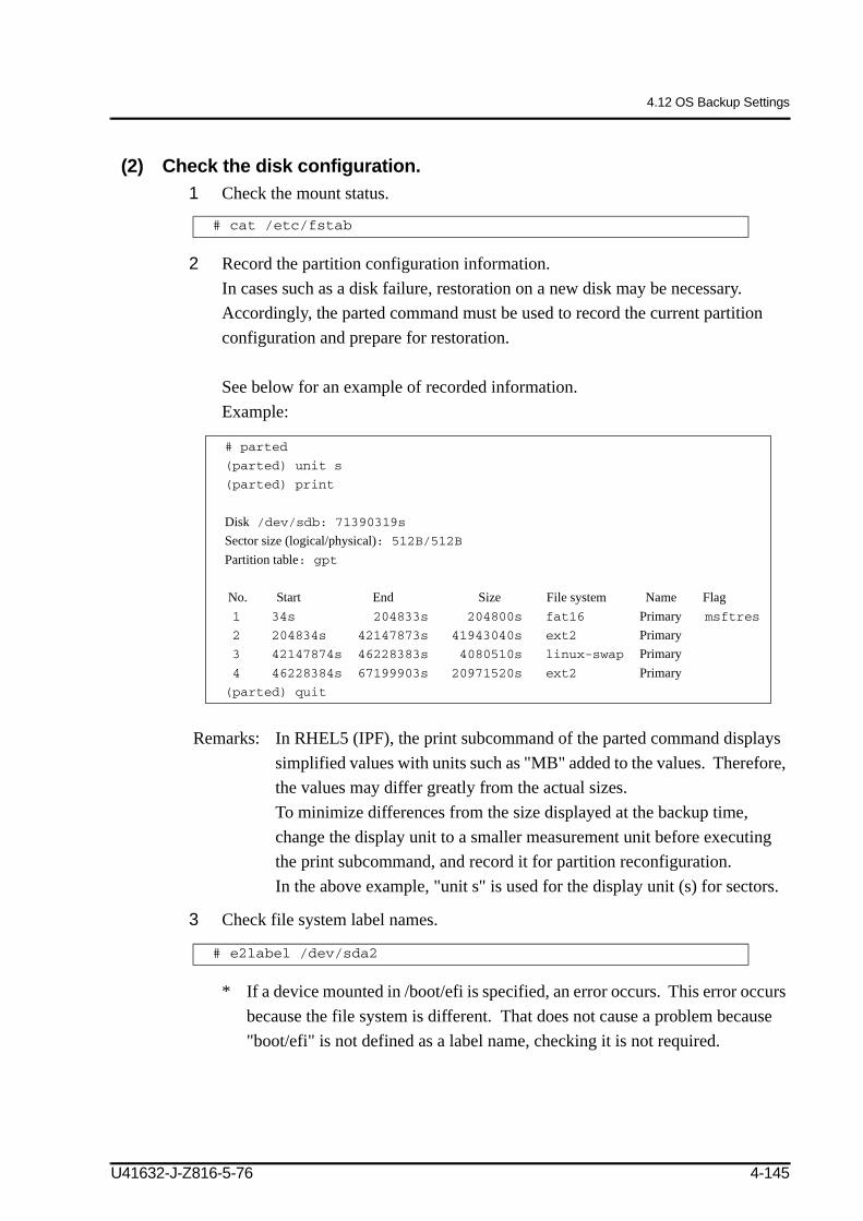
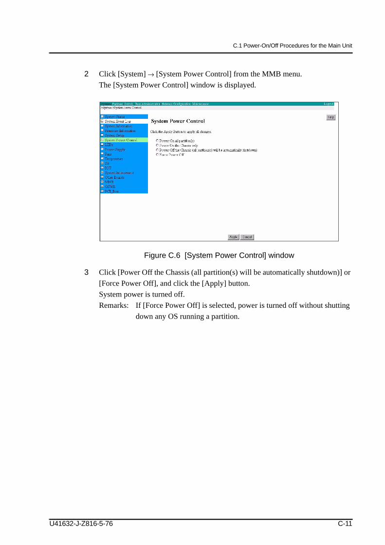
Edition April 2008
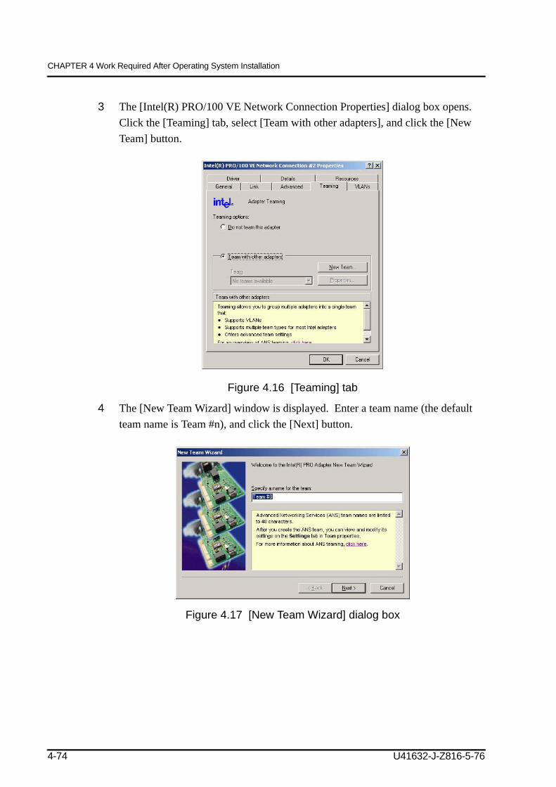
PRIMEQUEST 500A/500/400 Series Installation Manual
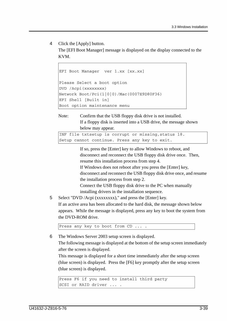
(errata 2006/10/10, 2008/09/19, 2008/12/18 and 2009/0224 incorporated)
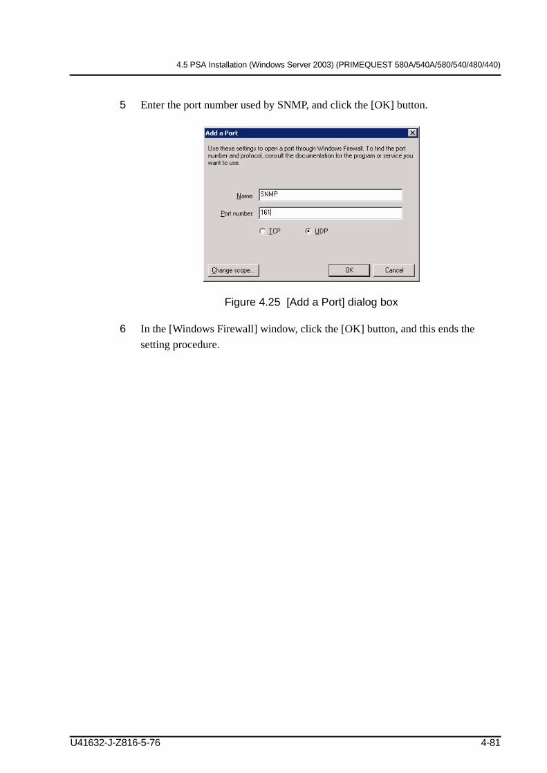
Please note the table of corrections (errata) 2009/6/18 at the end of the manual.
Comments… Suggestions… Corrections…The User Documentation Department would like to know your opinion on this manual. Your feedback helps us to optimize our documentation to suit your individual needs.
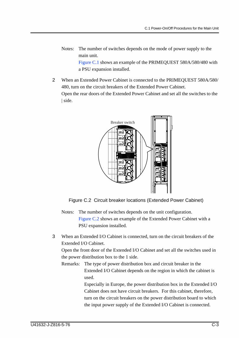
Fax forms for sending us your comments are included at the back of the manual.
There you will also find the addresses of the relevant User Documentation Department.
All rights reserved.Delivery subject to availability; right of technical modifications reserved.
All hardware and software names used are trademarks of their respective manufacturers.
Environmental protection and serviceThe PRIMEQUEST systems have a long life expectancy, not only because of the excellent expansion options they offer, but also because of the quality of the products.
As technology continues to develop, however, ever greater volumes of data will need to be processed. More and more demands are being placed on storage capacity, speed and computer system design. So when you eventually want to replace your PRIMEQUEST system with a newer model and dispose of the old device, we can also offer you support in this area.
Recycling old computer equipment is already a tradition at Fujitsu Technology Solutions: We have been redeeming and reusing old computer systems for many years now. Even at the design stage, particular emphasis is placed on the reusability of components and materials.
Your PRIMEQUEST system is manufactured to the greatest possible extent from environ-mentally friendly materials that can be fully recycled.
Read on through the next sections for a brief look at some of the measures we have intro-duced in an effort to protect the environment as well as our tips and suggestions for environ-mentally friendly handling of your system.
Environmentally friendly product design and development
This product has been designed in accordance with Fujitsu Technology Solutions Guideline FSC 03230 “environmentally friendly product design and development”.
This means that the designers have taken into account critical factors such as durability, selection of materials and coding, emissions, packaging, the ease with which the product can be dismantled and the extent to which it can be recycled.
This saves resources and thus reduces the harm done to the environment.
Production and development of the PRIMEQUEST systems are certified in accordance with the environment management system DIN ISO 14001.
Note on saving energy
If your device does not have to remain switched on permanently, only switch it on when you are ready to use it and then switch it off again during long breaks and when you finish your work.
1
Environmental protection and service
Note on dealing with consumables
Please dispose of printer consumables and batteries in accordance with local government regulations.
Note on labeling plastic housing parts
Please avoid sticking your own labels on plastic housing parts wherever possible, since this makes it difficult to recycle them.
Take-back, recycling and disposal
Our remarketing and recycling center is certified in accordance with the ECO Audit Regulation of the European Community. Contact it for details on redeeming and reusing devices and consumables within Europe:
In case of a technical problem with Fujitsu Technology Solutions products, or If you have questions on setup or operation: our technical support specialists can offer fast and competent assistance: http://www.ts.fujitsu.com/support/helpdesk.html
You will also find information here on products, telephone numbers, etc.
The Call Management Center (CMC) can be reached in Germany as follows:
DE Dieses Gerät ist entsprechend der europäischen Richtlinie 2002/96/EGüber Elektro- und Elektronikaltgeräte (waste electrical and electronic equipment - WEEE) gekennzeichnet. Die Richtlinie gibt den Rahmen für eine EU-weit gültige Rücknahme und Verwertung der Altgeräte vor.
EN This appliance is labelled in accordance with European Directive 2002/96/EG concerning used electrical and electronic appliances (waste electrical and electronic equipment - WEEE). The guideline determines the framework for the return and recycling of used appliances as applicable throughout the EU.
AR 2002/96/(waste electrical and electronic equipment - WEEE).
.BG 2002/96/EG
(waste electrical and electronic equipment - WEEE).
CS Tento spot ebi je ozna en v souladu s evropskou sm rnicí 2002/96/EG o nakládání s použitými elektrickými a elektronickými za ízeními (waste electrical and electronic equipment - WEEE). Tato sm rnice stanoví jednotný evropský (EU) rámec pro zp tný odb r a recyklování použitých za ízení.
DA Dette apparat er klassificeret iht. det europæiske direktiv 2002/96/EF om affald af elektrisk- og elektronisk udstyr (waste electrical and electronic equipment - WEEE). Dette direktiv angiver rammerne for indlevering og recycling af kasserede apparater gældende for hele EU.
EL µ µ 2002/96/(waste electrical and electronic equipment - WEEE).
µ µ ’ .ES Este aparato está marcado con la Directiva europea 2002/96/CE relativa al uso de aparatos eléctricos y electrónicos
(Residuos de aparatos eléctricos y electrónicos). La directiva proporciona el marco general válido en todo el ámbito de la Unión Europea para la retirada y la reutilización de los residuos de los aparatos eléctricos y electrónicos.
ET Käesolev seade on märgistatud vastavalt direktiivile 2002/96/EÜ elektri-ja elektroonikaseadmete jäätmete kohta. Direktiiv sätestab elektri- ja elektroonikaseadmete jäätmete tagastamise ja ringlussevõtu raamtingimused Euroopa Liidus.
FA 2002/96/EG ((waste electrical and electronic equipment - WEEE .
.FI Tämän laitteen merkintä perustuu käytettyjä sähkö- ja elektroniikkalaitteita (waste electrical and electronic equipment -
WEEE) koskevaan direktiiviin 2002/96/EG. Tämä direktiivi määrittää käytettyjen laitteiden palautus- ja kierrätys-säännökset koko EU:n alueella.
FR Cet appareil est marqué selon la directive européenne 2002/96/CE relative aux appareils électriques et électroniques usagés(waste electrical and electronic equipment - WEEE). La directive définit le cadre pour une reprise et une récupération des appareils usagés applicables dans les pays de la CE.
HE 2002/96/EG (waste electrical and electronic equipment - WEEE).
, , .HR Ovaj je ure aj ozna en u skladu s europskom smjernicom 2002/96/EG o otpadnim elektri nim i elektronskim ure ajima
(waste electrical and electronic equipment - WEEE). Smjernica odre uje okvir za povratak i zbrinjavanje otpadnih ure aja valjan u cijeloj Europskoj Uniji.
HU Ez a készülék az elhasznált villamossági és elektronikai készülékekr l szóló 2002/96/EK irányelvnek megfelel jelölést kapott.Ez az irányelv a már nem használt készülékek visszavételének és hasznosításának EU-szerte érvényes kereteit határozza meg.
IT Questo apparecchio dispone di contrassegno ai sensi della direttiva europea 2002/96/CE in materia di apparecchi elettrici ed elettronici (waste electrical and electronic equipment - WEEE). Questa direttiva definisce le norme per la raccolta e il riciclaggio degli apparecchi dismessi valide su tutto il territorio dell’Unione Europea.
KO / (waste electrical and electronic equipment - WEEE)2002/96/EG .
EU .
LT Šis prietaisas yra pažym tas pagal Europos bendrijos direktyv 2002/96/EG d l naudot elektrini ir elektronini prietais(waste electrical and electronic equipment - WEEE). Ši direktyva apibr žia visoje ES galiojan i naudot prietais gr žinimo ir perdirbimo tvark .
LV Š ier ce ir mar ta atbilstoši Eiropas direkt vai 2002/96/EG par elektriskaj m un elektroniskaj m ier c m (waste electrical and electronic equipment – WEEE). Direkt va nosaka veidu, k ES teritorij j realiz nolietoto ier u nodošana un p rstr de.
MK 2002/96/ (waste electrical and electronic equipment – WEEE).
, .MS Alat ini bersesuaian dengan garis panduan Eropa 2002/96/EG tentang alat-alat tua elektrik dan elektronik (waste electrical
and electronic equipment - WEEE) .Garis panduan tersebut memberi rangka rujukan yang berlaku di seluruh Eropa untuk penerimaan balik dan penggunaan alat-alat tua.
NL Dit apparaat is gekenmerkt in overeenstemming met de Europese richtlijn 2002/96/EGbetreffende afgedankte elektrische en elektronische apparatuur (waste electrical and electronic equipment - WEEE). De richtlijn geeft het kader aan voor de in de EU geldige terugneming en verwerking van oude apparaten.
NO Dette apparatet er klassifisert i henhold til det europeiske direktivet 2002/96/EF om avhending av elektrisk- og elektronisk utstyr (waste electrical and electronic equipment – WEEE). Direktivet angir rammene for innlevering og gjenvinning av innbytteprodukter.
PL Urz dzenie to oznaczono zgodnie z europejsk wytyczn 2002/96/EG o zu ytych urz dzeniach elektrycznych i elektronicznych (waste electrical and electronic equipment - WEEE). Wytyczna ta okre la ramy obowi zuj cego w ca ej Unii Europejskiej odbioru i wtórnego wykorzystania starych urz dze .
PT Este aparelho está marcado em conformidade com a Directiva 2002/96/CE relativa aos resíduos de equipamentos eléctricos e electrónicos (waste electrical and electronic equipment - WEEE). A directiva estabelece o quadro para a criação de um sistema de recolha e valorização dos equipamentos usados válido em todos os Estados Membros da União Europeia.
RO Acest aparat este marcat corespunz tor directivei europene 2002/9/CE în privin a aparatelor electrice i electronice vechi (waste electrical and electronic equipment – WEEE). Directiva prescrie cadrul pentru o preluare înapoi, valabil în întreaga UE, i valorificarea aparatelor vechi.
RU 2002/96/EG (waste electrical and electronic equipment - WEEE).
.SK Tento spotrebi je ozna ený v súlade s európskou smernicou 2002/96/EG o nakladaní s použitými elektrickými a
elektronickými zariadeniami (waste electrical and electronic equipment - WEEE). Táto smernica stanoví jednotný európsky (EU) rámec pre spätný odber a recyklovanie použitých zariadení.
SL Ta naprava je ozna ena v skladu z evropsko smernico o odpadni elektri ni in elektronski opremi (waste electrical and electronic equipment - WEEE). V okviru smernice sta dolo ena prevzem in recikliranje starih naprav, ki veljata v celotni Evropski uniji.
SQ Ky aparat përmban shënjën e aparaturave elektrike dhe elektroteknike sipas Udhëzimit 2002/96/EG (waste electrical and electronic equipment - WEEE). Udhëzimi jep kuadrin ligjor për te drejtën e kthimit mbrapsht të aparaturave të përdorura në të gjithë BE.
SR Ovaj je aparat ozna en u skladu sa evropskom smernicom 2002/96/EGo otpadnim elektri nim i elektronskim aparatima (waste electrical and electronic equipment - WEEE). Smernica odre uje okvir za povratak i reciklažu otpadnih aparata koji važi u celoj Evropskoj Uniji.
SV Denna enhet är märkt i enlighet med der europeiska direktivet 2002/96/EG om avfall som utgörs av eller innehåller elektroniska produkter (waste electrical and electronic equipment - WEEE). Direktivet anger ramarna för inom EU giltigt återtagande och korrekt återvinning av uttjänta enheter.
TH European Guideline 2002/96/EG -( - – WEEE)
-TR Bu cihaz, ömrünü doldurmu elektrikli ve elektronik cihazlar ile ilgili Avrupa yönetmeli i 2002/96/EG’ye (waste electrical and
electronic equipment – WEEE) uygun ekilde i aretlenmi tir.Bu yönetmelik, eski cihazlar n geri al m ve de erlendirilmesi ile ilgili AB-çap ndaki uygulamalar n çerçevesini belirtmektedir.
UK 2002/96/EG , (waste electrical and electronic equipment - WEEE).
, ,.
ZF 2002/96/EG WEEE
ZH 2002/96/EG waste electrical and electronic equipment – WEEE
FOR SAFE OPERATIONThis manual contains important information regarding the use and handling of this product. Read this manual thoroughly. Pay special attention to the section "NOTE ON SAFETY" Use the product according to the instructions and information available in this manual. Keep this manual handy for further reference.
Fujitsu and Fujitsu Technology Solutions make every effort to prevent users and bystanders from being injured or from suffering damage to their property. Use the product according to this manual.
ABOUT THIS PRODUCTThis product is designed and manufactured for use in standard applications such as office work, personal device, household appliance, and general industrial applications. This product is not intended for use in nuclear-reactor control systems, aeronautical and space systems, air traffic control systems, mass transportation control systems, medical devices for life support, missile launch control systems or other specialized uses in which extremely high levels of reliability are required, the required levels of safety cannot be guaranteed, or a failure or operational error could be life-threatening or could cause physical injury (referred to hereafter as "high-risk" use). You shall not use this product without securing the sufficient safety required for high-risk use. If you wish to use this product for high-risk use, please consult with sales representatives in charge before such use.
U41632-J-Z816-5-76
RADIO FREQUENCY INTERFERENCE STATEMENT
The following notice is for EU users only.
The following notice is for USA users only.
Laser standards
WARNING: This is a product which meets Class A of EN55022. In a domestic environment this product may cause radio interference in which case the user may be required to take adequate measures.
This equipment has been tested and found to comply with the limits for a Class A digital device, pursuant to Part 15 of the FCC Rules. These limits are designed to provide reasonable protection against harmful interference when the equipment is operated in a commercial environment.This equipment generates, uses, and can radiate radio frequency energy and, if not installed and used in accordance with the instruction manual, may cause harmful interference to radio communications. Operation of this equipment in a residential area is likely to cause harmful interference in which case the user will be required to correct the interference at his own expense.
This equipment includes Class 1 laser products and complies with FDA Radiation Performance Standards, 21 CFR 1040.10 and 1040.11, and the International Laser Safety Standards IEC60825-1: 2001.
U41632-J-Z816-5-76
TRADEMARK ACKNOWLEDGEMENTSMicrosoft, Windows, MS, Windows NT, and Windows Server are trademarks or registered trademarks of Microsoft Corporation in the United States and/or other countries.Linux is a trademark or registered trademark of Linus Torvalds in the United States and other countries.Red Hat, RPM, and all Red-Hat-based marks and logos are trademarks or registered trademarks of Red Hat, Inc. in the United States and other countries.SUSE is a trademark of Novell, Inc. in the United States and other countries.Intel, Xeon, and Itanium are trademarks or registered trademarks of Intel Corporation.Ethernet is a registered trademark of Fuji Xerox Co., Ltd. and Xerox Corporation in the United States and other countries.All other product names mentioned herein are the trademarks or registered trademarks of their respective owners.System and product names in this manual are not always noted with trademark (™) or registered trademark (®) symbols.
TERMS AND CONDITIONSThe product includes software provided by third parties in addition to that provided by Fujitsu Ltd. or Fujitsu Technology Solutions GmbH. You are granted permission to use the third parties' software subject to the terms and conditions below. If you acquire the source code of the software to which the following terms and conditions apply,refer to the documents “LICENSE1_EN.pdf” and “LICENSE2_EN.pdf” which you can find at http://manuals.ts.fujitsu.com/.
THIS SOFTWARE IS PROVIDED "AS IS" AND FUJITSU LIMITED AND FUJITSU TECHNOLOGY SOLUTIONS GMBH MAKE NO WARRANTIES, EITHER EXPRESSED OR IMPLIED, AS TO ANY MATTER WHATSOEVER REGARDING TO THIS SOFTWARE, INCLUDING, WITHOUT LIMITATION, WARRANTIES OF MERCHANTABILITY OR FITNESS FOR ANY PARTICULAR PURPOSE.
IN NO EVENT SHALL FUJITSU LIMITED AND FUJITSU TECHNOLOGY SOLUTIONS BE LIABLE FOR ANY CLAIM FROM A THIRD PARTY, OR SPECIAL, INDIRECT OR CONSEQUENTIAL DAMAGES OR ANY DAMAGES WHATSOEVER RESULTING FROM LOSS OF USE, DATA OR PROFITS, WHETHER IN AN ACTION OF CONTRACT, NEGLIGENCE OR OTHER TORTIOUS ACTION, ARISING OUT OF OR IN CONNECTION WITH THE USE, COPYING, MODIFICATION OR DISTRIBUTION OF THIS SOFTWARE.
Fujitsu, Ltd. and Fujitsu Technology Solutions GmbH
The contents of this manual shall not be disclosed in any way or reproduced in any media without the express written permission of Fujitsu Limited or Fujitsu Technology Solutions GmbH.
Correction of the procedures for Linux installation
Addition of notes for PSA installation
06 2006-08-11 All chapters (correction)
CHAPTER 2 (correction)
APPENDIX A (correction)
APPENDIX D (correction)
Addition of description for PRIMEQUEST 500 seriesAddition of description for SUSE
Addition of description and notes for XPAR setting
Addition of description for software programs supplied with the PRIMEQUEST hardware
Correction of description for the EFI driver settingAddition of notes on replacing an FC card
07 2007-03-05 CHAPTER 4, APPENDIX E (correction)
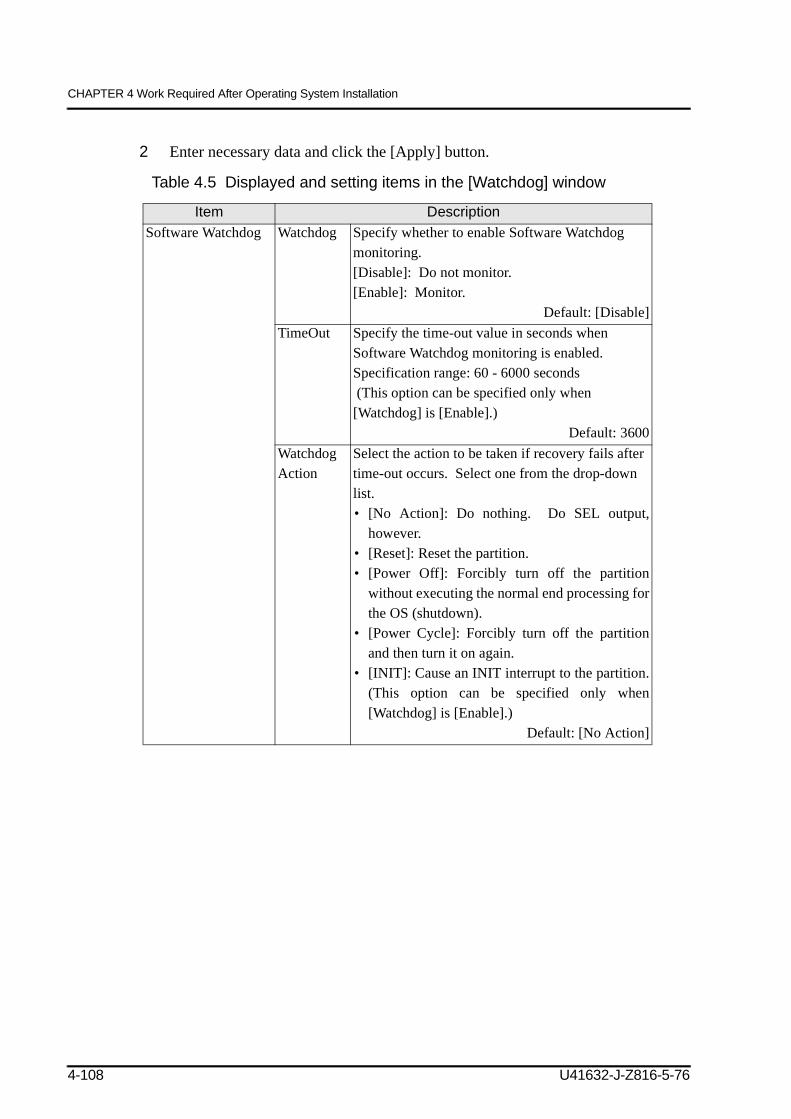
Correction of description for Watchdog setting
U41632-J-Z816-5-76
(2/2)
Edition DateRevised section
(Added/ Deleted/ Altered) (Note)
Details
08 2007-08-31 Section 4.8 (correction) Addition of description for Linux dump function kdump
09 2008-03-10 Entire manual (addition) Addition of description for PRIMEQUEST 580A/540A/520A
10 2008-04-10 Entire manual (correction) Technical brushupFujitsu Technology Solutions issues an additional manual edition in German, adapts text and figures, substitutes the order number of the manual, adds Fujitsu Technology Solutions’ order numbers in manual references, changes the description where the PRIME-QUEST manuals are available, adds footnotes concerning the Fujitsu ser-vice concept REMCS, storage system ETERNUS, service tool FST and the PRIMEQUEST models which are not supported by Fujitsu Technology Solu-tions, substitutes the comment form, and corrects text according to the tables of corrections (errata) 2006/10/10, 2008/09/19, 2008/12/18 and 2009/02/24.
Note:
REMCS and FST are not supported by Fujitsu Technology Solutions.
ETERNUS - supply and support in EMEA for Fujitsu´s global accounts only.
The PRIMEQUEST 520A/540A models are not supported by Fujitsu Technology Solutions.
Note: In this table, the revised section is indicated by its section number in the current edition.An asterisk (*) indicates a section in the previous edition.
U41632-J-Z816-5-76
Preface1
This manual describes the preparation for PRIMEQUEST installation, PRIMEQUEST power-on/off sequences, initialization procedures, and software installation methods. This manual is intended for system administrators.
This section explains
Structure and Contents of this ManualOther Reference ManualsAbbreviationsText ConventionsSyntax of the Command Line Interface (CLI)Notes Regarding Notations Used in This ManualConventions for Alert MessagesEnvironmental Requirements for Using This ProductReader Feedback
Structure and Contents of this ManualThis manual is organized as described below:
CHAPTER 1 PRIMEQUEST OverviewProvides an overview of the hardware, software, and network connections and describes the workflow leading up to the initiation of operation.
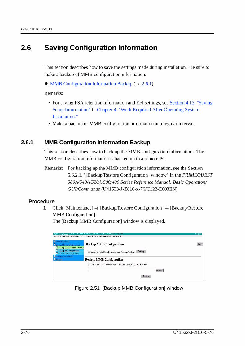
CHAPTER 2 SetupDescribes how to perform the setup procedures required after installing the main unit.
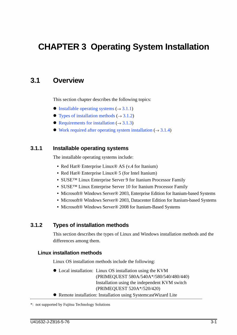
CHAPTER 3 Operating System InstallationDescribes the operating systems that can be installed, types of installation methods, and operating system installation procedures.
CHAPTER 4 Work Required After Operating System InstallationDescribes how to install and set up various software programs after installing the operating system.
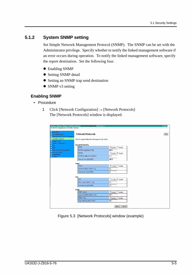
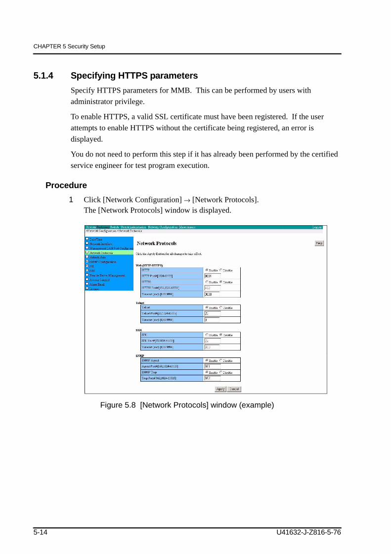
CHAPTER 5 Security SetupDescribes the SNMP and security settings.
U41632-J-Z816-5-76 i
Preface
CHAPTER 6 GSWB InitializationDescribes the initial settings required for using the optional GSWB product.
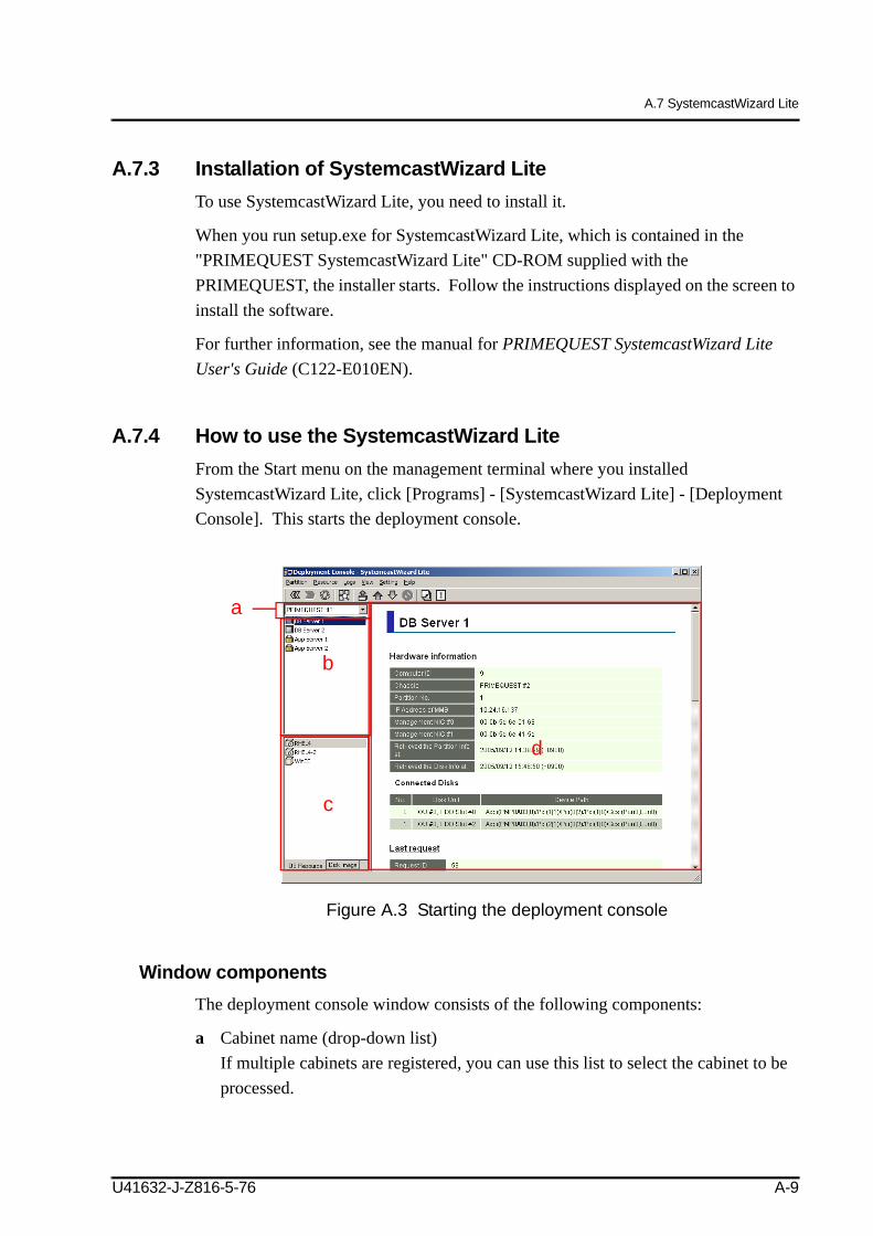
Appendix A Software Programs Supplied with the PRIMEQUEST Hardware
Describes the software programs supplied with PRIMEQUEST.
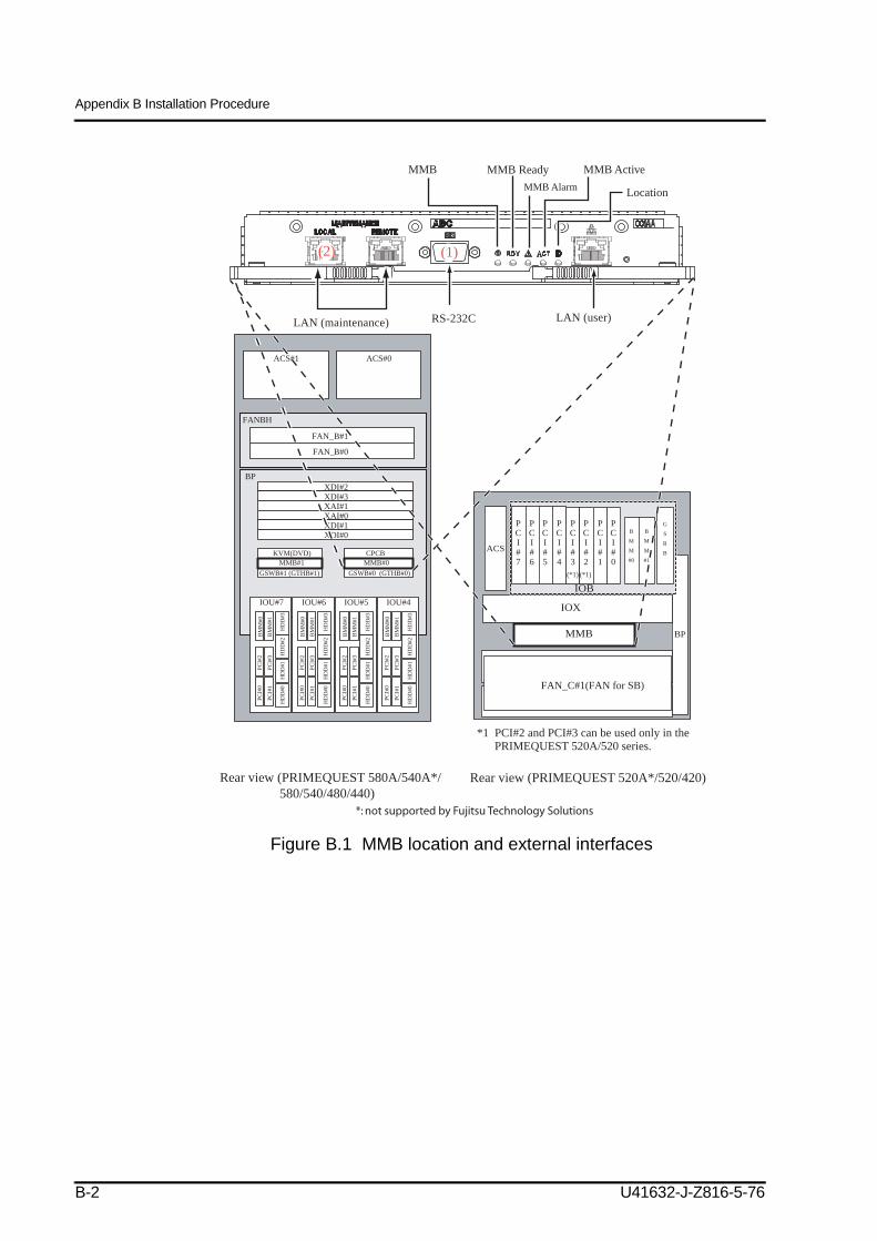
Appendix B Installation ProcedureProvides instructions applicable to PRIMEQUEST installation.
Appendix C Power ControlDescribes power-on and power-off.
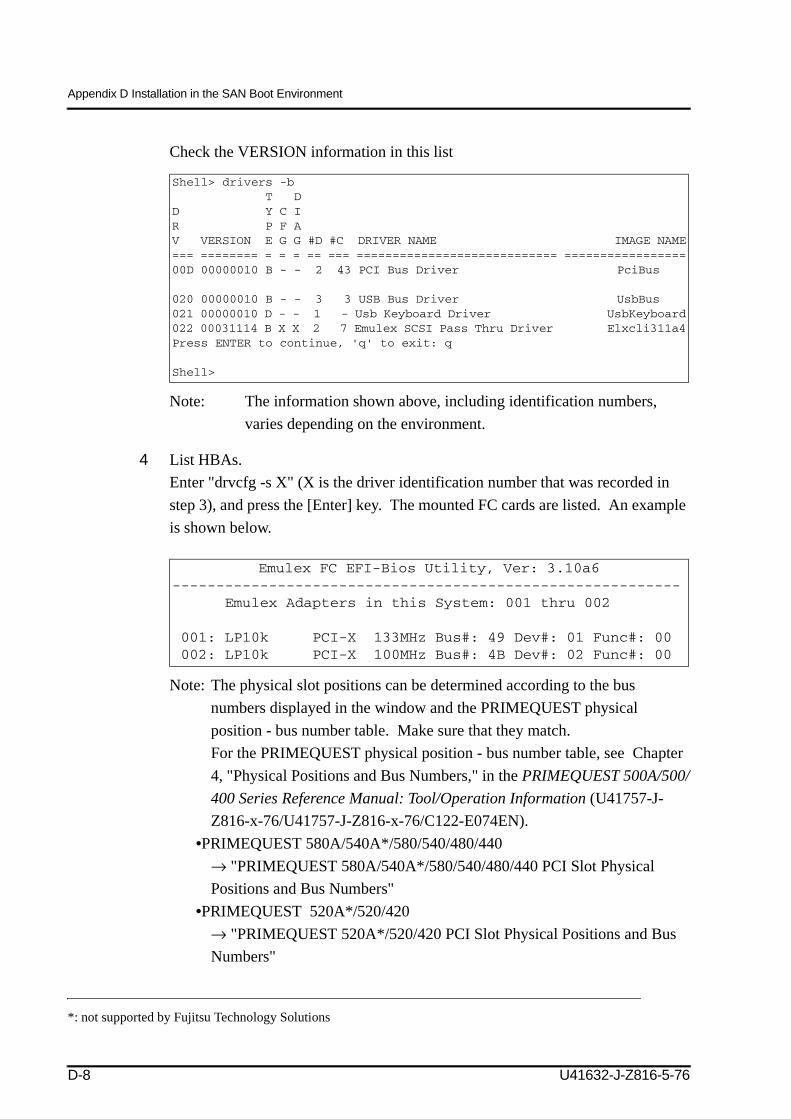
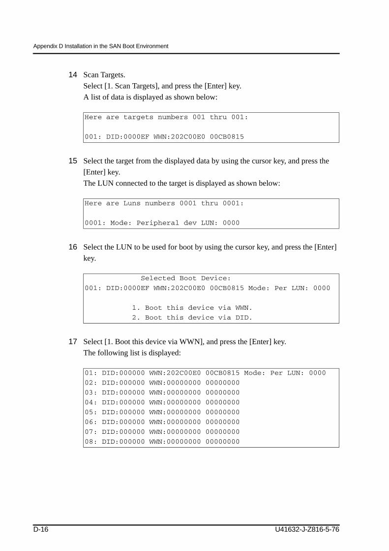
Appendix D Installation in the SAN Boot EnvironmentDescribes how to set up the SAN boot environment.
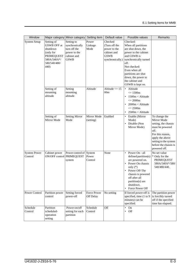
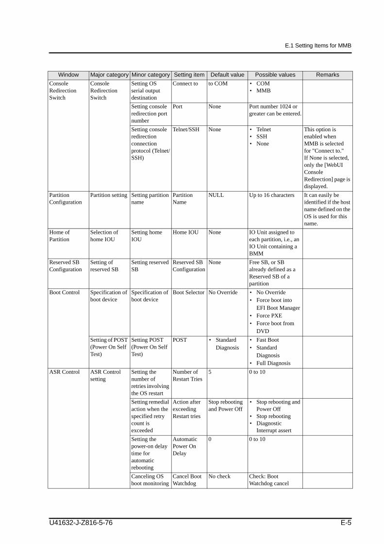
Appendix E Setting Item ListProvides lists of default values for the MMB (server management unit) and PSA (PRIMEQUEST Server Agent).
Appendix F Overall View of Management LAN IP AddressesDescribes the IP addresses used for PRIMEQUEST.
GlossaryExplains the terms used in this manual.
IndexProvides keywords and corresponding reference page numbers so that the reader can easily search for items in this manual as necessary.
ii U41632-J-Z816-5-76
Preface
Other Reference ManualsThe following manuals are available for reference:
a) Supplied printed manual (in German and English also as PDF file available at http://manuals.ts.fujitsu.com/):
b) Manuals available as PDF files at http://manuals.tsfujitsu.com/ (select “Mission Critical IA Server”):
Title Description Manual codePRIMEQUEST 500A/500/400-Series Installation Manual (this manual)
Explains the setup of the PRIMEQUEST, including the preparation for the installation, initial settings, and software installation.
PRIMEQUEST 500A/500/400 Series Reference Manual: Basic Operation/GUI/Commands
Explains operations, setup methods, and the system management method that are required for the system operation of the PRIMEQUEST. The explanation covers basic operations and functions of the MMB, PSA, and EFI.
c) Other manuals, which are available at http://support.ts.fujitsu.com/com/support/downloads.html (select “Mission Critical IA Server” as product)
RH Driver-CD (download “Driver for RHEL4” or “Driver for RHEL5” which contain the manuals):PRIMEQUEST Installation Support Tool User's Guide (Red Hat) (C122-E005EN)PRIMEQUEST 480/440/420 Bundled-Software Package Installer User’s Guide (C122-E006EN)PRIMEQUEST System Parameter Check Tool User's Guide (C122-E009EN)
Suse Driver-CD(download “Driver for SLES9” or “Driver for SLES10” which contain the manuals):PRIMEQUEST Installation Support Tool User's Guide (SUSE) (C122-E047EN)PRIMEQUEST 480/440/420 Bundled-Software Package Installer User’s Guide (C122-E006EN)
SCWL-CD(download “Systemcast Wizard Light CD” which contains the manual):PRIMEQUEST SystemcastWizard Lite User’s Guide (C122-E010EN)
PRIMEQUEST 500A/500/400 Series Reference Manual: Tools/Operation Information
Explains system maintenance, Hot Plug, REMCS*, and LEDs and other information required for system operation. Also, the manual provides supplementary information such as information on the physical locations of components.
PRIMEPOWER Series/PRIMEQUEST Series Common Installation Planning Manual
Explains basic information and policy on installation planning and facilities planning that are required for the installation of the SPARC Enterprise series and PRIMEQUEST series.
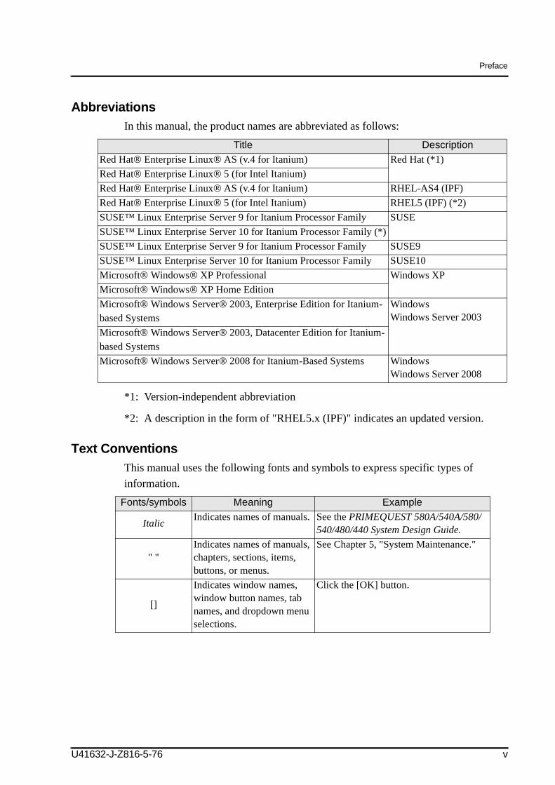
AbbreviationsIn this manual, the product names are abbreviated as follows:
*1: Version-independent abbreviation
*2: A description in the form of "RHEL5.x (IPF)" indicates an updated version.
Text ConventionsThis manual uses the following fonts and symbols to express specific types of information.
Title DescriptionRed Hat® Enterprise Linux® AS (v.4 for Itanium) Red Hat (*1)Red Hat® Enterprise Linux® 5 (for Intel Itanium) Red Hat® Enterprise Linux® AS (v.4 for Itanium) RHEL-AS4 (IPF) Red Hat® Enterprise Linux® 5 (for Intel Itanium) RHEL5 (IPF) (*2)SUSE™ Linux Enterprise Server 9 for Itanium Processor Family SUSESUSE™ Linux Enterprise Server 10 for Itanium Processor Family (*)SUSE™ Linux Enterprise Server 9 for Itanium Processor Family SUSE9SUSE™ Linux Enterprise Server 10 for Itanium Processor Family SUSE10Microsoft® Windows® XP Professional Windows XPMicrosoft® Windows® XP Home EditionMicrosoft® Windows Server® 2003, Enterprise Edition for Itanium-based Systems
WindowsWindows Server 2003
Microsoft® Windows Server® 2003, Datacenter Edition for Itanium-based SystemsMicrosoft® Windows Server® 2008 for Itanium-Based Systems Windows
Windows Server 2008
Fonts/symbols Meaning Example
Italic Indicates names of manuals. See the PRIMEQUEST 580A/540A/580/540/480/440 System Design Guide.
" "Indicates names of manuals, chapters, sections, items, buttons, or menus.
See Chapter 5, "System Maintenance."
[]
Indicates window names, window button names, tab names, and dropdown menu selections.
Click the [OK] button.
U41632-J-Z816-5-76 v
Preface
Syntax of the Command Line Interface (CLI)The command syntax is described below.
Command syntaxThe command syntax is as follows:
A variable that requires input of a value must be enclosed in < >.An optional element must be enclosed in [ ].A group of options for an optional keyword must be enclosed in [ ] and delimited by |.A group of options for a mandatory keyword must be enclosed in { } and delimited by |.
Notes Regarding Notations Used in This ManualItems marked with "Linux" apply to both Red Hat® Enterprise Linux® AS (v.4 for Itanium), Red Hat® Enterprise Linux® 5 (for Intel Itanium) SUSE™ Linux Enterprise Server 9 for Itanium Processor Family, SUSE™ Linux Enterprise Server 10 for Itanium Processor Family.The IO Unit is indicated as "IOU" in the MMB Web-UI and in the figures shown in this manual.
Conventions for Alert MessagesThis manual uses the following conventions to show alert messages. An alert message consists of an alert signal and alert statements.
The command syntax is shown in a frame such as this one.
This indicates a hazardous situation that could result in serious personal injury if the user does not perform the procedure correctly.
This indicates a hazardous situation that could result in minor or moderate personal injury if the user does not perform the procedure correctly. This signal also indicates that damage to the product or other property may occur if the user does not perform the procedure correctly.
This indicates information that could help the user to use the product more effectively.
vi U41632-J-Z816-5-76
Preface
Alert messages in the textIn the text, alert messages are indented to distinguish then from regular text. A wider space precedes and follows the message to show where the message begins and ends.
The important alert messages are listed in the "Important Alert Messages" table in the section titled, "NOTE ON SAFETY." after "Preface."
Environmental Requirements for Using This ProductThis product is a computer which is intended to be used in a computer room. For details on the operational environment, see the following manuals:
Certain tasks in this manual should only be performed by a certified service engineer. Users must not perform these tasks. Incorrect operation of these tasks may cause electric shock, injury, or fire.Installation and reinstallation of all components, and initial settingsRemoval of front, rear, or side coversMounting/de-mounting of optional internal devicesPlugging or unplugging of external interface cardsMaintenance and inspections (repairing, and regular diagnosis and maintenance)
• The Remote Customer Support System (REMCS) is not supported in Europe.• In this manual, it is assumed that two BMMs (optional products) can be connected to a single
IO Unit and IOX; this is reflected both in the explanations and in the figures included in this manual. The PRIMEQUEST 400 series supports only connection to one BMM (BMM#0) per IO Unit and IOX.
• In this manual, the term BP (BackPlane) used in descriptions for the PRIMEQUEST 480/440 series actually stands for MP (MidPlane).
• The screen images in this manual may be different from the actual screen images.• If you find any errors or unclear statements in this manual, please fill in the comment form sheet
at the back of this manual and forward it to the indicated address.• This manual is subject to revision without prior notice.• The PDF version of this manual is best viewed in Adobe® Reader® with a magnification
of 100% and Single Page for the page layout.
U41632-J-Z816-5-76 vii
NOTE ON SAFETY2
Important Alert MessagesThis manual provides the following important alert signals:
This indicates a hazardous situation that could result in minor or moderate personal injury if the user does not perform the procedure correctly. This signal also indicates that damage to the product or other property may occur if the user does not perform the procedure correctly.
Task Warning PageNormal operation
MalfunctionThe MMB Web-UI (Web user interface) supports the following browsers. Note that other browsers may not correctly display the Web UI.Microsoft® IE (Internet Explorer) v5.5 (SP2) or laterNetscape v7.02 or later
P.2-9
Data destructionWhen power to the main processing unit is turned off in an operation from the MMB, only the following LEDs of the OPL and the MMB stay lit:MMB-Ready LED of the OPLPower LED of the MMBReady LED of the MMBActive LED of the MMBBefore turning off the main power (UPS, power distribution box, circuit breaker switches, etc.), be sure to confirm that all LEDs other than the above are off. Otherwise, turning off the main power may cause damage to data.
P.C-6 P.C-8
Data destructionBefore shutting down power, make sure the following events have occurred; otherwise, data may be destroyed:All applications have completed processing.No user is using a component.
P.C-10
viii U41632-J-Z816-5-76
NOTE ON SAFETY
Normal operation
MalfunctionWhen performing the following operations, set Boot Watchdog [Disable]:CD-ROM bootStartup in single user modeBackup and restore using SystemcastWizardIf the operation above is performed with Boot Watchdog set [Enable], operating system restart is repeated for the specified number of times, after which a specified action (Stop rebooting and Power Off, Stop rebooting, or Diagnostic Interrupt assert) is performed. The retry count for restarting the operating system and the action to be performed are determined according to the settings of the [ASR (Automatic Server Restart) Control] window of the MMB.At this time, by clicking the [Apply] button after checking the [Cancel Boot Watchdog] check box in the [ASR (Automatic Server Restart) Control] window of the MMB, Boot Watchdog can forcibly be set to [Disable].
P.4-106Task Warning Page
U41632-J-Z816-5-76 ix
NOTE ON SAFETY
Alert LabelsThe following labels are attached to this product:
These labels provide information to the users of this product.
PRIMEQUEST 580A/540A*/580/540/480/440• Main unit
Do not peel off the labels.
*: not supported by Fujitsu Technology Solutions
x U41632-J-Z816-5-76
NOTE ON SAFETY
• Extended Power Cabinet
U41632-J-Z816-5-76 xi
NOTE ON SAFETY
• Extended I/O Cabinet
xii U41632-J-Z816-5-76
NOTE ON SAFETY
• PCI_Box
PRIMEQUEST 520A*/520/420• Main unit
*: not supported by Fujitsu Technology Solutions
U41632-J-Z816-5-76 xiii
Product Handling3
Maintenance
Remodeling/Rebuilding
Certain tasks in this manual should only be performed by a certified service engineer. Users must not perform these tasks. Incorrect operation of these tasks may cause electric shock, injury, or fire. Installation and reinstallation of all components, and initial settingsRemoval of front, rear, or side coversMounting/de-mounting of optional internal devicesPlugging or unplugging of external interface cardsMaintenance and inspections (repairing, and regular diagnosis and maintenance)
The following tasks regarding this product and the optional products provided from Fujitsu or Fujitsu Technology Solutions should only be performed by a certified service engineer. Users must not perform these tasks. Incorrect operation of these tasks may cause malfunction.Unpacking optional adapters and such packages delivered to the users
Do not make mechanical or electrical modifications to the equipment.Using this product after modifying or overhauling may cause unexpected injury or damage to the property, the user, or bystanders.
2.2.1 Connection environment settings for actual operation . . . . . . . . . . . 2-32.2.1.1 Specifying the IP address for the PC
to be used as the MMB console . . . . . . . . . . . . . . . . . . . . . . 2-42.2.1.2 Connecting the MMB console PC to the MMB user port . . . 2-42.2.1.3 External LAN connection for PRIMEQUEST
(PRIMEQUEST 580A/540A/580/540/480/440) . . . . . . . . . . . 2-52.2.1.4 External LAN connection for PRIMEQUEST
(a configuration characterized by improved reliability) . . . . . . . . . 4-7Figure 4.3 Concept of management LAN duplication in PRIMEQUEST . . . . 4-44Figure 4.4 Concept of management LAN duplication in PRIMEQUEST
(a configuration characterized by improved reliability) . . . . . . . . . 4-45Figure 4.5 Concept of management LAN duplication in PRIMEQUEST . . . . 4-47Figure 4.6 Concept of management LAN duplication in PRIMEQUEST
This section describes the workflow to be executed to start PRIMEQUEST operation.
For the hardware and software overview, see the following manual that applies to your model.
PRIMEQUEST 580A/540A*/580/540/480/440See the PRIMEQUEST 580A/540A/580/540/480/440 System Design Guide (U41630-J-Z816-x-76/C122-B001EN).PRIMEQUEST 520A*/520/420See the PRIMEQUEST 520A/520/420 System Design Guide (U41643-J-Z816-x-76/C122-B009EN).
1.2 Setup Workflow
This chapter describes how to set up the PRIMEQUEST. Some setup tasks should be performed by a certified service engineer, whereas other setup tasks should be performed by the user. This section covers the tasks that should be performed by the user.
*: not supported by Fujitsu Technology Solutions
U41632-J-Z816-5-76 1-1
CHAPTER 1 PRIMEQUEST Overview
Figure 1.1 Setup workflowNotes: Before the user can start setup tasks, certified service engineers must have
executed tasks including machine setup, the part of MMB setup they are responsible for, and test program execution.
Equipment setup Perform inventory checking and BIOS setup and check partitions using a test program.
Testing is conducted in a created test environment.MMB connection (test environment)
Tasks performed by certified service
engineer
Tasks performed by the user
Saving settings
Setup the MMB IP address and other parameters to be used for normal operation and connect to the MMB. See Section 2.2.1.Specify parameters for the entire MMB, such as the user accounts and system name. See Section 2.2.4.
Set the partition names or configure the partition. See Section 2.5.Set up the mode when necessary. See Section 2.5.8.
Save the specified setting values (for MMB and GSWB). See Section 2.6.GSWB is supported only in PRIMEQUEST 580A/540A/580/540/480/440.
GSWB initialization
MMB connection and setup (operating environment)
Network setup for normal operation
MMB initialization
Partition initialization
Mode settings
Install the operating systems. See Chapter 3.
Specify the monitoring method, dump environment, and save the settings (PSA and EFI). See Chapter 4.
Set up the attached software programs. See Appendix A.
Set up SNMP and security.See Chapter 5.
Set up GSWBs when necessary. GSWBs can perform basic functions with as-shipped settings. Basic functions referred to here mean functions that do not use a GSWB VLAN (as shipped, VLANs are not configured). Refer to PRIMEQUEST GSWB User's Manual (U41635-J-Z816-x-76/C122-E028EN). Note: The GSWB is an optional product.
OS installation
Postinstallation work
Setup of attached software programs
Set up
SNMP security setting
* Only for PRIMEQUEST 580A/540A/580/540/480/440
1-2 U41632-J-Z816-5-76
1.2 Setup Workflow
1.2.1 Items required for setupDepending on your system configuration, you have to prepare the following items. If you need to prepare these items, contact the sales personnel or a certified service engineer.
Note: An external switching hub is required to construct a system in a configuration where the PRIMEQUEST is connected to an external switching hub via a LAN.
PC to be used as a console
LAN cables (for user LAN)
U41632-J-Z816-5-76 1-3
CHAPTER 2 Setup1
2.1 Before Starting Setup
The setup procedure roughly consists of steps (1) to (3) below. Before starting setup, you need to determine the address and other information.
If the power has not been supplied to the main unit or partition, turn on the power by performing the power-on procedure explained in Appendix C, "Power Control."
Note: The management LAN and the business LAN must be configured on different subnets.
(1) MMB setup (see Section 2.2 for the procedure)Before starting MMB setup, you need to determine the following:
• IP address, host name, subnet mask, and gateway address• IP address of the PC to be used for the MMB console• User accounts• Name of the PRIMEQUEST system (also used as the SNMP system name)• Environment used for management VLAN
and others.
(2) Partition setup (see Section 2.5 for the procedure)If you use the partition function to configure multiple partitions, you must determine the number of partitions and the following items in advance:
• Partition names• Partition configuration• Home IOU• Boot control• System Mirror
and others.
Note: Naming each partition the same name as the host name of the OS installed in the partition makes managing partition an easier task.
U41632-J-Z816-5-76 2-1
CHAPTER 2 Setup
(3) GSWB setup (only for PRIMEQUEST 580A/540A*/580/540/480/440)(refer to the PRIMEQUEST GSWB User's Manual (U41635-J-Z816-x-76/C122-E028EN))
GSWBs can perform basic functions with as-shipped settings. Basic functions referred to here mean functions that do not use a GSWB VLAN. The PRIMEQUEST GSWB User's Manual (U41635-J-Z816-x-76/C122-E028EN) explains the settings to be made during installation. These settings are not required unless you plan to use GSWB. To make these settings, you must determine the following in advance:
• Host name, host IP address, subnet mask, default gateway• Port to be enabled
Remarks: These settings are required for each GSWB that is used.
*: not supported by Fujitsu Technology Solutions
2-2 U41632-J-Z816-5-76
2.2 MMB Connection and Setup
2.2 MMB Connection and Setup
When you start MMB setup, the MMBs are in a test environment constructed by a certified service engineer, and test programs have been executed in it. Therefore, you need to reset the MMBs for actual operation.
More specifically, you need to specify MMB IP addresses and connect cables assuming actual operation. After the MMBs are connected, use the MMB Web-UI (Web user interface) to register and specify the user accounts, security parameters, time, and other MMB settings.
The figure below shows the MMB connection and setup flow.
2.2.1 Connection environment settings for actual operationThe connection environment for testing must be reset for actual operation. You need to perform the following operations:
Specifying the IP address for the PC to be used as the MMB console (→ 2.2.1.1)Connecting the MMB console PC to the MMB user port (→ 2.2.1.2)External LAN connection for PRIMEQUEST (PRIMEQUEST 580A/540A/580/540/480/440) (→ 2.2.1.3)
Connection environment settings for actual operation → 2.2.1
Network settings for actual operation → 2.2.3
MMB initialization → 2.2.4
Set up the connection environment for actual operation.
Set up the network and Web server to be used for actual operation.
Registration of user accountsSetting user account of certified service engineerSetting system nameSetting date and timeSetting TelnetSetting a VLAN in a administration LAN hub
U41632-J-Z816-5-76 2-3
CHAPTER 2 Setup
2.2.1.1 Specifying the IP address for the PC to be used as the MMB console
On the user's PC to be used as the MMB console, specify the IP address of that PC. For information on the procedure, see the manuals for the PC.
2.2.1.2 Connecting the MMB console PC to the MMB user port
Connect the user's MMB console PC to the MMB user port by using a LAN cable. After connection is complete, the MMB console PC becomes able to communicate with the MMB LAN.
The PRIMEQUEST 580A/540A*/580/540/480/440 uses a redundant MMB configuration in which one MMB is active and the other is a standby. When connecting the cable to an MMB LAN port during the setup, select the port of the active MMB (ACT LED: normally MMB#0 is on) indicated by the LED.
Figure 2.1 Location of the MMB user port
*: not supported by Fujitsu Technology Solutions
* *
2-4 U41632-J-Z816-5-76
2.2 MMB Connection and Setup
Remarks: BMM#1 is supported only in the PRIMEQUEST 500A/500 series.
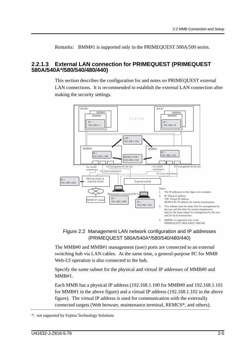
2.2.1.3 External LAN connection for PRIMEQUEST (PRIMEQUEST 580A/540A*/580/540/480/440)
This section describes the configuration for and notes on PRIMEQUEST external LAN connections. It is recommended to establish the external LAN connection after making the security settings.
Figure 2.2 Management LAN network configuration and IP addresses (PRIMEQUEST 580A/540A*/580/540/480/440)
The MMB#0 and MMB#1 management (user) ports are connected to an external switching hub via LAN cables. At the same time, a general-purpose PC for MMB Web-UI operation is also connected to the hub.
Specify the same subnet for the physical and virtual IP addresses of MMB#0 and MMB#1.
Each MMB has a physical IP address (192.168.1.100 for MMB#0 and 192.168.1.101 for MMB#1 in the above figure) and a virtual IP address (192.168.1.102 in the above figure). The virtual IP address is used for communication with the externally connected targets (Web browser, maintenance terminal, REMCS*, and others).
*: not supported by Fujitsu Technology Solutions
BMM#1BMM#1IOU#0
BMM#0 BMM#0
IOU#7
MMB#1
REMCS* center
Dial-up router or external switch
REMOTEREMOTE
External switch
Maintenance terminal (FST*)
IP =192.168.1.201
IP =192.168.1.100
IP =192.168.1.101
IP =192.168.1.200
IP =192.168.3.202
IP =192.168.1.8
IP =192.168.1.1
1.2.
3.
The IP addresses in this figure are examples.
4. BMM#1 is supported only in the PRIMEQUEST 580A/540A*/580/540.
IP: Physical addressVIP: Virtual IP addressREMCS IP: IP address for remote maintenance.
Two subnets must be setup: One for management bythe user and the other for remote maintenance.Specify the same subnet for management by the userand for local maintenance.
MMB#0
REMOTEREMOTE
Web-UIWeb-UI
VIP =192.168.1.102
REMCS VIP =192.168.3.102
Notes:
For remote maintenance
For remote maintenance
For local maintenanceFor local maintenance
For management by the user For management by the user
U41632-J-Z816-5-76 2-5
CHAPTER 2 Setup
Note:
If you want to use a switching hub that supports a loop guard function (such as the spanning tree protocol and domain separation) as an external switch, suppress the loop guard function by disabling [Spanning Tree Protocol] for the port for connection between the switching hub and the main unit or by turning on [Domain Separation].
The MMB transmits packets in communication of the following types: NTP, alarm e-mail, REMCS*, and SNMP trap. If both a physical IP address and a virtual address are set for the MMB, the IP address of the packet sender becomes the physical IP address of the MMB.Under the following conditions, firewall, mail, and other servers must be configured such that the packets with the physical IP addresses of MMB#0 and MMB#1 can pass through:
- The destination server is an external server outside the firewall.
- IP addresses are restricted by the mail server used.
Also, if the REMOTE MAINTENANCE port is used with the PRIMEQUEST 580A/540A* under the above conditions, the servers must be configured such that the packets with the IP addresses for REMOTE MAINTENANCE can pass through.
Remarks:
The physical IP addresses of the MMBs are also used for linkage with PRIMECLUSTER.
If REMCS* connection is involved, the connection method explained below is used. For details, see Chapter 6, "REMCS" in the PRIMEQUEST 80A/540A/520A/580A/540A/520A/500/400 Series Reference Manual: Basic Operation/GUI/Commands (U41633-J-Z816-x-76/C122-E003EN).
- Internet connection:The REMCS ports are connected to an external switching hub or to the center via the firewall from the external switch of the management port.
- P-P connection:The REMCS port of each MMB (MMB#0 and MMB#1) is directly connected to the dial-up router.
*: not supported by Fujitsu Technology Solutions
2-6 U41632-J-Z816-5-76
2.2 MMB Connection and Setup
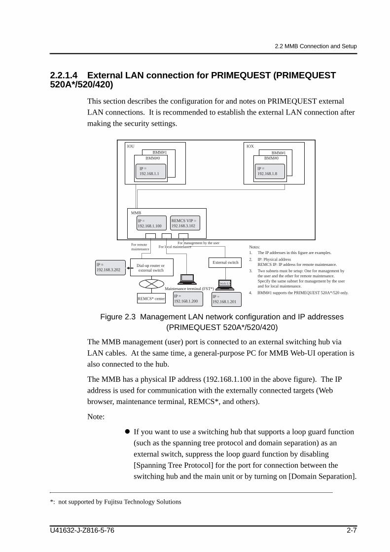
2.2.1.4 External LAN connection for PRIMEQUEST (PRIMEQUEST 520A*/520/420)
This section describes the configuration for and notes on PRIMEQUEST external LAN connections. It is recommended to establish the external LAN connection after making the security settings.
Figure 2.3 Management LAN network configuration and IP addresses (PRIMEQUEST 520A*/520/420)
The MMB management (user) port is connected to an external switching hub via LAN cables. At the same time, a general-purpose PC for MMB Web-UI operation is also connected to the hub.
The MMB has a physical IP address (192.168.1.100 in the above figure). The IP address is used for communication with the externally connected targets (Web browser, maintenance terminal, REMCS*, and others).
Note:
If you want to use a switching hub that supports a loop guard function (such as the spanning tree protocol and domain separation) as an external switch, suppress the loop guard function by disabling [Spanning Tree Protocol] for the port for connection between the switching hub and the main unit or by turning on [Domain Separation].
*: not supported by Fujitsu Technology Solutions
BMM#1BMM#1IOU
BMM#0 BMM#0
IOX
REMCS* center
Dial-up router or external switch
REMOTEREMOTE
External switch
Maintenance terminal (FST*)
IP =192.168.1.201
IP =192.168.1.100
IP =192.168.1.200
IP =192.168.3.202
IP =192.168.1.8
IP =192.168.1.1
MMB
For remote maintenance
Web-UIWeb-UI
For local maintenanceFor local maintenanceFor local maintenanceFor management by the userFor management by the userFor management by the user
REMCS VIP =192.168.3.102
1.2.
3.
The IP addresses in this figure are examples.
4. BMM#1 supports the PRIMEQUEST 520A*/520 only.
IP: Physical addressREMCS IP: IP address for remote maintenance.Two subnets must be setup: One for management bythe user and the other for remote maintenance.Specify the same subnet for management by the userand for local maintenance.
Notes:
U41632-J-Z816-5-76 2-7
CHAPTER 2 Setup
The MMB transmits packets in communication of the following types: NTP, alarm e-mail, REMCS*, and SNMP trap.Under the following conditions, firewall, mail, and other servers must be configured such that the packets with the physical IP address of MMB can pass through:
- The destination server is an external server outside the firewall.
- IP addresses are restricted by the mail server used.
Also, if the REMOTE MAINTENANCE port is used with the PRIMEQUEST 520A* under the above conditions, the servers must be configured such that the packets with the IP addresses for REMOTE MAINTENANCE can pass through.
Remarks:
The IP addresses of the MMB are also used for linkage with PRIMECLUSTER.
If REMCS* connection is involved, the connection method explained below is used. For details, see Chapter 6, "REMCS" in the PRIMEQUEST 580A/540A/520A/500/400 Series Reference Manual: Basic Operation/GUI/Commands (U41633-J-Z816-x-76/C122-E003EN).
- Internet connection:The REMCS* ports are connected to an external switching hub or to the center via the firewall from the external switch of the management port.
- P-P connection:The REMCS* port of MMB is directly connected to the dial-up router.
2.2.2 MMB login and logout, and window configurationYou use the MMB Web-UI window for operations in Section 2.2.3, "Network settings for actual operation," 2.2.4, "MMB initialization", and 2.5, "Partition Initialization." This section explains how to log in to MMB Web-UI and how to read its display.
Login to and logout from the MMB Web-UI (→ 2.2.2.1)Web-UI window elements (→ 2.2.2.2)
*: not supported by Fujitsu Technology Solutions
2-8 U41632-J-Z816-5-76
2.2 MMB Connection and Setup
2.2.2.1 Login to and logout from the MMB Web-UI
The procedure for logging in to the MMB Web-UI is described below.
To log in to the Web-UI, you need to either specify the virtual IP address or physical IP address of the active MMB, or specify the fully qualified domain name (FQDN) corresponding to the IP address.
To specify a fully qualified domain name (FQDN), the DNS server must already be specified.
Login procedure1 Start the Web browser.
Remarks 1: To use JavaScript, the MMB Web-UI must enable it by browser setting.
Remarks 2: For downloading through the MMB Web-UI, downloading must be enabled by the browser setting.
2 Enter the following URL.
nodename: Specifies an MMB FQDN or IP address.adminport: Specifies a port number that is allocated to the MMB management
port (default value: 8081 for standard or 432 for SSL).3 Enter a user account name and password as follows, and click the [Login] button.
Remarks: When the browser is started for the first time or a setting change is not made, the following default user account and password are applied and a change to a new password is requested.
MalfunctionThe MMB Web-UI (Web user interface) supports the following browsers. Note that other browsers may not correctly display the Web UI.Microsoft® IE (Internet Explorer) v5.5 (SP2) or laterNetscape v7.02 or later
Standard http://nodename:adminportSSL https://nodename:adminport
Username AdministratorPassword Password specified by a certified service
engineer during system setup.
U41632-J-Z816-5-76 2-9
CHAPTER 2 Setup
Logout procedure1 To quit operation, click [Logout] on the upper right of the browser window.
Log out from the Web-UI.Remarks: To perform other operations, select a menu or sub-menu.
2.2.2.2 Web-UI window elements
This section explains information to be displayed on the Web-UI window using the window of the PRIMEQUEST 580A/540A*/580/540/480/440 as an example.
Information displayed on the window
Figure 2.4 [Web-UI Frame Information] Window
a) Llogo displayThe Fujitsu logo mark is displayed. Click this mark to display Fujitsu Technology Solutions´ homepage.
b) Information area
This area displays the following information.
*: not supported by Fujitsu Technology Solutions
a) Logo display b) Information area c) Active MMB display
d) Maintenance status display
e) Navigation bar
g) Sub-menu hierarchy display bar
h) Content display area
f) Sub-menu
2-10 U41632-J-Z816-5-76
2.2 MMB Connection and Setup
[Model]Displays the PRIMEQUEST model name (Product Info Product Name of operation panel FRU).[Part Number]Displays the PRIMEQUEST part number (Product Info Product Part/Model Number of operation panel FRU).
Note: When "Read Error" is displayed, contact a certified service engineer.
[Serial Number]Displays the serial number of the PRIMEQUEST.
Note: When "Read Error" is displayed, contact a certified service engineer.
[Status]Displays the status of the entire PRIMEQUEST. The system status display indicates the three statuses below. Click one of the three to display the [System Event Log] window.
Table 2.1 System status display
c) Active MMB displayDisplays the number of the MMB that is operating as an active MMB with the Web-UI connected.
d) Maintenance status displayWhen a certified service engineer is maintaining this device by using a maintenance wizard menu, "Under Maintenance" is displayed in orange. When maintenance is not being conducted, no information is displayed.
e) Navigation bar
The top layer menus are displayed. A menu being selected is displayed in black characters, and one not selected is displayed in white characters.
Status Display color IconNormal Green None
Warning YellowBlack ! in yellow triangle
Error Red White x in red circle
U41632-J-Z816-5-76 2-11
CHAPTER 2 Setup
[System], [Partition], [Switch], [User Administration], [Network Configuration], [Maintenance]Click one of the menus to display the sub-menu in g).
Note: [Switch] is displayed for the PRIMEQUEST 520A*/520/420 and for the PRIMEQUEST 580A/540A*/580/540/480/440 with a built-in GTHB.
[Logout]Click here to log out from the MMB Web-UI.
f) Sub-menu hierarchy display bar
Hierarchy displayThe menu hierarchies that the user passes from the top menu to the sub-menu displayed in the sub-menu area are displayed. Click the menu displayed here to display the content window of that menu.
g) Sub-menuThe sub-menu of the menu selected on the navigation bar is displayed.
*: not supported by Fujitsu Technology Solutions
Example: >System>System Status
2-12 U41632-J-Z816-5-76
2.2 MMB Connection and Setup
Figure 2.5 Sub-menu
The sub-menu is displayed as follows.
• Up to three menu hierarchies are displayed.• A "+" display at the beginning indicates that there are lower-layer
menus. • A "-" display at the beginning indicates that there are lower layer
menus, which are expanded.• A "-" display at the beginning indicates that there is no lower menu.• When the cursor is positioned on a menu, the menu color is
displayed in reverse video.• The background color of a selected menu changes.
U41632-J-Z816-5-76 2-13
CHAPTER 2 Setup
h) Content areaThe window for a selected sub-menu is displayed in the content area.
Figure 2.6 Content area
The content area is divided into the following three.
Title areaContent title is displayed.
• This area has a [Help] button for displaying the Help menu for the content and the [Refresh] button to display the most up-to-date content.
• The [Refresh] button is applied to only the content area.• The [Refresh] button is not displayed on all windows. It is not displayed on one
where only settings are made and its status is not automatically changed.
Remarks:Use [Refresh Rate] in the [Network Configuration] menu to set a refresh rate.
• Windows with a [Refresh] button display are subject to automatic refreshing. (Excluding PSA)
• This area is not scrolled together with [Status display and setting area].
Status display and setting area
This area displays content related status and setting details.The status display has three patterns, "Normal status," "Warning status," and "Error status," each displayed with the background colors indicated below.
2-14 U41632-J-Z816-5-76
2.2 MMB Connection and Setup
Table 2.2 Status display
When the user has only the display authority, input field, radio button, and check box are displayed dimmed (not selectable).
Button areaButtons for setting the status display and setting the setting area contents are displayed. The [Apply] and [Cancel] buttons are normally displayed.For contents that are displayed only and do not require user input, this button area is not displayed.
Basic operationThe basic operation flow is as follows:
1 Select a menu from the navigation bar.The submenu of the selected menu is displayed in the sub-menu area.
2 Select a menu from the sub-menu.The window of the selected menu is displayed in the content area.
3 Check and set information on the displayed window.Click the [Apply] button to set the information.Click the [Cancel] button to return the information to its state before it was input.Remarks: To return to the upper hierarchy, click the [←] (Back) button on the
IE toolbar.The upper-hierarchy screen is displayed in the content area.
Note: If the MMB Web-UI is used from Internet Explorer and the dialog box for process execution confirmation or process completion notification is displayed for more than two minutes, the MMB Web-UI is disconnected. In such cases, log in to the MMB Web-UI again.
Status Background colorNormal Typical window background color Warning Warning color (yellow)Error Error color (red)
U41632-J-Z816-5-76 2-15
CHAPTER 2 Setup
Notation used for window operationThe window operations in this manual are described as follows:
Menu operation of Web UI[ ] → [ ]Example: Describing the operation procedure for displaying the [System Status]
windowClick [System] → [System Status]. (Select the items in order of indication.)
Describing multiple menus indicated in the same hierarchy[ ]/[ ]/[ ]/[ ]Example: Describing the operation procedure for displaying the [Port
Configuration] window of the IOU, front panel, port-channel, or partitionClick [Switch] → [GSWB#x] → [Port] → [Port Configuration] → [IOU]/[Front Panel]/[port-channel]/[Partition].
Describing one of multiple components (The actual Web-UI is indicated with a number.)Component-name#xExample: Describing a partition number in the second hierarchy
Click [Partition] → [Partition#x] → [Mode].
If one of the MMB error or warning states shown in the following "operation interruption check conditions" occurs, refrain from operating the window. Instead, contact a certified service engineer.
Operation interruption check conditions• The Alarm LED on the MMB is on.• The Active LEDs on both MMB#0 and MMB#1 are off.• A connection to the MMB Web-UI cannot be established.• The Alarm LEDs on two or more boards in the main unit are on.• "ReadError" is displayed on the MMB Web-UI.• "Not Present" is displayed for the state of every unit in the [System Status]
window of the MMB Web-UI.
2-16 U41632-J-Z816-5-76
2.2 MMB Connection and Setup
2.2.3 Network settings for actual operationThis section explains the following settings, which are required for actual operation. Perform these as needed for your operation mode.
Setting up the MMB network (PRIMEQUEST 580A/540A*/580/540/480/440) (→ 2.2.3.1)Setting up the MMB network (PRIMEQUEST 520A/520/420) (→ 2.2.3.2)Specifying Telnet parameters (→ 2.2.3.3)Setting up the DNS server (→ 2.2.3.4)
For backing up the settings, see Section 2.6, "Saving Configuration Information."
Remarks: This can be performed by users with administrator privilege.
2.2.3.1 Setting up the MMB network (PRIMEQUEST 580A/540A*/580/540/480/440)
Specify information including the virtual IP address used to access the Web-UI and the physical IP address assigned to the MMB interface.
Note that this information may have already been set by a certified service engineer. If the information need not be changed, proceed with the next setting.
Notes:
Specify the same subnet for the physical and virtual IP addresses of MMB#0 and MMB#1.
When the virtual IP address is set, and the PRIMEQUEST series machine is accessed from an external device (for example, from a Web browser, maintenance terminal, the REMCS*, etc.), the access is performed through the virtual IP address. Therefore, it is impossible to access the MMB Web-UI by specifying the physical IP address of MMB #0 or MMB #1.
Remarks:
If you make changes to [MMB#0 IP Address] or [MMB#1 IP Address] and click the [Apply] button in the [Network Interface] window, the network is temporarily stopped and the Web-UI is disconnected to reflect the settings. In this case, you can reconnect the Web-UI by making a selection from the menu.
When the IP address is changed, the connection to the MMB Web-UI is terminated. To use the MMB Web-UI, log in again.
2 Specify the IP Address, Subnet Mask, and Gateway Address to the [Virtual IP Address] items. The host name must be specified.
Table 2.3 Displayed and setting items in the [Network Interface] window
3 In [MMB#0 IP Address] or [MMB#1 IP Address], click [Enable] for the [Interface] item, and enter values for each item.Specify the physical IP address to be assigned.
*: not supported by Fujitsu Technology Solutions
Item DescriptionHostname Specify the host name.IP Address Specify the virtual IP address to be used to access the Web-UI.Subnet Mask Specify the subnet mask.Gateway Address Specify the gateway IP address.
2-18 U41632-J-Z816-5-76
2.2 MMB Connection and Setup
Table 2.4 Displayed and setting items in the [Network Interface] window
4 After setting all necessary items, click the [Apply] button.Note: If an incorrect value is specified for the IP address or another required
parameter, the MMB Web-UI is not displayed. Connect a general-purpose PC to the COM port of the MMB, and specify the correct values.For details on how to set the parameters, see Appendix B, "Installation Procedure."
2.2.3.2 Setting up the MMB network (PRIMEQUEST 520A*/520/420)
Specify information including the IP address used to access the Web-UI.
Note that this information may have already been set by a certified service engineer. If the information need not be changed, proceed with the next setting.
Remarks: When the IP address is changed, the connection to the MMB Web-UI is terminated. To use the MMB Web-UI, log in again.
Item DescriptionHostname Specify the host name.IP Address Specify the IP address.Subnet Mask Specify the subnet mask.Gateway Address Specify the gateway IP address.
*: not supported by Fujitsu Technology Solutions
U41632-J-Z816-5-76 2-19
CHAPTER 2 Setup
2 Specify the IP Address, Subnet Mask, and Gateway Address to the [IP Address] items. The host name must be specified.
Table 2.5 Displayed and setting items in the [Network Interface] window
3 After setting all necessary items, click the [Apply] button.Note: If an incorrect value is specified for the IP address or another required
parameter, the MMB Web-UI is not displayed. Connect a general-purpose PC to the COM port of the MMB, and specify the correct values.For details on how to set the parameters, see Appendix B, "Installation Procedure."
Item DescriptionHostname Specify the host name.IP Address Specify the IP address to be used to access the Web-UI.Subnet Mask Specify the subnet mask.Gateway Address Specify the gateway IP address.
2-20 U41632-J-Z816-5-76
2.2 MMB Connection and Setup
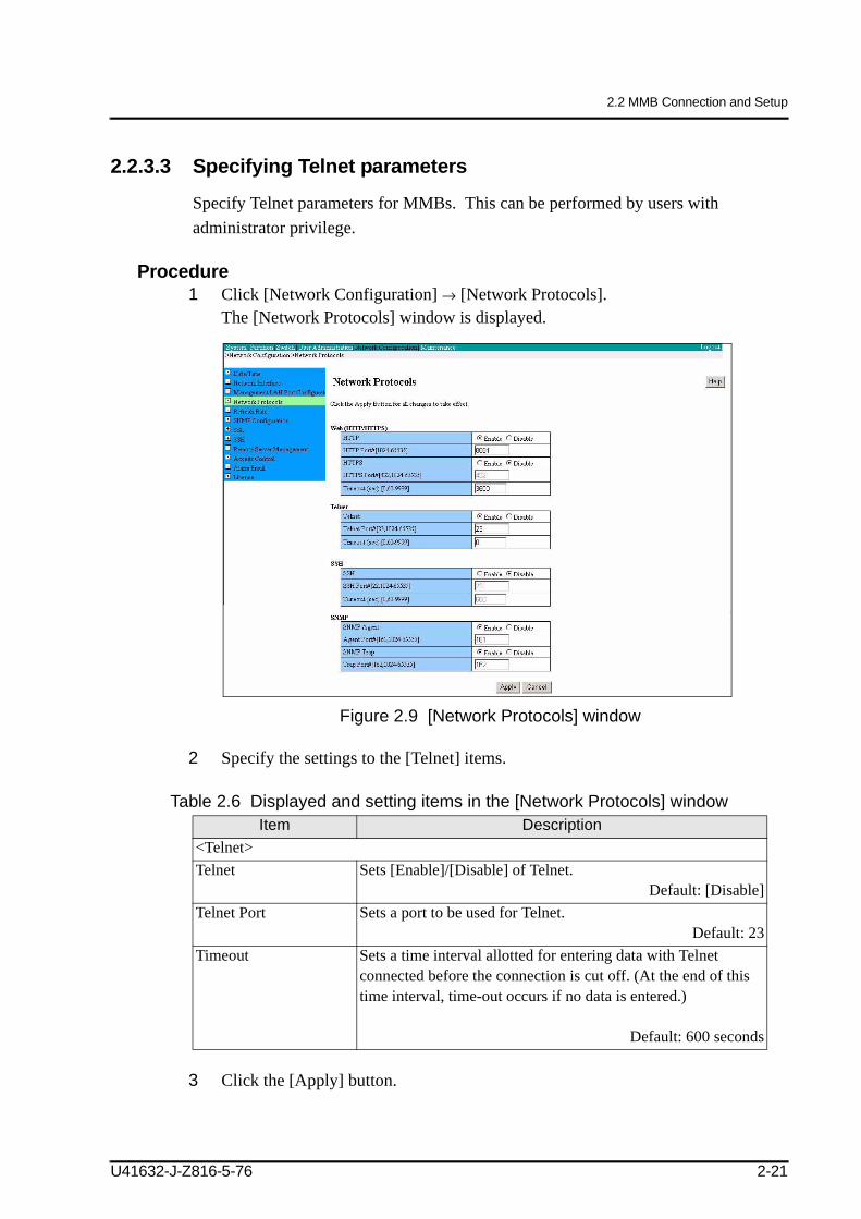
2.2.3.3 Specifying Telnet parameters
Specify Telnet parameters for MMBs. This can be performed by users with administrator privilege.
2 Click [Enable] for the [DNS] item under [DNS (optional)], and enter values for each item.
Table 2.7 Displayed and setting items in the [Network Interface] window
3 After all necessary settings have been made, click the [Apply] button.
2.2.3.5 SMTP settings
Set up MMB SMTP (Simple Mail Transfer Protocol). More specifically, specify whether to report errors by e-mail if they occur during operation. If you specify reporting by e-mail, you will also need to specify the error level and the report destinations.
*: not supported by Fujitsu Technology Solutions
Item DescriptionDNS Specify whether to use the DNS server.
Enabled: Use the DNS server.Disabled: Do not use the DNS server.The default is [Disabled].
DNS Server1 Specify the IP address of DNS server 1.DNS Server2 Specify the IP address of DNS server 2.DNS Server3 Specify the IP address of DNS server 3.
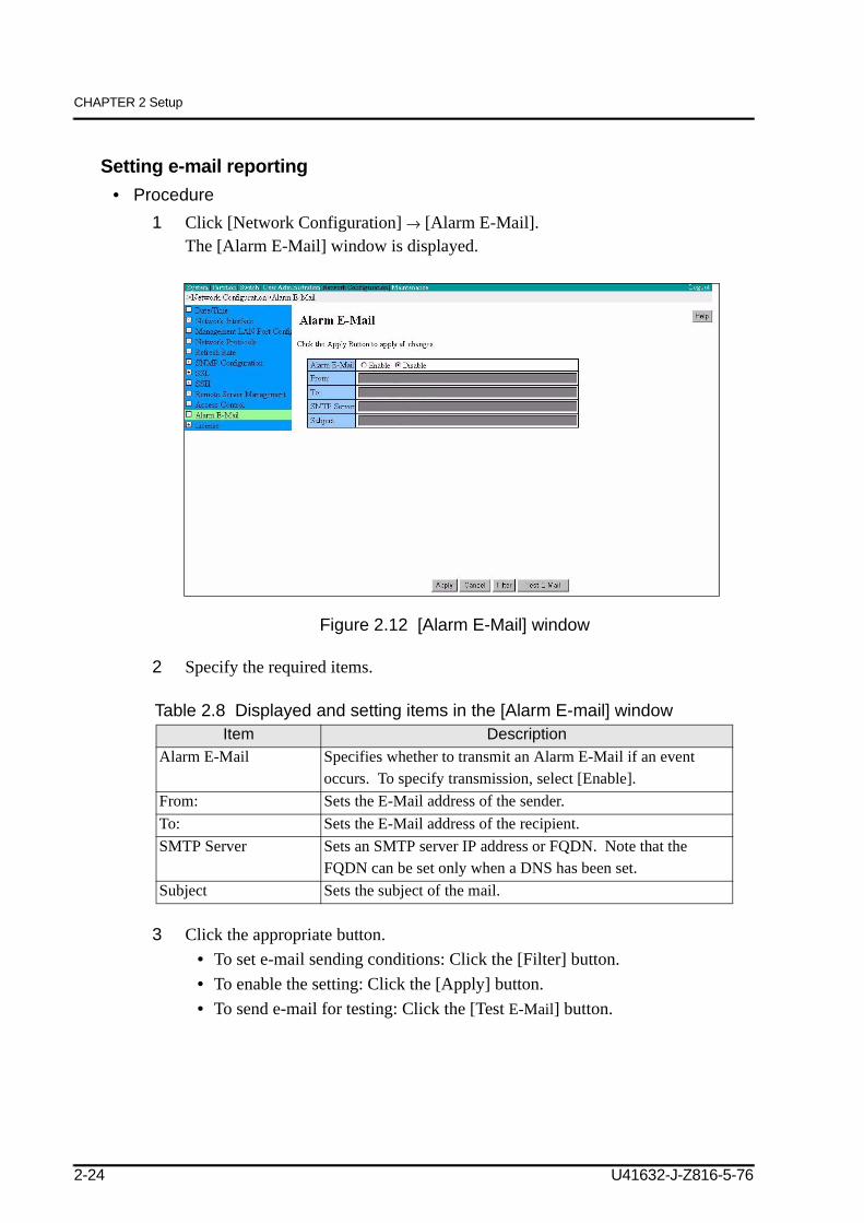
Table 2.8 Displayed and setting items in the [Alarm E-mail] window
3 Click the appropriate button.• To set e-mail sending conditions: Click the [Filter] button.• To enable the setting: Click the [Apply] button.• To send e-mail for testing: Click the [Test E-Mail] button.
Item DescriptionAlarm E-Mail Specifies whether to transmit an Alarm E-Mail if an event
occurs. To specify transmission, select [Enable]. From: Sets the E-Mail address of the sender. To: Sets the E-Mail address of the recipient. SMTP Server Sets an SMTP server IP address or FQDN. Note that the
FQDN can be set only when a DNS has been set.Subject Sets the subject of the mail.
2-24 U41632-J-Z816-5-76
2.2 MMB Connection and Setup
[start of correction according to the manual errata 2008/12/18]
Note: A DNS server must be specified prior to specifying a fully qualified domain name (FQDN). You can specify it by selecting [Network Configuration] → [Network Interface].
Note: - The From address for sending mail to the SMTP server when Alarm E-Mail is sent is as follows depending on the format set from [Network Configuration] ¨ [Network Interface]: FQDN format root@[Hostname] Other than FQDN format root@[Hostname].[Hostname] The mail address that is set in From is used as the From address for sending mail to the receiving (To) address.
- To specify an FQDN for the SMTP Server name, the DNS server must already be set. The DNS server can be set by selecting [Network Configuration] ¨ [Network Interface].
[end of correction according to the manual errata 2008/12/18]
U41632-J-Z816-5-76 2-25
CHAPTER 2 Setup
Specifying mail sending conditions• Procedure
1 To specify mail sending conditions, click the [Filter] button in the [Alarm E-Mail] window.The [Alarm E-Mail Filtering Condition] window is displayed.
2 Select the required items.If multiple items are selected, they are joined by the AND operator and their sub-items are joined by the OR operator.
Table 2.9 Displayed and setting items in the [Alarm E-mail Filtering Condition] window
3 Click the [Apply] button.
Item DescriptionSeverity Selects the level of Severity to be reported by e-mail. More than one can be
selected. • [Error]: Important problems such as hardware problems• [Warning]: Events not always important but likely be a problem in the
future• [Info]: Normal events such as partition power-on
Default: All errorsPartition Selects the target partition for reporting by mail. More than one can be
selected. Default: All partitions
Unit Selects a unit to be displayed.Select [All] or [Specified] with a radio button.• If [All] is selected, filtering by [Unit] is not done. • If [Specified] is selected, filtering by unit can be set. Use the check box
to select a unit for which you want events displayed.Default: [All]
Source Selects the source on which notification e-mail is to be sent.Select [All] or [Specified] with a radio button.• [All]: Filtering by source is not done.• [Specified]: Filtering by source can be set.
U41632-J-Z816-5-76 2-27
CHAPTER 2 Setup
2.2.4 MMB initializationThis section explains the operations for various types of MMB initialization.
Note: The MMB uses the following TCP/IP port numbers:- 623/udp: RMCP communication- 664/udp: RMCP communication- 5000: Event communication from PSA
It is recommended to back up the setup information after completing the following setup tasks.
For backing up the settings made here, see Section 2.6, "Saving Configuration Information."
Registering user accounts (→ 2.2.4.1)Specifying a user account for the certified service engineer in charge (→ 2.2.4.2)Specifying the system name (→ 2.2.4.3)Setting the date and time (→ 2.2.4.4)Setting a management LAN hub (→ 2.2.4.5)
Table 2.10 Displayed and setting items in the [User List] windowItem Description
User name Displays the user name.Full Name Displays the actual name of [User Name].Privilege Displays permission for the user account.Status Displays the current status of this account:
Enabled or Disabled.
U41632-J-Z816-5-76 2-29
CHAPTER 2 Setup
2 Click the [Add User] button.The [Add User] window appears.
Figure 2.16 [Add User] window
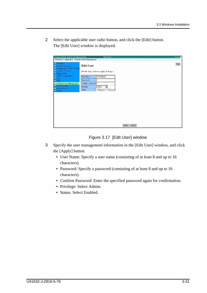
Note: To change an existing user account, click the [Edit User] button in the [User List] window, and change its registration details in the [Edit User] window.
3 Specify the required items.
Table 2.11 Displayed and setting items in the [Add User] windowItem Description
User name
Specify the user name, using 8 to 32 characters.The characters that can be used to specify the user name are 0 to 9, a to z, A to Z, -, and _.The user name must begin with a letter from a to z or A to Z.
Password
Specify the password in 8 to 32 characters. The password cannot be one that can be easily guessed by the help of dictionary. If the specified password is inappropriate, the system prompts for another password.The characters that can be used to specify the password are as follows:Digits: 0 to 9Letters: a to z, A to ZSpecial characters: ! " # $ % & ' ( ) = - ^ ~ \ @ `[ ] { } : * ; + ? < . > , / _ |
Confirm Password Reenter the password for confirmation.
2-30 U41632-J-Z816-5-76
2.2 MMB Connection and Setup
4 Click the [Apply] button.
Privilege
Specify permission for the user account.
[User]
The user account is permitted only to read the PRIMEQUEST system status.The user account is not permitted to specify system configuration information or to turn on/off the power to the partition.
[CE]
The user account is permitted to read the PRIMEQUEST system status.It is not permitted to perform user management or network configuration change operation or to turn on/off the power to the partition or the system using the normal procedure.Maintenance operations are permitted.
[Operator]
The user account is permitted to read and specify the PRIMEQUEST system status. However, it is not permitted to perform user management or LAN configuration change operation.
[Admin]The user account is permitted to perform any operation.Note: [Admin] means administrator privilege.
StatusSpecify the current status of this account.• [Enabled]: The account is available.• [Disabled]: The account is not available.
Full NameUsed to enter the actual name corresponding to the name specified for [User Name] or other information. This field accepts up to 32 characters.
Item Description
U41632-J-Z816-5-76 2-31
CHAPTER 2 Setup
2.2.4.2 Specifying a user account for the certified service engineer in charge
Specify a user account that will be used by the certified service engineer in charge for maintenance purposes. The procedure is the same as that described in Section 2.2.4.1, "Registering user accounts." Specify the user permission for the certified service engineer as CE.
2.2.4.3 Specifying the system name
Specify a name for the PRIMEQUEST system. Only users who are granted Admin permission can change this name. This name is also used as the SNMP system name.
Procedure1 Click [System] → [System Information].
The [System Information] window appears.
Figure 2.17 [System Information] window
2-32 U41632-J-Z816-5-76
2.2 MMB Connection and Setup
2 Specify [System Name].
Table 2.12 Displayed and setting items in the [System Information] window
3 Click the [Apply] button.
Item DescriptionSystem Name The name assigned to the PRIMEQUEST system is displayed.
Users who are granted Admin permission can change this name. This field accepts up to 64 characters.
Default: PRIMEQUEST + serial numberRemarks:• Any of the following characters can be used:
[0-9],[a-z],[A-Z], (en-size space) ! " # $ % & ' ( ) = - ^ ~ \ @ ` [ ] { } : * ; + ? < . > , / _ |However, the following restrictions apply:- The following characters cannot be used at the beginning
of a string:# (en-size space)
- The following character cannot be used at the end of the string: (en-size space)
• This name will also be used as the SNMP system name.SNMP system name specification cannot be performedseparately. The system name specified here is displayed onthe [SNMP Configuration] window and it cannot bechanged.
Product Name The product name of the PRIMEQUEST system is displayed.Part Number The part number of the PRIMEQUEST system is displayed.
Note: When "Read Error" is displayed, contact your a certified service engineer.
Serial Number The serial number of the PRIMEQUEST system is displayed.Note: When "Read Error" is displayed, contact your a certified
service engineer.FSB Frequency The frequency is displayed.Asset Tag Asset management information is displayed.
Users who are granted Administrator permission can change the Asset Tag information. This field can accommodate up to 32 characters.Remarks:This field is designed for users to manage the PRIMEQUEST system asset number and others.
U41632-J-Z816-5-76 2-33
CHAPTER 2 Setup
2.2.4.4 Setting the date and time
Set the MMB date and time and NTP (when the NTP server is used).
You do not need to perform this step if it has already been performed by the certified service engineer for test program execution.
Remarks: The MMB has NTP client and NTP server functions. The NTP client function of the MMB makes time adjustments using the other NTP server. Each PRIMEQUEST partition uses the NTP server function of the MMB to adjust the time in a partition.However, the MMB need not be specified for the NTP servers in any of the partitions. For stable NTP operation, specify multiple NTP servers from the NTP client (at least three are recommended).
Table 2.13 Displayed and setting items in the [Date/Time] window
3 Click the [Apply] button.
Item DescriptionDate Specifies a date.
* No setting is required if an NTP server is used.Time Sets hh:mm:ss (24-hour format). To set the time, select the
[Modify the Time] check box. Entry in the hh:mm:ss time field is enabled only when the check box is selected.Because the MMB time when this window is opened is displayed, reloading is required to update the display.When the automatic update is set, the time when the window is updated is displayed.* No setting is required if an NTP server is used.
Time zone Select a time zone from the pull-down menu.NTP Sets [Enable]/[Disable] of the NTP function.
If the NTP function is set to [Enable], the MMB makes the NTP server time synchronizations that are set in NTP Server1 to NTP Server3 below.The NTP function must also be set to [Enable] when other clients such as partitions use the MMB as an NTP server.
Default: DisableNTP Server1 Sets the IP address of the primary NTP server.
(Valid when the NTP function is [Enable].)NTP Server2 Sets the IP address of the secondary NTP server.
(Valid when the NTP function is [Enable].)NTP Server3 Sets the IP address of the thirdary NTP server.
(Valid when the NTP function is [Enable].)The Latest SyncData/Time
Displays the last time the MMB was synchronized with the specified NTP server.
U41632-J-Z816-5-76 2-35
CHAPTER 2 Setup
2.2.4.5 Setting a management LAN hub
This function sets Speed/Duplex for each port on the MMB and then sets a VLAN between the partition LAN port and MMB LAN port that are connected to the management LAN. The function also sets the communication speed and method (duplex) of each MMB port. These settings can be made with the Administrator privilege.
Speed/Duplex setting for the management LAN portSet "AUTO" for Speed/Duplex of the USER port.
Remarks: If Speed/Duplex of the USER port is set to a value other than "AUTO," the Auto MDI/MDI-X function is disabled. To prevent this problem, use the following cable:To connect a switching hub device: Crossover cableTo directly connect a PC: Straight cable
Also, note the following about the REMCS* port:
For the PRIMEQUEST 500/400 seriesThe REMCS* port also has the Auto MDI-X function. If Speed/Duplex is set to a value other than "AUTO," the appropriate cable for use is the same as that for the USER port.For the PRIMEQUEST 580A/540A*/520A*
• The REMCS* port does not have the Auto MDI-X function.Use the following cable regardless of the Speed/Duplex setting:To connect a switching hub device: Straight cableTo directly connect a PC: Crossover cableNote:A different cable is used compared with that of the USER port. Be careful.
• If Speed/Duplex of an external device connected to the REMCS* port is set to a value other than "AUTO," also set "AUTO" for Speed/Duplex of the REMCS* port. (Be sure to set the same value as that of the external device.)
VLAN functions of management LAN and VLAN modeThe management LAN hub on the MMB accommodates partition networks, user ports, REMCS* ports, and certified service engineer ports. If this hub is a typical hub, the following problems occur.
*: not supported by Fujitsu Technology Solutions
2-36 U41632-J-Z816-5-76
2.2 MMB Connection and Setup
Inter-partition communication is enabled, so that a transaction system installed in a partition can be accessed from another system installed in another partition, and this poses a security risk.A user transaction system can be viewed from an REMCS* port and a certified service engineer port.
To solve these problems, VLAN functions are used in the management LAN hub.VLAN is a function for logically dividing each port of one switching hub into groups, each operated as an independent LAN.
The VLAN functions of the PRIMEQUEST management LAN can be used in one of the three modes below, so that the user can select the mode that is suited to the operation method.
The following three modes are available. The default is the VLAN mode.
No VLAN Mode (Inter-partition communication connection mode)• Communication is enabled among all partition ports.• Communication among REMCS* ports, certified service engineer ports, and
user ports and communication among REMCS* ports, certified service engineer ports, and partition ports are not possible (Table 2.14).
VLAN Mode (Inter-partition communication disconnection mode)• Inter-partition communication is disconnected. Communication is possible
between the user port and a partition port as well as between the MMB and a partition in the PRIMEQUEST cabinet. Communication is possible only between the ports with the "Y" designation in Table 2.15.Communication is possible among the user port, MMB, and partition ports.
Port Disable Mode (Partition system communication disconnection mode)• Mode for security upgrade• The ports of all partitions are disconnected. Communication between the
management LAN and any partition port is disabled. Communication is possible only between the ports with the "Y" designation in Table 2.16.Communication is not possible between the MMB and any partition port.
*: not supported by Fujitsu Technology Solutions
U41632-J-Z816-5-76 2-37
CHAPTER 2 Setup
Table 2.14 Communication-enabled ports in No VLAN Mode of management LAN
Table 2.15 Communication-enabled ports in VLAN Mode of management LAN
Table 2.16 Communication-enabled ports in Port Disable Mode of management LAN
No VLAN mode User portsCertified
engineer portsREMCS*
ports
*: not supported by Fujitsu Technology Solutions
MMB Partition ports
User ports Y N N Y YCertified engineer ports N Y N Y NREMCS* ports N N Y Y NMMB Y Y Y Y YPartition ports Y N N Y Y
Y: Communication-enabledN: Communication-disabled
VLAN mode User portsCertified
engineer portsREMCS*
ports
*: not supported by Fujitsu Technology Solutions
MMB Partition ports
User ports Y N N Y YCertified engineer ports N Y N Y NREMCS* ports N N Y Y NMMB Y Y Y Y YPartition ports Y N N Y N
Y: Communication-enabledN: Communication-disabled
Port disable mode User portsCertified
engineer portsREMCS*
ports
*: not supported by Fujitsu Technology Solutions
MMB Partition ports
User ports Y N N Y NCertified engineer ports N Y N Y NREMCS* ports N N Y Y NMMB Y Y Y Y NPartition ports N N N N N
Y: Communication-enabledN: Communication-disabled
2-38 U41632-J-Z816-5-76
2.2 MMB Connection and Setup
Procedure1 Click [Network Configuration] → [Management LAN Port Configuration].
The [Management LAN Port Configuration] window is displayed.
Figure 2.19 [Management LAN Port Configuration] window(PRIMEQUEST 580A/540A*/580/540/480/440)
Figure 2.20 [Management LAN Port Configuration] window(PRIMEQUEST 520A*/520/420)
2 Enter the required items.
*: not supported by Fujitsu Technology Solutions
U41632-J-Z816-5-76 2-39
CHAPTER 2 Setup
Table 2.17 Displayed and setting items in the [Management LAN Port Configuration] window
3 Click the [Apply] button.
Item DescriptionVLAN Mode Selects an MMB hub VLAN mode.
• [No VLAN Mode]: Enables communication betweenMMB ports and all partition ports.
communication and communication between MMB portsand partitions.
Default: [VLAN mode]Speed/Duplex for MMB(PRIMEQUEST 520A*/520/420)
*: not supported by Fujitsu Technology Solutions
Sets Speed/Duplex of MMB#0 port.• [Auto]: Automatic setting• [100M/Full]: Full duplex communication at 100 Mbps• [100M/Half]: Half duplex communication at 100 Mbps• [10M/Full]: Full duplex communication at 10 Mbps• [10M/Half]: Half duplex communication at 10 Mbps
Default: [Auto]Speed/Duplex for MMB#0(PRIMEQUEST 580A/540A*/580/540/480/440)
Sets Speed/Duplex of MMB#0 port.• [Auto]: Automatic setting• [100M/Full]: Full duplex communication at 100 Mbps• [100M/Half]: Half duplex communication at 100 Mbps• [10M/Full]: Full duplex communication at 10 Mbps• [10M/Half]: Half duplex communication at 10 MbpsNotes: Displayed only when MMB#0 is installed.
Default: [Auto]Speed/Duplex for MMB#1(PRIMEQUEST 580A/540A*/580/540/480/440)
Sets Speed/Duplex of MMB#1 port.• [Auto]: Automatic setting• [100M/Full]: Full duplex communication at 100 Mbps• [100M/Half]: Half duplex communication at 100 Mbps• [10M/Full]: Full duplex communication at 10 Mbps• [10M/Half]: Half duplex communication at 10 MbpsNotes: Displayed only when MMB#1 is installed.
Default: [Auto]
2-40 U41632-J-Z816-5-76
2.3 Enabling the Extended Mirror Mode
2.3 Enabling the Extended Mirror Mode
To use a partition in Extended Mirror Mode, a System Mirror Option must be procured, and license data must be registered.
The system mirror option may already be installed at the time of shipment from the factory. If so, this procedure is not required. For details on settings, contact a certified service engineer.
1 Insert the CD-ROM disk supplied with the System Mirror Option into the CD-ROM drive of the MMB console.
Table 2.18 Displayed and setting items in the [Mirror License] windowItem Description
Select the license key file in the license key CD.
Select the license key file used to validate the license.
License Status Displays the current license status.• Not registered: The license has not been registered.
Alternatively, the license data (entered) for registration is notappropriate.
• Registered: The license is correctly registered.License Enter the license data.
U41632-J-Z816-5-76 2-41
CHAPTER 2 Setup
3 Click the [Browse] button, and select the license key file in the file selection window.
4 Enter the license date in the sheet, which is supplied with the System Mirror Option, in the [License] box and click the [Apply] button.Then, Extended Mirror Mode can be set in each partition.
Remarks: For details on how to set Extended Mirror Mode, see 2.5.8, "Setting various modes."
Note: The system mirror option must be purchased separately from the PRIMEQUEST main unit.
2-42 U41632-J-Z816-5-76
2.4 Enabling XPAR (PRIMEQUEST 500A/500 series)
2.4 Enabling XPAR (PRIMEQUEST 500A/500 series)
For operation of split SBs, IO Units, and IOXs installed in partitions, an XPAR option must be procured and license data must be registered.
The XPAR option may already be installed at the time of shipment from the factory. If so, this procedure is not required.
For details on its settings, contact a certified service engineer.
1 Insert the CD-ROM disk supplied with the XPAR option into the CD-ROM drive of the MMB console.
Table 2.19 Displayed and setting items in the [XPAR License] windowItem Description
Select the license key file in the license key CD.
This field is used to select the license key file to enable the license.
License Status This field displays the current license status.• Not registered: The license has not been registered.
Alternatively, the license data (entered) for registration is notappropriate.
• Registered: The license is correctly registered.License This field is used to enter license data.
U41632-J-Z816-5-76 2-43
CHAPTER 2 Setup
3 Click the [Browse] button, and select the license key file in the file selection window.
4 Enter the license data that is on the sheet supplied with the XPAR option into the [License] boxes, and click the [Apply] button.Each partition then becomes ready to be set with XPAR.
Remarks: For details on setting XPAR, see Section 2.5.3, "Splitting and merging SBs, IO Units, and IOXs (in the PRIMEQUEST 500A/500 series only)."
Note: The XPAR option is procured separately from the PRIMEQUEST main unit.
2-44 U41632-J-Z816-5-76
2.5 Partition Initialization
2.5 Partition Initialization
This section describes the procedures used to specify a variety of partition information. If multiple partitions exist, perform the setup procedures for each partition.
This section explains the following.
Partition setting flow (→ 2.5.1)Shutting down a partition (→ 2.5.2)Splitting and merging SBs, IO Units, and IOXs (in the PRIMEQUEST 500A/500 series only) (→ 2.5.3)Adding an SB, IO Unit, and IOX (→ 2.5.4.1)Removing an SB, IO Unit, or IOX (→ 2.5.4.2)Setting a Home IOU (→ 2.5.5)Setting a reserved SB (→ 2.5.6)Setting partition names (→ 2.5.7)Setting various modes (→ 2.5.8)Starting a partition (→ 2.5.9)Checking partition information (→ 2.5.10)
2.5.1 Partition setting flowWhen creating partitions, follow the workflow in the chart shown below as many times as the number of created partitions. The procedures described below show sample screenshots of windows displayed for the PRIMEQUEST 580A/540A*/580/540/480/440.
Note: After changing the configuration of a partition that is active, be sure to shut down and reboot it.
*: not supported by Fujitsu Technology Solutions
U41632-J-Z816-5-76 2-45
CHAPTER 2 Setup
Adding an SBs, IO Units, and IOX into the partition.
Set the Home IOU.
Set a reserved SB as needed.
• Add a free SB, IO Unit, and IOX.• Release the reserved SB (→ 2.5.6) and add it.• Remove the SB, IO Unit, and IOX from an existing partition (→ 2.5.4.2)
and add them to the target partition.
Setting the partition name.
Setting various modes.
Shut down the target partition.
* Only if the partition is active.
Reboot the partition.
Split/merge SBs, IO Unit, and IOXs.
PRIMEQUEST 500A/500 series only
2-46 U41632-J-Z816-5-76
2.5 Partition Initialization
2.5.2 Shutting down a partitionThis section explains how to shut down a partition that is active.
Procedure1 Click [Partition] → [Power Control].
The [Power Control] window is displayed.
Figure 2.23 [Power Control] window
2 In the [Power Control] window, select [Power Off] for the partition, and click the [Apply] button.
Note: You may not be able to shut down a partition in which Windows is installed by using the shutdown command from the MMB Web-UI. In such cases, execute the Windows shutdown command to power off the partition. For details on how to shut down Windows, see the relevant Windows manual or the PRIMEQUEST 580A/540A/520A/500/400 Series Reference Manual: Basic Operation/GUI/Commands (U41633-J-Z816-x-76/C122-E003EN).
U41632-J-Z816-5-76 2-47
CHAPTER 2 Setup
Table 2.20 Displayed and setting items in the [Power Control] window Item Description
Power Control
Select a power control setting to be displayed for the partition.The [Power On] menu item is not displayed for a powered-on partition. Conversely, the [Power Off], [Power Cycle], [Reset], [INIT], and [Force Power Off] menu items are not displayed for a powered-off partition. • Power On: Powers on the partition.• Power Off: Powers off the partition.• Power Cycle: Forcibly powers off the partition and powers it on again. • Reset: Resets the partition.• INIT: Generates an INIT interrupt for the partition and produces a Dump.• Force Power Off: Forcibly powers off the partition.• Not specified: Takes no action for the partition.Note:
• To forcibly terminate applications running in the partition, execute INIT. Before executing INIT, stop important applications. Also, unmount unnecessary file systems.
2-48 U41632-J-Z816-5-76
2.5 Partition Initialization
2.5.3 Splitting and merging SBs, IO Units, and IOXs (in the PRIMEQUEST 500A/500 series only)With the PRIMEQUEST 500A/500 series, you can logically split SBs, IO Units, and IOXs into two separate units as necessary, enabling flexible system configuration .
This section describes procedures for splitting and merging SBs, IO Units, and IOXs.
Remarks: SBs, IO Units, and IOXs belonging to a partition operating in Extended Mirror Mode cannot be split.
You can split and merge only free SBs, IO Units, and IOXs. To split or merge any SBs, IO Units, and IOXs that already belong to partitions, they must first be unregistered from the partition.
Notes:
• If the XPAR license has not been registered, the [Split Configuration] menu, [SB Split] window, and [IOU Split] window are not displayed.
• Extended Mirror Mode cannot be set in partitions containing SBs, IO Units or IOXs split with XPAR set. No split SB, IO Unit, or IOX can be assigned to a partition that is set in Extended Mirror Mode.
• No SB split with XPAR set can be assigned as the reserved SB of a partition that is set in Extended Mirror Mode. Extended Mirror Mode cannot be set in partitions to which split SBs are assigned as reserved SBs.
• XPAR is supported only in the PRIMEQUEST 500A/500 series, and the XPAR option is required for setting XPAR.
2.5.3.1 Splitting an SB and merging SBs
This section describes the procedure for splitting an SB or merging SBs.
Notes:
- If the XPAR license has not been registered, the [SB Split] window is not displayed.
Table 2.21 Displayed and setting items in the [SB Split] window
• To split an SB:1 Check the [Split] check box of the SB to be split into two portions, and click the
[Apply] button.The SB is split into two portions, with xA and xB displayed for them in the window.
• To merge SBs:1 Uncheck the [Split] check box of the SBs to be merged, and click the [Apply]
button.The SBs are merged and shown as one merged SB in the window.
Item DescriptionSB# Displays an SB identification number (numbers). If the SB is already
split, xA and xB are displayed.Partition# Displays a partition number or "Free," which indicates that the SB is
free.Status Displays the SB status.Number of CPUs Displays the number of CPUs mounted on the SB.Memory Displays the memory size available on the SB.Split Specifies whether to split the SB.
2-50 U41632-J-Z816-5-76
2.5 Partition Initialization
2.5.3.2 Splitting an IO Unit or IOX and merging IO Units or IOXs
This section describes the procedure for splitting an IO Unit or IOX or merging IO Units or IOXs. Only free IO Units and IOXs belonging to a partition can be split.
Notes:
- If the XPAR license has not been registered, the [IOU Split] window is not displayed.
Figure 2.26 [IOU Split] window (PRIMEQUEST 520A*/520)*: not supported by Fujitsu Technology Solutions
U41632-J-Z816-5-76 2-51
CHAPTER 2 Setup
Table 2.22 Displayed and setting items in the [IOU Split] window
• To split an IO Unit or IOX:1 Check the [Split] check box of the IO Unit or IOX to be split.2 Specify the PCI slots and PCIU ports assigned to the split IO Units A and B by
selecting the appropriate [PCI slots] and [PCIU ports] radio buttons.3 Click the [Apply] button.
The IO Unit or IOX is split, with xA and xB displayed for each portion in the window.
• To merge IO Units or IOXs:1 Uncheck the [Split] check box of the IO Units or IOXs to be merged, and click the
[Apply] button.The IO Units or IOXs are merged and shown as one merged IO Unit or IOX in the window.
Item DescriptionIOU# Displays an IO Unit identification number (numbers). If the IO Unit is
already split, xA and xB are displayed.IOX (in the PRIMEQUEST 520A*/520 only)
*: not supported by Fujitsu Technology Solutions
Displays an IOX identification number (numbers). If the IOX is already split, xA and xB are displayed.
Partition# Displays a partition number or "Free," which indicates that the IO Unit or IOX is free.
Status Displays the IO Unit or IOX status.PCI slots Specifies the PCI slots assigned to the split IO Units A and B.PCIU ports Specifies the PCIU ports assigned to the split IO Units or IOXs A and B.Split Specifies whether to split the IO Unit or IOX.
2-52 U41632-J-Z816-5-76
2.5 Partition Initialization
2.5.4 Configuring a partitionThis section explains how to add and remove an SB, IO Unit, and IOX.
Adding an SB, IO Unit, and IOX (→ 2.5.4.1)Removing an SB, IO Unit, or IOX (→ 2.5.4.2)
2.5.4.1 Adding an SB, IO Unit, and IOX
You can add an SB, IO Unit, and IOX to a partition.
Notes:
• Extended Mirror Mode cannot be set in partitions containing SBs, IO Units or IOXs split with XPAR set. No split SB, IO Unit, or IOX can be assigned to a partition that is set in Extended Mirror Mode.
• No SB split with XPAR set can be assigned as the reserved SB of a partition that is set in Extended Mirror Mode. Extended Mirror Mode cannot be set in partitions to which split SBs are assigned as reserved SBs.
• XPAR is supported only in the PRIMEQUEST 500A/500 series, and the XPAR option is required for setting XPAR.
Remarks: You can add an SB, IO Unit, or IOX to a partition even while the OS of the partition is operating. In such cases, reboot the partition to validate the changed configuration.
Table 2.23 Displayed and setting items in the [Partition Configuration] window
2 Click the radio button of the number of the partition in which an SB, IO Unit, or IOX is to be added.
3 Click the [Add SB/IOU] button.The [Add SB/IOU to Partition] window is displayed with a list of available SBs, IO Units, and IOX.
Item Description# Displays a partition identification number.
In the case of a PRIMEQUEST 580A/540A+/580/540/480/440, displays a partition number from 0 to 15. In the case of a PRIMEQUEST 520A*/520/420, displays a partition number from 0 to 3.
*: not supported by Fujitsu Technology Solutions
Partition Name Displays and sets a name assigned to a partition. The name can include up to 16 characters.You can use the following characters:0-9, a-z, A-Z, " " (en-size space), #, - (hyphen), _ (underscore)Remarks:Set the same name as Host Name to be set on the OS to make the name easy to recognize.
Status Displays partition status.• OK: Normal• Degraded: Component error has occurred. (The failed
component can be disconnected to continue operation.)• Failed: Failure has occurred.• None: No partition configuration. Specifically, SBs and
IO Units are not allocated.Power Status Displays partition power status.
• On: ON• Standby: Standby
SB Displays to indicate the partition to which the SB belongs. If the SB has been split into two portions, two columns are displayed. The column in which no SB is mounted is grayed out.
IOU Displays to indicate the partition to which the IOU belongs. If the IO Unit has been split into two portions, two columns are displayed.If "H" is displayed, the IOU is the Home IOU. The column in which no IOU is mounted is grayed out.
IOX (PRIMEQUEST 520A*/520/420 only)
Displays to indicate the partition to which the IOX belongs. If the IOX has been split into two portions, two columns are displayed.The column in which no IOX is mounted is grayed out.
U41632-J-Z816-5-76 2-55
CHAPTER 2 Setup
Figure 2.29 [Add SB/IOU to Partition] window
Table 2.24 Displayed and setting items in the [Add SB/IOU to Partition] window
4 Click the radio button of an SB, IO Unit, or IOX to be added to a partition.Free SBs, IO Units, or IOX can be selected only one at a time.
5 Click the [Apply] button.A confirmation dialog box is displayed.
6 Click the [OK] button.The selected SB, IO Unit, or IOX is added to the partition.Repeat steps 3 to 6 until all the necessary SBs, IO Units, or IOX are added
Item DescriptionFree SB/IOU Displays free SBs, IO Unit, and IOX (SBs not belonging to any
partition).Status Displays the status of a free SBs, IO Unit, and IOX.Note (For SB)
• [Number of CPUs]: Displays the number of CPUs installedon the SB.
• [Memory]: Displays the size of memory installed on the SB.Note: When an SB is extracted and inserted, "unknown"
(unknown memory size) may be displayed.Note (For IO Unit or IOX)
• [Number of PCI slots]: Displays the number of IO Unit PCIslots.
• [Number of PCIUs]: Displays the number of PCI unitsconnected to the IO Unit.
• [Number of PEXU]: Displays the number of PCI Expressunits connected to the IO Unit.
2-56 U41632-J-Z816-5-76
2.5 Partition Initialization
2.5.4.2 Removing an SB, IO Unit, or IOX
This section explains how to remove an SB, IO Unit, or IOX from the partition.
Remarks: You cannot remove an SB, IO Unit, or IOX from a partition while the OS of the partition is operating. In such cases, set the partition power to the standby state, and then remove the SB, IO Unit, or IOX.
2 Click the radio button of the number of the partition from which an SB, IO Unit, or IOX is to be removed.
3 Click the [Remove SB/IOU] button.The [Remove SB/IOU from Partition] window is displayed with a list of the SBs, IO Units, and IOX incorporated into the partition selected in step 2.
Figure 2.32 [Remove SB/IOU from Partition] window
Table 2.25 Displayed and setting items in the [Remove SB/IOU from Partition] window
4 Click the radio button of the SB, IO Unit, or IOX to be removed from the partition. You can select only one SB, IO Unit, or IOX at a time.
5 Click the [Apply] button.A confirmation dialog box appears.
6 Click the [OK] button.The selected SB, IO Unit, or IOX is removed from the partition and becomes free.
Item DescriptionSB/IOU Displays the SBs, IO Units, and IOX belonging to the partition.Status Displays the status of each SB, IO Unit, and IOX.Note (For SB)
• Number of CPUs: Displays the number of CPUs installed onthe SB.
• Memory: Displays the size of memory installed on the SB.Note: When an SB is extracted and inserted, "unknown"
(unknown memory size) may be displayed.Note (For IO Unit or IOX)
• Number of PCI slots: Displays the number of PCI slots onthe IO Unit.
• Number of PCIUs: Displays the number of PCI unitsconnected to the IO Unit.
• [Number of PEXU]: Displays the number of PCI Expressunits connected to the IO Unit.
2-58 U41632-J-Z816-5-76
2.5 Partition Initialization
2.5.5 Setting a Home IOUThis operation defines one of the mounted IO Units and IOX in a partition as its Home IOU.
Procedure1 After SBs, IO Units, and IOX are included, click [Partition] → [Partition
Configuration].The [Partition Configuration] window is displayed.
2 Select the partition to which you want to add a Home IOU, and click the [Home] button.The [Partition Home] window is displayed.
Figure 2.35 [Partition Home] window
Table 2.26 Displayed and setting items in the [Partition Home] window
3 Click the radio buttons of an IO Unit or IOX to be made home.Note: For the SB to be defined as the home SB, always select the one having the
smallest number.4 Click the [Apply] button.
The specified IO Unit or IOX is set respectively as partition home. "H" is displayed in the corresponding IOU column in the [Partition Configuration] window.
Item Description<Home IOU>IOU Displays the IO Units and IOX that contain BMMs and are
included in partitions.Status Displays the status of the target BMM.
2-60 U41632-J-Z816-5-76
2.5 Partition Initialization
2.5.6 Setting a reserved SBA reserved SB is prepared for a partition with consideration given to the operation states. If an SB included in the partition fails and must be disconnected, the reserved SB is newly added to the partition to replace the disconnected SB.Regarding free SBs and SBs that have already been defined as reserved SBs for particular partitions, the user can also define to which partitions reserved SBs are to be set.
In addition, one of the split SBs can be specified as a reserved SB in a partition.
Notes:
• If an SB failure causes the reboot of a partition, a switch is made to the reserved SB indicated as the Reserved SB in the partition.If a failure occurs in one of the components (such as memory) in a duplicated component configuration in Extended Mirror Mode and the other component continues operating without interruption, switching to a reserved SB is not made.
• No SB split with XPAR set can be assigned as the reserved SB of a partition that is set in Extended Mirror Mode. Extended Mirror Mode cannot be set in partitions to which split SBs are assigned as reserved SBs.
• The reserved SB defined for a partition is recommended to be one that has the same memory and CPU configurations as those of SBs configured in the partition. If the number of CPUs increases during switching to the specified reserved SB, additional licenses are required.
• The reserved SB must contain the same type of CPU as those of SBs configured in the partition. An SB housing a different type of CPU cannot be defined as the reserved SB.
• An SB with 32 GB of memory mounted (8-GB DIMM x 4) cannot be mixed in the same partition with an SB having another memory configuration.Therefore, an SB with 32 GB of memory mounted (8-GB DIMM x 4) cannot be set as a reserved SB in a partition consisting of SBs having another memory configuration.
• An SB with 16 GB of memory mounted (4-GB DIMM x 4) cannot be mixed in the same partition with an SB having another memory configuration.Therefore, an SB with 16 GB of memory mounted (4-GB DIMM x 4) cannot be set as a reserved SB in a partition consisting of SBs having another memory configuration.
• When started for the first time after a switch to a reserved SB in a partition on which Windows Server 2003 is installed, the system prompts for a restart of the partition. As soon as the message is displayed, restart the partition as instructed.
U41632-J-Z816-5-76 2-61
CHAPTER 2 Setup
• When estimating the length of time that operation may be stopped because of an SB failure in a partition on which Windows Server 2003 is installed, consider the time required for a restart. The actual time required for resuming operation is the total of the time taken for system startup and the time taken for a reboot after the switching to a reserved SB.
The [Reserved Configuration] window is displayed.The check boxes are displayed vertically in an SB column that contains the free or reserved SBs.
Remarks:For PRIMEQUEST 500 series, the contents of the [Reserved SB Configuration] window vary with the MMB firmware version. If the firmware version is 3.24 or later, the window in Figure 2.36 or Figure 2.39 is displayed. If the firmware version is earlier than 3.23, the window in Figure 2.37 or Figure 2.40 is displayed. Confirm the firmware version on the [Firmware Information] window (click [System] → [Firmware Information].).
Figure 2.36 [Reserved SB Configuration] window (PRIMEQUEST 580A/540A* and PRIMEQUEST 580/540: This window is displayed for MMB
firmware version 3.24 or later)
*: not supported by Fujitsu Technology Solutions
2-62 U41632-J-Z816-5-76
2.5 Partition Initialization
Figure 2.37 [Reserved SB Configuration] window (PRIMEQUEST 580/540: This window is displayed for an MMB firmware version earlier than 3.23.)
2 Select the check box for the target partition in a column containing an SB that has not been added to any partition (free SB or reserved SB).
3 [Replacement Condition] sets the condition that determines the timing at which the reserved SB is to be switched.
[start of correction according to the manual errata 2008/12/18](PRIMEQUEST 580A/540A*/520*A or PRIMEQUEST 500 series running MMB firmware whose version level is 3.24 or later)
Note: For PRIMEQUEST 580A/540A/520A or PRIMEQUEST 500 series running MMB firmware whose version level is 3.24 or later, this item can be set.
- SB failure: If an SB in the partition is degraded, it is replaced with the specified Reserved SB.
- CPU/DIMM failure: If a CPU or DIMM on an SB in the partition is degraded, the SB is replaced with the specified Reserved SB.
The default value is [CPU/DIMM failure].
[end of correction according to the manual errata 2008/12/18]
4 Click the [Apply] button.
Note: To change a reserved SB to a free SB, clear its check box in the [Reserved SB Configuration] window.
*: not supported by Fujitsu Technology Solutions
U41632-J-Z816-5-76 2-65
CHAPTER 2 Setup
2.5.7 Setting partition namesThis function sets a partition name. This can be performed by users with administrator privilege.
2 Select the partition to which you want to assign a partition name, and enter the partition name in the [Partition Name] cell.Remarks:
The name can include up to 16 characters. You can use the following characters:0-9, a-z, A-Z, " " (en-size space), #, - (hyphen), _ (underscore)
Set the same name as host name to be set on the OS to make the name easy to recognize.
3 Click the [Set Partition Name] button.The name is set for the entered partition.
U41632-J-Z816-5-76 2-67
CHAPTER 2 Setup
2.5.8 Setting various modesThis function sets the PCI address mode (only for PRIMEQUEST 580A/540A*/580/540/480/440) for a partition, the System Mirror Mode, and the Hyper Threading Mode (only for PRIMEQUEST 500A/500 series).
Note the following about setting XPAR mode:
Notes:
• Extended Mirror Mode cannot be set in partitions containing SBs, IO Units or IOXs split with XPAR set. No split SB, IO Unit, or IOX can be assigned to a partition that is set in Extended Mirror Mode.
• No SB split with XPAR set can be assigned as the reserved SB of a partition that is set in Extended Mirror Mode. Extended Mirror Mode cannot be set in partitions to which split SBs are assigned as reserved SBs.
• XPAR is supported only in the PRIMEQUEST 500A/500 series, and the XPAR option is required for setting XPAR.
Table 2.27 Displayed and setting items in the [Mode] windowItem Description
PCI Address Mode(current status)(only for PRIMEQUEST 580A/540A*/580/540/480/440)
Displays a PCI address mode that is enabled in the partition.• [PCI Bus Mode]: Defines all PCI spaces in the partition
under segment number 0.• [PCI Segment Mode]: Defines the PCI spaces in the
partition, segment by segment, for each IO Unit. When theyare set in [PCI Segment Mode], a PCI device under IOU#0appears in the space under segment#0, and a PCI deviceunder IOU#1 also appears in the space under segment#1.
PCI Address Mode(setting)(only for PRIMEQUEST 580A/540A*/580/540/480/440)
Sets the PCI address mode of a partition.The set mode is enabled after the partition is reset.Notes:• Set PCI Bus Mode for the partition that uses Windows Server
2003 as the OS.• Set PCI Segment Mode for the partition that uses Linux as
the OS. • If Linux is installed, PCI Bus Mode must be set.• For information on how to set the PCI address mode for a
partition running Windows Server 2008, see thePRIMEQUEST 500A/500 Series Microsoft® WindowsServer® 2008 User's Guide (U41805-J-Z816-x-76/C122-E087EN).
2-70 U41632-J-Z816-5-76
2.5 Partition Initialization
Interleave Mode between SBs (only for PRIMEQUEST 480/440)
Note: This mode is displayed for PRIMEQUEST 480/440 machines. However, do not use this mode.
Mirror Mode(Current status)
Displays the modes that are currently valid.
Mirror Mode(setting)
Sets a Mirror Mode by selecting one of the following modes. For details on the Mirror Mode, see the System Design Guide.• Standard Mirror Mode • Extended Mirror Mode Note: When [Mirror Mode] is set as [Disable] in the [System
Setup] window, [Mirror Mode] is grayed out and cannot be selected.
The default is [Standard Mirror Mode].Hyper Threading (current)(available only in the PRIMEQUEST 500A/500 series)
Indicates whether the Hyper Threading function is enabled or disabled.• Enabled: Hyper Threading is enabled.• Disabled: Hyper Threading is disabled.
Hyper Threading (setting)(available only in the PRIMEQUEST 500A/500 series)
Enables or disables the Hyper Threading function.• Enable: Enables Hyper Threading.• Disable: Disables Hyper Threading.The default for Hyper Threading is [Disable] (disabled).
Dynamic Partitioning (current)(PRIMEQUEST 580A/540A* series only)
Displays whether the Dynamic Partitioning function is enabled.• Enabled: Dynamic Partitioning is enabled.• Disabled: Dynamic Partitioning is disabled.
Item Description
U41632-J-Z816-5-76 2-71
CHAPTER 2 Setup
To apply the changes to settings made on this window, the partition needs to be turned on/off.
3 Click the [Apply] button.A confirmation window is displayed.
4 Click the [OK] button.
Dynamic Partitioning (setting)(PRIMEQUEST 580A/540A* series only)
Specifies whether to enable the Dynamic Partitioning function.• Enable: Enables Dynamic Partitioning.• Disable: Disables Dynamic Partitioning.Note:The DP function is not supported in any of the cases listed below. In these cases, set [Disable] since operation cannot be guaranteed; setting [Enable] leads to a possibility that installation cannot be performed correctly.• The system used runs under RHEL with a version level
earlier than RHEL 5.1 (IPF).• The system used runs a Windows version earlier than
Windows Server 2008.• The system used runs under SUSE.• The virtual machine function is used.The default setting is [Disable] (disabling Dynamic Partitioning).For details, see the PRIMEQUEST 580A/540A Dynamic Partitioning (DP) Manual (U41799-J-Z816-x-76/C122-E085EN).
*: not supported by Fujitsu Technology Solutions
Item Description
2-72 U41632-J-Z816-5-76
2.5 Partition Initialization
2.5.9 Starting a partitionThis section explains how to start a partition that is in operation.
Procedure1 Click [Partition] → [Power Control].
The [Power Control] window is displayed.
Figure 2.49 [Power Control] window
2 In the [Power Control] window, select [Power On] for the partition, and click the [Apply] button.
Table 2.28 Displayed and setting items in the [Power Control] windowItem Description
Power Control Select a power control setting to be displayed for the partition.The [Power On] menu item is not displayed for a powered-on partition. Conversely, the [Power Off], [Power Cycle], [Reset], [INIT], and [Force Power Off] menu items are not displayed for a powered-off partition.• Power On: Powers on the partition.• Power Off: Powers off the partition.• Power Cycle: Forcibly powers off the partition and powers it on
again. • Reset: Resets the partition.• INIT: Generates an INIT interrupt for the partition and produces a
Dump.• Force Power Off: Forcibly powers off the partition.• Not specified: Takes no action for the partition.Note:• To forcibly terminate applications running in the partition, execute
INIT. Before executing INIT, stop important applications. Also, unmount unnecessary file systems.
U41632-J-Z816-5-76 2-73
CHAPTER 2 Setup
2.5.10 Checking partition information This function displays partition status information and partition related information.
You can also check the entire partition configuration in the PRIMEQUEST system in the [Partition Configuration] window.
Table 2.29 Displayed and setting items in the [Information] windowItem Description
Partition Name Displays a partition name.Status Displays partition status.
• OK: The partition is operating normally.• Degraded: The partition contains a failing component
(operation continues with the failing component isolated).• Warning: The partition is in the warning state (a problem
will probably occur in the future).• Failed: The partition failed.
Power Status Displays partition power status.• On: Partition power is on.• Standby: Partition power is in standby status.
2-74 U41632-J-Z816-5-76
2.5 Partition Initialization
System Progress Displays partition progress conditions.• [Power Off]: Power to the partition is off.• [Power On In Progress]: Partition power-on processing is in
progress.• [Reset]: The partition is being reset.• [POST XXXXh]: Indicates that POST Code=XXXXh is
started.• Boot: The partition is in one of the following states:
- The partition is being booted.- SA is not installed.- Installation is in progress.- Backup or restoration using Systemcast Wizard is in
progress.• [OS Running]: The operating system is running.• [OS Shutdown]: The operating system is shut down.• [Panic]: The partition is in the panic state.• [Power Off In Progress]: Partition power-off processing is in
progress.• [Check Stop]: The partition has stopped.
Number of CPU packages
Displays the number of CPU packages included in a partition.Notes:Degraded CPUs are not included in this number.
Physical Memory Size Displays the size of physical memory included in the partition.Notes:This size differs from the memory size that the OS can actually use.Degraded DIMMs are not included in this memory size.
Item Description
U41632-J-Z816-5-76 2-75
CHAPTER 2 Setup
2.6 Saving Configuration Information
This section describes how to save the settings made during installation. Be sure to make a backup of MMB configuration information.
MMB Configuration Information Backup (→ 2.6.1)
Remarks:
• For saving PSA retention information and EFI settings, see Section 4.13, "Saving Setup Information" in Chapter 4, "Work Required After Operating System Installation."
• Make a backup of MMB configuration information at a regular interval.
2.6.1 MMB Configuration Information BackupThis section describes how to back up the MMB configuration information. The MMB configuration information is backed up to a remote PC.
Remarks: For backing up the MMB configuration information, see the Section 5.6.2.1, "[Backup/Restore Configuration] window" in the PRIMEQUEST 580A/540A/520A/500/400 Series Reference Manual: Basic Operation/GUI/Commands (U41633-J-Z816-x-76/C122-E003EN).
MMB Configuration].The [Backup MMB Configuration] window is displayed.
Figure 2.51 [Backup MMB Configuration] window
2-76 U41632-J-Z816-5-76
2.6 Saving Configuration Information
2 Click the [Backup] button.The browser saving destination dialog box is displayed.
3 Select a saving path and click the [OK] button.This starts the downloading of a configuration information file.The default name of the MMB configuration information file to be backed up is as follows.
MMB_(backup-date)_(MMB-version).dat
U41632-J-Z816-5-76 2-77
CHAPTER 3 Operating System Installation1
3.1 Overview
This section chapter describes the following topics:
Installable operating systems (→ 3.1.1)Types of installation methods (→ 3.1.2)Requirements for installation (→ 3.1.3)Work required after operating system installation (→ 3.1.4)
3.1.1 Installable operating systemsThe installable operating systems include:
• Red Hat® Enterprise Linux® AS (v.4 for Itanium)• Red Hat® Enterprise Linux® 5 (for Intel Itanium)• SUSE™ Linux Enterprise Server 9 for Itanium Processor Family• SUSE™ Linux Enterprise Server 10 for Itanium Processor Family• Microsoft® Windows Server® 2003, Enterprise Edition for Itanium-based Systems• Microsoft® Windows Server® 2003, Datacenter Edition for Itanium-based Systems• Microsoft® Windows Server® 2008 for Itanium-Based Systems
3.1.2 Types of installation methodsThis section describes the types of Linux and Windows installation methods and the differences among them.
Linux installation methodsLinux OS installation methods include the following:
Local installation: Linux OS installation using the KVM (PRIMEQUEST 580A/540A*/580/540/480/440)Installation using the independent KVM switch(PRIMEQUEST 520A*/520/420)
Remote installation: Installation using SystemcastWizard Lite
*: not supported by Fujitsu Technology Solutions
U41632-J-Z816-5-76 3-1
CHAPTER 3 Operating System Installation
Remarks: Use remote installation for installation in multiple partitions.
The Figure 3.1 indicates the differences between the above installation methods.
Table 3.1 Comparison of Linux installation methods
Windows installation methodsWindows OS installation methods include the following:
Remote installationInstallation using SystemcastWizard LiteLocal installation
• Installation using the Installation Support Tool for Windows• Installation using the KVM
The Figure 3.2 indicates the differences among the above installation methods.
Table 3.2 Comparison of Windows installation methods
Classification Method Server configurationSimultaneous installation in
multiple partitions
Ease of operation
Local installation
Installation using the KVM
Display, USB keyboard, USB mouse, and USB floppy drive that are connected to the KVM interface unit
Not allowed HighInstallation without using the KVM
Display, USB keyboard, USB mouse, and USB floppy drive that are connected to the server unit.
Remote installation
Installation using SystemcastWizard Lite
Deployment server and SystemcastWizard Lite software required
Allowed High
Classification MethodRecommendation
level
Simultaneous installation in
multiple partitions
Ease of operation
Linkage with PRIMEQUEST
Software Installer
Remote installation
SystemcastWizard Lite remote OS setup
Most recommended
Available O Available
Local installation
Installation Support Tool for Windows
Recommended Unavailable O Available
Local installation
Manual installation using the KVM
Seldom recommended
Unavailable - Unavailable
3-2 U41632-J-Z816-5-76
3.1 Overview
• SystemcastWizard Lite remote OS setup (recommended)
The SystemcastWizard Lite software supplied with the PRIMEQUEST server is used to install Windows. It enables automatic installation of Windows via a network.
The High-Reliability Tools are automatically installed after Windows installation is completed.
For details, see Section 3.3.2, "Windows installation using SystemcastWizard Lite."
• Installation Support Tool for Windows
The Installation Support Tool for Windows software which is supplied with the PRIMEQUEST server is used to install Windows. Most of this installation method is automated, except for CD-ROM/DVD replacement and some other operations.
The High-Reliability Tools are automatically installed after Windows installation is completed.
For details, see Section 3.3.3, "Windows installation using the installation support tool."
• Manual installation using the KVM
Windows is manually installed from the Windows installation DVD.
The High-Reliability Tools must be installed manually after Windows installation is completed.
For details, see Section 3.3.4, "Windows Installation using the KVM (PRIMEQUEST 580A/540A/580/540/480/440)" and Section 3.3.5, "Windows Installation using the independent KVM switch (PRIMEQUEST 520A/520/420)."
U41632-J-Z816-5-76 3-3
CHAPTER 3 Operating System Installation
3.1.3 Requirements for installationInstall an OS in each partition.
Installation procedures described in this chapter assume that the PRIMEQUEST has fulfilled the following requirements:
The tasks described in Chapter 2, "Setup" have been completed.- The PRIMEQUEST main unit has already been installed.- The server unit has already been appropriately installed.- The MMB console is connected and can control the MMB.- Required partitions have already been defined.All that is required for OS (LINUX or Windows) setup is ready.- Installation medium- Server license- CAL (Windows)
3.1.4 Work required after operating system installationAfter completing the installation of the operating system, you need to perform the tasks indicated in the Table 3.3. For further information on each task, see Chapter 4, "Work Required After Operating System Installation."
Table 3.3 Tasks required after installation
Remarks: The components required by REMCS* functions on the OS side are installed when PSA is installed under Linux (Red Hat) or Windows. REMCS* configuration will be performed by a certified service engineer.
OS installed Task DescriptionLinux or Windows PSA setup Specify the settings required to make the
PSA operable.Set up S.M.A.R.T.Set up Watchdog.
Linux or Windows NTP client setup Set up an NTP client.Linux (Red Hat only) or Windows
Dump environment setup Set up a dump environment.
Linux (Red Hat only) or Windows
OS Backup Back up the installed operating system.
Linux or Windows Settings saving Save PSA settings and EFI configuration information.
*: not supported by Fujitsu Technology Solutions
3-4 U41632-J-Z816-5-76
3.2 Linux Installation
3.2 Linux Installation
This section describes the following installation methods:
Linux Installation using the KVM interface unit (PRIMEQUEST 580A/540A/580/540/480/440) (→ 3.2.1)Linux installation using the independent KVM switch (PRIMEQUEST 520A/520/420) (→ 3.2.2)Linux installation using SystemcastWizard Lite (→ 3.2.3)
To efficiently install multiple systems (three or more system partitions), an installation method using SystemcastWizard Lite is recommended.
3.2.1 Linux Installation using the KVM interface unit (PRIMEQUEST 580A/540A*/580/540/480/440)
3.2.1.1 Hardware requirements and procedure
Before installing an OS using the KVM interface unit, you must first create a config file. A config file is a file that contains OS installation option settings, etc. Use the installation support tool to create a config file.
Table 3.4 provides an outline of the system requirements for the installation support tool. For details, see the PRIMEQUEST Installation Support Tool User's Guide (Red Hat) (C122-E005EN) or the PRIMEQUEST Installation Support Tool User's Guide (SUSE) (C122-E047EN).
Table 3.4 System requirements for the installation support tool
*: not supported by Fujitsu Technology Solutions
Classification Compatible environment
Hardware
A personal computer running WindowsThe OS must be one of the following:• Windows 2000 Professional Service Pack4 or later• Windows XP Home Edition Service Pack2 or later• Windows XP Professional Service Pack2 or later* Only the 32-bit version of the OS
U41632-J-Z816-5-76 3-5
CHAPTER 3 Operating System Installation
When config file creation is complete, you can start installation using the KVM. To perform installation using the KVM, the following devices are required for the KVM:
• Display• USB Keyboard• USB Mouse• USB floppy disk drive
The installation procedure is as follows:
3.2.1.2 Creating a config file installation support
Using the tool, choose OS installation options, etc. For details, see the PRIMEQUEST Installation Support Tool User's Guide (Red Hat) (C122-E005EN) or the PRIMEQUEST Installation Support Tool User's Guide (SUSE) (C122-E047EN).
3-6 U41632-J-Z816-5-76
3.2 Linux Installation
3.2.1.3 Connecting the devices
Perform the following steps to connect the KVM to the partition on which you are installing the Linux OS:
(1) Connecting the KVM1 Connect a keyboard, a mouse, and a display unit to the KVM interface unit.
Figure 3.1 Example of connections for installation using the KVM
2 On the MMB Web-UI, click [Partition] → [USB/Video/DVD Switch].The [USB/Video/DVD Switch] window appears.Remarks: For information on how to log in to the MMB, see Section 2.2.2.1,
"Login to and logout from the MMB Web-UI,"
Figure 3.2 [USB/Video/DVD Switch] window
3 Select the USB, Video and DVD radio button for the partition on which you are installing the OS, and click the [Apply] button.
PRIMEQUEST
Partition
Partition
Partition
KVM interfaceunit
MMB
Management LAN
MMB console
KVM
U41632-J-Z816-5-76 3-7
CHAPTER 3 Operating System Installation
(2) Setting up the EFISet up the EFI for the partition on which you are installing the OS to ensure that the system will be booted from the DVD-ROM.
1 On the MMB Web-UI window, click [Partition] → [Partition#x] → [Boot Control].The [Boot Control] window appears.
Figure 3.3 [Boot Control] window
2 Select [Force boot from DVD] in [Boot Selector], and click the [Apply] button.
(3) Setting PCI address modeSet "PCI Bus Mode" as the PCI address mode of the partition in which the operating system is to be installed.
1 From the Web-UI window of the MMB, click [Partition] → [Partition #x] → [Mode].The [Mode] window appears.
Figure 3.4 [Mode] window (PRIMEQUEST 580A/540A*)
*: not supported by Fujitsu Technology Solutions
3-8 U41632-J-Z816-5-76
3.2 Linux Installation
2 Select [PCI Bus Mode] for [PCI Address Mode], and click the [Apply] button.A confirmation window is displayed.
3 Click the [OK] button.
Remarks:Use PCI Bus Mode so that a fixed location is set for the PRIMEQUEST main unit on the LAN registered on the MMB during installation.
(4) Connecting a USB floppy disk drive.1 Connect a USB floppy disk drive to the USB port of the KVM interface unit.
Then, insert the floppy disk containing the configuration file into the USB floppy disk drive.
(5) Inserting the Linux OS CD-ROM disk1 Insert the CD-ROM of the Linux OS to be installed, into the KVM DVD-ROM
drive.
(6) Turning on the power to the partitionTurn on the power to the partition as described below.
If the power is already on, reset the partition.
1 On the MMB Web-UI window, click [Partition] → [Power Control].The [Power Control] window appears.
Figure 3.5 [Power Control] window
2 From [Power Control] of the partition to be switched on, select [Power On] or [Reset].
3 Click the [Apply] button.
U41632-J-Z816-5-76 3-9
CHAPTER 3 Operating System Installation
3.2.1.4 Installing the Linux OS
Boot the OS from the CD to install it.
For details, see the PRIMEQUEST Installation Support Tool User's Guide (Red Hat) (C122-E005EN) or the PRIMEQUEST Installation Support Tool User's Guide (SUSE) (C122-E047EN).
Follow the instructions from the installer displayed on the KVM display to change the CD-ROM. After Linux OS installation is complete, the system is rebooted.
Note: Switching the partition connected to the KVM devices during Linux OS installation may stop Linux OS installation and cause an I/O error. Do not perform KVM switching during installation.
3.2.1.5 Installing attached software programs
After installing the OS, follow the instructions displayed on the KVM display to insert the supplied CD-ROM into the KVM DVD-ROM drive and install the attached software program. For details of the bundled-software package installer, see the PRIMEQUEST Installation Support Tool User's Guide (Red Hat) (C122-E005EN) or the PRIMEQUEST Installation Support Tool User's Guide (SUSE) (C122-E047EN).
3.2.1.6 Work required after installation
After installation is complete, remove the USB floppy drive from the USB port of the KVM interface unit. Then, set the PCI address mode.
Set "PCI Segment Mode" as the PCI address mode of the partition in which the operating system has been installed. For information on the setting method, see Section 2.5.8, "Setting various modes."
After setting the PCI address mode, perform the installation work for the Linux OS.
For further information, see Chapter 4, "Work Required After Operating System Installation."
3-10 U41632-J-Z816-5-76
3.2 Linux Installation
3.2.2 Linux installation using the independent KVM switch (PRIMEQUEST 520A*/520/420)
3.2.2.1 Hardware requirements and procedure
For installing using the independent KVM switch, you must first create a config file. A config file is a file that contains OS installation option settings, etc. Use the installation support tool to create a config file.
Table 3.4 provides an outline of the system requirements for the installation support tool. For details, see the PRIMEQUEST Installation Support Tool User's Guide (Red Hat) (C122-E005EN) or the PRIMEQUEST Installation Support Tool User's Guide (SUSE) (C122-E047EN).
Table 3.5 System requirements for the installation support tool
When config file creation is complete, the following devices are required for the installation:
• Display• USB Keyboard• USB Mouse• USB floppy disk drive
The installation procedure is as follows:
*: not supported by Fujitsu Technology Solutions
Classification Compatible environment
Hardware
A personal computer running WindowsThe OS must be one of the following:• Windows 2000 Professional Service Pack4 or later• Windows XP Home Edition Service Pack2 or later• Windows XP Professional Service Pack2 or later* Only the 32-bit version of the OS
U41632-J-Z816-5-76 3-11
CHAPTER 3 Operating System Installation
3.2.2.2 Creating a config file installation support
Using the tool, choose OS installation options, etc. For details, see the PRIMEQUEST Installation Support Tool User's Guide (Red Hat) (C122-E005EN) or the PRIMEQUEST Installation Support Tool User's Guide (SUSE) (C122-E047EN).
3.2.2.3 Connecting the devices
Perform the following steps to connect the devices required for the installation to the partition on which you are installing the Linux OS:
(1) Connecting the independent KVM switch1 Connect the independent KVM switch to the USB port of an IO Unit.
3-12 U41632-J-Z816-5-76
3.2 Linux Installation
Figure 3.6 Example of connections for installation using the independent KVM switch
2 On the MMB Web-UI, click [Partition] → [DVD Switch].The [DVD Switch] window appears.Remarks: For information on how to log in to the MMB, see Section 2.2.2.1,
"Login to and logout from the MMB Web-UI,"
Figure 3.7 [DVD Switch] window
3 Select the DVD radio button for the partition on which you are installing the OS, and click the [Apply] button.
(2) Setting up the EFISet up the EFI for the partition on which you are installing the OS to ensure that the system will be booted from the DVD-ROM.
1 On the MMB Web-UI window, click [Partition] → [Partition#x] → [Boot Control].The [Boot Control] window appears.
PRIMEQUEST
Partition
Partition
Partition
KVM interfaceunit
MMB
Management LAN
MMB console
KVM
U41632-J-Z816-5-76 3-13
CHAPTER 3 Operating System Installation
Figure 3.8 [Boot Control] window
2 Select [Force boot from DVD] in [Boot Selector], and click the [Apply] button.
(3) Connecting a USB floppy disk drive.1 Connect a USB floppy disk drive to the BMM USB port. Then, insert the floppy
disk containing the configuration file into the USB floppy disk drive.
(4) Inserting the Linux OS CD-ROM disk1 Insert the CD-ROM of the Linux OS to be installed, into the OPL DVD-ROM
drive.
3-14 U41632-J-Z816-5-76
3.2 Linux Installation
(5) Turning on the power to the partitionTurn on the power to the partition as described below.
If the power is already on, reset the partition.
1 On the MMB Web-UI window, click [Partition] → [Power Control].The [Power Control] window appears.
Figure 3.9 [Power Control] window
2 From [Power Control] of the partition that is the installation target, select [Power On].Remarks: If the power to the partition is already on, select [Reset].
3 Click the [Apply] button.
3.2.2.4 Installing the Linux OS
Boot the OS from the CD to install it.
For details, see the PRIMEQUEST Installation Support Tool User's Guide (Red Hat) (C122-E005EN) or the PRIMEQUEST Installation Support Tool User's Guide (SUSE) (C122-E047EN).
Follow the instructions from the installer displayed on the display to change the CD-ROM. After Linux OS installation is complete, the system is rebooted.
U41632-J-Z816-5-76 3-15
CHAPTER 3 Operating System Installation
3.2.2.5 Installing attached software programs
After installing the OS, follow the instructions displayed on the KVM display to insert the supplied CD-ROM into the OPL DVD-ROM drive and install the attached software program.
For details of the bundled-software package installer, see the PRIMEQUEST Installation Support Tool User's Guide (Red Hat) (C122-E005EN) or the PRIMEQUEST Installation Support Tool User's Guide (SUSE) (C122-E047EN).
3.2.2.6 Work required after installation
After installation is complete, remove the USB floppy drive from the USB port of the KVM interface unit. Then, proceed with the work required after Linux OS installation.
For further information, see Chapter 4, "Work Required After Operating System Installation."
3-16 U41632-J-Z816-5-76
3.2 Linux Installation
3.2.3 Linux installation using SystemcastWizard Lite
3.2.3.1 Hardware requirements and procedure
Before you can use SystemcastWizard Lite to install the operating system, a personal computer for SystemcastWizard Lite must be prepared. Install SystemcastWizard Lite on this PC, and use the PC as a server (deployment server) that can store the registered resources and information required for setup.
The Table 3.6 outlines the system requirements. For details, see the PRIMEQUEST SystemcastWizard Lite User's Guide (C122-E010EN).
Table 3.6 Outline of system requirements
Classification Compatible environment
Hardware
PRIMERGY/FMV series (IA-32)*: A CD-ROM or DVD-ROM drive is required.The server OS must be one of the following:• Windows Server 2003, Standard Edition (Service Pack
1 or later)• Windows Server 2003, Enterprise Edition (Service
Pack 1 or later)• Windows Server 2003 R2, Standard Edition• Windows Server 2003 R2, Enterprise Edition• Windows XP Professional (Service Pack 2 or later)• Windows Vista Business• Windows Vista EnterpriseLAN cables
SoftwareSystemcastWizard Lite, bundled software of PRIMEQUEST
U41632-J-Z816-5-76 3-17
CHAPTER 3 Operating System Installation
The installation procedure is as follows:
3-18 U41632-J-Z816-5-76
3.2 Linux Installation
3.2.3.2 Connecting the devices
Perform the following steps to connect the devices:
(1) Connecting a deployment server1 Connect to the network the deployment server.
To install SystemcastWizard Lite, see the PRIMEQUEST SystemcastWizard Lite User's Guide (C122-E010EN).
Figure 3.10 Example of connections for installation using SystemcastWizard Lite
Notes: Although the PXE function is used to activate the network, you cannot activate the network across a router. Therefore, connect the deployment server to the management LAN to which the PRIMEQUEST machine is connected.The target partition is started remotely or MMB#0 is used for all communication for backup or restoration. Always perform this operation with MMB#0 connected to the management LAN. However, MMB#0 need not be active.
PRIMEQUEST
Partition
Partition
Partition
MMB
Management LAN
Deployment server (A)
MMB console (B)
Remarks:If the deployment server (A in the figure) can run the Web browser, the deployment server can be used as the MMB console. In such case, you do not need to obtain a separate MMB console (B in the figure).
U41632-J-Z816-5-76 3-19
CHAPTER 3 Operating System Installation
(2) Setting up the accounts for MMB accessThe user information required for remote control of the MMB with RMCP can be specified.
1 Click [Network Configuration] → [Remote Server Management] in the MMB Web-UI window. The [Remote Server Management] window is displayed.
Figure 3.11 [Remote Server Management] window (example)
2 Select the applicable user radio button, and click the [Edit] button.The [Edit User] window is displayed.
Figure 3.12 [Edit User] window (example)
3-20 U41632-J-Z816-5-76
3.2 Linux Installation
3 Specify the user management information in the [Edit User] window, and click the [Apply] button.
• User Name: Specify a user name (consisting of at least 8 and up to 16 characters).
• Password: Specify a password (consisting of at least 8 and up to 16 characters).
• Confirm Password: Enter the specified password again for confirmation.• Privilege: Select Admin.• Status: Select Enabled.
(3) Setting up the deployment server1 Register the partition on which you are installing the Linux OS, in the
deployment server. For this purpose, use the GUI environment (deployment console) provided by SystemcastWizard Lite. For information on the procedure, see the PRIMEQUEST SystemcastWizard Lite User's Guide (C122-E010EN).
(4) Obtaining resources required for installationFor the resources required for installation using SystemcastWizard Lite, see the PRIMEQUEST SystemcastWizard Lite User's Guide (C122-E010EN).
(5) Checking the statuses of the required service functionsCheck the service statuses on the deployment server by checking the following:
• Whether you can use TFTP service required for network booting• Whether you can use FTP service required to install the OS in network
environments• Whether you can use DHCP service to assign an IP address to each
PRIMEQUEST partition and whether the service is correctly configured
3.2.3.3 Installing the Linux OS
Create resources on the deployment console, and issue a request to install Linux.For information on the procedure, see the PRIMEQUEST SystemcastWizard Lite User's Guide (C122-E010EN).
U41632-J-Z816-5-76 3-21
CHAPTER 3 Operating System Installation
3.2.3.4 Installing bundled software package
The bundled software is installed by SystemcastWizard Lite after installation of the operating system. PSA is also installed at this time.
3.2.3.5 Work required after installation
• PRIMEQUEST 580A/540A*/580/540/480/440
After installation, set the PCI address mode.
Set "PCI Segment Mode" as the PCI address mode of the partition in which the operating system has been installed. For the setting method, see Section 2.5.8, "Setting various modes."
After setting the PCI address mode, perform the installation work for the Linux OS. For details, see Chapter 4, "Work Required After Operating System Installation."
• PRIMEQUEST 520A*/520/420
After installation, perform the work required after Linux OS installation.
For details on the work, see Chapter 4, "Work Required After Operating System Installation."
After the OS installation is complete, perform the tasks required after Linux OS installation. For further information, see Chapter 4, "Work Required After Operating System Installation."
*: not supported by Fujitsu Technology Solutions
3-22 U41632-J-Z816-5-76
3.3 Windows Installation
3.3 Windows Installation
To implement a highly reliable system environment with the PRIMEQUEST machine, the "SAN boot environment" is recommended, which uses SAN storage units (e.g., ETERNUS*). The workflow for setting up the SAN boot environment is as follows:
Figure 3.13 Workflow for operation start
*: supply and support in EMEA for Fujitsu´s global accounts only
Design the SAN boot environment.- Create diagrams of the Fibre Channel connections and zone settings between the PRIMEQUEST machine and SAN storage.- Make RAID (LUN_R) settings, and design the SAN storage partition (LUN_V) used to store the SAN boot OS.
Make SAN boot settings for the PRIMEQUEST machine.- Set up the Fibre Channel card.- Record the WWPN of each Fibre Channel port.
Set up SAN storage and Fibre Channel switches.- Install and connect the SAN storage units and the switches according to the Fibre Channel connection diagram created in "Design the SAN boot environment."- Retrieve and specify the RAID, partition, and zone information created in "Design the SAN boot environment" and the WWPNs recorded in "Make SAN boot settings for the PRIMEQUEST machine."
Install the High-Reliability Tools and support drivers.Install and set up the High-Reliability Tools and drivers. For details on these operations, see Section 3.3.6, "High-Reliability Tools."
Install Windows.
See Section 3.3.2, "Windows installation using SystemcastWizard Lite," Section 3.3.3, "Windows installation using the installation support tool,"Section 3.3.4, "Windows Installation using the KVM (PRIMEQUEST 580A/540A/580/540/480/440)," or Section 3.3.5, "Windows Installation using the independent KVM switch (PRIMEQUEST 520/420)."
Preparing for installationSee Section 3.3.1, "Preparing for installation."
Make pre-operation preparations.Make the necessary preparations before starting partition operation. For details on this work, see Chapter 4, "Work Required After Operating System Installation."
Start operation.
U41632-J-Z816-5-76 3-23
CHAPTER 3 Operating System Installation
This section describes the following types of operations:
Preparing for installation (→ 3.3.1)Windows installation using SystemcastWizard Lite (→ 3.3.2)Windows installation using the installation support tool (→ 3.3.3)Windows Installation using the KVM (PRIMEQUEST 580A/540A/580/540/480/440) (→ 3.3.4)Windows Installation using the independent KVM switch (PRIMEQUEST 520A/520/420) (→ 3.3.5)High-Reliability Tools (→ 3.3.6)
Note: Use SystemcastWizard Lite to install Windows Server 2003, Enterprise Edition (IA64) purchased with a volume license.
3.3.1 Preparing for installationThis manual describes necessary procedures for the PRIMEQUEST machine. For the configuration and tuning procedures for SAN storage products and Fibre Channel switches, see their respective manuals. A certified service engineer sets up the SAN boot environment. For details, contact your a certified service engineer.
3.3.1.1 Setting up a SAN boot environment
The following types of work are required for setting up the SAN boot environment. For details on the procedure, see Appendix D, "Installation in the SAN Boot Environment."
Designing the SAN boot environmentThe reliability that can be obtained depends greatly on the topologies of the PRIMEQUEST machine, SAN storage, and FC switches.Making SAN boot settings for the PRIMEQUEST machineSet up the SAN storage units and PRIMEQUEST machine according to the configuration design. The Fibre Channel EFI driver must be configured.Set up SAN storage and Fibre Channel switchesMount, connect, configure, and tune the SAN storage units and Fibre Channel switches according to the connection diagram prepared during environment design.
3-24 U41632-J-Z816-5-76
3.3 Windows Installation
3.3.1.2 Connecting a SAN storage unit
To install the operating system on SAN storage, a SAN storage unit must be prepared as described in Section 3.3.1.1. The installation procedures in Section 3.3.2 and 3.3.4 assume that all devices as follows are connected:
In addition, to install Windows on SAN storage, the conditions stated below must be satisfied. After installation, confirm that Windows can start up and configure it for the operating configuration.
• Only the LUNs on which Windows is installed can be identified from the PRIMEQUEST-series machine.
• The PRIMEQUEST-series machine is connected through a single path to the SAN storage.
Installing Windows on SAN storage by using SystemcastWizard Lite• Deployment server• Console (keyboard, display, mouse)• External RAID (e.g., ETERNUS*)• Fibre Channel card• Optical fiber cable• LAN cable
Installing Windows on SAN storage by using the KVM• Console (keyboard, display, mouse)• External RAID (e.g., ETERNUS*)• Fibre Channel card• Optical fiber cable• Floppy disk drive (must be prepared separately)
In addition, the conditions listed below must be satisfied in order to install Windows on SAN storage. When installation is completed, confirm that Windows has started normally, and reconfigure the operating configuration.
• The PRIMEQUEST machine can recognize only the LUN that is the Windows installation destination.
• The PRIMEQUEST machine and SAN storage are connected by a single path.
*: supply and support in EMEA for Fujitsu´s global accounts only
Note: Windows does not support PCI Segment Mode. When designing partitions with the PRIMEQUEST machine, set PCI Bus Mode by using the MMB Web-UI as described below.
Set it by following the procedure below.
1 In the MMB Web-UI window, click [Partition] → [Partition#x] → [Mode]. The [Mode] window is displayed.
Figure 3.14 [Mode] window (PRIMEQUEST 580A/540A*)
2 Select [PCI Bus Mode] and click the [Apply] button.The message box "A Partition power off/on is required in order to make set..." is displayed, click [OK] to continue processing.
Note: Install Windows when the disk partition is in the appropriate state. If installation is attempted in overwrite mode when Linux is already installed, installation fails. Be sure to initialize the disk before installing Windows in such an environment. For details on SAN disk initialization, see the manual supplied with the SAN storage unit.
*: not supported by Fujitsu Technology Solutions
3-26 U41632-J-Z816-5-76
3.3 Windows Installation
3.3.2 Windows installation using SystemcastWizard Lite
3.3.2.1 Hardware requirements and procedure
Before you can use SystemcastWizard Lite to install the operating system, a personal computer/server for SystemcastWizard Lite must be prepared. Install SystemcastWizard Lite on this PC/server, and use the PC as a server (deployment server) that can store the registered resources and information required for setup.
The Table 3.7 outlines the system requirements. For details, see the PRIMEQUEST SystemcastWizard Lite User's Guide (C122-E010EN).
Table 3.7 Outline of system requirements
Classification Compatible environment
Hardware
PRIMERGY/FMV series (IA-32)* A DVD ROM drive is required for reading the
Windows Server 2003 (IA64) installation DVD.The server OS must be one of the following:• Windows Server 2003, Standard Edition (Service Pack
1 or later)• Windows Server 2003, Enterprise Edition (Service
Pack 1 or later)• Windows Server 2003 R2, Standard Edition• Windows Server 2003 R2, Enterprise Edition• Windows XP Professional (Service Pack 2 or later)• Windows Vista Business• Windows Vista EnterpriseLAN cables
SoftwareSystemcastWizard Lite, bundled software of PRIMEQUEST
U41632-J-Z816-5-76 3-27
CHAPTER 3 Operating System Installation
The installation procedure is as follows:
3-28 U41632-J-Z816-5-76
3.3 Windows Installation
3.3.2.2 Connecting the devices
Perform the following steps to connect the devices:
(1) Connecting a deployment server1 Connect to the network the deployment server.
To install SystemcastWizard Lite, see the PRIMEQUEST SystemcastWizard Lite User's Guide (C122-E010EN).
Figure 3.15 Example of connections for installation using SystemcastWizard Lite (Windows)
Notes: Although the PXE function is used to activate the network, you cannot activate the network across a router. Therefore, connect the deployment server to the management LAN to which the PRIMEQUEST machine is connected.The target partition is started remotely or MMB#0 is used for all communication for backup or restoration. Always perform this operation with MMB#0 connected to the management LAN. However, MMB#0 need not be active.
PRIMEQUEST
Partition
Partition
Partition
MMB
Management LAN
Deployment server (A)
MMB console (B)
Remarks:If the deployment server (A in the figure) can run the Web browser, the deployment server can be used as the MMB console. In such case, you do not need to obtain a separate MMB console (B in the figure).
U41632-J-Z816-5-76 3-29
CHAPTER 3 Operating System Installation
(2) Setting up the accounts for MMB accessThe user information required for remote control of the MMB with SystemcastWizard Lite can be specified.
If following message is displayed, connect the USB floppy disk drive to the KVM USB port, and insert the driver disk created following the remark in Step 3 into the floppy disk drive.
1 Click [Network Configuration] → [Remote Server Management] in the MMB Web-UI window. The [Remote Server Management] window is displayed.
Figure 3.16 [Remote Server Management] window
3-30 U41632-J-Z816-5-76
3.3 Windows Installation
2 Select the applicable user radio button, and click the [Edit] button.The [Edit User] window is displayed.
Figure 3.17 [Edit User] window
3 Specify the user management information in the [Edit User] window, and click the [Apply] button.
• User Name: Specify a user name (consisting of at least 8 and up to 16 characters).
• Password: Specify a password (consisting of at least 8 and up to 16 characters).
• Confirm Password: Enter the specified password again for confirmation.• Privilege: Select Admin.• Status: Select Enabled.
U41632-J-Z816-5-76 3-31
CHAPTER 3 Operating System Installation
(3) Setting up the deployment server1 Register the partition on which you are installing the Linux OS, in the
deployment server. For this purpose, use the GUI environment (deployment console) provided by SystemcastWizard Lite. For information on the procedure, see the PRIMEQUEST SystemcastWizard Lite User's Guide (C122-E010EN).
(4) Obtaining resources required for installationFor the resources required for installation using SystemcastWizard Lite, see the PRIMEQUEST SystemcastWizard Lite User's Guide (C122-E010EN).
3.3.2.3 Installing the Windows
Create resources on the deployment console, and issue a request to install Windows.For information on the procedure, see the PRIMEQUEST SystemcastWizard Lite User's Guide (C122-E010EN).
Remarks:
When installation is completed, perform the work required after operating system installation. For details on this work, see Section 3.1.4, "Work required after operating system installation,"
The High-Reliability Tools can be installed together with the operating system by SystemcastWizard Lite. For details, see the PRIMEQUEST SystemcastWizard Lite User's Guide (C122-E010EN).
See Table 3.9 for the product ID locations.
3-32 U41632-J-Z816-5-76
3.3 Windows Installation
3.3.3 Windows installation using the installation support tool
3.3.3.1 Overview
Installation Support Tool for Windows is an automatic Windows installation tool supplied with the PRIMEQUEST server.
Installation Support Tool for Windows requires that the parameters used for installation be entered on a (32-bit) computer running Windows and saved on a floppy disk in advance. This floppy disk is called the "installation floppy disk."
Using the installation floppy disk, Installation Support Tool for Windows enables automatic installation of Windows on the PRIMEQUEST-series machine from the Windows installation DVD. After Windows is installed, the PRIMEQUEST Software Installer runs to install drivers and monitoring tools required for stable operation.
Installation using Installation Support Tool for Windows has the following advantages:
• Using an installation floppy disk that has been verified in advance can prevent procedural mistakes during installation.
• Operations for installing Windows in multiple partitions having the same configuration are easy to perform.
• Compared with installation using SystemcastWizard Lite, equipment handling is easy because a single floppy disk contains the necessary data. No device other than a USB floppy disk drive is required for installation.
Installation Support Tool for Windows is included in the following path on the "PRIMEQUEST Drivers CD for Microsoft® Windows Server® 2003" (C122-E024) (referred to as the Drivers CD, in this document) supplied with the PRIMEQUEST product:
E:\Tools\General\IST (where the CD-ROM drive is Drive E)
For details, see the Readme file and the PRIMEQUEST Installation Support Tool for Windows User's Guide (C122-048EN).
U41632-J-Z816-5-76 3-33
CHAPTER 3 Operating System Installation
3.3.3.2 Preparation
To use Installation Support Tool for Windows to install Windows on the PRIMEQUEST-series machine, the items listed below are required. Prepare them in advance.
• Display/Keyboard/MouseFor a terminal connected to the PRIMEQUEST-series machine
• USB floppy disk driveUSB floppy disk drive connected to the PRIMEQUEST-series machine
• Computer running Windows XP or Windows 2000Installation Support Tool for Windows runs on this PC. See Table 3.8 for the system requirements.
• Windows installation DVDWindows Server 2003 for Itanium DVD. This DVD has the version to which Service Pack 1 has been applied.
• Drivers CDCD-ROM disk containing Installation Support Tool for Windows
• 1.44-MB floppy diskFormat the floppy disk in Windows in advance.
Table 3.8 System requirements for Installation Support Tool for Windows
Note: Restrictions on installing Windows Server 2003, Enterprise EditionInstallation Support Tool for Windows cannot be used to install Windows Server 2003, Enterprise Edition (IA64) purchased with a volume license. Use SystemcastWizard Lite, which is supplied with the PRIMEQUEST product.
Classification Compatible environmentOS Japanese or English version of the following operating systems:
• Windows® Vista Enterprise• - Windows® Vista Business• Windows® XP Professional (with Service Pack 2 or later)• Windows® XP Home Edition (with Service Pack 2 or later)• Windows® 2000 Professional (with Service Pack 4 or later)
CPU 32-bit CPUThe CPU meets the recommended specifications for the OS.
Memory The memory meets the recommended specifications for the OS.Disk capacity Unused space of at least 1 MB for temporary folders must be
available.Other A CD-ROM drive and floppy disk drive are required.
3-34 U41632-J-Z816-5-76
3.3 Windows Installation
3.3.3.3 Creating the installation floppy disk
Start Installation Support Tool for Windows. Insert the Drivers CD into the PC that you have prepared, and run the following program from Explorer:
E:\Tools\General\IST\ISTWin.exe (where the CD-ROM drive is Drive E)
3.3.3.4 Beginning Windows setup
The procedure is as follows:
For details, see the PRIMEQUEST Installation Support Tool for Windows User's Guide (C122-048EN).
Set up the device.
Turn on power to partitions.
Execute the installation preparation script.
Begin Windows setup.
Install the High-Reliability Tools.
1 Remove the storage devices in which Windows is not to be installed.
2 Connect the USB floppy disk drive.3 Set PCI address mode
(PRIMEQUEST 580A/540A*/580/540/480/440).4 Connect the DVD drive, display, mouse, and keyboard.5 Insert the installation floppy disk and Drivers CD.*: not supported by Fujitsu Technology Solutions
1 Start up from the Windows installation DVD.2 The EMS detection dialog box is displayed3 Agree to the license agreement.4 Install components.
U41632-J-Z816-5-76 3-35
CHAPTER 3 Operating System Installation
3.3.4 Windows Installation using the KVM (PRIMEQUEST 580A/540A*/580/540/480/440)
3.3.4.1 Hardware requirements and procedure
The devices listed below must be prepared in order to use the KVM to install Windows on the SAN disk. The installation procedure assumes that all the following devices are connected:
• Keyboard• Display• Mouse• SAN storage unit (e.g., ETERNUS**)• Fibre Channel card• Optical fiber cable• Floppy disk drive
It must be prepared separately. This is connected during the Windows installation procedure.
Remarks: For the connections between the PRIMEQUEST machine and ETERNUS** units, see the topologies shown in the SAN storage (e.g., ETERNUS**) manuals.
The installation procedure is as follows:
*: not supported by Fujitsu Technology Solutions**: supply and support in EMEA for Fujitsu´s global accounts only
3-36 U41632-J-Z816-5-76
3.3 Windows Installation
3.3.4.2 Connecting the devices
Perform the following steps to connect the KVM to the partition on which you are installing the Windows OS:
(1) Connecting the KVM1 Connect a keyboard, a mouse, and a display unit to the KVM interface unit.
Figure 3.18 Example of connections for installation using the KVM
2 On the MMB Web-UI, click [Partition] → [USB/Video/DVD Switch].The [USB/Video/DVD Switch] window appears.Remarks: For information on how to log in to the MMB, see Section 2.2.2.1,
"Login to and logout from the MMB Web-UI,"
Figure 3.19 [USB/Video/DVD Switch] window
3 Select the USB, Video and DVD radio button for the partition on which you are installing the OS, and click the [Apply] button.
PRIMEQUEST
Partition
Partition
Partition
KVM interfaceunit
MMB
Management LAN
MMB console
KVM
U41632-J-Z816-5-76 3-37
CHAPTER 3 Operating System Installation
3.3.4.3 Installing Windows
This section describes how to install Windows on a SAN storage disk or internal disk.
1 Insert the Windows Server 2003 DVD-ROM disk into the KVM DVD-ROM drive.
2 In the MMB Web-UI window, click [Partition] → [Power Control].The [Power Control] window is displayed.
Figure 3.20 [Power Control] window
3 Select [Power On] from [Power Control] of the installation target partition.Remarks: If power to the partition is already on, select [Reset].
• Installation on a SAN storage unit such as an ETERNUS* unitUse the Fibre Channel card driver (FC driver) stored on the "PRIMEQUEST Drivers CD for Microsoft® Windows Server® 2003" (C122-E024) (referred to as the Drivers CD, in this document).Prepare a driver disk on a separate PC running Windows.• Preparing an FC driver disk
1 Format a floppy disk.2 Insert the Drivers CD into the drive of the separate PC.3 Using Explorer, access the following folder on the Drivers CD:
E:\Drivers\FC\Emulex (assuming that E is the CD-ROM drive)4 Select all files in the folder, and copy them to the floppy disk.
• Installation on an internal diskUse the SCSI driver stored on the "PRIMEQUEST Drivers CD for Microsoft® Windows Server® 2003" (C122-E024) (referred to as the Drivers CD, in this document).• Preparing a SCSI driver disk
1 Format a floppy disk.2 Insert the Drivers CD into the drive of the separate PC.3 Using Explorer, access the following folder on the Drivers CD:
E:\Drivers\SCSI\LSILogic (assuming that E is the CD-ROM drive)4 Select all files in the folder, and copy them to the floppy disk.
*: supply and support in EMEA for Fujitsu´s global accounts only
3-38 U41632-J-Z816-5-76
3.3 Windows Installation
4 Click the [Apply] button.The [EFI Boot Manager] message is displayed on the display connected to the KVM.
Note: Confirm that the USB floppy disk drive is not installed. If a floppy disk is inserted into a USB drive, the message shown below may appear.
If so, press the [Enter] key to allow Windows to reboot, and disconnect and reconnect the USB floppy disk drive once. Then, resume this installation process from step 4.If Windows does not reboot after you press the [Enter] key, disconnect and reconnect the USB floppy disk drive once, and resume the installation process from step 2.Connect the USB floppy disk drive to the PC when manually installing drivers in the installation sequence.
5 Select "DVD /Acpi (xxxxxxxx)," and press the [Enter] key.If an active area has been allocated to the hard disk, the message shown below appears. While the message is displayed, press any key to boot the system from the DVD-ROM drive.
6 The Windows Server 2003 setup screen is displayed.The following message is displayed at the bottom of the setup screen immediately after the screen is displayed. This message is displayed for a short time immediately after the setup screen (blue screen) is displayed. Press the [F6] key promptly after the setup screen (blue screen) is displayed.
EFI Boot Manager ver 1.xx [xx.xx]
Please Select a boot option
DVD /Acpi(xxxxxxxx)
Network Boot/Pci(1|0|0)/Mac(0007E9D80F36)
EFI Shell [Built in]
Boot option maintenance menu
INF file txtsetup is corrupt or missing,status 18.
Setup cannot continue. Press any key to exit.
Press any key to boot from CD ... .
Press F6 if you need to install third party
SCSI or RAID driver ... .
U41632-J-Z816-5-76 3-39
CHAPTER 3 Operating System Installation
7 Install the driver manually.1 When the following message appears, press the [S] key.
2 When the following message appears, connect the USB floppy disk drive to the USB port of the KVM interface unit, and insert the driver disk prepared in Remarks of step 3 into the floppy disk drive.
3 Press the [Enter] key. The following message appears.
4 Make the following selection, and press the [Enter] key:
Make the following selection for SCSI:
Following on-screen instructions, perform the additional work of installing the FC driver for any mounted FC card in the partition even if its cable is not connected.
Note: Do not remove the USB floppy disk drive until installation is completed.
8 Continue installation by following the instructions from the setup program.For details, see the OS manual.When a message requesting a floppy disk appears during installation, insert the driver disk, and press the [Enter] key.Remarks: The setup program requests a product ID during installation. The
product ID location varies depending on the installed operating system and purchase method.
To specify additional SCSI adapters, CD-ROM drivers,
or special disk controllers for use with Windows,
including those for which you have a device support
disk from mass storage device manufacturer, press S
Please insert disk labeled Manufacture-supplied hard-
ware support disk into Drive A:
You have chosen to configure a SCSI adapter for use
with Windows, using a device support disk provided by
an adapter manufacturer. Select the SCSI adapter you
want from the following list, or press ESC to return
*1: For the CoA sticker location, see the "Important Notice" that comes with the main unit.
*2: If the CoA sticker is one of the supplied items, be sure to read the bundled "Important Notice" and then affix the sticker to the main unit.
*3: Use a CoA sticker with an "Enterprise" marking. If more than one CoA sticker has that marking, be careful not to use more than one product ID during installation.
*4: Use a CoA sticker of the Datacenter that carries a "4 CPU" marking.9 Reboot the system. "Windows Server 2003, Datacenter" or "Windows Server 2003,
Enterprise Edition" has been added to the EFI Boot Manager screen. Select this added item from the boot menu to start Windows.
10 Install the High-Reliability Tools after Windows startup.For details, see 3.3.6.1, "Installation using the PRIMEQUEST Software Installer."
Installed operating system
Purchase method Product ID location
Windows Server 2003, Enterprise Edition for Itanium-based Systems
Volume license CD case containing operating system media
Hardware-bundled CoA sticker that is affixed to the main unit or a supplied item (*1) (*2) (*3)
Windows Server 2003, Datacenter Edition for Itanium-based Systems
Hardware-bundled CoA sticker that is affixed to the main unit or a supplied item (*1) (*2) (*4)
U41632-J-Z816-5-76 3-41
CHAPTER 3 Operating System Installation
3.3.4.4 Headless installation
Headless installation using the emergency management service (EMS) of Windows Server 2003 is possible through the KVM. A COM cable and a notebook PC with a COM port must be prepared in advance of this installation.
Confirm that "COM" is set for the installation target partition in the [Console Redirection Switch] window selected from [Partition] in the MMB Web-UI.
Notes on headless installationThe COM cable must be connected to the COM port on an IO Unit.Key operations for terminal software differ from those for screen display.If the installation program prompts you to press the [Fx] (function) key, press the [ESC] key and then the number key corresponding to "x."If the installation program prompts you to press the [Page Down] key, press the [ESC] key and then the [/] key.If the installation program prompts you to press the [Page Up] key, press the [ESC] key and then the [?] key.
Note: Press the number key, [/] key, or [?] key promptly after pressing the [ESC] key. If you take too long to press it after pressing the [ESC] key, the system may recognize only the [ESC] key and restart.
Select the keyboard type by following the procedure below.1 When the keyboard selection screen for text setup is displayed, press the [s] key.
Press one of the following keys to select a keyboard
type:
en-size/em-size key: 106 Japanese keyboard
Space key: 101 English keyboard
"S" key: Other keyboard
- To quit setup, press the [F3] key.
3-42 U41632-J-Z816-5-76
3.3 Windows Installation
2 Select 101 on the keyboard selection screen.
Use terminal connection software that supports UTF-8.If terminal connection software that does not support UTF-8 is used, corrupt characters appear.
+--------------------------------(Scroll down )--+
U41632-J-Z816-5-76 3-43
CHAPTER 3 Operating System Installation
InstallationUse terminal connection software to establish a connection. HyperTerminal is supplied as the standard terminal connection software for WindowsXP. This section shows an example of using Tera Term on a PC.
Set up the terminal software as follows.
Table 3.10 Setting items of the terminal software
Prepare and apply driver disks in advance by following steps 3 in Section 3.3.4.3, "Installing Windows," When text setup on the blue screen is completed, follow the procedure below to make the appropriate settings.
1 Start Tera Term. When the following window is displayed, press the [ESC] and [TAB] keys.
Figure 3.21 Tera Term startup window
Setting item ValueBits/second 19200Data bits 8Parity NoneStop bit 1Flow control NoneEmulation VT100
3-44 U41632-J-Z816-5-76
3.3 Windows Installation
2 When the following window is displayed, press the [Enter] key.
Figure 3.22 Setup window
3 When the following window is displayed, confirm the displayed contents, press the [ESC] key and then the [8] key.
Figure 3.23 Software license agreement window
U41632-J-Z816-5-76 3-45
CHAPTER 3 Operating System Installation
4 When the following window is displayed, enter the product key, and press the [Enter] key.Next, when the password input window is displayed, enter a password, and press the [Enter] key. (The password input window is displayed only in custom installation.)
Figure 3.24 Product key input window
5 When the following window is displayed, the operating system restarts.Do not press any key for key input until it restarts, though the restart takes about 15 minutes.
Figure 3.25 OS restart window
3-46 U41632-J-Z816-5-76
3.3 Windows Installation
3.3.5 Windows Installation using the independent KVM switch (PRIMEQUEST 520A*/520/420)
3.3.5.1 Hardware requirements and procedure
The devices listed below must be prepared in order to use the independent KVM switch to install Windows on the SAN disk. The installation procedure assumes that all the following devices are connected:
• Independent KVM switch• Keyboard• Display• Mouse• SAN storage unit (e.g., ETERNUS**)• Fibre Channel card• Optical fiber cable• Floppy disk drive
It must be prepared separately. This is connected during the Windows installation procedure.
Remarks: For the connections between the PRIMEQUEST machine and ETERNUS** units, see the topologies shown in the SAN storage (e.g., ETERNUS**) manuals.
The installation procedure is as follows:
*: not supported by Fujitsu Technology Solutions**: supply and support in EMEA for Fujitsu´s global accounts only
U41632-J-Z816-5-76 3-47
CHAPTER 3 Operating System Installation
3.3.5.2 Connecting the devices
Connect the independent KVM switch to the IO Unit or IOX in the partition in which the Windows OS is to be installed as described below.
(1) Connecting the KVM1 Connect the independent KVM switch to the USB port and VGA interface of the
IO Unit.
Figure 3.26 Example of connections for installation using the independent KVM switch
2 On the MMB Web-UI, click [Partition] → [DVD Switch].The [DVD Switch] window appears.Remarks: For information on how to log in to the MMB, see Section 2.2.2.1,
"Login to and logout from the MMB Web-UI,"
Figure 3.27 [DVD Switch] window
3-48 U41632-J-Z816-5-76
3.3 Windows Installation
3 Select the radio button of the partition on which you are installing the OS, and click the [Apply] button.
3.3.5.3 Installing Windows
This section describes how to install Windows on a SAN storage disk or internal disk.
1 Insert the Windows Server 2003 DVD-ROM disk into the OPL DVD-ROM drive.2 In the MMB Web-UI window, click [Partition] → [Power Control].
The [Power Control] window is displayed.
Figure 3.28 [Power Control] window
3 Select [Power On] from [Power Control] of the installation target partition.Remarks: If power to the partition is already on, select [Reset].
• Installation on a SAN storage unit such as an ETERNUS* unitUse the Fibre Channel card driver (FC driver) stored on the "PRIMEQUEST
Drivers CD for Microsoft® Windows Server® 2003" (C122-E024) (referred to as the Drivers CD, in this document).Prepare a driver disk on a separate PC running Windows.• Preparing an FC driver disk
1 Format a floppy disk.2 Insert the Drivers CD into the drive of the separate PC.3 Using Explorer, access the following folder on the Drivers CD:
E:\Drivers\FC\Emulex (assuming that E is the CD-ROM drive)4 Select all files in the folder, and copy them to the floppy disk.
*: supply and support in EMEA for Fujitsu´s global accounts only
U41632-J-Z816-5-76 3-49
CHAPTER 3 Operating System Installation
• Installation on disk connected via SCSI
Use the SCSI driver stored on the "PRIMEQUEST Drivers CD for Microsoft®
Windows Server® 2003 (C122-E024) (referred to as the Drivers CD, in this document).Prepare a driver disk on a separate PC running Windows.
3-50 U41632-J-Z816-5-76
3.3 Windows Installation
• Preparing a SCSI driver disk1 Format a floppy disk.2 Insert the Drivers CD into the drive of the separate PC.3 Using Explorer, access the following folder on the Drivers CD:
E:\Drivers\SCSI\LSILogic (assuming that E is the CD-ROM drive)4 Select all files in the folder, and copy them to the floppy disk.
• Installation on a built-in SAS disk
Use the SAS driver stored on the "PRIMEQUEST Drivers CD for Microsoft®
Windows Server® 2003 (C122-E024) (referred to as the Drivers CD, in this document).Prepare a driver disk on a separate PC running Windows.• Preparing a SAS driver disk
1 Format a floppy disk.2 Insert the Drivers CD into the drive of the separate PC.3 Using Explorer, access the following folder on the Drivers CD:
E:\Drivers\SAS\LSILogic (assuming that E is the CD-ROM drive)4 Select all files in the folder, and copy them to the floppy disk.
4 Click the [Apply] button.The [EFI Boot Manager] message is displayed on the display connected to the KVM.
Note: Confirm that the USB floppy disk drive is not installed. If a floppy disk is inserted into a USB drive, the message shown below may appear.
If so, press the [Enter] key to allow Windows to reboot, and disconnect and reconnect the USB floppy disk drive once. Then, resume this installation process from step 4.
EFI Boot Manager ver 1.xx [xx.xx]
Please Select a boot option
DVD /Acpi(xxxxxxxx)
Network Boot/Pci(1|0|0)/Mac(0007E9D80F36)
EFI Shell [Built in]
Boot option maintenance menu
INF file txtsetup is corrupt or missing,status 18.
Setup cannot continue. Press any key to exit.
U41632-J-Z816-5-76 3-51
CHAPTER 3 Operating System Installation
If Windows does not reboot after you press the [Enter] key, disconnect and reconnect the USB floppy disk drive once, and resume the installation process from step 2.Connect the USB floppy disk drive to the PC when manually installing drivers in the installation sequence.
5 Select "DVD /Acpi (xxxxxxxx)," and press the [Enter] key.If an active area has been allocated to the hard disk, the message shown below appears. While the message is displayed, press any key to boot the system from the DVD-ROM drive.
6 The Windows Server 2003 setup screen is displayed.The following message is displayed at the bottom of the setup screen immediately after the screen is displayed. This message is displayed for a short time immediately after the setup screen (blue screen) is displayed. Press the [F6] key promptly after the setup screen (blue screen) is displayed.
7 Install the driver manually.1 When the following message appears, press the [S] key.
2 When the following message appears, connect the USB floppy disk drive.
To connect the drive to an IOU, connect it to the USB port on the left side as viewed from the back of the main unit.To connect it to an IOX, connect it to the lower USB port.
3 Insert the driver disk created in step 3 into the floppy disk drive.4 Press the [Enter] key. The following message appears.
Press any key to boot from CD ... .
Press F6 if you need to install third party
SCSI or RAID driver ... .
To specify additional SCSI adapters, CD-ROM drivers,
or special disk controllers for use with Windows,
including those for which you have a device support
disk from mass storage device manufacturer, press S
Please insert disk labeled Manufacture-supplied hard-
ware support disk into Drive A:
You have chosen to configure a SCSI adapter for use
with Windows, using a device support disk provided by
an adapter manufacturer. Select the SCSI adapter you
want from the following list, or press ESC to return
the previous screen
3-52 U41632-J-Z816-5-76
3.3 Windows Installation
5 Make the following selection, and press the [Enter] key:• FC
• SCSI
• SAS
Note: Do not remove the USB floppy disk drive until installation is completed.
8 Continue installation by following the instructions from the setup program.For details, see the OS manual.When a message requesting a floppy disk appears during installation, insert the driver disk, and press the [Enter] key.Remarks: The setup program requests a product ID during installation. The
product ID location varies depending on the installed operating system and purchase method.
Table 3.11 Product ID locations
*1: For the CoA sticker location, see the "Important Notice" that comes with the main unit.
*2: If the CoA sticker is one of the supplied items, be sure to read the bundled "Important Notice" and then affix the sticker to the main unit.
*3: Use a CoA sticker with an "Enterprise" marking. If more than one CoA sticker has that marking, be careful not to use more than one product ID during installation.
*4: Use a CoA sticker of the Datacenter that carries a "4 CPU" marking.
LSI Logic Fusion-MPT SAS Driver (Server 2003 IA64)
Installed operating system
Purchase method Product ID location
Windows Server 2003, Enterprise Edition for Itanium-based Systems
Volume license CD case containing operating system media
Hardware-bundled CoA sticker that is affixed to the main unit or a supplied item (*1) (*2) (*3)
Windows Server 2003, Datacenter Edition for Itanium-based Systems
Hardware-bundled CoA sticker that is affixed to the main unit or a supplied item (*1) (*2) (*4)
U41632-J-Z816-5-76 3-53
CHAPTER 3 Operating System Installation
9 Reboot the system. "Windows Server 2003, Datacenter" or "Windows Server 2003, Enterprise Edition" has been added to the EFI Boot Manager screen. Select this added item from the boot menu to start Windows.
3.3.5.4 Headless installation
Headless installation using the emergency management service (EMS) of Windows Server 2003 is possible through the independent KVM switch. A COM cable and a notebook PC with a COM port must be prepared in advance of this installation.
Confirm that "COM" is set for the installation target partition in the [Console Redirection Switch] window selected from [Partition] in the MMB Web-UI.
Notes on headless installationThe COM cable must be connected to the COM port on an IO Unit.Key operations for terminal software differ from those for screen display.If the installation program prompts you to press the [Fx] (function) key, press the [ESC] key and then the number key corresponding to "x."If the installation program prompts you to press the [Page Down] key, press the [ESC] key and then the [/] key.If the installation program prompts you to press the [Page Up] key, press the [ESC] key and then the [?] key.
Note: Press the number key, [/] key, or [?] key promptly after pressing the [ESC] key. If you take too long to press it after pressing the [ESC] key, the system may recognize only the [ESC] key and restart.
Select the keyboard type by following the procedure below.1 When the keyboard selection screen for text setup is displayed, press the [s] key.
Press one of the following keys to select a keyboard
type:
en-size/em-size key: 106 Japanese keyboard
Space key: 101 English keyboard
"S" key: Other keyboard
- To quit setup, press the [F3] key.
3-54 U41632-J-Z816-5-76
3.3 Windows Installation
2 Select 101 on the keyboard selection screen.
Use terminal connection software that supports UTF-8.If terminal connection software that does not support UTF-8 is used, corrupt characters appear.
+--------------------------------(Scroll down )--+
U41632-J-Z816-5-76 3-55
CHAPTER 3 Operating System Installation
InstallationUse terminal connection software to establish a connection. HyperTerminal is supplied as the standard terminal connection software for WindowsXP. This section shows an example of using Tera Term on a PC.
Set up the terminal software as follows.
Table 3.12 Setting items of the terminal software
Prepare and apply driver disks in advance by following steps 3 in Section 3.3.4.3, "Installing Windows," When text setup on the blue screen is completed, follow the procedure below to make the appropriate settings.
1 Start Tera Term. When the following window is displayed, press the [ESC] and [TAB] keys.
Figure 3.29 Tera Term startup window
Setting item ValueBits/second 19200Data bits 8Parity NoneStop bit 1Flow control NoneEmulation VT100
3-56 U41632-J-Z816-5-76
3.3 Windows Installation
2 When the following window is displayed, press the [Enter] key.
Figure 3.30 Setup window
3 When the following window is displayed, press the [ESC] key and [8] key.
Figure 3.31 Software license agreement window
U41632-J-Z816-5-76 3-57
CHAPTER 3 Operating System Installation
4 When the following window is displayed, enter the product key, and press the [Enter] key.Next, when the password input window is displayed, enter a password, and press the [Enter] key. (The password input window is displayed only in custom installation.)
Figure 3.32 Product key input window
5 When the following window is displayed, the operating system restarts.Do not press any key for key input until it restarts, though the restart takes about 15 minutes.
Figure 3.33 OS restart window
3-58 U41632-J-Z816-5-76
3.3 Windows Installation
3.3.6 High-Reliability ToolsThe Drivers CD contains drivers and applications providing stable operation. These drivers and applications are referred to as the High-Reliability Tools.
The High-Reliability Tools can be installed in different ways depending on how Windows is installed:
Installing Windows by using SystemcastWizard LiteThe High-Reliability Tools are automatically installed.Installing Windows by using Installation Support Tool for WindowsThe Drivers CD containing the High-Reliability Tools needs to be manually inserted into the DVD-ROM drive after Windows is installed. The High-Reliability Tools are then automatically installed.Installing Windows using the KVMThe High-Reliability Tools need to be manually installed after Windows is installed.
3.3.6.1 Installation using the PRIMEQUEST Software Installer
The PRIMEQUEST Software Installer automatically checks whether the applicable tools are installed, and it automatically installs the tools that have not been installed. The installer applies the latest drivers. This section describes the installation procedure using the PRIMEQUEST Software Installer.
1 Log in as a user (e.g., administrator) with the administrator privilege to the applicable partition running Windows.
2 Insert the Drivers CD into the DVD-ROM drive.Depending on the server model, the DVD-ROM drive can be found at the following locations:
• PRIMEQUEST 580A/540A*/580/540/480/440: KVM interface unit• PRIMEQUEST 520A*/520/420: OPL unit
3 Click [Start] → [Run]. The [Run] dialog box opens.4 Enter the following in the [Name] field, and click [Run]:
DVD-ROM drive:\pqsetup.exe
The PRIMEQUEST Software Installer starts, and the following window is displayed.
5 Confirm the tools and drivers listed under [Install Tool:], and click the [Run] button.Installation of the High-Reliability Tools and drivers begins.A confirmation message may be displayed. If so, give confirmation to the message to continue installation.
6 When an installation completion message appears, click the [Exit] button.7 To complete installation, restart the partition.
At this point, installation using the PRIMEQUEST Software Installer is completed.
Remarks: Log files are created at the following locations:
Driver installation results %systemroot%\system32\LogFiles\pqdad-yyyymmdd.logyyyymmdd: Year-month-day when the driver is installed
Table 3.13 Installer software and setting items for installation with the PRIMEQUEST Software Installer
3-60 U41632-J-Z816-5-76
3.3 Windows Installation
Software product name / Item to be installed Description
ToolPSA SNMP must be installed in advance.
For details, see Section 3.3.6.2, "Notes on using the PRIMEQUEST Software Installer,"
SIRMS Installed only under a Japanese version of Windows.For details, see Section 3.3.6.2, "Notes on using the PRIMEQUEST Software Installer,"
SIRMS MNS Installed only under a Japanese version of Windows.For details, see Section 3.3.6.2, "Notes on using the PRIMEQUEST Software Installer,"
DSNAP Support toolHRM/server Maintenance support toolSoftware Support Guide Tool that collects the necessary support information.DriverIntel LAN Driver Supported Intel LAN driverBroadcom LAN Driver On-board LAN driverNeterion LAN Driver Supported Neterion LAN driverEmulex FC Driver Fibre Channel card driverLSI Logic SCSI Driver SCSI driverLSI Logic SAS Driver SAS driverHP DAT72 Driver DAT72 driverTANDBERG LTO2 Driver
LTO2 driver
Quantum LTO3 Driver LTO3 driverDriver management toolIntel PROSet Provides the Intel LAN load balance function, etc.Broadcom Advanced Controller Suite (BACS)
Provides an on-board LAN driver with load balance function, etc.
Xframe Control Panel Provides the Neterion LAN driver with load balance function, etc.
Emulex HBAnyware Can monitor the LUN status via a Fibre Channel connection.Windows patchKB899008 Patch for Windows Server 2003, Enterprise Edition for
Itanium-based Systems. KB899755 IA32-EL patchKB244139 Adds a function for collecting a memory dump through
keyboard operation.KB899416 Patch for correcting the infrequent problem of a damaged event
logKB919385 Patch for support of the dual-core Intel Itanium2 processorKB932755 Storport driver patch
U41632-J-Z816-5-76 3-61
CHAPTER 3 Operating System Installation
3.3.6.2 Notes on using the PRIMEQUEST Software Installer
The Windows Server 2003 DVD-ROM is required for PSA installation.SNMP must already be installed for PSA installation. If SNMP is not installed, the PRIMEQUEST Software Installer displays a message prompting the user to insert the Windows Server 2003 DVD-ROM and install SNMP. Prepare the Windows Server 2003 DVD-ROM in advance.Intel PROSet and Xframe Control Panel are not automatically installed.Intel PROSet and Xframe Control Panel are not automatically installed. Intel PROSet is stored in the "Not_installed" folder on the desktop. Install it manually.Drivers/tools are installed only when their devices are recognized.Drivers and corresponding tools are not installed unless their devices (LAN cards, Fibre Channel cards, etc.) are mounted in the IO Unit of the partition.SIRMS and HRM/server are installed only under a Japanese version of WindowsSIRMS, SIRMS MNS, and HRM/server are installed only under a Japanese version of Windows.Some messages may appear during the installation process.When a dialog box with warning that a driver has not passed Windows logo testing is displayed during installation, click [Yes] to continue the installation process.Some installed tools may again be installation targets.Though the PRIMEQUEST software installer has already installed these tools, they may again be installation targets. They will be installed again, but this is not a problem.
SetupEnabling RemoteDesktop Automatically sets up a remote desktop to enable remote
management.Enabling Kernel Memory Dump
Automatically makes dump settings in preparation for failures.
PXH setting change Makes PXH settings.PEX setting change Makes PXH settings.
Software product name / Item to be installed Description
3-62 U41632-J-Z816-5-76
3.3 Windows Installation
3.3.7 Work required after installation
3.3.7.1 Setting the display adapter (PRIMEQUEST 500A/500 series)
If the ATI RAGE XL display driver supplied in the same package as Microsoft® Windows Server® 2003 Enterprise Edition is used with a PRIMEQUEST 500A/500 series machine, the same problem as described in Microsoft Technical Information KB924897 will probably occur. Follow the procedure below to use the standard VGA driver. If high resolution is required, such as for application installation, use the remote desktop function.
1 Click [Control Panel] → [System].2 Select the [Hardware] tab, and then start Device Manager.3 Select and right-click "RAGE XL PCI Family" from Display Adapter, and then
select [Disable] from the menu.4 Restart the system according to the popup instruction.
3.3.7.2 Installing the multipath driver
After setting up the operating system in a single-path environment, make Fibre Channel cable settings in a multipath environment. Install the multipath driver, and then make the cable settings in the multipath environment.
Notes:
• Do not establish a multipath connection between the PRIMEQUEST machine and SAN storage before installing the multipath driver. Doing so may result in data destruction. For details on multipath driver installation and the multipath connection, see the ETERNUS* Multipath Driver V2.0 User's Guide for Windows(R).
• To use the system in a single-path environment, install the ETERNUS* device driver. For details, see the information available under the following URL.ETERNUS* device driver, GR device driver:http://storage-system.fujitsu.com/jp/download/grdvdr/
*: supply and support in EMEA for Fujitsu´s global accounts only
U41632-J-Z816-5-76 3-63
CHAPTER 3 Operating System Installation
3.3.7.3 Restoring the disk drive
If the SCSI/SAS disk drive used for data was removed before operating system installation, return it back to its original location. Start the operating system when the environment designed for the system has been configured.
This ends installation of Windows.
To use the system in a single-path environment, install the ETERNUS* device driver. For details, see the information available under the following URL.
*: supply and support in EMEA for Fujitsu´s global accounts only
3-64 U41632-J-Z816-5-76
CHAPTER 4 Work Required After Operating System Installation
1
4.1 Types of Tasks Required
This chapter describes the tasks that need to be performed after operating system installation.The table below indicates the tasks required after operating system installation is complete.
Table 4.1 Tasks required
Task Description OS installed Model SectionPSA installation Install the PSA. Linux
(Red Hat)PRIMEQUEST 580A/540A*/580/540/480/440
4.2
PRIMEQUEST 520A*/520/420
*: not supported by Fujitsu Technology Solutions
4.3
Linux(SUSE) PRIMEQUEST 500A/500/400 series common
4.4
Windows PRIMEQUEST 580A/540A*/580/540/480/440
4.5
PRIMEQUEST 520A*/520/420
4.6
PSA monitoring setup Set up S.M.A.R.T.Set up Watchdog.
Linux or Windows
PRIMEQUEST 500A/500/400 series common
4.8
Dump environment setup
Set up a dump environment.
Linux (Red Hat only)
PRIMEQUEST 500A/500/400 series common
4.9
Windows PRIMEQUEST 500A/500/400 series common
4.10
NTP client setup Set up NTP clients. Linux or Windows
PRIMEQUEST 500A/500/400 series common
4.12
OS backup Specify Linux OS backup settings.
Linux (Red Hat only)
PRIMEQUEST 500A/500/400 series common
4.12.1
Specify Windows OS backup settings.
Windows PRIMEQUEST 500A/500/400 series common
4.12.2
Settings saving Save PSA settings and EFI configuration information.
Linux or Windows
PRIMEQUEST 500A/500/400 series common
4.13
U41632-J-Z816-5-76 4-1
CHAPTER 4 Work Required After Operating System Installation
Remarks: The components required by REMCS* functions on the OS side are installed when PSA is installed under Linux (Red Hat) or Windows.REMCS* configuration will be performed by the certified service engineer in charge.PSA installation and PSA monitoring setting are required.
*: not supported by Fujitsu Technology Solutions
4-2 U41632-J-Z816-5-76
4.2 PSA Installation (Linux: Red Hat) (PRIMEQUEST 580A/540A/580/540/480/440)
4.2 PSA Installation (Linux: Red Hat) (PRIMEQUEST 580A/540A*/580/540/480/440)
This section describes the items that must be checked before PSA installation.
Required tasks:Checking the management LAN settings (→ 4.2.1)Checking the SELinux function settings (→ 4.2.2)Checking the firewall function (releasing ports) (→ 4.2.3)Installing FJSVfefpcl (→ 4.2.4)
Optional tasks:Setting the destination of trap sending from the partition (→ 4.2.5)Setting the destinations of trap and e-mail sending via the MMB (→ 4.2.6)Other settings (→ 4.2.7)
Remarks:
Use the PRIMEQUEST installation support tool, bundled-software package installer, or SystemcastWizard Lite to install PSA. If you want to manually install PSA, see Chapter 4, "Manual PSA Installation" in the PRIMEQUEST 500A/500/400 Series Reference Manual: Tools/Operation Information (U41757-J-Z816-x-76/C122-E074EN). For details on the installation support tool, see the PRIMEQUEST Installation Support Tool User's Guide (Red Hat) (C122-E005EN).For details on the bundled-software package installer, see the PRIMEQUEST Bundled-Software Package Installer User's Guide (C122-E006EN).For details on SystemcastWizard, see the PRIMEQUEST SystemcastWizard Lite User's Guide (C122-E010EN).
During PSA installation, the following modifications required for PSA operation are automatically put into effect:
- Adding Addition of the settings to syslog.conf file
- Adding Addition of the settings to snmpd.conf file
- Addition of the settings to snmptrapd.conf file setup
- Disabling of salinfo or salinfo_decode automatic startup setting (*1)
*: not supported by Fujitsu Technology Solutions
U41632-J-Z816-5-76 4-3
CHAPTER 4 Work Required After Operating System Installation
- Disabling of smartd automatic startup setting (*1)
- Adding of description Addition of the settings to the services file (*2)
- Making correction to scsi.agent (*3)
- Correction of device types in the scsi.agent file (PSA1.16.2-xRHEL4 or later) (*3)
- Addition of the settings to crontab file (PSA1.3.x-xRHEL4 to PSA1.6.x-xRHEL4)
- Changing of snmptrapd boot option
*1 These automatic startup settings are disabled because of conflicts with some PSA functions.
*2 Added Port:Port numbers are not checked for duplication when the contents settings are added to the fj-webgate (24450) services file. Change them as necessary.
*3 Corrections are made only for RHEL-AS4 (IPF).
[corrections (designated bold) according to the manual errata 2008/12/18 and 2009/02/24]
Note: If the IP address of the MMB or the IP address of the management LAN on the partition side has been changed, be sure to restart the PSA. Otherwise, a display error on the PSA window of the MMB Web-UI may occur, and errors detected by the PSA are not reported.
4.2.1 Checking the management LAN settingsThis section describes how to check the management LAN settings.For communication of PSA with the MMB via the management LAN, the NIC connected to the management LAN on the partition side must be active.
(1) Checking the settings for the NIC of the management LANExecute the following command to check the interface name assigned to the NIC of the management LAN.
1 Enter the ifconfig command to list the network interfaces recognized by the system and confirm the relevant interface name.Command syntax:
/sbin/ifconfig –a
4-4 U41632-J-Z816-5-76
4.2 PSA Installation (Linux: Red Hat) (PRIMEQUEST 580A/540A/580/540/480/440)
Example: eth0, eth1, and lo displayed on the left side are interface names.
2 Use the ethtool command to find two network interface controllers (NIC) for the management LAN. Enter the command for each interface displayed in step 1 as shown below.The NICs for the management LAN have bus-info (SEG:BUS:DEV.FUNC number) 0000:01:08.0 and 0000:01:00.0.Command syntax:
Example: As the result of command execution for eth0 and eth1, these two interfaces match the NICs for the management LAN.
lo Link encap:Local Loopback inet addr:127.0.0.1 Mask:255.0.0.0 inet6 addr: ::1/128 Scope:Host UP LOOPBACK RUNNING MTU:16436 Metric:1 RX packets:3865 errors:0 dropped:0 overruns:0 frame:0
/sbin/ethtool –i <interface-name>
# /sbin/ethtool -i eth0 driver: e100 version: 3.0.27-k2-NAPI firmware-version: N/A bus-info: 0000:01:00.0 (Matches a NIC for the management LAN)
# /sbin/ethtool -i eth1 driver: e100 version: 3.0.27-k2-NAPI firmware-version: N/A bus-info: 0000:01:08.0(Matches a NIC for the management LAN)
U41632-J-Z816-5-76 4-5
CHAPTER 4 Work Required After Operating System Installation
(2) Duplicating the two NICs for the management LANTo duplicate the management LAN, activate the two NICs for the management LAN in the partition and use them. The duplication software (that controls LAN duplication) directs the send packets to the appropriate transmission line considering the status of the candidate transmission lines, thus achieving redundancy. When you specify duplication, a virtual interface is created to make the two NICs logically work as one NIC. PSA and other TCP/IP application programs use the IP address specified for this virtual interface as the local system IP address to ensure that they can communicate with the remote system without having to consider the redundant physical configuration.
There are two choices of duplication software: Bonding or PRIMECLUSTER GLS. Either one monitors the transmission line that extends to the external switch and, if it detects an error, switches the transmission line.
As shown in Figure 4.1, PRIMEQUEST achieves duplication of the transmission line from the partition to the external switch by including the external switch connected to the MMB user port in the target of monitoring by the duplication software.
Figure 4.1 Concept of management LAN duplication in PRIMEQUEST
In addition, you can design further reliable transmission lines by duplicating the external switch and the transmission lines from the remote system to the external switch as shown in Figure 4.48. The settings for duplication of the transmission line from the remote system to the external switch must be configured on the remote system.
In this range, reliability is improved by duplication.
PRIMEQUEST
MMB#1
NIC
MMB#0
NIC Partition
Virtual interface NIC#0
NIC#1
User portExternal switch
User port
Remote system
4-6 U41632-J-Z816-5-76
4.2 PSA Installation (Linux: Red Hat) (PRIMEQUEST 580A/540A/580/540/480/440)
Figure 4.2 Concept of management LAN duplication in PRIMEQUEST (a configuration characterized by improved reliability)
PRIMEQUEST
MMB#1
NIC
MMB#0
NIC Partition
Virtual interface NIC#0
NIC#1
User portExternal switch (1)
External switch (2)
User port
Remote system
U41632-J-Z816-5-76 4-7
CHAPTER 4 Work Required After Operating System Installation
• Using Bonding
Note: Change the VLAN setting of the MMB management LAN hub to "VLAN Mode." (For details, see 2.2.4.5, Setting a management LAN hub.)
1 Add the following to the /etc/modprobe.conf file.Assign a name (bondN, where N is 0, 1, 2, ... in ascending order) to the Bonding interface.
Notes:1. If more than one Bonding interface is required, specify the number of
Bonding interfaces required by including "max_bonds" in the bond0 options. The default value of this parameter is max_bonds=1.
2. For a configuration as shown in Figure 4.1, specify one IP address. For a configuration as shown in Figure 4.2, specify two IP addresses, as indicated below.
Example1: Creating a Bonding interfaceThe following example of the /etc/modprobe.conf file assumes that the management LAN interface names are eth0 and eth1. In the configuration shown in Figure 4.2, the IP address of external switch (1) is 10.20.100.10 and the IP address of external switch (2) is 10.20.100.11.
# vi /etc/modprobe.conf
alias <management LAN NIC interface name 1> e100alias <management LAN NIC interface name 2> e100Add the following:
4.2 PSA Installation (Linux: Red Hat) (PRIMEQUEST 580A/540A/580/540/480/440)
Example 2: Adding a Bonding interfaceThe following example of the /etc/modprobe.conf file assumes that the management LAN interface names are eth0 and eth1. In the configuration shown in Figure 4.2, the IP address of external switch (1) is 10.20.100.10 and the IP address of external switch (2) is 10.20.100.11.
2 Edit the ifcfg file corresponding to the relevant interface under /etc/sysconfig/network-scripts. If the file does not exist, create it
Note: If network settings have already been made for the management LAN, assign the IP addresses in the ifcfg file as the IP addresses for Bonding. Modify the ifcfg file by rewriting it as described for duplication setting in this item.
• Management LAN NIC interface 0: ifcfg-<interface name 1> Example: ifcfg-eth0
• Management LAN NIC interface 1: ifcfg-<interface name 2> Example: ifcfg-eth1
• Bonding interface: ifcfg-<Bonding interface name> Example: ifcfg-bond0A hardware address is required for setting the ifcfg file for the management LAN NIC interface.If the address is not confirmed, use the ifconfig command to confirm it.Command syntax:
alias bond0 bondingoptions bond0 mode=0options bond0 miimon=100Add the following lines after the above lines.options bond0 max_bonds=2alias bond1 bondingoptions bond1 mode=1options bond1 arp_interval=1000options bond1 arp_ip_target=10.20.100.10, 10.20.100.11
/sbin/ifconfig –a
U41632-J-Z816-5-76 4-9
CHAPTER 4 Work Required After Operating System Installation
Example: The hardware address for the eth0 interface is 00:D0:B7:53:89:C3.
Edit or create the ifcfg file for each interface.Editing the ifcfg file for the management LAN NIC interface
Editing the ifcfg file for the Bonding interface
Example: The following shows an example of the ifcfg file on the assumption that the management LAN interfaces are eth0 and eth1, and that the Bonding interface is bond0.
# vi /etc/sysconfig/network-scripts/ifcfg-<NIC interface name>
Change or add the subsequent lines as shown below (you can arrange the lines in any order).DEVICE=<NIC interface name>BOOTPROTO=noneHWADDR=<hardware address>ONBOOT=yesMASTER=<Bonding interface name>SLAVE=yes
# vi /etc/sysconfig/network-scripts/ifcfg-<Bonding interface name>
Change or add the subsequent lines as shown below (you can arrange the lines in any order).DEVICE=<Bonding interface name>BOOTPROTO=staticONBOOT=yesBROADCAST=<management LAN BROADCAST address>IPADDR=<management LAN IP address>NETMASK=<management LAN subnet mask>
CHAPTER 4 Work Required After Operating System Installation
Note: If a network has already been configured for the management LAN, use the IP address specified in the ifcfg file as the IP address for PRIMECLUSTER GLS and configure the duplication settings by following the instructions in the PRIMECLUSTER GLS manuals.After configuring the duplication settings by the GLS, restart the network service and then restart the PSA.
Command syntax:
4.2.2 Checking the SELinux function settingsOn the OS (redhat Linux) running in the partition on which you are installing the PSA, check whether SELinux functions are enabled. If they are, disable them.
The PRIMEQUEST system runs with the SELinux functions disabled.
Do as follows to verify whether the SELinux function is disabled. If not, disable it by editing the config file (/etc/selinux/config).
# vi /etc/selinux/configChange the following definition:.........SELINUX=disabled
4-12 U41632-J-Z816-5-76
4.2 PSA Installation (Linux: Red Hat) (PRIMEQUEST 580A/540A/580/540/480/440)
4.2.3 Checking the firewall function (releasing ports)If the partition port has not been released during the firewall setting, release the ports required for PSA operation. Specifically, release the following ports for the management LAN interfaces that have been set:
• snmp port : udp / snmp or 161• snmptrap port : udp / snmptrap or 162 (*1) (to the physical IP
address of the MMB (both systems))• web-mmb communication port : tcp / fj-webgate or 24450 (*2)
(to the virtual IP address of the MMB)• rmcp+ port : udp/7000 to 7100 (*1) (to the physical IP
address of the MMB (both systems))• localhost snmp port : udp/1025-65535• psa-mmb communication port : tcp/MMB side 5000 (Note 3) (to the virtual IP
address of the MMB)icmp/icmp-type0, icmp-type8 (to the virtual IP address of the MMB)
*1 Release the port only when a PCL linkage is used.Use the iptables command for checking the firewall setting.
*2 web-mmb communication port
*3 This is communication for the MMB 5000 port.Because the partition operates as the client under this communication, the port number used at the partition side is undefined. (Any number from tcp/1025 to 65535 is selected for one port.)Moreover, as indicated in the example below, no setting is required for port number 5000 when connection startup from the partition is enabled, or when communication is enabled for connection with the partition that has been established.
(Example)iptables -A OUTPUT -m state --state NEW,ESTABLISH -j ACCEPTiptables -A INPUT -m state --state ESTABLISH -j ACCEPT
Command syntax:
Use the iptables command or another command to release the port. For the usage, see command man.
Command syntax:
/sbin/iptables –L
/usr/bin/man iptables
U41632-J-Z816-5-76 4-13
CHAPTER 4 Work Required After Operating System Installation
4.2.4 Installing FJSVfefpclRemarks: FJSVfefpcl is supported only in Japan.
4.2.5 Setting the destination of trap sending from the partitionNotes:
Make this setting only if required.
The setting is required if partitions are managed with operation management software.
When sending SNMP traps from the partition, you must set the trap send destination on the partition. Add the trap send destination to the snmpd.conf file.
Editing snmpd.conf
The settings are detailed below:
Setting SNMPv1/SNMPv2 traps
Define the host that receives the traps (to which traps are sent).
• With this setting made, a cold start trap is sent when snmpd is started. If SNMP trap sending from the partition is defined, a trap is also sent when authentication fails.
• Multiple destinations can be defined by specifying multiple pairs of the trapsink and trap2sink lines.
• If COMMUNITY is not specified, the character string previously specified by the trapcommunity directive is used.The trapcommunity command sets the default community string used to send traps. When using trapcommunity to set the community string, specify the string before the pair of trapsink-trap2sink lines.
# vi /etc/snmp/snmpd.conf
Add the following lines for the SNMP version to be used. The lines can be provided in any order.trapsink HOST [COMMUNITY [PORT]] # SNMPv1 trap settingtrap2sink HOST [COMMUNITY [PORT]] # SNMPv2 trap settingtrapsess SNMPCMD_ARGS HOST[:PORT] # SNMPv3 trap setting
4.2 PSA Installation (Linux: Red Hat) (PRIMEQUEST 580A/540A/580/540/480/440)
• If PORT is not specified, the default SNMP trap port (162) is used.
Example: When you want to send traps with the community name "public" to port 162 of the manager with IP address 192.168.0.162
SNMPv3 trap setting
Define the host that receives the traps (to which traps are sent). If PORT is not specified, the default SNMP trap port (162) is used.
The major options that can be specified for SNMPCMD_ARGS are as follows:
-v version : Specifies the SNMP version. Specify 3 for SNMPv3.
-e engineID: Specifies the value of oldEngineID in the /var/net-snmp/snmpd.conf file in the trap sender.
-u secName: Specifies the SNMPv3 account. It must be the same as the setting in the manager.
-l secLevel : Specifies one of the following according to the security level of SNMPv3 messages:
Table 4.2 secLevel settings
-a authProtocol: Specifies MD5 or SHA as the protocol used to authenticate SNMPv3 messages. If SHA is to be used, a package must be created using openssl that is installed. This option is valid when authentication is included in the security level specified by the -l option. It can be omitted if authentication is not included.
trapsink 192.168.0.162 public 162 ##SNMPv1 trap settingtrap2sink 192.168.0.162 public 162 ##SNMPv2 trap setting
Setting Authentication EncryptionnoAuthNoPriv No NoauthNoPriv Yes NoauthPriv Yes Yes
U41632-J-Z816-5-76 4-15
CHAPTER 4 Work Required After Operating System Installation
-A authPassword: Specifies an authentication password (eight or more characters). The password must be the same as the setting in the manager. This option is valid when authentication is included in the security level specified by the -l option. It can be omitted if the authentication is not included.
-x privProtocol: Specifies the protocol used to encrypt SNMPv3 messages. Currently, only DES is supported as a privacy protocol. If encryption is included in the security level specified by the -l option, this option is valid; otherwise, it may be omitted.
-X privPassword: Specifies an encryption password (eight or more characters). The password must be the same as the setting in the manager. If encryption is included in the security level specified by the -l option, this option is valid; otherwise, it may be omitted.
Example: When you want to send SNMPv3 traps with the "PRIMEQUEST" account, with authentication and encryption enabled, to port 162 of the manager with IP address 192.168.0.162
After setting the trap transfer destination, restart snmpd by executing the following command:
After snmpd has been reactivated, activate PSA.
#trapsess –v 3 -e 0x800007e58026577a9f421950a4 -u PRIMEQUEST -l authPriv-a MD5 -A 00000000 -x DES -X 11111111 192.168.0.162:162 ##SNMPv3 trap setting
#/etc/rc.d/init.d/snmpd restart
#/sbin/service y30FJSVpsa stop
#/sbin/service y30FJSVpsa start
4-16 U41632-J-Z816-5-76
4.2 PSA Installation (Linux: Red Hat) (PRIMEQUEST 580A/540A/580/540/480/440)
Verifying the trap transfer destination settingTo verify the trap transfer destination setting, use the standard net-snmp trap that would be used to restart snmpd. Check the reception of this trap to verify the transfer destination setting.
Remarks: A trap receipt application or trap manager must be active at the trap transfer destination to ensure that net-snmp standard traps can be received.
Restart snmpd by executing the following command on the trap transfer source machine:
As a result, the trap receipt application at the trap transfer destination receives the "ColdStart" standard net-snmp trap.
For example, if the trap transfer destination is a Linux machine, the following message is added to syslog when snmptrapd receives the trap, and this indicates that the trap transfer destination can correctly receive such traps.
Aug 17 12:00:53 shaka snmptrapd[2600]: 2005-08-17 12:00:53 pq-server.fujitsu.com [192.168.0.162] (via 192.168.0.162) TRAP, SNMP v1, community public NET-SNMP-MIB::netSnmpAgentOIDs.10 Cold Start Trap (0) Uptime: 0:00:00.17
4.2.6 Setting the destinations of trap and e-mail sending via the MMBNotes:
Make this setting only if required.
The setting is required if partitions are managed with operation management software (such as Systemwalker).
The destinations of trap and e-mail sending via the MMB can be set with the MMB Web UI.
See Section 5.1.2, "System SNMP setting." for the MMB trap destination. See Section 2.2.3.5, "SMTP settings." for the e-mail destination.
# /etc/rc.d/init.d/snmpd restart
U41632-J-Z816-5-76 4-17
CHAPTER 4 Work Required After Operating System Installation
4.2.7 Other settingsRemarks: Make this setting only if required.
Setting required when a replicated disk is usedYou can build a new partition by using a disk copied from a partition in the same cabinet, such as disk copy. In this case, you need to manually change the EngineID of SNMPv3 used for the PSA internal communication.You can change the EngineID with root authority as follows:
1 Use the ps command to check whether PSA is active.
Command syntax:
Example: PSA is active if the following processes under /opt/FJSVpsa/bin/ are displayed.
2 If PSA is active, use the service command to stop PSA.
Command syntax:
ps ax | grep psa
# ps ax | grep psa 4562 ? S 0:00 /opt/FJSVpsa/bin/pm -o 70 /etc/opt/FJSVpsa/global/pmpsa.conf 4563 ? S 0:18 /opt/FJSVpsa/bin/loggetd -p / 4564 ? S 0:06 /opt/FJSVpsa/bin/sisp -p / 4565 ? S 0:00 /opt/FJSVpsa/bin/mmbm -p / 4566 ? S 0:01 /opt/FJSVpsa/bin/mmbs -p / 4567 ? S 0:02 /opt/FJSVpsa/bin/fs -p / 4568 ? S 0:00 /opt/FJSVpsa/bin/ciipmi -p / 4569 ? S 7:40 /opt/FJSVpsa/bin/cilog -p / 4570 ? S 8:47 /opt/FJSVpsa/bin/cios -p / . . 4578 ? S 0:00 /opt/FJSVpsa/bin/cisalchild 1 / 4819 ? Sl 0:00 /opt/FJSVpsa/bin/webgate -p / 21670 pts/5 S+ 0:00 grep psa
/sbin/service y30FJSVpsa stop
4-18 U41632-J-Z816-5-76
4.2 PSA Installation (Linux: Red Hat) (PRIMEQUEST 580A/540A/580/540/480/440)
3 Enter the ps command to check whether snmpd is active.
Command syntax:
Example: snmpd is active if /usr/sbin/snmpd is displayed.
4 If snmpd is active, enter the service command to stop snmpd.
Command syntax:
5 Change the value of oldEngineID defined in the /var/net-snmp/snmpd.conf file.
Remarks: You can change to any value in up to 34 hexadecimal digits, provided that it is unique throughout the partitions in the same cabinet.
Example: To change the value of oldEngineID to 0x19760523
6 Enter the service command to start snmpd.
Command syntax:
7 Change the current directory to /opt/FJSVpsa/sh/ to regenerate the snmpv3 password used for the PSA internal communication.
Command syntax:
ps ax | grep snmpd
# ps ax | grep snmpd32611 ? S 0:04 /usr/sbin/snmpd -Lsd -Lf /dev/null -p /var/run/snmpd -a
CHAPTER 4 Work Required After Operating System Installation
8 Execute snmpsetup.sh in the above directory.Executing this command automatically generates the snmpv3 password used for the PSA internal communication.
Command syntax:
9 Start PSA.
Command syntax:
4.2.8 PSA update installationUsing the following commands in the order shown, stop the PSA service, and perform update installation for the PSA package.
Note: If the PEXU has been mounted, use PSA-1.10 or later.
Command syntax:
Update from PSA-1.2.X-X or later
Update from PSA-1.1.X-X
* X.X.X-X indicates the PSA version.
[start of addition according to the manual errata 2009/02/24]
Items automatically set during PSA update
During PSA update, the following modifications required for PSA operation are automatically put into effect:
• Correction of device types in the scsi.agent file (from PSA1.16.1-xRHEL4 or earlier to PSA1.16.2-xRHEL4 or later)
4.2 PSA Installation (Linux: Red Hat) (PRIMEQUEST 580A/540A/580/540/480/440)
• Deletion of the settings from crontab file (when PSA between PSA1.3.x-xRHEL4 and PSA1.6.x-xRHEL4 is updated to PSA1.7.x-xRHEL4 or later)
• Changing of snmptrapd boot option (PSA1.19.1-x or later)[end of addition according to the manual errata 2009/02/24]
4.2.9 SIRMS update installationUsing the following commands, perform update installation for the two SIRMS packages.
Command syntax:
* X.X.X-X indicates the version.
4.2.10 PSA uninstallationUsing the following commands in the order shown, stop the PSA service, and uninstall the PSA package.
Command syntax:
[start of addition according to the manual errata 2009/02/24]
Items automatically set during uninstallation
During PSA uninstallation, the following modifications are automatically put into effect:
• Deletion of the settings from syslog.conf file• Deletion of the settings from snmpd.conf file• Deletion of the settings from snmptrapd.conf file• Enabling of salinfo or salinfo_decode automatic startup setting• Enabling of the smartd automatic startup setting• Deletion of the settings from services file• Deletion of settings from crontab file (PSA1.3.x-xRHEL4 to PSA1.6.x-xRHEL4)• Changing of snmptrapd boot option
[end of addition according to the manual errata 2009/02/24]
CHAPTER 4 Work Required After Operating System Installation
4.2.11 SIRMS uninstallationUsing the following commands, uninstall the two SIRMS packages.
Command syntax:
Note: SIRMS is a function to collect software configuration information when REMCS* is in use. It must be installed at the time of PSA installation. However, you do not need to install it if you perform batch installation using the PRIMEQUEST installation support tool or bundled-software package installer.
/bin/rpm -e sirms/bin/rpm -e FJSVsoftmsg
*: not supported by Fujitsu Technology Solutions
4-22 U41632-J-Z816-5-76
4.3 PSA Installation (Linux: Red Hat) (PRIMEQUEST 520A/520/420)
4.3 PSA Installation (Linux: Red Hat) (PRIMEQUEST 520A*/520/420)
This section describes the items that must be checked before PSA installation.
Required tasks:Checking the management LAN settings (→ 4.3.1)Checking the SELinux function settings (→ 4.3.2)Checking the firewall function (releasing ports) (→ 4.3.3)Installing FJSVfefpcl (→ 4.3.4)
Optional tasks:Setting the destination of trap sending from the partition (→ 4.3.5)Setting the destinations of trap and e-mail sending via the MMB (→ 4.3.6)Other settings (→ 4.3.7)
Notes:
Use the PRIMEQUEST installation support tool, bundled-software package installer, or SystemcastWizard Lite to install PSA. If you want to manually install PSA, see Chapter 4 "Manual PSA Installation" in the PRIMEQUEST 500A/500/400 Series Reference Manual: Tools/Operation Information (U41757-J-Z816-x-76/C122-E074EN). For details on the installation support tool, see the PRIMEQUEST Installation Support Tool User's Guide (Red Hat) (C122-E005EN).For details on the bundled-software package installer, see the PRIMEQUEST Bundled-Software Package Installer User's Guide (C122-E006EN).For details on SystemcastWizard, see the PRIMEQUEST SystemcastWizard Lite User's Guide (C122-E010EN).
During PSA installation, the following modifications required for PSA operation are automatically put into effect:
- Adding Addition of the settings to syslog.conf file
- Adding Addition of the settings to snmpd.conf file
- Addition of the settings to snmptrapd.conf file setup
- Disabling of salinfo or salinfo_decode automatic startup setting (*1)
*: not supported by Fujitsu Technology Solutions
U41632-J-Z816-5-76 4-23
CHAPTER 4 Work Required After Operating System Installation
- Disabling of smartd automatic startup setting (*1)
- Adding of description Addition of the settings to the services file (*2)
- Making correction to scsi.agent (*3)
- Correction of device types in the scsi.agent file (PSA1.16.2-xRHEL4 or later) (*3)
- Addition of the settings to crontab file (PSA1.3.x-xRHEL4 to PSA1.6.x-xRHEL4)
- Changing of snmptrapd boot option
*1 These automatic startup settings are disabled because of conflicts with some PSA functions.
*2 Added Port:Port numbers are not checked for duplication when the contents settings are added to the fj-webgate (24450) services file. Change them as necessary.
*3 Corrections are made only for RHEL-AS4 (IPF).
[corrections (designated bold) according to the manual errata 2008/12/18 and 2009/02/24]
Note: If the IP address of the MMB or the IP address of the management LAN has been changed, be sure to restart the PSA. Otherwise, a display error on the PSA window of the MMB Web-UI may occur, and errors detected by the PSA are not reported.
4.3.1 Checking the management LAN settingsThis section describes how to check the management LAN settings.For communication of PSA with the MMB via the management LAN, the NIC connected to the management LAN must be active.
(1) Checking the settings for the NIC of the management LANExecute the following command to check the interface name assigned to the NIC of the management LAN.
1 Enter the ifconfig command to list the network interfaces recognized by the system and confirm the relevant interface name.Command syntax:
/sbin/ifconfig –a
4-24 U41632-J-Z816-5-76
4.3 PSA Installation (Linux: Red Hat) (PRIMEQUEST 520A/520/420)
Example: eth0, eth1, and lo displayed on the left side are interface names.
2 Use the ethtool command to find a network interface controller (NIC) for the management LAN. Enter the command for each interface displayed in step 1 as shown below.The NICs for the management LAN have bus-info (SEG:BUS:DEV.FUNC number) 0000:01:08.0 and 0000:01:00.0.Command syntax:
Example: As the result of command execution for eth0, the interface matches the NIC for the management LAN.
lo Link encap:Local Loopback inet addr:127.0.0.1 Mask:255.0.0.0 inet6 addr: ::1/128 Scope:Host UP LOOPBACK RUNNING MTU:16436 Metric:1 RX packets:3865 errors:0 dropped:0 overruns:0 frame:0
/sbin/ethtool –i <interface-name>
# /sbin/ethtool -i eth0 driver: e100 version: 3.0.27-k2-NAPI firmware-version: N/A bus-info: 0000:01:08.0 (Matches a NIC for the management LAN)
U41632-J-Z816-5-76 4-25
CHAPTER 4 Work Required After Operating System Installation
(2) Setting the NIC for the management LAN
1 Edit the ifcfg file corresponding to the relevant interface under /etc/sysconfig/network-scripts. If the file does not exist, create it.
• Management LAN NIC interface: ifcfg-<interface name> Example: ifcfg-eth0
A hardware address is required for setting the ifcfg file for the management LAN NIC interface.If the address is not confirmed, use the ifconfig command to confirm it.Command syntax:
Example: The hardware address for the eth0 interface is 00:D0:B7:53:89:C3.
Edit or create the ifcfg file for each interface.Editing the ifcfg file for the management LAN NIC interface
Example: The following shows an example of the ifcfg file on the assumption that the management NIC LAN interface is eth0.
# vi /etc/sysconfig/network-scripts/ifcfg-<NIC interface name>
Change or add the subsequent lines as shown below (you can arrange the lines in any order).DEVICE=<NIC interface name>BOOTPROTO=noneHWADDR=<hardware address>ONBOOT=yesMASTER=<Bonding interface name>SLAVE=yesBROADCAST=<management LAN BROADCAST address>IPADDR=<management LAN IP address>NETMASK=<management LAN subnet mask>
4-26 U41632-J-Z816-5-76
4.3 PSA Installation (Linux: Red Hat) (PRIMEQUEST 520A/520/420)
ifcfg-eth0
Then, restart the network service to activate the network interface.
Command syntax:
To make the management LAN NIC settings effective, PSA need to be restarted.
CHAPTER 4 Work Required After Operating System Installation
4.3.2 Checking the SELinux function settingsOn the OS (redhat Linux) running in the partition on which you are installing the PSA, check whether SELinux functions are enabled. If they are, disable them.
The PRIMEQUEST system runs with the SELinux functions disabled.
Do as follows to verify whether the SELinux function is disabled. If not, disable it by editing the config file (/etc/selinux/config).
Checking the setting
Changing the setting
#cd /etc/selinux/#more config
.........SELINUX=disabled.........
# vi /etc/selinux/configChange the following definition:.........SELINUX=disabled
4-28 U41632-J-Z816-5-76
4.3 PSA Installation (Linux: Red Hat) (PRIMEQUEST 520A/520/420)
4.3.3 Checking the firewall function (releasing ports)If the partition port has not been released during the firewall setting, release the ports required for PSA operation. Specifically, release the following ports for the management LAN interfaces that have been set:
• snmp port : udp / snmp or 161• snmptrap port : udp / snmptrap or 162 (*1)
(to the IP address of the MMB)• web-mmb communication port : tcp / fj-webgate or 24450 (*2)
(to the IP address of the MMB)• rmcp+ port : udp/7000 to 7100 (*1)
(to the IP address of the MMB)• localhost snmp port : udp/1025-65535• psa-mmb communication port : tcp/MMB side 5000 (Note 3) (to the virtual IP
address of the MMB)icmp/icmp-type0, icmp-type8 (to the virtual IP address of the MMB)
*1 Release the port only when a PCL linkage is used.Use the iptables command for checking the firewall setting.
*2 web-mmb communication port
*3 This is communication for the MMB 5000 port.Because the partition operates as the client under this communication, the port number used at the partition side is undefined. (Any number from tcp/1025 to 65535 is selected for one port.)Moreover, as indicated in the example below, no setting is required for port number 5000 when connection startup from the partition is enabled, or when communication is enabled for connection with the partition that has been established.
(Example)iptables -A OUTPUT -m state --state NEW,ESTABLISH -j ACCEPTiptables -A INPUT -m state --state ESTABLISH -j ACCEPT
Command syntax:
Use the iptables command or another command to release the port. For the usage, see command man.
Command syntax:
/sbin/iptables –L
/usr/bin/man iptables
U41632-J-Z816-5-76 4-29
CHAPTER 4 Work Required After Operating System Installation
4.3.4 Installing FJSVfefpclRemarks: FJSVfefpcl is supported only in Japan.
4.3.5 Setting the destination of trap sending from the partitionNotes:
Make this setting only if required.
The setting is required for linkage with operation management software.
When sending SNMP traps from the partition, you must set the trap send destination. Add the trap send destination to the snmpd.conf file.
Editing snmpd.conf
The settings are detailed below:
Setting SNMPv1/SNMPv2 traps
Define the host that receives the traps (to which traps are sent).
• With this setting made, a cold start trap is sent when snmpd is started. If SNMP trap sending from the partition is defined, a trap is also sent when authentication fails.
• Multiple destinations can be defined by specifying multiple pairs of the trapsink and trap2sink lines.
• If COMMUNITY is not specified, the character string previously specified by the trapcommunity directive is used.The trapcommunity command sets the default community string used to send traps. When using trapcommunity to set the community string, specify the string before the pair of trapsink-trap2sink lines.
# vi /etc/snmp/snmpd.conf
Add the following lines for the SNMP version to be used. The lines can be provided in any order.trapsink HOST [COMMUNITY [PORT]] # SNMPv1 trap settingtrap2sink HOST [COMMUNITY [PORT]] # SNMPv2 trap settingtrapsess SNMPCMD_ARGS HOST[:PORT] # SNMPv3 trap setting
4.3 PSA Installation (Linux: Red Hat) (PRIMEQUEST 520A/520/420)
• If PORT is not specified, the default SNMP trap port (162) is used.
Example: When you want to send traps with the community name "public" to port 162 of the manager with IP address 192.168.0.162
SNMPv3 trap setting
Define the host that receives the traps (to which traps are sent). If PORT is not specified, the default SNMP trap port (162) is used.
The major options that can be specified for SNMPCMD_ARGS are as follows:
-v version : Specifies the SNMP version. Specify 3 for SNMPv3.
-e engineID: Specifies the value of oldEngineID in the /var/net-snmp/snmpd.conf file in the trap sender.
-u secName: Specifies the SNMPv3 account. It must be the same as the setting in the manager.
-l secLevel : Specifies one of the following according to the security level of SNMPv3 messages:
Table 4.3 secLevel settings
-a authProtocol: Specifies MD5 or SHA as the protocol used to authenticate SNMPv3 messages. If SHA is to be used, a package must be created using openssl that is installed. This option is valid when authentication is included in the security level specified by the -l option. It can be omitted if authentication is not included.
trapsink 192.168.0.162 public 162 ##SNMPv1 trap settingtrap2sink 192.168.0.162 public 162 ##SNMPv2 trap setting
Setting Authentication EncryptionnoAuthNoPriv No NoauthNoPriv Yes NoauthPriv Yes Yes
U41632-J-Z816-5-76 4-31
CHAPTER 4 Work Required After Operating System Installation
-A authPassword: Specifies an authentication password (eight or more characters). The password must be the same as the setting in the manager. This option is valid when authentication is included in the security level specified by the -l option. It can be omitted if the authentication is not included.
-x privProtocol: Specifies the protocol used to encrypt SNMPv3 messages. Currently, only DES is supported as a privacy protocol. If encryption is included in the security level specified by the -l option, this option is valid; otherwise, it may be omitted.
-X privPassword: Specifies an encryption password (eight or more characters). The password must be the same as the setting in the manager. If encryption is included in the security level specified by the -l option, this option is valid; otherwise, it may be omitted.
Example: When you want to send SNMPv3 traps with the "PRIMEQUEST" account, with authentication and encryption enabled, to port 162 of the manager with IP address 192.168.0.162
After setting the trap transfer destination, restart snmpd by executing the following command:
After restart of snmpd is completed, restart PSA.
trapsess –v 3 -e 0x800007e58026577a9f421950a4 -u PRIMEQUEST -l authPriv -a MD5 -A 00000000 -x DES -X 11111111 192.168.0.162:162 ##SNMPv3 trap setting
4.3 PSA Installation (Linux: Red Hat) (PRIMEQUEST 520A/520/420)
Verifying the trap transfer destination settingTo verify the trap transfer destination setting, use the standard net-snmp trap that would be used to restart snmpd. Check the reception of this trap to verify the transfer destination setting.
Remarks: A trap receipt application or trap manager must be active at the trap transfer destination to ensure that net-snmp standard traps can be received.
Restart snmpd by executing the following command on the trap transfer source machine:
As a result, the trap receipt application at the trap transfer destination receives the "ColdStart" standard net-snmp trap.
For example, if the trap transfer destination is a Linux machine, the following message is added to syslog when snmptrapd receives the trap, and this indicates that the trap transfer destination can correctly receive such traps.
Aug 17 12:00:53 shaka snmptrapd[2600]: 2005-08-17 12:00:53 pq-server.fujitsu.com [192.168.0.162] (via 192.168.0.162) TRAP, SNMP v1, community public NET-SNMP-MIB::netSnmpAgentOIDs.10 Cold Start Trap (0) Uptime: 0:00:00.17
4.3.6 Setting the destinations of trap and e-mail sending via the MMBNotes:
Make this setting only if required.
The setting is required for linkage with operation management software (such as Systemwalker).
The destinations of trap and e-mail sending via the MMB can be set with the MMB Web UI.
See Section 5.1.2, "System SNMP setting." for the MMB trap destination. See Section 2.2.3.5, "SMTP settings." for the e-mail destination.
# /etc/rc.d/init.d/snmpd restart
U41632-J-Z816-5-76 4-33
CHAPTER 4 Work Required After Operating System Installation
4.3.7 Other settingsRemarks: Make this setting only if required.
Setting required when a replicated disk is usedYou can build a new partition by using a disk copied from a partition in the same cabinet, such as disk copy. In this case, you need to manually change the EngineID of SNMPv3 used for the PSA internal communication.You can change the EngineID with root authority as follows:
1 Use the ps command to check whether PSA is active.
Command syntax:
Example: PSA is active if the following processes under /opt/FJSVpsa/bin/ are displayed.
2 If PSA is active, use the service command to stop PSA.
Command syntax:
ps ax | grep psa
# ps ax | grep psa 4562 ? S 0:00 /opt/FJSVpsa/bin/pm -o 70 /etc/opt/FJSVpsa/global/pmpsa.conf 4563 ? S 0:18 /opt/FJSVpsa/bin/loggetd -p / 4564 ? S 0:06 /opt/FJSVpsa/bin/sisp -p / 4565 ? S 0:00 /opt/FJSVpsa/bin/mmbm -p / 4566 ? S 0:01 /opt/FJSVpsa/bin/mmbs -p / 4567 ? S 0:02 /opt/FJSVpsa/bin/fs -p / 4568 ? S 0:00 /opt/FJSVpsa/bin/ciipmi -p / 4569 ? S 7:40 /opt/FJSVpsa/bin/cilog -p / 4570 ? S 8:47 /opt/FJSVpsa/bin/cios -p / . . 4578 ? S 0:00 /opt/FJSVpsa/bin/cisalchild 1 / 4819 ? Sl 0:00 /opt/FJSVpsa/bin/webgate -p / 21670 pts/5 S+ 0:00 grep psa
/sbin/service y30FJSVpsa stop
4-34 U41632-J-Z816-5-76
4.3 PSA Installation (Linux: Red Hat) (PRIMEQUEST 520A/520/420)
3 Enter the ps command to check whether snmpd is active.
Command syntax:
Example: snmpd is active if /usr/sbin/snmpd is displayed.
4 If snmpd is active, enter the service command to stop snmpd.
Command syntax:
5 Change the value of oldEngineID defined in the /var/net-snmp/snmpd.conf file.
Remarks: You can change to any value in up to 34 hexadecimal digits, provided that it is unique throughout the partitions in the same cabinet.
Example: To change the value of oldEngineID to 0x19760523
6 Enter the service command to start snmpd.
Command syntax:
7 Change the current directory to /opt/FJSVpsa/sh/ to regenerate the snmpv3 password used for the PSA internal communication.
Command syntax:
ps ax | grep snmpd
# ps ax | grep snmpd32611 ? S 0:04 /usr/sbin/snmpd -Lsd -Lf /dev/null -p /var/run/snmpd -a
CHAPTER 4 Work Required After Operating System Installation
8 Execute snmpsetup.sh in the above directory.Executing this command automatically generates the snmpv3 password used for the PSA internal communication.
Command syntax:
9 Start PSA.
Command syntax:
4.3.8 PSA update installationUsing the following commands in the order shown, stop the PSA service, and perform update installation for the PSA package.
Note: If the PEXU has been mounted, use PSA-1.10 or later.
Command syntax:
* X.X.X-X indicates the PSA version.
[start of addition according to the manual errata 2009/02/24]
Items automatically set during PSA update
During PSA update, the following modifications required for PSA operation are automatically put into effect:
• Correction of device types in the scsi.agent file (from PSA1.16.1-xRHEL4 or earlier to PSA1.16.2-xRHEL4 or later)
• Deletion of the settings from crontab file (when PSA between PSA1.3.x-xRHEL4 and PSA1.6.x-xRHEL4 is updated to PSA1.7.x-xRHEL4 or later)
• Changing of snmptrapd boot option (PSA1.19.1-x or later)[end of addition according to the manual errata 2009/02/24]
4.3 PSA Installation (Linux: Red Hat) (PRIMEQUEST 520A/520/420)
4.3.9 SIRMS update installationUsing the following commands, perform update installation for the two SIRMS packages.
Command syntax:
* X.X.X-X indicates the version.
4.3.10 PSA uninstallationUsing the following commands in the order shown, stop the PSA service, and uninstall the PSA package.
Command syntax:
[start of addition according to the manual errata 2009/02/24]
Items automatically set during uninstallation
During PSA uninstallation, the following modifications are automatically put into effect:
• Deletion of the settings from syslog.conf file• Deletion of the settings from snmpd.conf file• Deletion of the settings from snmptrapd.conf file• Enabling of salinfo or salinfo_decode automatic startup setting• Enabling of the smartd automatic startup setting• Deletion of the settings from services file• Deletion of settings from crontab file (PSA1.3.x-xRHEL4 to PSA1.6.x-xRHEL4)• Changing of snmptrapd boot option
[end of addition according to the manual errata 2009/02/24]
CHAPTER 4 Work Required After Operating System Installation
4.3.11 SIRMS uninstallationUsing the following commands, uninstall the two SIRMS packages.
Command syntax:
Note: SIRMS is a function to collect software configuration information when REMCS* is in use. It must be installed at the time of PSA installation. However, you do not need to install it if you perform batch installation using the PRIMEQUEST installation support tool or bundled-software package installer.
/bin/rpm -e sirms/bin/rpm -e FJSVsoftmsg
*: not supported by Fujitsu Technology Solutions
4-38 U41632-J-Z816-5-76
4.4 PSA Installation (Linux: SUSE) (PRIMEQUEST 500A/500/400 series common)
4.4 PSA Installation (Linux: SUSE) (PRIMEQUEST 500A/500/400 series common)
This section describes the items that must be checked before PSA installation.
Required tasks:Checking the management LAN settings (→ 4.4.1)Checking the firewall function (releasing ports) (→ 4.4.4)
Optional tasks:Setting the destination of trap sending from the partition (→ 4.4.5)Setting the destinations of trap and e-mail sending via the MMB (→ 4.4.6)Other settings (→ 4.4.7)
Remarks:
Use the PRIMEQUEST installation support tool, bundled-software package installer, or SystemcastWizard Lite to install PSA. If you want to manually install PSA, see Chapter 4, "Manual PSA Installation" in the PRIMEQUEST 500A/500/400 Series Reference Manual: Tools/Operation Information (U41757-J-Z816-x-76/C122-E074EN). For details on the installation support tool, see the PRIMEQUEST Installation Support Tool User's Guide (SUSE) (C122-E047EN).For details on the bundled-software package installer, see the PRIMEQUEST Bundled-Software Package Installer User's Guide (C122-E006EN).For details on SystemcastWizard, see the PRIMEQUEST SystemcastWizard Lite User's Guide (C122-E010EN).
During PSA installation, the following modifications required for PSA operation are automatically put into effect:
- Adding of Addition of the settings to syslog.conf file
- Adding of Addition of the settings to snmpd.conf file
- Addition of the settings to snmptrapd.conf file setup.
- Disabling of salinfo_decode automatic startup setting (*1)
- Disabling of smartd automatic startup setting (*1)
U41632-J-Z816-5-76 4-39
CHAPTER 4 Work Required After Operating System Installation
- Adding of description Addition of the settings to the services file (*2)
*1 These automatic startup settings are disabled because of conflicts with some PSA functions.
*2 Added Port:Port numbers are not checked for duplication when contents the settings are added to the fj-webgate (24450) services file. They may need to be changed. Change them as needed.
[corrections (designated bold) according to the manual errata 2009/02/24]
Note: If the IP address of the MMB or the IP address of the management LAN on the partition side has been changed, be sure to restart the PSA. Otherwise, a display error on the PSA window of the MMB Web-UI may occur, and errors detected by the PSA are not reported.
4-40 U41632-J-Z816-5-76
4.4 PSA Installation (Linux: SUSE) (PRIMEQUEST 500A/500/400 series common)
4.4.1 Checking the management LAN settingsThis section describes how to check the management LAN settings.For communication of PSA with the MMB via the management LAN, the NIC connected to the management LAN on the partition side must be active.
(1) Checking the settings for the NIC of the management LANExecute the following command to check the interface name assigned to the NIC of the management LAN.
1 Enter the ifconfig command to list the network interfaces recognized by the system and confirm the relevant interface name.Command syntax:
Example: eth0, eth1, and lo displayed on the left side are interface names.
lo Link encap:Local Loopback inet addr:127.0.0.1 Mask:255.0.0.0 inet6 addr: ::1/128 Scope:Host UP LOOPBACK RUNNING MTU:16436 Metric:1 RX packets:3865 errors:0 dropped:0 overruns:0 frame:0
U41632-J-Z816-5-76 4-41
CHAPTER 4 Work Required After Operating System Installation
2 Use the ethtool command to find the network interface controller (NIC) for the management LAN. (One NIC for management LAN for PRIMEQUEST 580A/540A*/580/540/480/440 and two NICs for management LAN for PRIMEQUEST 520A*/520/420)Enter the command for each interface displayed in step 1 as shown below.The NICs for the management LAN have bus info (SEG:BUS:DEV:FUNC number ) as follows:
PRIMEQUEST 580A/540A*/580/540/480/440: 0000:01:08.0 and 0000:01:00.0PRIMEQUEST 520A*/520/420: 0000:01:08.0
Command syntax:
Example: As the result of command execution for eth0 and eth1, these two interfaces match the NICs for the management LAN.
Note: The following example assumes that a PRIMEQUEST 580A/540A*/580/540/480/440 is used.
3 Execute the following command for the found NIC for the management LAN, and record the hardware address:Command syntax
Example: Command execution for eth0 and eth1
*: not supported by Fujitsu Technology Solutions
/usr/sbin/ethtool –i <interface-name>
# /usr/sbin/ethtool -i eth0 driver: e100 version: 3.0.27-k2-NAPI firmware-version: N/A bus-info: 0000:01:00.0 (Matches a NIC for the management LAN)
# /usr/sbin/ethtool -i eth1 driver: e100 version: 3.0.27-k2-NAPI firmware-version: N/A bus-info: 0000:01:08.0(Matches a NIC for the management LAN)
/sbin/ifconfig <interface-name>
4-42 U41632-J-Z816-5-76
4.4 PSA Installation (Linux: SUSE) (PRIMEQUEST 500A/500/400 series common)
In this example, the hardware addresses of eth0 and eth1 are as follows:• Hardware address of eth0: 00:D0:B7:53:89:C3• Hardware address of eth1: 00:0E:0C:21:83:97
Then, configure each NIC for the management LAN. See one of the following sections:
• For the PRIMEQUEST 580A/540A*/580/540/480/440: → (2) Duplicating the two NICs for the management LAN
(PRIMEQUEST 580A/540A*/580/540/480/440)• For the PRIMEQUEST 520A*/520/420:
→ (3) Configuring the NIC for the management LAN (PRIMEQUEST 520A*/520/420)
CHAPTER 4 Work Required After Operating System Installation
(2) Duplicating the two NICs for the management LAN (PRIMEQUEST 580A/540A*/580/540/480/440)
• SUSE 9
To duplicate the management LAN, activate the two NICs for the management LAN in the partition and use them. The duplication software (that controls LAN duplication) directs the send packets to the appropriate transmission line considering the status of the candidate transmission lines, thus achieving redundancy. When you specify duplication, a virtual interface is created to make the two NICs logically work as one NIC. PSA and other TCP/IP application programs use the IP address specified for this virtual interface as the local system IP address to ensure that they can communicate with the remote system without having to consider the redundant physical configuration.
The duplication software monitors the transmission line that extends to the external switch and, if it detects an error, switches the transmission line.
As shown in Figure 4.3, PRIMEQUEST achieves duplication of the transmission line from the partition to the external switch by including the external switch connected to the MMB user port in the target of monitoring by the duplication software.
Figure 4.3 Concept of management LAN duplication in PRIMEQUEST
In addition, you can design further reliable transmission lines by duplicating the external switch and the transmission lines from the remote system to the external switch as shown in Figure 4.4. The settings for duplication of the transmission line from the remote system to the external switch must be configured on the remote system.
*: not supported by Fujitsu Technology Solutions
In this range, reliability is improved by duplication.
PRIMEQUEST
MMB#1
NIC
MMB#0
NIC Partition
Virtual interface NIC#0
NIC#1
User portExternal switch
User port
Remote system
4-44 U41632-J-Z816-5-76
4.4 PSA Installation (Linux: SUSE) (PRIMEQUEST 500A/500/400 series common)
Figure 4.4 Concept of management LAN duplication in PRIMEQUEST (a configuration characterized by improved reliability)
• Using Bonding
Note: Change the VLAN setting of the MMB management LAN hub to "VLAN Mode." (For details, see 2.2.4.5, Setting a management LAN hub.)
1 Edit the ifcfg file for the relevant interface in /etc/sysconfig/network/. If the file does not exist, create it. To edit the file, first stop the network.
# vi /etc/sysconfig/network/ifcfg- <bonding-interface-name>
PRIMEQUEST
MMB#1
NIC
MMB#0
NIC Partition
Virtual interface NIC#0
NIC#1
User portExternal switch (1)
External switch (2)
User port
Remote system
U41632-J-Z816-5-76 4-45
CHAPTER 4 Work Required After Operating System Installation
Then, enter "start" for the network service to activate the Bonding interface.Command syntax:
To make the management LAN NIC settings effective, PSA need to be restarted.Command syntax:
• Using PRIMECLUSTER GLS For the settings to duplicate the management LAN using PRIMECLUSTER GLS, see the PRIMECLUSTER GLS manual. To use PRIMECLUSTER GLS, specify the external switches connected to the MMB user ports shown in Figure 4.3 and Figure 4.4 as the monitored hubs.
Note: If a network has already been configured for the management LAN, use the IP address specified in the ifcfg file as the IP address for PRIMECLUSTER GLS and configure the duplication settings by following the instructions in the PRIMECLUSTER GLS manuals.
After configuring the duplication settings by the GLS, restart the network service and then restart the PSA.Command syntax:
ifcfg-bond0:
BOOTPROTO='static'
MTU=''
REMOTE_IPADDR=''
IPADDR='192.168.16.138' # Same subnet as the MMB NETMASK='255.255.255.0'
BROADCAST='192.168.16.255'
STARTMODE='onboot'
BONDING_MASTER=yes
BONDING_SLAVE_0='bus-pci-0000:01:08.0'
# bus-info number for management LAN NIC#0 BONDING_SLAVE_1='bus-pci-0000:01:00.0'
# bus-info number for management LAN NIC#1 BONDING_MODULE_OPTS='arp_interval=1000 arp_ip_target=192.168.16.111,
192.168.16.112 mode=1'
# external switch IP address
rcnetwork start
/etc/init.d/y30FJSVpsa stop
/etc/init.d/y30FJSVpsa start
/etc/init.d/y30FJSVpsa stop
/etc/init.d/y30FJSVpsa start
4-46 U41632-J-Z816-5-76
4.4 PSA Installation (Linux: SUSE) (PRIMEQUEST 500A/500/400 series common)
• SUSE 101 Add the line shown below to the end of /etc/modprobe.conf.local.
Name the Bonding interface (bondN, where N is a number assigned in ascending order, such as 0, 1, 2...).
*1 For the configuration shown in Figure 4.5, specify one IP address. For the configuration shown in Figure 4.6, specify two IP addresses.
Figure 4.5 Concept of management LAN duplication in PRIMEQUEST
# vi /etc/modprobe.conf.local
Add the following line to the end of the file:alias <Bonding interface-name> bonding options <Bonding interface-name> mode=1 arp_interval=1000 arp_ip_target=<external-switch-IP-address>// (*1)
CHAPTER 4 Work Required After Operating System Installation
Figure 4.6 Concept of management LAN duplication in PRIMEQUEST (configuration characterized by improved reliability)
2 Edit the ifcfg file for the relevant interface in /etc/sysconfig/network/. If the file does not exist, create it. To edit the file, first stop the network.
# vi /etc/sysconfig/network/ifcfg-<Bonding interface-name>
4-48 U41632-J-Z816-5-76
4.4 PSA Installation (Linux: SUSE) (PRIMEQUEST 500A/500/400 series common)
Example: The editing of the ifcfg file shown in the following examples assumes that the Bonding interface is ifcfg-bond0.
The Bonding interface is activated with the restart of the network service.
Command syntax
To make the NIC settings for the management LAN effective, PSA needs to be restarted.
Command syntax
ifcfg-bond0:
BOOTPROTO='static'
MTU=''
REMOTE_IPADDR=''
IPADDR='192.168.16.138' # Same subnet as the MMBNETMASK='255.255.255.0'
BROADCAST='192.168.16.255'
STARTMODE='onboot'
BONDING_MASTER=yes
BONDING_SLAVE_0='bus-pci-0000:01:08.0'
# bus-info number of the NIC for management LAN#0BONDING_SLAVE_1='bus-pci-0000:01:00.0'
# bus-info number of the NIC for management LAN#1
/sbin/service network restart
/etc/init.d/y30FJSVpsa stop
/etc/init.d/y30FJSVpsa start
U41632-J-Z816-5-76 4-49
CHAPTER 4 Work Required After Operating System Installation
(3) Configuring the NIC for the management LAN (PRIMEQUEST 520A*/520/420)
The connected management LAN NIC must be activated on the partition side for communication with the MMBs via the management LAN. Configure the NIC by following the procedure below. Use YaST to configure it.
1 Execute the following command, and record the card name of the NIC for the management LAN:Command syntax
Example: In this example, the card name is "Intel Corporation 82562ET/EZ/GT/GZ - PRO/100 VE (LOM) Ethernet Controller".
2 Execute the following command to activate YaST.Command syntax:
3 Select [Network Devices] - [Network Card] from the menu, and proceed to the network card selection window.
4 From the network cards displayed in the [Network Card Configuration] window, select the card (NIC for the management LAN) that has the name recorded in step 1.Note: The name that is recorded in step 1 may not be displayed completely
according to YaST specifications. As shown in Figure 4.7, "Fujitsu" may be added in front of the card name, and only the last part of the card name may be displayed. In such cases, select the name whose displayed character strings excluding "Fujitsu" matches the last part of the name recorded in step 1.
GT/GZ - PRO/100 VE (LOM) Ethernet Controller (rev 04)
# yast
4-50 U41632-J-Z816-5-76
4.4 PSA Installation (Linux: SUSE) (PRIMEQUEST 500A/500/400 series common)
Figure 4.7 YaST window
* This example is an SUSE9 window. The displayed contents may vary depending on the version of the OS.
* In the example, the second choice (Fujitsu Ethernet controller) matches the last part of the name recorded in step 1.
5 Go to the [Network Address Setup] window to set up the network card.Confirm that the value of [Configuration Name] includes the hardware address that was checked in (1), "Checking the settings for the NIC of the management LAN." Check [Static address setup], and specify the IP address and the subnet mask.Note: The specified IP address and the IP address of the MMB must have the
same subnet mask.6 Quit YaST.
U41632-J-Z816-5-76 4-51
CHAPTER 4 Work Required After Operating System Installation
4.4.2 Procedures for monitoring syslogWhen using SUSE™ Linux Enterprise Server 10, you must make the addition settings below.
Note: If you fail to make the settings below before installing PSA, the following message may be output when you install PSA and PSA may not be able to monitor driver messages.syslogd: /var/opt/FJSVpsa/path/syslogd.fifo: Operation not permitted
Remarks: Use the [ ↑ ] and [ ↓ ] keys to move the cursor up and down on the YaST screen.
1 Enter the following command to confirm the active syslog daemon.
If SYSLOG_DAEMON = If "syslog-ng" is displayed for SYSLOG_DAEMON, /sbin/syslog-ng is running as the syslog daemon.
If SYSLOG_DAEMON = If "syslog" is displayed for SYSLOG_DAEMON, /sbin/syslogd is running as the syslog daemon.
Record the name of the running syslog daemon.2 Change the AppArmor settings by following the procedure below:
1 Start YaST.
Figure 4.8 YaST start screen
# grep SYSLOG_DAEMON /etc/sysconfig/syslog
# yast
4-52 U41632-J-Z816-5-76
4.4 PSA Installation (Linux: SUSE) (PRIMEQUEST 500A/500/400 series common)
2 From the left-side menu in Figure 4.9, select "Novell AppArmor" and press the [Tab] key.Next, from the right-side menu, select "Edit Profile" and press the [Enter] key.
Figure 4.9 Novell AppArmor- select screen
3 Use the [Tab] key to move to "Profile Name," and check for the active syslog daemon under "Profile Name." The active syslog daemon is the one that was confirmed in step 1.If you do not find the active syslog daemon under "Profile Name," the subsequent settings need not be made. In this case, select "Abort" from the bottom menu, and press the [Enter] key to exit from this window. Then, select "Quit" from the bottom menu, and press the [Enter] key to quit YaST.If you find the active syslog daemon under "Profile Name," select the name of the syslog daemon. Then, press the [Tab] key to select "Next" from the bottom menu, and press the [Enter] key.
U41632-J-Z816-5-76 4-53
CHAPTER 4 Work Required After Operating System Installation
Figure 4.10 AppArmor Profile select screen
4 Press the [Tab] key to select "Add Entry" from the bottom menu, and press the [Enter] key.
4-54 U41632-J-Z816-5-76
4.4 PSA Installation (Linux: SUSE) (PRIMEQUEST 500A/500/400 series common)
Select "File" from the displayed list, and press the [Enter] key.s
Figure 4.11 Entry addition and selection screen
5 Enter "/var/opt/FJSVpsa/path/syslog_fifo" at the "Enter or modify Filename" field and press the [Tab] key.Next, in the "Permissions" field, use the [Space] key to mark the "Read" and "Write" checkboxes.Press the [Tab] key to select OK and press the [Enter] key.
Figure 4.12 Adding the Profiles Entry screen
U41632-J-Z816-5-76 4-55
CHAPTER 4 Work Required After Operating System Installation
6 Confirm that the changes made in step 5 have been applied.
Figure 4.13 Entry list screen
7 Press the [Tab] key to select "Done" from the bottom menu. The [Save changes to the Profile] screen is then displayed.From the [Save changes to the Profile] screen, select [Yes] and press the [Enter] key.
Figure 4.14 Saving the profiles screen
4-56 U41632-J-Z816-5-76
4.4 PSA Installation (Linux: SUSE) (PRIMEQUEST 500A/500/400 series common)
8 Press the [Tab] key to select "Quit" from the bottom menu and press the [Enter] key to quit YaST.
9 Restart AppArmor.
10 Restart the syslog services.
4.4.3 SELinux functionBy default, the SELinux function is disabled on the PRIMEQUEST-series machine after OS installation. Do not use the SELinux function.
# /etc/init.d/boot.apparmor restart
Reloading AppArmor profiles done
# /etc/init.d/syslog restart
Shutting down syslog services done
Starting syslog services done
U41632-J-Z816-5-76 4-57
CHAPTER 4 Work Required After Operating System Installation
4.4.4 Checking the firewall function (releasing ports)If the port has not been released during the firewall setting, release the ports required for PSA operation. Specifically, release the following ports for the management LAN interfaces that have been set:
• snmp port : udp / snmp or 161• snmptrap port : udp / snmptrap or 162 (*1) (to the physical IP
address of the MMB (both systems))• web-mmb communication port : tcp / fj-webgate or 24450 (*2)
(to the virtual IP address of the MMB)• rmcp+ port : udp/7000 to 7100 (*1) (to the physical IP
address of the MMB (both systems))• localhost snmp port : udp/1025-65535• psa-mmb communication port : tcp/MMB side 5000 (Note 3) (to the virtual IP
address of the MMB)icmp/icmp-type0, icmp-type8 (to the virtual IP address of the MMB)
*1 Release the port only when a PCL linkage is used.Use the iptables command for checking the firewall setting.
*2 web-mmb communication port
*3 This is communication for the MMB 5000 port.Because the partition operates as the client under this communication, the port number used at the partition side is undefined. (Any number from tcp/1025 to 65535 is selected for one port.)Moreover, as indicated in the example below, no setting is required for port number 5000 when connection startup from the partition is enabled, or when communication is enabled for connection with the partition that has been established.
(Example)iptables -A OUTPUT -m state --state NEW,ESTABLISH -j ACCEPTiptables -A INPUT -m state --state ESTABLISH -j ACCEPT
Command syntax:
Use the iptables command or another command to release the port. For the usage, see command man.
Command syntax:
/sbin/iptables –L
/usr/bin/man iptables
4-58 U41632-J-Z816-5-76
4.4 PSA Installation (Linux: SUSE) (PRIMEQUEST 500A/500/400 series common)
4.4.5 Setting the destination of trap sending from the partitionNotes:
Make this setting only if required.
The setting is required for linkage with operation management software.
When sending SNMP traps from the partition, you must set the trap send destination. Add the trap send destination to the snmpd.conf file.
Editing snmpd.conf
The settings are detailed below:
Setting SNMPv1/SNMPv2 traps
Define the host that receives the traps (to which traps are sent).
• With this setting made, a cold start trap is sent when snmpd is started. If SNMP trap sending is defined, a trap is also sent when authentication fails.
• Multiple destinations can be defined by specifying multiple pairs of the trapsink and trap2sink lines.
• If COMMUNITY is not specified, the character string previously specified by the trapcommunity directive is used.The trapcommunity command sets the default community string used to send traps. When using trapcommunity to set the community string, specify the string before the pair of trapsink-trap2sink lines.
# vi /etc/snmpd.conf
Add the following lines for the SNMP version to be used. The lines can be provided in any order.trapsink HOST [COMMUNITY [PORT]] # SNMPv1 trap settingtrap2sink HOST [COMMUNITY [PORT]] # SNMPv2 trap settingtrapsess SNMPCMD_ARGS HOST[:PORT] # SNMPv3 trap setting
CHAPTER 4 Work Required After Operating System Installation
• If PORT is not specified, the default SNMP trap port (162) is used.
Example: When you want to send traps with the community name "public" to port 162 of the manager with IP address 192.168.1.10
SNMPv3 trap setting
Define the host that receives the traps (to which traps are sent). If PORT is not specified, the default SNMP trap port (162) is used.
The major options that can be specified for SNMPCMD_ARGS are as follows:
-v version : Specifies the SNMP version. Specify 3 for SNMPv3.
-e engineID: Specifies the value of oldEngineID in the /var/net-snmp/snmpd.conf file in the trap sender.
-u secName: Specifies the SNMPv3 account. It must be the same as the setting in the manager.
-l secLevel : Specifies one of the following according to the security level of SNMPv3 messages:
Table 4.4 secLevel settings
-a authProtocol: Specifies MD5 or SHA as the protocol used to authenticate SNMPv3 messages. If SHA is to be used, a package must be created using openssl that is installed. This option is valid when authentication is included in the security level specified by the -l option. It can be omitted if authentication is not included.
trapsink 192.168.1.10 public 162 ##SNMPv1 trap settingtrap2sink 192.168.1.10 public 162 ##SNMPv2 trap setting
Setting Authentication EncryptionnoAuthNoPriv No NoauthNoPriv Yes NoauthPriv Yes Yes
4-60 U41632-J-Z816-5-76
4.4 PSA Installation (Linux: SUSE) (PRIMEQUEST 500A/500/400 series common)
-A authPassword: Specifies an authentication password (eight or more characters). The password must be the same as the setting in the manager. This option is valid when authentication is included in the security level specified by the -l option. It can be omitted if the authentication is not included.
-x privProtocol: Specifies the protocol used to encrypt SNMPv3 messages. Currently, only DES is supported as a privacy protocol. If encryption is included in the security level specified by the -l option, this option is valid; otherwise, it may be omitted.
-X privPassword: Specifies an encryption password (eight or more characters). The password must be the same as the setting in the manager. If encryption is included in the security level specified by the -l option, this option is valid; otherwise, it may be omitted.
Example: When you want to send SNMPv3 traps with the "PRIMEQUEST" account, with authentication and encryption enabled, to port 162 of the manager with IP address 192.168.1.10
After setting the trap transfer destination, restart snmpd by executing the following command:
After snmpd has been reactivated, activate PSA.
#trapsess 3 -e 0x800007e58026577a9f421950a4 -u PRIMEQUEST -l authPriv-a MD5 -A 00000000 -x DES -X 11111111 192.168.1.10:162 ##SNMPv3 trap setting
#/etc/init.d/snmpd restart
#/etc/init.d/y30FJSVpsa y30FJSVpsa stop
#/etc/init.d/y30FJSVpsa y30FJSVpsa start
U41632-J-Z816-5-76 4-61
CHAPTER 4 Work Required After Operating System Installation
Verifying the trap transfer destination settingTo verify the trap transfer destination setting, use the standard net-snmp trap that would be used to restart snmpd. Check the reception of this trap to verify the transfer destination setting.
Remarks: A trap receipt application or trap manager must be active at the trap transfer destination to ensure that net-snmp standard traps can be received.
Restart snmpd by executing the following command on the trap transfer source machine:
As a result, the trap receipt application at the trap transfer destination receives the "ColdStart" standard net-snmp trap.
For example, if the trap transfer destination is a Linux machine, the following message is added to syslog when snmptrapd receives the trap, and this indicates that the trap transfer destination can correctly receive such traps.
Aug 17 12:00:53 pq-server snmptrapd[2600]: 2005-08-17 12:00:53 pq-server.fujitsu.com [192.168.1.10](via 192.168.1.10) TRAP, SNMP v1, community public NET-SNMP-MIB::netSnmpAgentOIDs.10 Cold Start Trap (0) Uptime: 0:00:00.17
Note: If the operating system is SUSE™ Linux Enterprise Server 9 Service Pack 2 and direct reporting of traps to the SNMP manager has been set, "0.0.0.0" is reported as the Agent Address value in the SNMP layer in reported trap data. Consequently, the SNMP manager cannot identify the IP address of the trap transfer source from the Agent Address value. However, the transfer source of a PSA expansion trap can be identified, since its trap data is accompanied by a host name.IP addresses are reported in the IP layer. To use a trap transfer source IP address for the purpose of identification, the "%b" option can be added to the initial parameters in snmptrapd, such as for reception of the IP address by the SNMP manager using snmptrapd. This method can output information including the trap transfer IP source address, so the transfer source can be identified.For details on the initial parameters in snmptrapd, see the man page for snmptrapd.
# /etc/init.d/snmpd restart
4-62 U41632-J-Z816-5-76
4.4 PSA Installation (Linux: SUSE) (PRIMEQUEST 500A/500/400 series common)
4.4.6 Setting the destinations of trap and e-mail sending via the MMBNotes:
Make this setting only if required.
The setting is required for linkage with operation management software (such as Systemwalker).
The destinations of trap and e-mail sending via the MMB can be set with the MMB Web UI.
See Section 5.1.2, "System SNMP setting." for the MMB trap destination. See Section 2.2.3.5, "SMTP settings." for the e-mail destination.
U41632-J-Z816-5-76 4-63
CHAPTER 4 Work Required After Operating System Installation
4.4.7 Other settingsRemarks: Make this setting only if required.
Setting required when a replicated disk is usedYou can build a new partition by using a disk copied from a partition in the same cabinet, such as disk copy. In this case, you need to manually change the EngineID of SNMPv3 used for the PSA internal communication.You can change the EngineID with root authority as follows:
1 Use the ps command to check whether PSA is active.
Command syntax:
Example: PSA is active if the following processes under /opt/FJSVpsa/bin/ are displayed.
2 If PSA is active, use the following command to stop PSA.
Command syntax:
ps ax | grep psa
# ps ax | grep psa 4562 ? S 0:00 /opt/FJSVpsa/bin/pm -o 70 /etc/opt/FJSVpsa/global/pmpsa.conf 4563 ? S 0:18 /opt/FJSVpsa/bin/loggetd -p / 4564 ? S 0:06 /opt/FJSVpsa/bin/sisp -p / 4565 ? S 0:00 /opt/FJSVpsa/bin/mmbm -p / 4566 ? S 0:01 /opt/FJSVpsa/bin/mmbs -p / 4567 ? S 0:02 /opt/FJSVpsa/bin/fs -p / 4568 ? S 0:00 /opt/FJSVpsa/bin/ciipmi -p / 4569 ? S 7:40 /opt/FJSVpsa/bin/cilog -p / 4570 ? S 8:47 /opt/FJSVpsa/bin/cios -p / 4578 ? S 0:00 /opt/FJSVpsa/bin/cisalchild 1 / 4819 ? Sl 0:00 /opt/FJSVpsa/bin/webgate -p / 21670 pts/5 S+ 0:00 grep psa
/etc/init.d/y30FJSVpsa stop
4-64 U41632-J-Z816-5-76
4.4 PSA Installation (Linux: SUSE) (PRIMEQUEST 500A/500/400 series common)
3 Enter the ps command to check whether snmpd is active.
Command syntax:
Example: snmpd is active if /usr/sbin/snmpd is displayed.
4 If snmpd is active, enter the following command to stop snmpd.
Command syntax:
5 Change the value of oldEngineID defined in the /var/lib/net-snmp/snmpd.conf file.
Remarks: You can change to any value in up to 34 hexadecimal digits, provided that it is unique throughout the partitions in the same cabinet.
Example: To change the value of oldEngineID to 0x19760523
6 Enter the following command to start snmpd.
Command syntax:
7 Change the current directory to /opt/FJSVpsa/sh/ to regenerate the snmpv3 password used for the PSA internal communication.
Command syntax:
ps ax | grep snmpd
# ps ax | grep snmpd32611 ? S 0:04 /usr/sbin/snmpd -Lsd -Lf /dev/null -p /var/run/snmpd -a
CHAPTER 4 Work Required After Operating System Installation
8 Execute snmpsetup.sh in the above directory.Executing this command automatically generates the snmpv3 password used for the PSA internal communication.
Command syntax:
9 Start PSA.
Command syntax:
4.4.8 PSA update installationUsing the following commands in the order shown, stop the PSA service, and perform update installation for the PSA package.
Note: If the PEXU has been mounted, use PSA-1.10 or later.
4.4 PSA Installation (Linux: SUSE) (PRIMEQUEST 500A/500/400 series common)
4.4.9 PSA uninstallationUsing the following commands in the order shown, stop the PSA service, and uninstall the PSA package.
Command syntax:
[start of addition according to the manual errata 2009/02/24]
Items automatically set during uninstallation
During PSA uninstallation, the following modifications are automatically put into effect:
• Deletion of the settings from syslog.conf file• Deletion of the settings from snmpd.conf file• Deletion of the settings from snmptrapd.conf file• Enabling of salinfo or salinfo_decode automatic startup setting• Enabling of the smartd automatic startup setting• Deletion of the settings from services file• Changing of snmptrapd boot option
[end of addition according to the manual errata 2009/02/24]
/etc/init.d/y30FJSVpsa stop/bin/rpm -e FJSVpsa
U41632-J-Z816-5-76 4-67
CHAPTER 4 Work Required After Operating System Installation
4.5 PSA Installation (Windows Server 2003) (PRIMEQUEST 580A/540A*/580/540/480/440)
This section describes procedure for installing PSA.
Required tasks:Checking the management LAN settings (→ 4.5.1)
Optional tasks:Setting the destination of trap sending from the partition (→ 4.5.2)Setting the destinations of trap and e-mail sending via the MMB (→ 4.5.3)Windows firewall setting (→ 4.5.4)Setting Watchdog monitoring after a STOP error (a fatal system error) occurs (→ 4.5.5)
Remarks:
Use the PRIMEQUEST Software Installer or SystemcastWizard Lite to install PSA. If you want to manually install the PSA, see Chapter 4, "Manual PSA Installation" in the PRIMEQUEST 500A/500/400 Series Reference Manual: Tools/Operation Information (U41757-J-Z816-x-76/C122-E074EN).For details on installation using the PRIMEQUEST Software Installer, see Section 3.3.6.1, "Installation using the PRIMEQUEST Software Installer."For details on installation using SystemcastWizard Lite, see the PRIMEQUEST SystemcastWizard Lite User's Guide (C122-E010EN).
When PSA is installed, the following setup tasks are automatically performed for PSA operation:
1Service setting•PRIMEQUEST Server Agent •PRIMEQUEST PEM Command Service •PRIMEQUEST PSA Environment Control Service
2 Environment variable setting•PATH variable
Value for use by PSA is added to the existing PATH variable.•FJSVpsa_INSTALLPATH variable
This is a new variable added.
*: not supported by Fujitsu Technology Solutions
4-68 U41632-J-Z816-5-76
4.5 PSA Installation (Windows Server 2003) (PRIMEQUEST 580A/540A/580/540/480/440)
3 Port settingThe parameter is set to ensure that PSA uses the TCP:24450 port.
4 SNMP security settingMake SNMP Service security settings because PSA must receive SNMP packets from the MMB.The subsequent operations varies as follows depending on the parameter selected on the [Security tab] in the [Properties] dialog box of [SNMP Service] during PSA installation:
•If [Accept SNMP packets from any host] was selected:The SNMP security settings need not be made.
•If [Accept SNMP packets from these hosts] was selected:Make sure SNMP security settings unless the IP address of the MMB and localhost parameter are not specified.
Note:To change the SNMP Service security setting from [Accept SNMP packets from any host] to [Accept SNMP packets from these hosts] after PSA installation, or to change the IP address of the MMB, execute the SNMP security setting command (setsnmpsec). For details on this command, see the PRIMEQUEST 580A/540A/520A/500/400 Series Reference Manual: Basic Operation/GUI/Commands (U41633-J-Z816-x-76/C122-E003EN).
5 Window Management Instrumentation (WMI) settingPSA collects information on PCI cards and SCSI devices by using WMI, which is installed as standard with Windows.If the amount of memory and the number of internal handles that WMI uses to collect this information are insufficient because there are many LUNs, such as in RAIDs, change settings to the following values:
•Maximum amount of memory used: 536,870,912 bytes•Maximum number of internal handles: 65,536
U41632-J-Z816-5-76 4-69
CHAPTER 4 Work Required After Operating System Installation
6 Task scheduler settingsTo monitor for errors involving the power supply of the expansion file unit and FANs, make the following task scheduler settings:
Task name: File Unit Status CheckActivation interval: 5 minutes
The configuration information is collected when the PSA is started. Error monitoring is then performed based on the collected information until the next time the PSA is started. If an expansion file unit is not connected, configuration information is collected according to the schedule, but the process is completed immediately without error monitoring performed. Therefore, no additional workload is imposed on the system.
Notes:
In the first attempt to open the PSA window from the Web-UI after the system restart following PSA installation, the error message "E_33077 PSA is Not Active. (01:0000)" may be displayed. This may occur because PSA requires a certain amount of time to acquire sensor information for the system. Wait a few minutes, then try to open the window again.
After changing the IP address of an MMB or management LAN on the partition side, be sure to restart PSA. Otherwise, a PSA screen display error occurs in the Web-UI and detectable errors in PSA cannot be reported.
For PSA setup in Windows, the following points must be noted:
- Do not enable Visual Notification in the Dr. Watson options. Otherwise, if a PSA error occurs and a message box opens, PSA cannot be restarted until the message box is closed.
- Do In the properties for the system log of the event viewer of the application log, do not change the operation that is performed when the maximum log size is reached to "Do not overwrite events (clear log manually). Otherwise, any error that occurs when the maximum log size is reached is not output to the log.
- Do not stop the Windows service, print spooler service.The operating system information collection function uses the Windows Management Instrumentation (WMI) to collect the configuration information. However, when the print spooler service is stopped, an error is reported to WMI and configuration information is not collected correctly.
4-70 U41632-J-Z816-5-76
4.5 PSA Installation (Windows Server 2003) (PRIMEQUEST 580A/540A/580/540/480/440)
[start of addition according to the manual errata 2006/10/10]
- If the following registry is set to under 20000 (this means 20 seconds), Windows OS may become hung-up at OS Shutdown. Therefore, be sure to set more than 20000 (this means 20 seconds). (Default value: 20000)HKEY_LOCAL_MACHINE\SYSTEM\CurrentControlSet\Control\WaitToKillServiceTimeout(This registry determines how long the system waits after OS shutdown before stopping services.)
- The following message may be displayed when PSA starts up, but this dose not cause any problems."PM child process abnormal end [6:750] (tagt) 1:0x00000000"FJSVpsa Event ID 62
[end of addition according to the manual errata 2006/10/10]
U41632-J-Z816-5-76 4-71
CHAPTER 4 Work Required After Operating System Installation
4.5.1 Checking the management LAN settingsThis section describes how to check the management LAN settings.For communication of PSA with the MMB via the management LAN, the NIC connected to the management LAN on the partition side must be active.
Note: If you perform batch installation using the batch installer included in the High-Reliability Tools, configure the management LAN after the batch installation is completed.
(1) Verifying the NIC for the management LANIn Device Manager, display the properties of the network adapters (Intel PRO/100 VE Network Connection and Intel PRO/100 M Network Connection) assigned to the management LAN, and check the settings in [Location] on the [General] tab.
Connect the network adapters for the management LAN to MMB#0 and MMB#1 as follows:
- MMB#0: PCI Bus 1, Device 8, Function 0- MMB#1: PCI Bus 1, Device 0, Function 0
Use the teaming function of Intel PROSet to configure the above network adapters for duplicated communication with the management LAN.
For Intel PROSet teaming, specify the IP addresses of the devices for the management LAN that are configured for duplicated communication.
(2) Configuring the two network adapters for the management LAN so that the adapters are duplicated
Use the teaming function of Intel PROSet to configure the network adapter for the management LAN to guarantee management LAN operation for duplicated communication.
Install Intel PROSet beforehand.
Note:
Change the VLAN setting of the MMB management LAN hub to "VLAN Mode." (For details, see 2.2.4.5, Setting a management LAN hub.)
The Spanning Tree Protocol (STP) function of the switch connected to the user port (management LAN) of the MMB must be disabled.
4-72 U41632-J-Z816-5-76
4.5 PSA Installation (Windows Server 2003) (PRIMEQUEST 580A/540A/580/540/480/440)
To make settings through a connection to a remote desktop, a console session connection must be established. Establish this type of connection according to the following procedure:
1Select [Start], and click [Run]. The [Run] dialog box opens. 2Enter "mstsc /v:<servername/ip address> /console" in the [Open]
input box, and click the [OK] button.
Note:Using the teaming function for the management LAN may change the IP address of the management LAN because it is identified as a new device. If the IP address of the management LAN is changed, a connection established from a remote desktop to the management LAN may be terminated.
In this event, establish a connection by using the KVM and specifying the correct IP address.
For the connection to the server, specify an actual server name and IP address in <servername/ip address>. (A virtual IP address in the cluster cannot be specified.)
* For details on the options for mstsc, you can enter "mstsc /?".
2 Open [Network Adapter], and click [Inter(R) PRO/100 VE Network Connection] to select it.
Figure 4.15 [Computer Management] window
U41632-J-Z816-5-76 4-73
CHAPTER 4 Work Required After Operating System Installation
3 The [Intel(R) PRO/100 VE Network Connection Properties] dialog box opens.Click the [Teaming] tab, select [Team with other adapters], and click the [New Team] button.
Figure 4.16 [Teaming] tab
4 The [New Team Wizard] window is displayed. Enter a team name (the default team name is Team #n), and click the [Next] button.
Figure 4.17 [New Team Wizard] dialog box
4-74 U41632-J-Z816-5-76
4.5 PSA Installation (Windows Server 2003) (PRIMEQUEST 580A/540A/580/540/480/440)
5 A list of network adapters is displayed for teaming.Select [Intel(R) PRO/100 VE Network Connection] and [Intel(R) Pro/100 M Network Connection] check boxes, and click the [Next] button.
Figure 4.18 List of network adapters
6 Select [Adapter Fault Tolerance] from the mode list, and click the [Next] button.
Figure 4.19 List of team mode
U41632-J-Z816-5-76 4-75
CHAPTER 4 Work Required After Operating System Installation
7 The following window is displayed. Teaming configuration processing starts when you click the [Finish] button.
Figure 4.20 Selection Completed window
8 When the configuration processing for Teaming is finished, a Teaming device is created, and Team properties are displayed.Click the [Settings] tab, and confirm that the displayed adapter information is correct. If the information is correct, click the [OK] button to exit. Otherwise, click the [Remove Team] button to delete the Teaming device, and start again from step 2 of this procedure.
Figure 4.21 Team Number 0 Properties window
9 The [Intel(R) PRO/100 VE Network Connection Properties] dialog box opens again.Click the [OK] button to finish processing, and close [Computer Management].
4-76 U41632-J-Z816-5-76
4.5 PSA Installation (Windows Server 2003) (PRIMEQUEST 580A/540A/580/540/480/440)
10 Click [Control Panel] and [Network Connections].A list of networks is displayed.
11 Select the network whose device name is the specified Team name (e.g., Team #0), and select [Properties] from the right-click menu.
12 Select [Internet Protocol (TCP/IP)], click the [Properties] button, and specify the IP address, subnet mask, default gateway, and other parameters in the [Internet Protocol (TCP/IP) Properties] dialog box.
13 Click the [Configure] button to display the Team properties.
Figure 4.22 [Local Area Connection Properties] dialog box
U41632-J-Z816-5-76 4-77
CHAPTER 4 Work Required After Operating System Installation
14 Click the [Advanced] tab, select [Probe] in [Settings], select [Enable] in [Value], and click the [OK] button.As a result, the adapter activates its link monitoring function, thereby setting management LAN duplication.Reboot to make the Teaming settings effective.
Figure 4.23 [Advanced] tab
4.5.2 Setting the destination of trap sending from the partitionNote:
SNMP v.3 is not supported in Windows.
Perform the tasks for this setting only if the setting is required.
If partitions are managed by operation management software, this setting is required.
1 Click [Control Panel] → [Administrative Tools].2 Click [Computer Management].3 In the left tree, click [Services and Applications] → [Services].4 In the right pane, click [SNMP Service].
The [SNMP Service] dialog box appears.5 Click the [Trap] tab.6 Enter the desired community name in the [Community Name] field, and click
[Add to List].7 Click [Add] in the [Trap Send Destination] area.
4-78 U41632-J-Z816-5-76
4.5 PSA Installation (Windows Server 2003) (PRIMEQUEST 580A/540A/580/540/480/440)
8 Enter the host name or IP address of the server that will receive traps (for notification), and click [Add].
9 Click [OK].10 Click the [Action] menu → [Restart] to restart the SNMP service.
Verifying the trap transfer destination settingTo verify the trap transfer destination setting, use the standard SNMP Service trap that is normally used during the SNMP Service restart in step 10. Check the reception of this trap to verify the transfer destination setting.
Remarks: A trap receipt application or trap manager must be active at the trap transfer destination to ensure that standard SNMP Service traps can be received.
On the trap transfer source machine, restart SNMP Service by performing step 10.
As a result, the trap receipt application at the trap transfer destination receives the "ColdStart" standard SNMP Service trap.
For example, if the trap transfer destination is a Linux machine, the following message is added to syslog when snmptrapd receives the trap, and this indicates that the trap transfer destination can correctly receive such traps.
Aug 17 14:50:03 shaka snmptrapd[2600]: 2005-08-17 14:50:03 pq-server.fujitsu.com [192.168.0.162] (via 192.168.0.162) TRAP, SNMP v1, community public SNMPv2-SMI::enterprises.211.1.31.1.2.100.3 Cold Start Trap (0) Uptime: 0:00:00.00
4.5.3 Setting the destinations of trap and e-mail sending via the MMBNote:
Perform the tasks for this setting only if the setting is required.
If partitions are managed by operation management software, this setting is required.
Destinations for trap and e-mail sending via the MMB are the addresses set with the MMB Web UI.
See Section 5.1.2, "System SNMP setting." for the MMB trap destination. See Section 2.2.3.5, "SMTP settings." for the e-mail destination.
U41632-J-Z816-5-76 4-79
CHAPTER 4 Work Required After Operating System Installation
4.5.4 Windows firewall settingTo run your system with the Windows firewall enabled, specify [Exceptions] for the following ports to guarantee that data can be sent to and received from the MMB through the following ports:
TCP port used by PSA: 24450 portUDP port used for SNMP: 161 port
2 Click the [Exceptions] tab, and click the [Add Port] button.The [Add Port] dialog box opens.
3 Enter the port number used by PSA, and click the [OK] button.
Figure 4.24 [Add a Port] dialog box
4 Click the [Add Port] button in the [Windows Firewall] window again.The [Add Port] dialog box opens.
4-80 U41632-J-Z816-5-76
4.5 PSA Installation (Windows Server 2003) (PRIMEQUEST 580A/540A/580/540/480/440)
5 Enter the port number used by SNMP, and click the [OK] button.
Figure 4.25 [Add a Port] dialog box
6 In the [Windows Firewall] window, click the [OK] button, and this ends the setting procedure.
U41632-J-Z816-5-76 4-81
CHAPTER 4 Work Required After Operating System Installation
4.5.5 Setting Watchdog monitoring after a STOP error (a fatal system error) occursIf a STOP error (a fatal system error) occurs in the system, the results are as follows:
• "Panic" is displayed for "System Progress" of the relevant partition in [Partition]-[Power Control] of the MMB Web-UI.
• A memory dump is collected in the system.
In such cases, to prevent the system from freezing or otherwise becoming non-responsive, monitoring using the Watchdog timer can be set.
When the specified time has elapsed, the MMB executes a Hard Reset, and the OS is rebooted.
2 Specify a key value as shown below. The default is 0.Section: [WATCHDOG]Key: [TIMER]Set value (unit: seconds) 0 (Watchdog timer not used)
1 to 6000 (Watchdog timer monitoring time)Remarks: For the set value, measure the time required for memory dump in the
applicable partition and determine the appropriate value. If the required time exceeds 6000 seconds (one hour and 40 minutes), specify 0 (Watchdog timer not used).If the set value is shorter than the time required for memory dump processing, the Watchdog timer expires, resulting in execution of a Hard Reset, with the result that the memory dump cannot be collected correctly.
4-82 U41632-J-Z816-5-76
4.5 PSA Installation (Windows Server 2003) (PRIMEQUEST 580A/540A/580/540/480/440)
Remarks: For the procedure for obtaining fix programs, ask your certified engineer or the support center.
Note: If the PEXU has been mounted, use PSA-1.10 or later.
(1) Minor update installation1 Save the fix program (fjpsaxxxx.exe) to the desired folder.2 Start the fix program. The following installation preparation window opens.
Figure 4.26 Installation preparation window
3 When the following window is displayed to indicate that the system is ready for installation, click the [Next] button to perform installation. Program updating is started.
Figure 4.27 Update installation window
U41632-J-Z816-5-76 4-83
CHAPTER 4 Work Required After Operating System Installation
4 Click the [Finish] button to finish processing.
Figure 4.28 Update completion window
5 If a restart is necessary, a dialog box is displayed that prompts the user to specify whether to restart the computer. When this dialog box is displayed, confirm that a restart at this time would cause no problem, select the restart option, and click the [Finish] button.
(2) Major update installation1 Save the fix program (fjpsaxxxx.exe) to the desired folder.2 Start the fix program. The following installation preparation window opens.
Figure 4.29 Installation preparation window
4-84 U41632-J-Z816-5-76
4.5 PSA Installation (Windows Server 2003) (PRIMEQUEST 580A/540A/580/540/480/440)
3 When a confirmation message is displayed, click the [OK] button. Uninstallation is started.
Figure 4.30 [Detected previous version of PSA] window
4 When uninstallation is completed, installation of the new version is started.
Figure 4.31 Update installation window
5 Specify the installation destination, and click the [Next] button.By default, the new version is installed in Program Files\Fujitsu. To change the installation destination, click the [View] button, and specify a destination.
Figure 4.32 [Select Features] window
U41632-J-Z816-5-76 4-85
CHAPTER 4 Work Required After Operating System Installation
6 When installation is completed, the completion window shown below is displayed. Click the [Finish] button.
Figure 4.33 Installation completion window
7 If a restart is necessary, a dialog box is displayed that prompts the user to specify whether to restart the computer. When this dialog box is displayed, confirm that a restart at this time would cause no problem, select the restart option, and click the [Finish] button.
4-86 U41632-J-Z816-5-76
4.5 PSA Installation (Windows Server 2003) (PRIMEQUEST 580A/540A/580/540/480/440)
4.5.7 PSA uninstallationThis section describes the procedure for uninstalling PSA.
1 Click [Control Panel] → [Add/Remove Programs].2 Select [PRIMEQUEST Server Agent] from [Currently Installed Programs], and
click [Change/Delete].3 A deletion confirmation message appears. Click [OK] to start uninstallation.
Figure 4.34 Confirmation message window
4 When uninstallation is completed, a maintenance completion window is displayed. Click [Finish].
Figure 4.35 Maintenance completion window
5 If a restart is necessary, a dialog box is displayed that prompts the user to specify whether to restart the computer. When this dialog box is displayed, confirm that a restart at this time would cause no problem, select the restart option, and click the [Finish] button.
U41632-J-Z816-5-76 4-87
CHAPTER 4 Work Required After Operating System Installation
4.6 PSA Installation (Windows Server 2003) (PRIMEQUEST 520A*/520/420)
This section describes procedure for installing PSA.
Required tasks:Checking the management LAN settings (→ 4.6.1)
Optional tasks:Setting the destination of trap sending from the partition (→ 4.6.2)Setting the destinations of trap and e-mail sending via the MMB (→ 4.6.3)Windows firewall setting (→ 4.6.4)Setting Watchdog monitoring after a STOP error (a fatal system error) occurs (→ 4.6.5)
Remarks:
Use the PRIMEQUEST Software Installer or SystemcastWizard Lite to install PSA. If you want to manually install the PSA, see Chapter 4, "Manual PSA Installation" in the PRIMEQUEST 500A/500/400 Series Reference Manual: Tools/Operation Information (U41757-J-Z816-x-76/C122-E074EN).For details on installation using the PRIMEQUEST Software Installer, see Section 3.3.6.1, "Installation using the PRIMEQUEST Software Installer."For details on installation using SystemcastWizard Lite, see the PRIMEQUEST SystemcastWizard Lite User's Guide (C122-E010EN).
When PSA is installed, the following setup tasks are automatically performed for PSA operation:
1Service setting•PRIMEQUEST Server Agent •PRIMEQUEST PEM Command Service •PRIMEQUEST PSA Environment Control Service
2 Environment variable setting•PATH variable
Value for use by PSA is added to the existing PATH variable.•FJSVpsa_INSTALLPATH variable
This is a new variable added.
*: not supported by Fujitsu Technology Solutions
4-88 U41632-J-Z816-5-76
4.6 PSA Installation (Windows Server 2003) (PRIMEQUEST 520A/520/420)
3 Port settingThe parameter is set to ensure that PSA uses the TCP:24450 port.
4 SNMP security settingMake SNMP Service security settings because PSA must receive SNMP packets from the MMB.The subsequent operations varies as follows depending on the parameter selected on the [Security tab] in the [Properties] dialog box of [SNMP Service] during PSA installation:
•If [Accept SNMP packets from any host] was selected:The SNMP security settings need not be made.
•If [Accept SNMP packets from these hosts] was selected:Make sure SNMP security settings unless the IP address of the MMB and localhost parameter are not specified.
Note: To change the SNMP Service security setting from [Accept SNMP packets from any host] to [Accept SNMP packets from these hosts] after PSA installation, or to change the IP address of the MMB, execute the SNMP security setting command (setsnmpsec). For details on this command, see the PRIMEQUEST 580A/540A/520A/500/400 Series Reference Manual: Basic Operation/GUI/Commands (U41633-J-Z816-x-76/C122-E003EN).
5 Window Management Instrumentation (WMI) settingPSA collects information on PCI cards and SCSI devices by using WMI, which is installed as standard with Windows.If the amount of memory and the number of internal handles that WMI uses to collect this information are insufficient because there are many LUNs, such as in RAIDs, change settings to the following values:
•Maximum amount of memory used: 536,870,912 bytes•Maximum number of internal handles: 65,536
U41632-J-Z816-5-76 4-89
CHAPTER 4 Work Required After Operating System Installation
6 Task scheduler settingsTo monitor for errors involving the power supply of the expansion file unit and FANs, make the following task scheduler settings:
Task name: File Unit Status CheckActivation interval: 5 minutes
The configuration information is collected when the PSA is started. Error monitoring is then performed based on the collected information until the next time the PSA is started. If an expansion file unit is not connected, configuration information is collected according to the schedule, but the process is completed immediately without error monitoring performed. Therefore, no additional workload is imposed on the system.
Notes:
In the first attempt to open the PSA window from the Web-UI after the system restart following PSA installation, the error message "E_33077 PSA is Not Active. (01:0000)" may be displayed. This may occur because PSA requires a certain amount of time to acquire sensor information for the system. Wait a few minutes, then try to open the window again.
After changing the IP address of an MMB or management LAN, be sure to restart PSA. Otherwise, a PSA screen display error occurs in the Web-UI and detectable errors in PSA cannot be reported.
For PSA setup in Windows, the following points must be noted:
- Do not enable Visual Notification in the Dr. Watson options. Otherwise, if a PSA error occurs and a message box opens, PSA cannot be restarted until the message box is closed.
- Do In the properties for the system log of the event viewer of the application log, do not change the operation that is performed when the maximum log size is reached to "Do not overwrite events (clear log manually). Otherwise, any error that occurs when the maximum log size is reached is not output to the log.
- Do not stop the Windows service, print spooler service.The operating system information collection function uses the Windows Management Instrumentation (WMI) to collect the configuration information. However, when the print spooler service is stopped, an error is reported to WMI and configuration information is not collected correctly.
4-90 U41632-J-Z816-5-76
4.6 PSA Installation (Windows Server 2003) (PRIMEQUEST 520A/520/420)
[start of addition according to the manual errata 2006/10/10]
- If the following registry is set to under 20000 (this means 20 seconds), Windows OS may become hung-up at OS Shutdown. Therefore, be sure to set more than 20000 (this means 20 seconds). (Default value: 20000)HKEY_LOCAL_MACHINE\SYSTEM\CurrentControlSet\Control\WaitToKillServiceTimeout(This registry determines how long the system waits after OS shutdown before stopping services.)
- The following message may be displayed when PSA starts up, but this dose not cause any problems."PM child process abnormal end [6:750] (tagt) 1:0x00000000"FJSVpsa Event ID 62
[end of addition according to the manual errata 2006/10/10]
U41632-J-Z816-5-76 4-91
CHAPTER 4 Work Required After Operating System Installation
4.6.1 Checking the management LAN settingsThis section describes how to check the management LAN settings.For communication of PSA with the MMB via the management LAN, the NIC connected to the management LAN must be active.
Note: If you perform batch installation using the batch installer included in the High-Reliability Tools, configure the management LAN after the batch installation is completed.
(1) Verifying the NIC for the management LANIn Device Manager, display the properties of the network adapters (Intel PRO/100 VE Network Connection) assigned to the management LAN, and check the settings in [Location] on the [General] tab.
Connect the network adapter for the management LAN to MMB as follows:
- MMB: PCI Bus 1, Device 8, Function 0
(2) Setting the network adapter for the management LANNote:
The Spanning Tree Protocol (STP) function of the switch connected to the user port (management LAN) of the MMB must be disabled.
To make settings through a connection to a remote desktop, a console session connection must be established. Establish this type of connection according to the following procedure:
1Select [Start], and click [Run]. The [Run] dialog box opens. 2Enter "mstsc /v:<servername/ip address> /console" in the [Open]
input box, and click the [OK] button.For the connection to the server, specify an actual server name and IP address in <servername/ip address>. (A virtual IP address in the cluster cannot be specified.)* For details on the options for mstsc, you can enter "mstsc /?".
4-92 U41632-J-Z816-5-76
4.6 PSA Installation (Windows Server 2003) (PRIMEQUEST 520A/520/420)
1 Click [Control Panel] and [Network Connections].A list of networks is displayed.
2 Select the network whose device name is the specified Team name and select [Properties] from the right-click menu.
3 Select [Internet Protocol (TCP/IP)], click the [Properties] button, and specify the IP address, subnet mask, default gateway, and other parameters in the [Internet Protocol (TCP/IP) Properties] dialog box.
4.6.2 Setting the destination of trap sending from the partitionNote:
SNMP v.3 is not supported in Windows.
Perform the tasks for this setting only if the setting is required.
The setting is required for linkage with operation management software.
1 Click [Control Panel] → [Administrative Tools].2 Click [Computer Management].3 In the left tree, click [Services and Applications] → [Services].4 In the right pane, click [SNMP Service].
The [SNMP Service] dialog box appears.5 Click the [Trap] tab.6 Enter the desired community name in the [Community Name] field, and click
[Add to List].7 Click [Add] in the [Trap Send Destination] area.8 Enter the host name or IP address of the server that will receive traps (for
notification), and click [Add].9 Click [OK].10 Click the [Action] menu → [Restart] to restart the SNMP service.
U41632-J-Z816-5-76 4-93
CHAPTER 4 Work Required After Operating System Installation
Verifying the trap transfer destination settingTo verify the trap transfer destination setting, use the standard SNMP Service trap that is normally used during the SNMP Service restart in step 10. Check the reception of this trap to verify the transfer destination setting.
Remarks: A trap receipt application or trap manager must be active at the trap transfer destination to ensure that standard SNMP Service traps can be received.
On the trap transfer source machine, restart SNMP Service by performing step 10.
As a result, the trap receipt application at the trap transfer destination receives the "ColdStart" standard SNMP Service trap.
For example, if the trap transfer destination is a Linux machine, the following message is added to syslog when snmptrapd receives the trap, and this indicates that the trap transfer destination can correctly receive such traps.
Aug 17 14:50:03 shaka snmptrapd[2600]: 2005-08-17 14:50:03 pq-server.fujitsu.com [192.168.0.162] (via 192.168.0.162) TRAP, SNMP v1, community public SNMPv2-SMI::enterprises.211.1.31.1.2.100.3 Cold Start Trap (0) Uptime: 0:00:00.00
4.6.3 Setting the destinations of trap and e-mail sending via the MMBNote:
Perform the tasks for this setting only if the setting is required.
The setting is required for linkage with operation management software.
Destinations for trap and e-mail sending via the MMB are the addresses set with the MMB Web UI.
See Section 5.1.2, "System SNMP setting." for the MMB trap destination. See Section 2.2.3.5, "SMTP settings." for the e-mail destination.
4-94 U41632-J-Z816-5-76
4.6 PSA Installation (Windows Server 2003) (PRIMEQUEST 520A/520/420)
4.6.4 Windows firewall settingTo run your system with the Windows firewall enabled, specify [Exceptions] for the following ports to guarantee that data can be sent to and received from the MMB through the following ports:
TCP port used by PSA: 24450 portTCP UDP port used for SNMP: 161 port
[correction according to the manual errata 2009/02/24]1 Click [Control Panel] → [Windows Firewall].
The [Windows Firewall] window opens.2 Click the [Exceptions] tab, and click the [Add Port] button.
The [Add Port] dialog box opens.3 Enter the port number used by PSA, and click the [OK] button.
Figure 4.36 [Add a Port] dialog box
4 Click the [Add Port] button in the [Windows Firewall] window again.The [Add Port] dialog box opens.
U41632-J-Z816-5-76 4-95
CHAPTER 4 Work Required After Operating System Installation
5 Enter the port number used by SNMP, and click the [OK] button.
Figure 4.37 [Add a Port] dialog box
6 In the [Windows Firewall] window, click the [OK] button, and this ends the setting procedure.
4-96 U41632-J-Z816-5-76
4.6 PSA Installation (Windows Server 2003) (PRIMEQUEST 520A/520/420)
4.6.5 Setting Watchdog monitoring after a STOP error (a fatal system error) occursIf a STOP error (a fatal system error) occurs in the system, the results are as follows:
PRIMEQUEST 520A*/520/420
• "Panic" is displayed for "System Progress" of the relevant partition in [Partition]-[Power Control] of the MMB Web-UI.
• A memory dump is collected in the system.
In such cases, to prevent the system from freezing or otherwise becoming non-responsive, monitoring using the Watchdog timer can be set.
When the specified time has elapsed, the MMB executes a Hard Reset, and the OS is rebooted.
2 Specify a key value as shown below. The default is 0.Section: [WATCHDOG]Key: [TIMER]Set value (unit: seconds) 0 (Watchdog timer not used)
1 to 6000 (Watchdog timer monitoring time)Remarks: For the set value, measure the time required for memory dump in the
environment to be applied and determine the appropriate value. If the required time exceeds 6000 seconds (one hour and 40 minutes), specify 0 (Watchdog timer not used).If the set value is shorter than the time required for memory dump processing, the Watchdog timer expires, resulting in execution of a Hard Reset, with the result that the memory dump cannot be collected correctly.
*: not supported by Fujitsu Technology Solutions
U41632-J-Z816-5-76 4-97
CHAPTER 4 Work Required After Operating System Installation
Remarks: For the procedure for obtaining fix programs, ask your certified engineer or the support center.
Note: If the PEXU has been mounted, use PSA-1.10 or later.
(1) Minor update installation1 Save the fix program (fjpsaxxxx.exe) to the desired folder.2 Start the fix program. The following installation preparation window opens.
Figure 4.38 Installation preparation window
3 When the following window is displayed to indicate that the system is ready for installation, click the [Next] button to perform installation. Program updating is started.
Figure 4.39 Update installation window
4-98 U41632-J-Z816-5-76
4.6 PSA Installation (Windows Server 2003) (PRIMEQUEST 520A/520/420)
4 Click the [Finish] button to finish processing.
Figure 4.40 Update completion window
5 If a restart is necessary, a dialog box is displayed that prompts the user to specify whether to restart the computer. When this dialog box is displayed, confirm that a restart at this time would cause no problem, select the restart option, and click the [Finish] button.
(2) Major update installation1 Save the fix program (fjpsaxxxx.exe) to the desired folder.2 Start the fix program. The following installation preparation window opens.
Figure 4.41 Installation preparation window
U41632-J-Z816-5-76 4-99
CHAPTER 4 Work Required After Operating System Installation
3 When a confirmation message is displayed, click the [OK] button. Uninstallation is started.
Figure 4.42 [Detected previous version of PSA] window
4 When uninstallation is completed, installation of the new version is started.
Figure 4.43 Update installation window
5 Specify the installation destination, and click the [Next] button.By default, the new version is installed in Program Files\Fujitsu. To change the installation destination, click the [View] button, and specify a destination.
Figure 4.44 [Select Features] window
4-100 U41632-J-Z816-5-76
4.6 PSA Installation (Windows Server 2003) (PRIMEQUEST 520A/520/420)
6 When installation is completed, the completion window shown below is displayed. Click the [Finish] button.
Figure 4.45 Installation completion window
7 If a restart is necessary, a dialog box is displayed that prompts the user to specify whether to restart the computer. When this dialog box is displayed, confirm that a restart at this time would cause no problem, select the restart option, and click the [Finish] button.
U41632-J-Z816-5-76 4-101
CHAPTER 4 Work Required After Operating System Installation
4.6.7 PSA uninstallationThis section describes the procedure for uninstalling PSA.
1 Click [Control Panel] → [Add/Remove Programs].2 Select [PRIMEQUEST Server Agent] from [Currently Installed Programs], and
click [Change/Delete].3 A deletion confirmation message appears. Click [OK] to start uninstallation.
Figure 4.46 Confirmation message window
4 When uninstallation is completed, a maintenance completion window is displayed. Click [Finish].
Figure 4.47 Maintenance completion window
5 If a restart is necessary, a dialog box is displayed that prompts the user to specify whether to restart the computer. When this dialog box is displayed, confirm that a restart at this time would cause no problem, select the restart option, and click the [Finish] button.
4-102 U41632-J-Z816-5-76
4.7 PSA Settings
4.7 PSA Settings
For details on PSA settings on a system with Windows Server 2008 installed, see the PRIMEQUEST 500A/500 SeriesMicrosoft ® Windows Server® 2008 User's Guide (U41805-J-Z816-x-76/C122-E087EN).
4.8 PSA Monitoring Setup
PSA is a system management application program that runs on an OS of the PRIMEQUEST machine to monitor for failures in the hardware and maintain the configuration. This section describes items you need to set up in the PSA window during installation.
For saving the settings that have been made, see Section 4.13.1, "Saving PSA setup information."
4.8.1 Setting S.M.A.R.T.
Setting Targets of S.M.A.R.T.The Self-Monitoring, Analysis and Reporting Technology (S.M.A.R.T.) function for predictive monitoring can be set for hard disks. This section explains how to enable or disable S.M.A.R.T. for predictive detection of hard disks that support S.M.A.R.T.S.M.A.R.T. applies to the entire group of hard disks.S.M.A.R.T. monitors the following disks:
• Built-in disks (excluding those which do not support S.M.A.R.T.)• External disks (excluding RAID units and those which do not support
S.M.A.R.T.)
Remarks: Only a user with setting authority can set or change the monitoring method. A user without setting authority can only reference it.
U41632-J-Z816-5-76 4-103
CHAPTER 4 Work Required After Operating System Installation
Information to be monitored and processing to be performedInformation to be monitoredS.M.A.R.T. performs predictive monitoring for the information types below and reports when the threshold defined for each of them in S.M.A.R.T. is exceeded. The threshold for each item depends on the type of disk of each vendor.
- Temperature- Read error rate- Write error rate- Seek error rate- Spin-up time- Number of remaining alternate sectorsAfter monitoring is set, the system periodically (at about six-hour intervals) polls S.M.A.R.T. on each disk to check for predictive detection.
Processing performed at detection of a predictive sign of error- Blinks the Fault LED on the relevant disk by repeating a cycle of "four quick
blinks + pause"- Outputs information posted from S.M.A.R.T. to SYSLOG and reports it
Information to be monitoredWatchdog monitoring includes two modes: Software Watchdog and Boot Watchdog. These two watchdog modes are explained below. To enable Watchdog monitoring, specify timeout data and action (action can be set only for Software Watchdog).
Software WatchdogSoftware Watchdog causes the MMB firmware to periodically monitor the condition and takes the specified action if a Watchdog timer restart instruction is not given from PSA to MMB within the specified period.Boot WatchdogBoot Watchdog takes the specified action if OS boot fails to complete its processing within the specified period. Boot Watchdog options other than the time-out value can be set in the MMB ASR window. In the MMB ASR window, Boot Watchdog can be disabled in case of emergency.
Before making the Watchdog settingBefore setting the TimeOut value for Boot Watchdog, measure the standard value for a TimeOut value according to the procedure below.
For the actual setting value, use a value that is twice as large as the measured value to secure a sufficient margin of safety.
Remarks: This operation can be performed only by a user with sufficient privileges for this setting.
Note: When the dump environment is set for Linux, also set the dump information storing time which is required for storing dump information after making the dump environment setting.
CHAPTER 4 Work Required After Operating System Installation
[For Linux ]2 Confirm that the [System Progress] field of the partition for which time is to be
measured displays [OS Running].Select [INIT] from the pull-down list in the [Power Control] window, and click the [Apply] button.
3 After dump information is saved, measure the time period from the start of rebooting the partition until the [System Progress] field displays [OS Running].
[For Windows]2 Confirm that the [System Progress] field of the partition for which time is to be
measured displays [Power Off].Select [Power ON] from the pull-down list in the [Power Control] window.
3 Measure the time period from the clicking of the [Apply] button until the [System Progress] field displays [OS Running].
MalfunctionWhen performing the following operations, set Boot Watchdog [Disable]:CD-ROM bootStartup in single user modeBackup and restore using SystemcastWizardIf the operation above is performed with Boot Watchdog set [Enable], operating system restart is repeated for the specified number of times, after which a specified action (Stop rebooting and Power Off, Stop rebooting, or Diagnostic Interrupt assert) is performed. The retry count for restarting the operating system and the action to be performed are determined according to the settings of the [ASR (Automatic Server Restart) Control] window of the MMB.At this time, by clicking the [Apply] button after checking the [Cancel Boot Watchdog] check box in the [ASR (Automatic Server Restart) Control] window of the MMB, Boot Watchdog can forcibly be set to [Disable].For details of the [ASR (Automatic Server Restart) Control] window of the MMB, see Section 5.3.11.3, "ASR (Automatic Server Restart) Control] window," in PART III "MMB" of the PRIMEQUEST 580A/540A/520A/500/400 Series Reference Manual: Basic Operation/GUI/Commands (U41633-J-Z816-x-76/C122-E003EN).If 0 is specified for the value of Number-of-Restart-Tries in the [ASR (Automatic Server Restart) Control] window of the MMB, the specified action is not executed even after a lapse of the time at which a timeout should occur. Do not specify 0 for the value when you enable watchdog monitoring.For details of the [ASR (Automatic Server Restart) Control] window of the MMB, see Section 5.3.11.3, "[ASR (Automatic Server Restart) Control] window in PART III "MMB" of the PRIMEQUEST 580A/540A/520A/500/400 Series Reference Manual: Basic Operation/GUI/Commands (U41633-J-Z816-x-76/C122-E003EN).
CHAPTER 4 Work Required After Operating System Installation
2 Enter necessary data and click the [Apply] button.
Table 4.5 Displayed and setting items in the [Watchdog] window
Item DescriptionSoftware Watchdog Watchdog Specify whether to enable Software Watchdog
monitoring.[Disable]: Do not monitor.[Enable]: Monitor.
Default: [Disable]TimeOut Specify the time-out value in seconds when
Software Watchdog monitoring is enabled. Specification range: 60 - 6000 seconds (This option can be specified only when [Watchdog] is [Enable].)
Default: 3600Watchdog Action
Select the action to be taken if recovery fails after time-out occurs. Select one from the drop-down list.• [No Action]: Do nothing. Do SEL output,
however.• [Reset]: Reset the partition.• [Power Off]: Forcibly turn off the partition
without executing the normal end processing forthe OS (shutdown).
• [Power Cycle]: Forcibly turn off the partitionand then turn it on again.
• [INIT]: Cause an INIT interrupt to the partition.(This option can be specified only when[Watchdog] is [Enable].)
Default: [No Action]
4-108 U41632-J-Z816-5-76
4.8 PSA Monitoring Setup
Boot Watchdog Watchdog Specify whether to enable Boot Watchdog monitoring.[Disable]: Do not monitor.[Enable]: Monitor.Note: When performing the following operations,
set Boot Watchdog to [Disable]:•CD-ROM boot•Startup in single user mode•Backup and restore using
SystemcastWizardDefault: [Disable]
TimeOut Specify the time-out value in seconds when Software Watchdog monitoring is enabled. Specification range: 60 - 6000 secondsNote:
Determine the value based on the duration from when the partition power is turned on and [System Progress] in the [Power Control] window of the MMB changes to [Boot] to when it changes to [OS Running]. To prevent incorrect detection, it is recommended to set a sufficiently large value, larger than double the above duration.Also, take into account the time required for storing dump information when an OS panic occurs.This option can be specified only when [Watchdog] is [Enable]. The default is 0. Note that timeout data cannot be specified with the default.
Item Description
U41632-J-Z816-5-76 4-109
CHAPTER 4 Work Required After Operating System Installation
4.9 Dump Environment Setup (Linux: Red Hat)
When the dump function is used under Linux (Red Hat) control, disk space must be allocated in advance. For information on how to allocate the area, see the PRIMEQUEST 580A/540A/580/540/480/440 System Design Guide (U41630-J-Z816-x-76/C122-B001EN) or PRIMEQUEST 520A/520/420 System Design Guide (U41643-J-Z816-x-76/C122-B009EN).
When Linux (Red Hat) is used with PRIMEQUEST, the dump function that can be used depends on the Linux OS version. The following briefly explains the dump environment for each Linux OS version.
RHEL-AS4 (IPF)When RHEL-AS4 (IPF) is used with PRIMEQUEST, the dump function (diskdump) provided by the Linux distribution and the dump function (sadump) dedicated to PRIMEQUEST can be used.
Figure 4.51 shows an overview of the dump environment.
Figure 4.51 RHEL-AS4 (IPF) dump environment
Linux Kernel
panic
diskdump
sadump
/var/crash
Business system
Business application
Dump device
Start 採取 退避Collect SaveBackup
4-110 U41632-J-Z816-5-76
4.9 Dump Environment Setup (Linux: Red Hat)
RHEL5 (IPF)When RHEL5 (IPF) is used with PRIMEQUEST, the dump function (kdump) provided by the Linux distribution and the dump function (sadump) dedicated to PRIMEQUEST can be used.
Figure 4.52 shows an overview of the dump environment.
Figure 4.52 RHEL5 (IPF) dump environment
This section describes how to set up a dump environment. For dump-related operations, see the PRIMEQUEST 500A/500/400 Series Reference Manual: Message/Logs (U41634-J-Z816-x-76/C122-E004EN).
If a system failure occurs in the PRIMEQUEST, the user should notify the certified service engineer of the failure as an incident. The certified service engineer, in turn, will perform investigation based on the collected dump data. Before the dump data required for this investigation can be collected, the initialization tasks listed below must be executed.
panic
kdump
sadump
Business system
Business application
Dump device Dump saving areaStart
Start
採取Collect
Save
Backup
Linux Kernel
U41632-J-Z816-5-76 4-111
CHAPTER 4 Work Required After Operating System Installation
The dump collection work differs for each type of Linux OS.
RHEL-AS4 (IPF)Configure the dump environment according to the following procedure:
Allocating a dump areaInitial setting for diskdump
RHEL5 (IPF)Allocating a dump areaInitial setting for kdump
This section describes the dump-related tasks in order they are executed.
Allocating a dump area (→ 4.9.1)diskdump initial setting (→ 4.9.2)kdump initial setting (→ 4.9.3)
Do these operations with the root privilege.
Note: Regarding the environment setting from X Window System or networks such as telnetSet up the dump environment at run level 3 wherever possible, without using X Window System. If X Window System is used to set up the dump environment, some console messages such as those related to a dump device space shortage are not displayed on X Window System. Also when telnet or ssh is used, some console messages may not be output. If circumstances force you to use X Window System or telnet, use the dmesg command or /var/log/messages to check the console messages.
4-112 U41632-J-Z816-5-76
4.9 Dump Environment Setup (Linux: Red Hat)
4.9.1 Allocating a dump areaThe operations required for using the various dump functions are described in the sections listed below. Perform the required operations with root authority.
diskdump function of RHEL-AS4 (IPF):- 4.9.1.1, Creating a dump device.- 4.9.1.2, Allocating a dump saving area.kdump function of RHEL-AS4 (IPF):- 4.9.1.2, Allocating a dump saving area.
For details on estimating the disk space, see the PRIMEQUEST 580A/540A/580/540/480/440 System Design Guide (U41630-J-Z816-x-76/C122-B001EN) or the PRIMEQUEST 520A/520/420 System Design Guide (U41643-J-Z816-x-76/C122-B009EN).
Remarks: By using the installer on a PRIMEQUEST accessory CD-ROM, the dump can automatically be created.
The operation flow is shown below. The operations require the root privilege.
The following explains the procedure.
4.9.1.1 Creating a dump device
Use the parted command to allocate a dump device area.
The example in this section creates the dump device /dev/sdb1.
To allocate a disk partition for a dump device when installing the Linux OS, create the disk partition with a file system specified. After the system starts, unmount the created partition and delete information about the created partition from /etc/fstab.
# parted /dev/sdb
(parted) mkpart primary 0 1000
(parted) q
Create a dump device
Allocate dump saving area
U41632-J-Z816-5-76 4-113
CHAPTER 4 Work Required After Operating System Installation
When re-creating a dump device with regard to a dump device extension or disk failure, re-initialize the dump device. For details on how to initialize dump devices, see Section 4.9.2, "diskdump initial setting."
Dump device sizeUse fdisk or parted to allocate a dump device area (area type: Linux(83)).
The size of one dump device area is as follows.
* When Extended Mirror Mode is used, the usable memory size is half the size of memory actually installed. Therefore, when Extended Mirror Mode is used, the installed memory size shown above is half the size of memory actually installed.
No dump device can be shared with a file system or swap partition.
To determine the exact size of a dump device so as to reduce disk usage when using diskdump, perform the following operation.
The total block size is displayed in memory pages. In this example, an area of "262,042 x 16,384" bytes is required for the dump device.
Redundant dump deviceTo guarantee that a dump can be collected on an alternate dump device in the event of an abnormality in the normally used dump device, add at least one dump device. Each additional dump device should be physically different from the existing device.
Usable devicesUsable devices are as follows. Create them on a non-duplicated disk not managed on PRIMECLUSTER GDS.
A dump device must be prepared for each partition of PRIMEQUEST and cannot be shared by multiple partitions. It cannot be shared by more than one partition.
4.9.1.2 Allocating a dump saving area
Allocate an area to be used to save the dump. This area is called a dump saving area. Prepare this area for each partition. Note that this area cannot be shared by more than one partition. The area to be allocated as a dump saving area differs for each type of Linux OS.
Confirm the dump saving area.
• RHEL-AS4 (IPF)The dump saving area is /var/crash.Perform the following operation to confirm that this directory exists.
• RHEL5 (IPF)Reserve a dedicated partition (example: /dev/sdb2) for the dump saving area and format it as a file system (example: ext3). Perform the following operation to confirm that this directory has been created correctly.
To ensure that destruction does not occur during operation, be sure not to mount the dump saving area.
For Linux (Red Hat), prepare the following empty area as the dump saving area.
Type Driver RemarksInternal disk LSI Logic Fusion MPT
driver (SCSI)Supports the built-in SAS disk for the PRIMEQUEST 520A*/520/420
*: not supported by Fujitsu Technology Solutions
External disk Emulex FC driverLSI Logic Fusion MPT driver (SCSI)
For connecting the SCSI disk using the SCSI card in the PRIMEQUEST 520A*/520/420
# ls –l /var/crash
# mount /dev/sdb2 /var/crash# ls -l /var/crash
Size of dump saving area = (size of installed memory* + 1 GB) x number of dump files temporarily saved
U41632-J-Z816-5-76 4-115
CHAPTER 4 Work Required After Operating System Installation
* When Extended Mirror Mode is used, the usable memory size is half the size of memory actually installed. Therefore, when Extended Mirror Mode is used, the installed memory size shown above is half the size of memory actually installed.
To estimate the size of each dump saving area, consider the maximum number of dumps that are temporarily held on the system. If a dump file can be saved to media such as magnetic tape media immediately after the system is rebooted after an error occurs, assume that two temporarily saved dumps (diskdump/kdump and sadump may be corrected simultaneously) are sufficient. If the dump saving area runs short of free space, dumps cannot be saved correctly. Manage the free disk space carefully to ensure that a saved dump is quickly saved to external media and not left on the disk.
Note: When the parted command is used to check the size of the dump saving area under control of RHEL5, enter "unit MiB" to change the display unit. The parted command displays the size of the entire disk partition including the management area used by the ext3 file system. Therefore, to check the size of the necessary dump saving area, divide the displayed size value by 1.1 to determine the size of the area in which an ext3 file can be created.
If a dump is saved normally, a file called vmcore is created. If the saving area runs short of free space, an incomplete dump is saved with the file name vmcore-incomplete. If the dump saving area does not have an area that is large enough to save a complete dump while RHEL-AS4 (IPF) is used, a script called diskdump-nospace, which can be edited by the user, is executed before failure occurs. Edit the script to allocate an enough area. Create this script under the /var/crash/scripts directory. If the dump saving area does not exist, create the relevant directory. If the directory needs to be re-created for expansion of the dump saving area or because of damage to the dump saving area, do this by following the ordinary method of creating directories.
When diskdump is used, the dump saving area is fixed to /var/crash. However, the dump saving areas for kdump and sadump are not fixed. For the setting methods, see Section 4.9.3.3, "Setting up the dump environment."
4-116 U41632-J-Z816-5-76
4.9 Dump Environment Setup (Linux: Red Hat)
4.9.2 diskdump initial settingThis section explains the initial settings required for use of the dump function provided by the distribution.
Because diskdump is included in RHEL-AS4 (IPF), a special installation operation is not required. Make the following settings after installing RHEL-AS4 (IPF). This operation requires the root privilege.
The following explains the procedure.
(1) Setting a dump deviceUse a text editor such as vi to add the following definition to the diskdump definition (/etc/sysconfig/diskdump).
Note: Specify the name of a compatible device as the device name.
Remarks: When specifying a dump device list including at least one redundant device, use a colon (:) to delimit adjacent device names in the list.
DEVICE=device-name (example: DEVICE=/dev/sde1)
Set dump device
Set dump mode
Initialized dump device
Enable SysRq key
Set dump service
Check dump collection
U41632-J-Z816-5-76 4-117
CHAPTER 4 Work Required After Operating System Installation
(2) Setting a dump modeTo use the partial dump function to reduce the dump area used, use a text editor such as vi to add the following line to the diskdump module parameter (/etc/modporbe.conf):
where n indicates one of the following dump modes:
0: Dumps all memory.
19: Use the partial dump function.
Specify when using the partial dump function to reduce dump loads when the amount of memory installed is large. If this is not specified, the system dumps the entire memory.
To use the compression function to reduce the dump area used, use a text editor such as vi to add the following line to the diskdump module parameter (/etc/modprobe.conf):
Use the file command in the manner shown below to confirm the compression of the dump area.
• If the dump area is not compressedAs shown in the example below, a file is displayed in ELF format.
• If the dump area is compressed
If the dump file type has been reset while the diskdump service is active, the system needs to be reactivated.
(3) Initializing the dump devicePerform the following operation to initialize the dump device. Check the initialization result with the command return value. If the return value is 0, the initialization is normally completed.
options diskdump dump_level=n
options diskdump compress=1
# file vmcorevmcore: ELF 64-bit LSB core file IA-64, version 1 (SYSV), SVR4-style, from ’vmlinux’
# file vmcorevmcore: data
# service diskdump initialformat
4-118 U41632-J-Z816-5-76
4.9 Dump Environment Setup (Linux: Red Hat)
Note: The dump device area cannot be shared with a file system or other such unit. Take care with regard to the information contained in the dump device area because files in this area are damaged by initialformat, which formats dump information.
(4) Enabling the SysRq keyTo enable the [SysRq] key, do as follows:
When the system parameter check tool is installed
Enter the following command:
Enter the following command. If 1 is displayed, it indicates that the setting has been validated.
For the system parameter check tool, see Appendix A.5, "System Parameter Check Tool."
When the system parameter check tool is not installed
Correct the kernel/sysrq value in the /etc/sysctl.conf file to validate the setting.
Enter the following command. If "1" is displayed, assumed that the setting is reflected.
(5) Setting a dump servicePerform the following operation to set a dump service so that it starts with a boot.
# /usr/sbin/fjprmset -f -S -a kernel.sysrq=1
# cat /proc/sys/kernel/sysrq
# vi /etc/sysctl.conf
Line changed and added: kernel.sysrq = 1
# sysctl –p
# cat /proc/sys/kernel/sysrq
# chkconfig diskdump on
U41632-J-Z816-5-76 4-119
CHAPTER 4 Work Required After Operating System Installation
The following operation allows the user to check whether the setting can be correctly made.
The displayed setting is as follows:
(6) Checking dump collection1 Starting the dump service
Perform the following operation to start the dump service.
Remarks: The message shown below is output if the size of the dump device is smaller than the size of installed memory. Review the setting of the dump device area.
The following messages are output when the service is started. Ignore these messages.
2 Checking dump collection
If the system actually crashes, the dump may not be collected because of an area shortage. To prevent that, check whether the crash dump is actually collected.
Note: If the crash dump is forcibly collected, the system is forced to crash. Before checking the dump collection, stop any important applications. Unnecessary file systems should also be demounted.
1 Manually collect a dump.Select [Partition] from the [Power Control] menu of the MMB WEB UI, set [INIT] control, and then click [Apply].
# chkconfig –list diskdump
diskdump 0:ff 1:off 2:on 3:on 4:on 5:on 6:off
# service diskdump start
disk_dump: xx: is too small to save whole system memory(xx: device name)
PRESERVEDUMP not enabledSKIPSAVECORE not enabledSALVAGEMESSAGE enabled
4-120 U41632-J-Z816-5-76
4.9 Dump Environment Setup (Linux: Red Hat)
2 Confirm that dump processing is completed.Confirm that the following message is displayed on the console.
or
3 Reboot the system.If it has been specified that the system automatically reboot, wait until the system automatically reboots. If it has been specified that the system halt, reset and reboot the system. To reset the system, click [Partition] → [Power Control] on the MMB Web-UI, specify [Reset] as the status, and click the [Apply] button.
4 Confirm that a dump has been collected.Perform the following two procedures:
• Confirm that a directory of /var/crash/127.0.0.1-[date and time] has been created.
• To check whether a dump has been collected, check whether a vmcore file has been created under the above directory.
5 Use the rm command to delete the collected test dump in the above directory.
Rebooting in nn seconds. (nn indicates the time in seconds that elapses before a restart.)
halt
U41632-J-Z816-5-76 4-121
CHAPTER 4 Work Required After Operating System Installation
4.9.3 kdump initial settingThis section explains the initial settings for use of the dump function provided by the distribution. Although kdump is included in RHEL5 (IPF), the required packages may not be applied depending on the setting for applying RHEL5 (IPF). This section explains how to make the initial setting for kdump, including the application of these packages. The operation flow of the initial setting for kdump is as follows:
4.9.3.1 Installing kexec-tools
The package kexec-tools, which is required for kdump, may not automatically be installed depending on how RHEL5 (IPF) is installed. When necessary, therefore, install it manually as follows:
kernel-debuginfo and kernel-debuginfo-common may also need to be installed. When necessary, install them as follows:
# rpm -q kexec-tools# rpm -ivh kexec-tools-<version/level to be installed>.el5.ia64.rpm
# rpm -q kernel-debuginfo-common# rpm -q kernel-debuginfo# rpm -ivh kernel-debuginfo-common-<version/level to be installed> .el5.ia64.rpm# rpm -ivh kernel-debuginfo-<version/level to be installed>.el5.ia64.rpm
Install kexec-tools
Set dump saving area label
Check kdump service
Restart system
Confirm kdump collection
Set dump environment
4-122 U41632-J-Z816-5-76
4.9 Dump Environment Setup (Linux: Red Hat)
4.9.3.2 Setting a label for the dump saving area
Use the e2label command to set a label for the area to which a dump is to be saved.
4.9.3.3 Setting up the dump environment
Edit /etc/kdump.conf to specify the area to which a dump is to be saved. Also, make settings for the dump function and others. The setting procedure is explained using a definition example below. Code the parts, which are not explained, as indicated in the definition example.
1 Set /dump and the label for the area to which the dump is to be collected, and define the label as the dump saving area.
2 Specify reboot for the operation to be performed after dump collection. If sadump has been applied, the sadump definition is followed after kdump collection, and therefore the values set here are ignored.
3 Specify this to use the compressed dump function. Omit it if the function is not used. The compressed dump function can reduce the dump collection area but may take more time for dump collection. Perform performance verification sufficiently before enabling the compressed dump function.
4 Specify this to use the partial dump function. Omit it if the function is not used. Also, add the following definition to KDUMP_COMMANDLINE_APPEND of /etc/sysconfig/kdump.
If /etc/kdump.conf is set again, the sadump service or system needs to be restarted.
CHAPTER 4 Work Required After Operating System Installation
4.9.3.4 Setting the kdump service
Enter the following so that the kdump service automatically starts when the system boots.
Enter the following to check whether the dump service has been set correctly.
The settings are displayed as shown below:
4.9.3.5 Setting the kernel parameter
Specify the following with the kernel parameter append in /boot/efi/efi/redhat/elilo.conf.
4.9.3.6 Rebooting the system
Enter the following to reboot the system.
# chkconfig kdump on
# chkconfig -- list kdump
kdump 0:off 1:off 2:on 3:on 4:on 5:on 6:off
append=" · · · crashkernel=512M@256M"
# reboot
4-124 U41632-J-Z816-5-76
4.9 Dump Environment Setup (Linux: Red Hat)
4.9.3.7 Checking kdump collection
If the system actually crashes, the dump may not be collected because of an area shortage. To prevent this problem, check in advance whether the crash dump is actually collected by using the following procedure:
Note: If the crash dump is forcibly collected, the system is forced to crash. Before verifying the dump collection, stop any important applications. Unnecessary file systems should also be demounted.
(1) Manually collecting a dumpSelect [Partition] → [Power Control] from the MMB Web-UI to set the [INIT] control, and then click the [Apply] button to start dump collection.
(2) Confirming that dump collection is completeConfirm that dump collection has been completed with the following message displayed on the console:
Note: When the dump has been collected successfully, the message shown in the example that follows may be output. (Note that the actual dump file name is not vmcore-incomplete but is vmcore.)
makedumpfile Completed.
The dumpfile is saved to /mnt/127.0.0.1-2007-02-14-15:20:37/vmcore- incomplete.
Manually collect dump
Check for dump completion
Check dump collection
Delete dump
Reboot system
U41632-J-Z816-5-76 4-125
CHAPTER 4 Work Required After Operating System Installation
(3) Rebooting the systemThe system is automatically rebooted. Wait until the system reboot is complete.
(4) Confirming that the dump has been collectedPerform the following to confirm that the dump has been collected:
• Confirm that a directory with the name "127.0.0.1-[date-and-time]" has been created in the dump saving area.
Note: If "UTC = false" is set in /etc/sysconfig/clock, the displayed date/time is 9 hours added to the date/time of dump collection. Be careful not to mistake it for the date/time of dump collection.
• Confirm that the dump is collected or the size of vmcore under the above directory is more or less the same as the estimated size of the dump file.
Because the dump saving area is not mounted with the operating kernel, confirm the dump collection as stated above after mounting the dump saving area.
(5) Deleting the dumpUse the rm command to delete the collected test dump. Finally, unmount the dump saving area.
4-126 U41632-J-Z816-5-76
4.10 Setting Up the Dump Environment (Windows Server 2003)
4.10 Setting Up the Dump Environment (Windows Server 2003)
Windows Server 2003 allows you to use standard OS functions to collect dumps. Before you can collect dumps, you must allocate a system area. For details on allocating an area for such use, see the PRIMEQUEST 580A/540A/580/540/480/440 System Design Guide (U41630-J-Z816-x-76/C122-B001EN) or the PRIMEQUEST 520A/520/420 System Design Guide (U41643-J-Z816-x-76/C122-B009EN).
This section describes how to set up an environment for Windows Server 2003 to execute dump. For dump-related operations, see Chapter 1, "System Maintenance" in the PRIMEQUEST 500A/500/400 Series Reference Manual: Tools/Operation Information (U41757-J-Z816-x-76/C122-E074EN).
To enable system recovery in case of system failure, make the necessary settings by referring to the following sections before starting operation.
Setting a memory dump file and paging file (→ 4.10.1)Early troubleshooting [DSNAP] (→ 4.10.2)
4.10.1 Setting a memory dump file and paging fileThis section explains how to set a memory dump file and paging file.
The memory dump file is used to save debug information when a STOP error (fatal system error) occurs in the system. After the operating system and applications used for operation are installed, make the settings required for a memory dump.
4.10.1.1 Different types of information that can be obtained by a memory dump
The following three types of memory dumps can be configured on the PRIMEQUEST system, and they differ in the scope of information recorded:
Before starting a memory dump, make sure that the hard disk has enough free space.
• Complete memory dumpRecords all the contents of the physical memory when the system has stopped. The boot volume must have free space equivalent to approximately the physical memory size plus 1 megabyte. It can save only one dump. If the specified save location already has a dump file, the dump file is overwritten.
U41632-J-Z816-5-76 4-127
CHAPTER 4 Work Required After Operating System Installation
• Kernel memory dump (recommended)Only the kernel memory space contents are recorded. The boot volume must have 50 megabytes to several hundred megabytes (up to the physical memory size plus 128 megabytes) of free space. The size depends on the operating status. The boot volume can store only one dump. If the specified save location already has a dump file, the dump file is overwritten.
• Small memory dumpMinimal information that is helpful for identifying a problem is recorded. This memory dump requires 64 or 128 kilobytes of free space. If this option is specified, a file is created each time the system is unexpectedly stopped.
Table 4.7 Modes and sizes of memory dump
*1 The maximum size is shown here, but the value depends on the memory space size.
*2 By default, an existing file is overwritten. The default setting can be changed so that an existing file is not overwritten. However, note that no new file would be created, unlike in a "minimum memory dump."
Notes: Select the setting mode appropriate for system operation by considering the following:
• If the PRIMEQUEST Software Installer is executed, the mode is automatically set to kernel memory dump. Because a kernel memory dump does not include user mode information, the cause of the problem may not always be determined.
• Depending on the size of mounted memory, a complete memory dump takes longer to create a dump and keeps business stopped longer accordingly. In addition, more space is required for saving a dump file on the hard disk.
Memory dump mode Memory dump fileComplete memory dump Physical memory size + 1 MB Overwrite (*2)Kernel memory dump Depends on the size of
memory space used during operation of the operating system (normally, 50 megabytes to several hundred megabytes)Maximum: Mounted physical memory + 128 megabytes (*1)
Overwrite (*2)
Small memory dump 64 KB or 128 KB Creation of a new file
4-128 U41632-J-Z816-5-76
4.10 Setting Up the Dump Environment (Windows Server 2003)
4.10.1.2 Setting a memory dump
Setting a complete memory dumpComplete memory dump cannot be set from the system dump setting window. It can be set by changing the following registry value:
After changing the setting, restart the system. For details on the dump file save path and overwrite settings, see "Setting a kernel memory dump/minimum memory dump."
Setting a kernel memory dump/minimum memory dumpSet the memory dump file as follows:
1 Log on to the server with the administrator privilege.2 Check the amount of free space on the drive on which the memory dump file is to
be stored.For details, see Section 4.10.1.4, "Setting the paging file."
4 Click the [Detail Setting] tab, and click [Set] at [Startup and Recovery].The [Startup and Recovery] dialog box appears.
U41632-J-Z816-5-76 4-129
CHAPTER 4 Work Required After Operating System Installation
Figure 4.53 [Startup and Recovery] dialog box
5 Do the following settings:Select the type of memory dump file from [Write debugging information].
• Kernel memory dump (recommended)Only kernel memory is logged to the memory dump file.In [Dump file], specify the full path of the directory to which a memory dump file is saved. If the [Overwrite any existing file] check box is selected for kernel memory dump, debug information is always written to the specified file.
• Small memory dump (64 KB or 128 KB)Minimum information is logged in the memory dump file. In the [Small Dump Directory] field, specify the full path of the directory used to store small dumps. Every time an unrecoverable error occurs, a new file is created in the directory specified in [Small dump directory].
6 Click [OK] to close the [Startup and Recovery] dialog box.7 Click [OK] to exit from the [System Property] dialog box.
4-130 U41632-J-Z816-5-76
4.10 Setting Up the Dump Environment (Windows Server 2003)
8 Reboot the system.The settings are validated after the system reboot.
4.10.1.3 Verifying the memory dump settings
Perform a memory dump in advance to make sure that memory information is dumped normally. In addition, measure the time taken until dump is output actually and the time taken for a system restart in order to estimate the time required till business can be restarted. Based on that result, reconsider the dump mode as needed.
To implement a dump, specify INIT for the target partition by selecting [Partition] - [Power Control] from the MMB Web-UI. For details, see Chapter 5, "MMB Web-UI," in the PRIMEQUEST 580A/540A/520A/500/400 Series Reference Manual: Basic Operation/GUI/Commands (U41633-J-Z816-x-76/C122-E003EN).
4.10.1.4 Setting the paging file
Set the paging file by following the procedure below. Unless otherwise instructed, use the values that are automatically assigned during Windows installation for the paging file.
1 Log on to the server with the administrator privilege.2 Click [Start] → [Control Panel] → [System].
The [System Property] dialog box appears.3 Click the [Detail Setting] tab, and click [Set] at [Performance Options].
The [Performance Options] dialog box appears.
U41632-J-Z816-5-76 4-131
CHAPTER 4 Work Required After Operating System Installation
4 Click the [Advanced] tab.
Figure 4.54 [Performance Options] dialog box
4-132 U41632-J-Z816-5-76
4.10 Setting Up the Dump Environment (Windows Server 2003)
6 Specify the drive on which a paging file is created.From the [Drive] field, select the drive on which the system is installed. The selected drive is displayed at [Drive] under [Paging file size for selected drive].
7 Select the [Custom size] option button and enter a value in [Initial size].To find out the minimum value, follow the procedure below:1 Enter the minimum value in the [Initial size (MB)] field in the [Custom size:]
section (if the [Virtual Memory] dialog box shown in Figure 4.55 is displayed, this value is 16 MB, which is the value of [Minimum allowed:] in the [Total paging file size for all drives] section). Enter the minimum value + 2 MB in the [Maximum size (MB)] field (if the [Virtual Memory] dialog box shown in Figure 4.55 is displayed, this value is 18 MB). Click the [Set] button.
U41632-J-Z816-5-76 4-133
CHAPTER 4 Work Required After Operating System Installation
2 Keep the values set if the message shown below does not appear.If the message shown below appears, set the displayed value as the minimum value (200 MB in this example).Generally, it is recommended to use the value that is automatically assigned by the operating system.
Figure 4.56 Confirmation message window
8 Enter a value in [Maximum size].Specify a value greater than [Initial size].
9 Save the settings.Click [Set] in [Paging file size for selected drive]. The settings are saved and displayed under [Paging File Size] of [Drive].
10 Click [OK] to close the [Virtual Memory] dialog box.11 Click [OK] to close the [Performance Options] dialog box.12 Click [OK] to close the [System Property] dialog box.13 Reboot the system.
The settings are validated after the system reboot.
4.10.1.5 Note
Note that if the paging file is allocated to a partition other than the system partition (usually drive C), no dump file is generated when a stop error occurs. Unless otherwise instructed, do not move the paging file.
4-134 U41632-J-Z816-5-76
4.10 Setting Up the Dump Environment (Windows Server 2003)
4.10.2 Early troubleshooting [DSNAP] DSNAP is a software program that quickly and securely collects investigative data, when a problem occurs in Windows OS. If a problem occurs in your system, your certified engineer uses this software to correctly find out your system software configuration and setting states and conduct smooth examinations of processes.
Installation method
See Section 3.3.6, "High-Reliability Tools."
Usage
Refer to [OS Installation Drive]: \DSNAP README_EN.TXT file.
U41632-J-Z816-5-76 4-135
CHAPTER 4 Work Required After Operating System Installation
4.11 NTP Client Setup
This section describes how to use NTP (Network Time Protocol) based time correction on the PRIMEQUEST.
NTP is a protocol that defines the method of exchanging time information between computers. NTP synchronizes the system clock with an accurate reference clock at system startup, and it then maintains the clock within a certain range of accuracy.
4.11.1 NTP operation on PRIMEQUESTThis section describes how to correct time for each partition using NTP on the PRIMEQUEST.
The PRIMEQUEST provides NTP client and server functions on the MMB. The MMB NTP client function allows you to specify up to three individual NTP servers. Each partition uses the NTP server function on the MMB to adjust the time on the partition.
However, the MMB need not be specified for the NTP servers in any of the partitions. For stable NTP operation, specify multiple NTP servers from the NTP client (at least three are recommended).
4-136 U41632-J-Z816-5-76
4.11 NTP Client Setup
The figure below outlines the configuration assumed when the other NTP servers are used.
Figure 4.57 Configuration for using external NTP servers
Remarks:• NTP server 1 to NTP server 5 are NTP servers using very high-precision clocks
for connections to the Internet or intranets.• GSWB is mounted only in PRIMEQUEST 580A/540A*/540/540/480/440.
*: not supported by Fujitsu Technology Solutions
NTP ClientNTP Server
MMBMMB
NTP Client
GSWBGSWBGSWB Partition#0
NTPClient
PRIMEQUEST
Management LAN
Partition#1
NTPClient
NTP Server 1 NTP Server 2 NTP Server 3 NTP Server 4 NTP Server 5
System System ClockClockSystem Clock
System System ClockClockSystem Clock
U41632-J-Z816-5-76 4-137
CHAPTER 4 Work Required After Operating System Installation
4.11.2 NTP server setupSet the NTP servers if they have not been set during MMB initialization.
Use the MMB NTP client function to set the other NTP servers with which time synchronization is established. Also, enable other clients to use the MMB as an NTP server.
Remarks: If the MMB is set as an NTP server and each partition is set as an NTP client within one cabinet, use the following setting, but it is not a typical configuration.
2 Specify [NTP] as Enable.3 Specify the IP addresses of the other NTP servers.
NTP Server1: Specify the primary NTP server.NTP Server2: Specify the secondary NTP server.NTP Server3: Specify the other (thirdary) NTP server.
4 Click the [Apply] button.The MMB establishes time synchronization with the NTP servers set in [NTP Server1] to [NTP Server3]. This also enables other clients to use the MMB as an NTP server.
5 After several minutes have passed, click the [Refresh] button, and confirm that the correct time is displayed.
4-138 U41632-J-Z816-5-76
4.11 NTP Client Setup
4.11.3 Setting each partition as an NTP clientEach partition functions as an NTP client when the NTP server is set.
4.11.3.1 NTP client operation in a partition running Linux
In each partition, the NTP client is used as follows:
1 Start the Linux OS.2 Adjust the time (step-wise adjustment is used only when the NTP client is used
for the first time) (ntpdate -b).3 Start the ntp daemon to maintain the accuracy of the clock.
Remarks: In general, steps 2 and 3 are performed during IPL as specified in the startup script.
NTP setup on a partitionTo set up NTP on a partition running Linux, perform the following steps:
1 Set an NTP server in the ntp configuration file (/etc/ntp.conf) as follows:
Figure 4.59 NTP server IP address setting example
Because no special options are required for communication between the MMB and a partition, the above setting is all that you need to use ntpd. When the MMB is used as an NTP server, specify a virtual IP address for the MMB IP address.For stable NTP operation, define at least three high-reliability NTP servers, including the MMB, in the ntp configuration file.Notes:•The above description assumes that ntpd was already installed during system
installation.•The MMB in the PRIMEQUEST 520A*/520/420 has no virtual IP address.
*: not supported by Fujitsu Technology Solutions
/etc/ntp.conf file
server MMB-IP-address
U41632-J-Z816-5-76 4-139
CHAPTER 4 Work Required After Operating System Installation
2 Restart the service.[Red Hat Enterprise Linux]
[SUSE Linux Enterprise Server]
3 Modify the service configuration.[Red Hat Enterprise Linux]
[SUSE Linux Enterprise Server]
4.11.3.2 Setting NTP in a Windows partition
This section explains how to set a Windows controlled NTP in a partition.
1 Log on to the system with the Administrator account.2 Click [Control Panel] → [Date and Time].
The [Date and Time Property] dialog box appears.3 Click the [Internet Time] tab.4 Specify the MMB virtual IP address in the [Server:] box, and then click [OK] to
close the box.5 Click the [Internet Time] tab again from the [Date and Time Property] dialog box,
and then click [Update Now]. During normal communication with the NTP server, the message shown in Figure 4.60 is displayed to report that synchronization has been established.
# service ntpd restart
# /etc/init.d/xntpd restart
# chkconfig ntpd on
# chkconfig xntpd on
4-140 U41632-J-Z816-5-76
4.11 NTP Client Setup
Figure 4.60 MMB virtual IP address setting example
Notes:1. If the [Synchronize with the Internet time server automatically] check box is
selected, the MMB automatically synchronizes with the specified NTP server.2. By default "time.windows.com" is specified in the [Server:] box.3. If synchronization cannot be established with the NTP server, a Win32Time
error is indicated in the event log.4. An MMB physical IP address is used in communication for time
synchronization with an external NTP server. In case a setting such as a firewall security setting needs to be changed to enable communication, note that communication needs to be enabled not only with the MMB virtual IP address (Virtual IP address), but also with the corresponding physical IP addresses (MMB#0 IP address and MMB#1 IP address).
5. If [Update Now] is clicked within three minutes after the procedure described in Section 4.11.2, "NTP server setup," synchronization may fail. In this event, wait at least three minutes, and then click [Update Now] again.
6 Click [OK] button to save the settings.
U41632-J-Z816-5-76 4-141
CHAPTER 4 Work Required After Operating System Installation
4.11.3.3 NTP setting for a domain belonging to a partition
If a partition in which Windows is installed belongs to a domain (it is a member of the domain), the time of the partition is automatically synchronized with the NTP server of the domain controller. In such cases, the [Internet Time] tab is not displayed as shown in the figure below.
Every partition in an MSCS cluster environment must always belong to a domain, and the time of the partition also is automatically synchronized with the NTP server of the domain controller.
Figure 4.61 [Date and Time Properties] dialog box (in time synchronization with an NTP server)
4-142 U41632-J-Z816-5-76
4.12 OS Backup Settings
4.12 OS Backup Settings
This section describes how to back up Linux (Red Hat) or Windows. For information on restoration, see Chapter 1, "System Maintenance" in the PRIMEQUEST 500A/500/400 Series Reference Manual: Tools/Operation Information (U41757-J-Z816-x-76/C122-E074EN).
Linux (Red Hat) backup (→ 4.12.1)Windows backup (→ 4.12.2)
4.12.1 Linux (Red Hat) backupThis section describes how to back up system volumes contained in a partition in which the Linux OS is installed. Two Linux backup methods are available:
Using the standard OS utilitiesUsing SystemcastWizard Lite
The Linux OS system volume backup procedure as described below uses the standard OS utilities in each of the following two cases:
• When PRIMECLUSTER GDS is not used• When PRIMECLUSTER GDS is used
Note: Prepare a single unit such as a tape unit as a backup device.
Remarks: Perform the backup/restoration operation from the OS console. A KVM console or serial console can be used.
For details on use of SystemcastWizard Lite for Linux backup, see the PRIMEQUEST SystemcastWizard Lite User's Guide (C122-E010EN).
U41632-J-Z816-5-76 4-143
CHAPTER 4 Work Required After Operating System Installation
4.12.1.1 Backup when PRIMECLUSTER GDS is not used
This section explains the applicable backup procedure when PRIMECLUSTER GDS is not used.
The example of operation shown below assumes the following disk configuration:
PreparationFirst, check the operation environment (system and disk configurations) of the objective system.
Note: The information displayed at this time would be required for recovery if the disk were to fail. Record the command output to ensure that it can be read at the time of recovery.
(1) Check the system configuration.1 Check IDE and SCSI card types and IRQ and I/O port operating status.
or
2 Check driver file names.
3 Check device names, device types, and major and minor numbers.
(2) Check the disk configuration.1 Check the mount status.
2 Record the partition configuration information.In cases such as a disk failure, restoration on a new disk may be necessary. Accordingly, the parted command must be used to record the current partition configuration and prepare for restoration.
See below for an example of recorded information.Example:
Remarks: In RHEL5 (IPF), the print subcommand of the parted command displays simplified values with units such as "MB" added to the values. Therefore, the values may differ greatly from the actual sizes.To minimize differences from the size displayed at the backup time, change the display unit to a smaller measurement unit before executing the print subcommand, and record it for partition reconfiguration.In the above example, "unit s" is used for the display unit (s) for sectors.
3 Check file system label names.
* If a device mounted in /boot/efi is specified, an error occurs. This error occurs because the file system is different. That does not cause a problem because "boot/efi" is not defined as a label name, checking it is not required.
# cat /etc/fstab
# parted
(parted) unit s
(parted) print
Disk /dev/sdb: 71390319sSector size (logical/physical): 512B/512BPartition table: gpt
No. Start End Size File system Name Flag 1 34s 204833s 204800s fat16 Primary msftres 2 204834s 42147873s 41943040s ext2 Primary 3 42147874s 46228383s 4080510s linux-swap Primary 4 46228384s 67199903s 20971520s ext2 Primary(parted) quit
# e2label /dev/sda2
U41632-J-Z816-5-76 4-145
CHAPTER 4 Work Required After Operating System Installation
BackupPerform the backup in the following procedure.
The following explains each step.
Switch to single-user mode
Check file system matching
Back up to media
4-146 U41632-J-Z816-5-76
4.12 OS Backup Settings
(1) Switch to single-user modeTo perform the backup, the user must deactivate all processes except those required to perform it. This is to secure file matching. To enter this state, switch to single-user mode.
When the system is already active1 Log in with the root directory.2 Stop running applications.3 Enter single-user mode (run level 1).
When the system is in a stopped state1 Start the system.
When the EFI boot manager menu appears, select the name of the system to be started (such as Red Hat Enterprise Linux).Note: Advance settings are required to start the EFI boot manager menu.
For the setting procedure, see Section 5.3.8.2, "[Boot Control] window" in the PRIMEQUEST 580A/540A/520A/500/400 Series Reference Manual: Basic Operation/GUI/Commands (U41633-J-Z816-x-76/C122-E003EN).
2 Enter the command shown below following the "ELILO boot:" prompt.• When a KVM console is used
• When a serial console is used
After completing the transition to the single user mode, a prompt appears in command line mode.Note: To check the current kernel-label-name, see the default entry
in the following config file:/boot/efi/efi/redhat/elilo.conf
# init 1
kernel-label-name 1
kernel-label-name 1 console=ttyS0,19200n8r
U41632-J-Z816-5-76 4-147
CHAPTER 4 Work Required After Operating System Installation
(2) Check file system matchingTo check whether the file system to be backed up is normal, check its match.
The file system that needs to be checked is ext3 (or ext2). "/boot/efi" and swap need not be checked.
For location other than "/" (root), "/boot/efi," and swap1 Demount the file system to be backed up.
2 Check the matching of the demounted file system.
Note: Do not execute the e2fsck command if the umount command produces an error.If the e2fsck command is executed with the file system mounted, the selected volume may be damaged.
For "/" (root)1 Remount the "/" file system in Read-Only mode.
2 Check the matching of the file system.
3 Remount the file in normal state.
Note: Do not execute the e2fsck command if the mounting in Read-Only mode fails.If the e2fsck command is executed with the file system mounted as write-enabled, the selected volume may be damaged.
# cd /# umount /work
# e2fsck -pfv /dev/sda4
# mount -r -n -o remount /
# e2fsck -pfv /dev/sda2
# mount -w -n -o remount /
4-148 U41632-J-Z816-5-76
4.12 OS Backup Settings
(3) Back up to mediaBack up to backup media for each partition of the disk.The dump command is used for backup, but it supports the ext2 and ext3 file systems only. Use the tar command to back up /boot/efi of a different file system.
Note: Be careful when different tape units are used for backup and restoration because the default block sizes of the tape units may be different. Execute backup and restoration based on the same block size. Restoration fails if the block size used for restoration differs from that used for backup.
Using a locally connected tape unit:1 Prepare a tape unit.
See "mt" command manuals for details.• Display status information on the tape unit.
• Rewind tape.
2 Back up.• For location other than /boot/efi
Back up with the dump command.
• For /boot/efiBack up with the tar command.
# mt -f /dev/nst0 status
# mt -f /dev/nst0 rewind
# dump 0uf /dev/nst0 /dev/sda2
# cd /boot/efi# tar czvf /dev/nst0 .
U41632-J-Z816-5-76 4-149
CHAPTER 4 Work Required After Operating System Installation
When a tape unit connected to the remote host is used1 Start the network.
2 Activate the network.
\: Indicates that no line feeds should be inserted.
Remarks: Set values such as the IP address according to your system.3 Prepare a tape unit.
Use the mt command with the ssh command for operation with a remote tape unit.For details, see the mt command manual.
• Rewind tape.
Enter the password in response to the password prompt.4 Back up.
Use the ssh command for the backup operation.• For a file system other than /boot/efi
Back up with the dump command.
Enter the password in response to the password prompt.• For /boot/efi
Back up with the tar command.
Enter the password in response to the password prompt.
# cd /boot/efi# tar czvf - . | ssh remote-host-name dd of=/dev/nst0
4-150 U41632-J-Z816-5-76
4.12 OS Backup Settings
4.12.1.2 Backup when PRIMECLUSTER GDS is used
When GDS is used, the backup procedure is as follows:
Remarks: See the PRIMECLUSTER Global Disk Services Handbook for details.
4.12.2 Windows backupUse SystemcastWizard Lite to back up a Windows partition.
For details, see the PRIMEQUEST SystemcastWizard Lite User's Guide (C122-E010EN).
Stop all running applications.
Switch to single-user mode.
Investigate the device special name of the file system.
Back up the file system data to media.
U41632-J-Z816-5-76 4-151
CHAPTER 4 Work Required After Operating System Installation
4.13 Saving Setup Information
This section explains how to save the information that has been set.
Saving PSA setup information (→ 4.13.1)Saving EFI configuration information (→ 4.13.2)
Remarks: Once the system has been placed into operation, save PSA settings and EFI configuration information at a regular interval.
4.13.1 Saving PSA setup informationUse the export function to convert the snapshot information retained in PSA into CSV format and save it to the partition management area.
The export function can be performed in two modes: manual export and automatic export. A Manual export can be performed on the export screen.
The export function can save up to 100 data files. When 100 files are exceeded, the least recent file is deleted and a new file is saved.
Exported data remains saved unless the maximum number is exceeded or it is deleted intentionally.
4.13.1.1 Listing exported files
This section explains what can be done from a listing of files. The screen lists the files currently exported, in order with the most recent on top.
The following types of operation can be performed from the list display screen:
Saving a snapshot in CSV format to a fileA snapshot of information retained in PSA can be saved in CSV format to a file.Downloading an exported file to the terminalAn exported file can be downloaded to the terminal.Deleting an exported fileAn exported file can be deleted from the partition management area.
Remarks: For file deletion, see the PRIMEQUEST 580A/540A/520A/500/400 Series Reference Manual: Basic Operation/GUI/Commands (U41633-J-Z816-x-76/C122-E003EN).
2 Click the appropriate control button according to the processing.To save a snapshot in CSV format to a file, click the [Export] button.To download an exported file to the terminal, select the radio button of the target file and click the [Download] button. Only one file can be selected at a time.To delete all exported files, click the [Delete All] button. To delete a specific file, select the radio button of the target file and click the [Delete] button. Only one file can be selected at a time.For the subsequent operation, see Section 4.13.1.2, "Saving to a CSV format file."
Table 4.8 Displayed and setting items in the [Export] window
Item DescriptionExported Date Select the radio button of the file to be exported or deleted.
Only one file can be selected at a time.The date/time the file is exported is displayed in yyyy-MM-dd HH:mm:ss format.The partition local time is assigned as the time.
Keyword The keyword entered for export is displayed.No keyword can be entered in automatic export mode.
U41632-J-Z816-5-76 4-153
4.13.1.2 Saving to a CSV format file
This section explains how to save a snapshot of information retained in PSA to a CSV format file.
This operation can be performed by clicking the [Export] button in step 2 in Section 4.13.1.1, "Listing exported files."
Procedure1 Enter the keyword and click the [Export] button.
When the export is successfully finished, the [Export List] window is restored.Remarks: The keyword is a supplementary phrase assigned to exported data.
Enter it in up to 50 characters. The keyword field can be left blank if you do not want to enter a keyword.
If the export fails, the [Export Failure Notice] dialog box appears.Click the [Return] button. The [Export List] window is restored with the latest list displayed.
Figure 4.63 [Export] window (example)
2 If export failed, click the [OK] button in the [Export Failure Notice] dialog box.The [Export List] window is restored and the list displays the latest status.
Characters usable for a keyword: alphanumeric characters, blank, and symbols (excluding < >%&”,\)
4.13 Saving Setup Information
4.13.2 Saving EFI configuration informationBack up EFI configuration information to the remote PC.
2 Select the radio button of the partition for which configuration information is to be backed up, and click the [Backup] button.
3 The storage destination dialog box appears. Select the storage path and click the [OK] button.The default name of the EFI configuration file to be backed up is as follows:
4 Click the [OK] button.The downloading of the configuration file begins.
partition-number_backup-date_efi-version.dat
U41632-J-Z816-5-76 4-155
CHAPTER 5 Security Setup1
5.1 Security Settings
This chapter describes the settings required for security and how to report errors that occur during operation.
Considering the operation conditions, specify the required security settings.
It is recommended to back up the setup information after completing the following setup tasks. For backing up the settings made here, see Section 2.6, "Saving Configuration Information."
2 Use a radio button to select a filter to be edited.
Table 5.1 Displayed and setting items in the [Access Control] window
Item DescriptionProtocol Displays protocols subject to IP filtering.
HTTP, HTTPS, Telnet, SSH, SNMPAccess Control Displays setting for enabling/disabling access.IP Address Connection-enabled IP address Subnet Mask Subnet mask of connection-enabled IP address
5-2 U41632-J-Z816-5-76
5.1 Security Settings
Filter addition and editing• Procedure
1 To add a filter, click the [Add Filter] button in the [Access Control] window. To edit the filter, click the [Edit Filter] button.For addition, the [Add Filter] window is displayed. For editing, the [Edit Filter] window is displayed.The following shows a display example of the [Edit Filter] window.
Figure 5.2 [Edit Filter] window (example)
U41632-J-Z816-5-76 5-3
CHAPTER 5 Security Setup
2 Enter the required items.Up to 64 filters can be set.
Note: When seting a proxy with the Web browser from your computer or workstation, set the IP address taking into consideration the proxy setting.
Table 5.2 Displayed and setting items in the [Edit Filter] window
3 Click the [Apply] button.
Filter removal1 Select a filter and click the [Remove Filter] button. A removal confirmation
window is displayed.2 To remove the filter, click the [OK] button.
The [Access Control] window is then restored, and the user can confirm that the filter has been removed from the list.
To cancel the removal, click the [Cancel] button.
Item DescriptionProtocol Sets a protocol subject to IP filtering.
Select one of the following from the pull-down menu.HTTP, HTTPS, Telnet, SSH, SNMP
Access Control Use the [Enable] and [Disable] radio buttons to specify whether to implement access control.• If [Disable] is selected, access to the protocol selected above
is enabled for all IP addresses. In this case, entry in the entryfields of the following [IP Address] and [Subnet Mask] isdisabled.
• If [Enable] is selected, entry in the entry fields of thefollowing [IP Address] and [Subnet Mask] is enabled to setan IP address that enables access to the protocol selectedabove.
IP Address Connection-enabled IP address Setting example: 192.168.0.0
Subnet Mask Subnet mask of connection-enabled IP addressSetting example: 255.255.255.0
5-4 U41632-J-Z816-5-76
5.1 Security Settings
5.1.2 System SNMP settingSet Simple Network Management Protocol (SNMP). The SNMP can be set with the Administrator privilege. Specify whether to notify the linked management software if an error occurs during operation. To notify the linked management software, specify the report destination. Set the following four.
2 Enter the required items.• A maximum of 16 communities can be set. Enter a community to be set, access-
enabled IP address, SNMP version, access authority, and certification information.
• To delete the items, clear the [Community] and [IP address] items.
Table 5.4 Displayed and setting items in the [SNMP Community] window
Item Description<System Information>System Name Displays a system name of the PRIMEQUEST set in the
[System Information] window.Set the name in the [System Information] window (Section 2.2.4.3, "Specifying the system name.")
U41632-J-Z816-5-76 5-7
CHAPTER 5 Security Setup
System Location Sets a system location.Remarks: Any of the following characters can be used:
[0-9],[a-z],[A-Z], (en-size space) ! " # $ % & ' ( ) = - ^ ~ \ @ ` [ ] { } : * ; + ? < . > , / _ |However, the following restrictions apply:•The following characters cannot be used at the
beginning of a string: # (en-size space)
•The following character cannot be used at the end ofthe string: (en-size space)
System Contact Sets a system contact.Remarks: Any of the following characters can be used:
[0-9],[a-z],[A-Z], (en-size space) ! " # $ % & ' ( ) = - ^ ~ \ @ ` [ ] { } : * ; + ? < . > , / _ |However, the following restrictions apply:•The following characters cannot be used at the
beginning of a string: # (en-size space)
•The following character cannot be used at the end ofthe string: (en-size space)
<Community>Community Sets an SNMP Community string.
Remarks: Any of the following characters can be used:[0-9],[a-z],[A-Z], (en-size space) ! " # $ % & ' ( ) = - ^ ~ \ @ ` [ ] { } : * ; + ? < . > , / _ |However, the following character cannot be used at the beginning of the string: " ' ` #
IP Address/MASK Set an access-enabled IP address or network address.The IP address and subnet mask together specify a subnet as follows:<subnet-IP-address>/<number-of-subnet-mask-bits>For example, the subnet with the IP address 10.10.10.0 and the subnet mask 255.255.255.0 is specified as follows:10.10.10.0/24
SNMP Version Sets an SNMP version (1, 2, or 3).Access Specifies whether to enable reading or reading and writing.
Auth Used to select a security level. This item can be selected only if 3 is selected for [SNMP Version]. If 1 or 2 is selected for [SNMP Version], [noauth] is automatically set for the item.• noauth: The authentication function is not used.• auth: The authentication function is used.• priv: The authentication function and privacy function (data
encryption) are used.
Item Description
U41632-J-Z816-5-76 5-9
CHAPTER 5 Security Setup
2 Enter a send destination.• Up to 16 trap send destinations can be set.• Set a community or user name and the IP address of the trap transfer destination,
an SNMP version, and certification level.
Table 5.5 Displayed and setting items in the [SNMP Trap] window
3 Click the [Apply] button.Click the [Test Trap] button to send a test trap to the trap send destination that is currently set.
Item DescriptionCommunity/User Specifies a community name or user name.
Remarks: Any of the following characters can be used:[0-9],[a-z],[A-Z], (en-size space) ! " # $ % & ' ( ) = - ^ ~ \ @ ` [ ] { } : * ; + ? < . > , / _ |However, the following character cannot be used at the beginning of the string: " ' ` #
IP Address Specifies the IP address of the trap transfer destination.SNMP Version Used to select an SNMP version.
• 1: A version-1 SNMP trap is sent.• 2: A version-2 SNMP trap is sent.• 3: A version-3 SNMP trap is sent.
Auth Used to select an authentication level.• noauth: Disables authentication and encryption based on a
password (enables authentication based on a user name).• auth: Enables authentication based on a password but
disables encryption based on a password.• priv: Enables authentication and encryption based on a
password.Auth Type • md5: Selects MD5 as the hash function for password-based
encryption.• sha: Selects SHA as the hash function for password-based
encryption.Auth passphrase Displays the packet encryption keyword used at the time of
password-based authentication (no password-based encryption).
Priv passphrase Displays the packet encryption keyword used at the time of password-based authentication and encryption.
5-10 U41632-J-Z816-5-76
5.1 Security Settings
SNMP v3 settingThis function sets an SNMP v3 specific engine ID and user.
Notes: If the engine ID or IP address is changed, the user set for SNMP v3 access must be completely set again from the beginning. To validate the set user, temporarily stop the SNMP daemon and then restart it. Therefore, if the [Apply] button is clicked here, the SNMP service is temporarily stopped.
2 Enter an SNMP v3 user.Up to 16 users can be registered.
Table 5.6 Displayed and setting items in the [SNMP v3 Configuration] window
3 Click the [Apply] button.To reflect the selected user, temporarily stop the SNMP daemon and then restart it.
Item DescriptionEngine ID Specify an engine ID.
Remarks: Any of the following characters can be used:[0-9],[a-z],[A-Z], (en-size space) ! " # $ % & ' ( ) = - ^ ~ \ @ ` [ ] { } : * ; + ? < . > , / _ |However, the following restrictions apply:•The following characters cannot be used at the
beginning of a string: # (en-size space)•The following character cannot be used at the end of
the string: (en-size space)
UserUser Name Specifies a user name. Selecting the check box of the target
user enables input of a user name.Remarks: Any of the following characters can be used:
[0-9],[a-z],[A-Z], (en-size space) ! " # $ % & ' ( ) = - ^ ~ \ @ ` [ ] { } : * ; + ? < . > , / _ |However, the following character cannot be used at the beginning of the string: " ' ` #
Auth Type Select the authentication type.• MD5: Use MD5 as the hash function for password
encryption.• SHA: Use SHA as the hash function for password
encryption.authpassphrase Displays the packet encryption keyword used for password
authentication (no encryption is performed).privpassphrase Displays the packet encryption keyword used for password
authentication and encryption.
5-12 U41632-J-Z816-5-76
5.1 Security Settings
5.1.3 Specifying SSH parametersSpecify SSH parameters for MMBs. This can be performed by users with administrator privilege.
Item Description<SSH>SSH Sets [Enable]/[Disable] of SSH
Default: [Disable]SSH Port Sets a port to be used for SSH.
Default: 22Timeout Sets a time interval allotted for entering data with SSH
connected before the connection is cut off.Default: 600 seconds
U41632-J-Z816-5-76 5-13
CHAPTER 5 Security Setup
5.1.4 Specifying HTTPS parametersSpecify HTTPS parameters for MMB. This can be performed by users with administrator privilege.
To enable HTTPS, a valid SSL certificate must have been registered. If the user attempts to enable HTTPS without the certificate being registered, an error is displayed.
You do not need to perform this step if it has already been performed by the certified service engineer for test program execution.
2 Specify the HTTPS related settings to the [HTTP] items.
Table 5.8 Setting items of HTTPS
3 Click the [Apply] button.
Item Description<Web (HTTP/HTTPS)>HTTPS Sets [Enable]/[Disable] of HTTPS.
Default: [Disable]HTTPS Port# Sets a port number to be used for HTTPS.
Default: 432HTTP/HTTPS Timeout Sets a time interval allotted for entering data with HTTP/
HTTPS connected before the connection is cut off.Default: 600 seconds
U41632-J-Z816-5-76 5-15
U41632-J-Z816-5-76 6-1
CHAPTER 6 GSWB Initialization1
If the optional product GSWB is implemented in PRIMEQUEST 580A/540A*/580/540/480/440, you need to initialize the GSWB.
Perform initialization by following the instructions in the PRIMEQUEST GSWB User's Manual (U41635-J-Z816-x-76/C122-E028EN).
*: not supported by Fujitsu Technology Solutions
Appendix A Software Programs Supplied with the PRIMEQUEST Hardware
A
The table below indicates the software programs supplied with the PRIMEQUEST hardware.
Y: Supported
Table A.1 List of the software programs supplied with PRIMEQUEST hardware
No. Name Function EFISupported OSs
Linux(RedHat)
Linux (SUSE)
Windows
1 EFI/BIOS Firmware Y Y Y Y
2 PSA Hardware system management - Y Y Y
3 SIRMS Software configuration information collection - Y (*1) - Y (*1)
SCSI-related software programs 4 Driver Driver Y Y Y Y5 Fusion MPT EFI appl. F/W update tool Y - - -
6 Fusion MPT management tool CIMS Browser - Y Y -
Broadcom-LAN-related software programs
7 Driver Driver - Y - Y8 BCM EFI appl. Y - - -9 BACS(Win) VLAN, aggregation, etc. - - - Y
Intel-LAN-related software programs
10 Driver Driver - Y Y Y11 Intel PROSet(Win) VLAN, AFT/ALB, etc. - - - Y
Neterion-LAN related software programs
12 Driver Driver - Y - Y13 Xframe Control Panel
(Win)VLAN, Team, etc. - - - Y
Emulex-FC-related software programs
14 Driver Driver Y Y Y Y15 lputil - Y Y Y16 HBAnyware - Y Y Y
U41632-J-Z816-5-76 A-1
Appendix A Software Programs Supplied with the PRIMEQUEST Hardware
*1: This is supported only in Japan.
*2: This is supported only in Japan and the Asian region.
Others
17 HBA blocking driver for PCL - Y (*2) - -
18 Log trace capture Log collection - Y (*1) - -19 sadump (standalone) Dump - Y (*3) - -
20 Installation Support ToolExecuted on an external PC (Windows) to create the config file.
- Y Y -
21 Installation Support Tool for Windows
Tool for creating the installation floppy disk used for automatic Windows installation
- - - Y
22 Bundled-Software Package Tool
Installation tool (bundled software) - Y Y -
23 DSNAP
Runs OS-level commands to collect basic information on Windows OS.
- - - Y
24 PRIMEQUEST Software Installer
Tool for installing the accompanying software - - - Y
25 System Parameter Check Tool
Checks the environment variables (arguments required for OS operation) being set by the user.
- Y - -
26 System data output tool (fjsnap)
Runs on an OS to collect the information required for support activities by executing commands.
- Y Y -
27 SystemcastWizard Lite Remote installation Disk backup/restore - Y Y Y
28 SNMP MIB MIB - Y Y Y
29 Software Support Guide
Runs OS-level commands to collect information to support troubleshooting.
- - - Y
30 HRM/server Maintenance support tool - Y - Y
No. Name Function EFISupported OSs
Linux(RedHat)
Linux (SUSE)
Windows
A-2 U41632-J-Z816-5-76
A.1 Types of Supplied Software Programs
A.1 Types of Supplied Software Programs
The PRIMEQUEST uses bundled versions of various software programs. This chapter describes overview of these bundled versions and installation and operation of SystemcastWizard Lite.
Installation Support Tool (→ A.2)Bundled-Software Package Installer (→ A.3)DSNAP (→ A.4)System Parameter Check Tool (→ A.5)System Data Output Tool (fjsnap) (→ A.6)SystemcastWizard Lite (→ A.7)Installation Support Tool for Windows (→ A.8)Software Support Guide (→ A.9)
U41632-J-Z816-5-76 A-3
Appendix A Software Programs Supplied with the PRIMEQUEST Hardware
A.2 Installation Support Tool
A configuration file contains the configuration parameters used to install the Linux OS. The installation support tool is used to create this configuration file. The installation support tool is compatible with the following Linux OS:
Red Hat Enterprise Linux AS (v.4 for Itanium)Red Hat Enterprise Linux 5 (for Intel Itanium)SUSE Linux Enterprise Server 9 for Itanium Processor FamilySUSE Linux Enterprise Server 10 for Itanium Processor Family
The OS is installed on the PRIMEQUEST-series machine according to the settings made in advance in the config file created by the installation support tool on a Windows PC to facilitate work for this OS installation.
The bundled-software package installer facilitates installation of supplied software.
For details, see the PRIMEQUEST Installation Support Tool User's Guide (Red Hat) (C122-E005EN) and the PRIMEQUEST Installation Support Tool User's Guide (SUSE) (C122-E047EN).
A.3 Bundled-Software Package Installer
Bundled-Software Package Installer is a tool used to collectively install utility programs for PRIMEQUEST.
Bundled-Software Package Installer supports the following Linux OS:
Red Hat Enterprise Linux AS (v.4 for Itanium)Red Hat Enterprise Linux 5 (for Intel Itanium)SUSE Enterprise Linux Server 10 for Itanium Processor Family
For details, see the PRIMEQUEST Bundled-Software Package Installer User's Guide (C122-E006EN).
A-4 U41632-J-Z816-5-76
A.4 DSNAP
A.4 DSNAP
DSNAP is a software program that quickly and securely collects investigative data, when a problem occurs in Windows OS. If a problem occurs in your system, your certified engineer uses this software to correctly find out your system software configuration and setting states and conduct smooth examinations of processes.
Installation method
See Section 3.3.6, "High-Reliability Tools."
Usage
Refer to [OS Install Drive]: \DSNAP README_EN.TXT file.
A.5 System Parameter Check Tool
Some settings of the system parameters, which are very likely to be changed in the Linux kernel environment, may prevent normal operation of the Linux system. System Parameter Check Tool detects and reports these settings. System Parameter Check Tool supports the following Linux OS:
Red Hat Enterprise Linux AS (v.4 for Itanium)Red Hat Enterprise Linux 5 (for Intel Itanium)
System Parameter Check Tool provides commands that check and set system parameters and the function that implements automatic checks at system boot and shutdown.
Using System Parameter Check Tool can prevent system boot failures, which might be caused by system parameter setting errors, and it can detect dump area setting errors.
For details, see the PRIMEQUEST System Parameter Check Tool User's Guide (C122-E009EN).
U41632-J-Z816-5-76 A-5
Appendix A Software Programs Supplied with the PRIMEQUEST Hardware
A.6 System Data Output Tool (fjsnap)
fjsnap is a tool that collectively collects system information required for troubleshooting.
fjsnap collects up to about 200 types, 1,000 files of hardware/software configuration information, environment setups, operation information, and the logs required for troubleshooting, and then compresses and outputs them into a file.
An outline of system information collection by fjsnap is shown below:
Figure A.1 Outline of system information collection by fjsnap
For further information on fjsnap, see the PRIMEQUEST 500A/500/400 Series Reference Manual: Messages/Logs (U41634-J-Z816-x-76/C122-E004EN).
A-6 U41632-J-Z816-5-76
A.7 SystemcastWizard Lite
A.7 SystemcastWizard Lite
A.7.1 Overview of SystemcastWizard LiteSystemcastWizard Lite is a software program you can use to install an OS or back up or restore hard disk data via a network. It is useful, for example, when you construct a system involving multiple partitions. Using the PRIMEQUEST network activation function can facilitate processing since you follow instructions from the management console and need not insert activation CD disks or other such media into a PRIMEQUEST drive.
Remote OS setupThis function is used for a new installation of an OS through a network. All end-to-end installation processes are performed automatically based on the setup information that is specified in advance. The required installation time and workload can be reduced because a system with the same configuration can be constructed any number of times and an OS can be installed in multiple partitions at the same time.
Backup/restoreThis function is used to back up and restore system volumes through a network. Since system volumes can be backed up and restored in units of disks, this function is useful for backing up a system while it is being constructed or checked and for system recovery in the event of a problem. A network activation function facilitates recovery of the entire system volume while the OS is inactive.
U41632-J-Z816-5-76 A-7
Appendix A Software Programs Supplied with the PRIMEQUEST Hardware
A.7.2 Configuration of SystemcastWizard Lite
Figure A.2 Configuration of the bundled version of SystemcastWizard Lite
Install SystemcastWizard Lite on a computer connected to the management LAN to construct a management terminal (deployment server). From the management console (deployment console) on this management terminal, instructions can be issued to the PRIMEQUEST for remote OS setup and backup/restore.
Note that the DHCP function (*1) is started via the network. Note also that an FTP server is required to remotely set up a Linux OS.
*1 SystemcastWizard Lite contains a simple DHCP server.
PRIMEQUESTContents of the OSCD/setup information
SystemcastWizard
Disk image
Deployment console
Management terminal(deployment server [PRIMERGY/FMV series (IA-32)] )
Management LAN
Registration
Installation
Backup
Restore
Remote OS setup
A-8 U41632-J-Z816-5-76
A.7 SystemcastWizard Lite
A.7.3 Installation of SystemcastWizard LiteTo use SystemcastWizard Lite, you need to install it.
When you run setup.exe for SystemcastWizard Lite, which is contained in the "PRIMEQUEST SystemcastWizard Lite" CD-ROM supplied with the PRIMEQUEST, the installer starts. Follow the instructions displayed on the screen to install the software.
For further information, see the manual for PRIMEQUEST SystemcastWizard Lite User's Guide (C122-E010EN).
A.7.4 How to use the SystemcastWizard LiteFrom the Start menu on the management terminal where you installed SystemcastWizard Lite, click [Programs] - [SystemcastWizard Lite] - [Deployment Console]. This starts the deployment console.
Figure A.3 Starting the deployment console
Window componentsThe deployment console window consists of the following components:
a Cabinet name (drop-down list)If multiple cabinets are registered, you can use this list to select the cabinet to be processed.
b
c
d
a
U41632-J-Z816-5-76 A-9
Appendix A Software Programs Supplied with the PRIMEQUEST Hardware
b Partitions ViewDisplays a list of partitions in the selected cabinet.
c Resources ViewDisplays a list of remote OS setup resources and disk images.
d Details ViewDisplays detailed information about the selected partition, resource, log, or other such object.
Operation flowThe operation flow is described below.
1 Select the target partition from the Partitions View.
2 From the menu, select the task you want to perform (remote OS setup or backup/restore). A dialog box appears.
3 Follow the instructions displayed on the dialog box to set up and run the software.You can see the progress status and execution results on the deployment console because that information is displayed in the Details View.
For details, see the PRIMEQUEST SystemcastWizard Lite User's Guide (C122-E010EN).
A.7.5 ConsiderationsOnly SystemcastWizard Lite, which is supplied with the main unit, can be used with the PRIMEQUEST machines.
A-10 U41632-J-Z816-5-76
A.8 Installation Support Tool for Windows
A.8 Installation Support Tool for Windows
Installation Support Tool for Windows is a tool for automatic installation of Windows on the PRIMEQUEST-series machine.
For details, see the PRIMEQUEST Installation Support Tool for Windows User's Guide (C122-048EN).
The PRIMEQUEST Installation Support Tool for Windows User's Guide (C122-048EN) is included in the following path on the "PRIMEQUEST Drivers CD for Microsoft® Windows Server® 2003" (C122-E024):
E:\Tools\General\IST\manual (where the CD-ROM drive is Drive E)
A.9 Software Support Guide
Software Support Guide is a group of programs that can collectively gather information on software errors in Windows in a prompt and accurate manner.
A certified engineers uses the Software Support Guide to learn how your system software was operating at the time an error occurred in your system and to quickly investigate the error.
The table below lists the Software Support Guide tools, which enable quicker troubleshooting.
U41632-J-Z816-5-76 A-11
Appendix A Software Programs Supplied with the PRIMEQUEST Hardware
Table A.2 Software Support Guide tools and information that can be collected
For details, verify by starting and referencing the Software Support Guide.
Tool name Information collectedQSS (Quick Support System)
Registries, event logs, system file list, Watson log, minidumps, and MSCS cluster log
User mode Process Dumper
Application (snapshot) dumps
Desktop Heap Monitor Information on the size of the desktop heap, which is a system resource
ETW (Event Trace for Windows)
OS standard trace functionProcess/thread, disk, network trace can be used(ETW must be started after installing the Software Support Guide.)
A-12 U41632-J-Z816-5-76
Appendix B Installation ProcedureA
This appendix describes the procedure for PRIMEQUEST installation. Such installation includes the following types of operations:
Connecting a general-purpose PCInitializing the MMBLogging in to the Web-UI
B.1 Connecting a General-purpose PC
This section describes the procedure for connecting a general-purpose PC to the PRIMEQUEST main unit.
1 Connect the COM port on the general-purpose PC to the RS-232C external interface of the MMB, with an RS-232C cross cable ((1) in Figure B.1).
2 Connect the LAN port on the general-purpose PC to the LAN (maintenance) external interface of the MMB, with a LAN cable ((2) in Figure B.1).
Remarks: BMM#1 is supported only in the PRIMEQUEST 500A/500 series.
*1 PCI#2 and PCI#3 can be used only in the PRIMEQUEST 520A/520 series.
①②
MMBMMB Alarm Location
MMB Active
LAN (maintenance) LAN (user)RS-232C
MMB Ready
①② (1)(2)
B-2 U41632-J-Z816-5-76
B.1 Connecting a General-purpose PC
Table B.1 MMB external interfaces
3 Turn on the general-purpose PC to start terminal software.Make the following terminal software settings.
Table B.2 Terminal software settings
External interface Quantity RemarksRS-232C 1 Used by a certified service engineer to
set up the unit. It is not used in normal operation.
LAN 100Base-TX 3 • User: Used for a console connection• Maintenance:
[LOCAL]: Dedicated for use by a certified service engineer[REMOTE]: REMCS* port
*: not supported by Fujitsu Technology Solutions
Setting item ValueBits per second 19200Data bits 8Parity NoneStop bit 1Flow control Not applicableEmulation VT100
U41632-J-Z816-5-76 B-3
Appendix B Installation Procedure
B.2 Initializing the MMB
This section describes the procedure for initializing the MMB.
1 Switch the MAIN LINE SWITCH to ON.
2 The ALM LED on each unit goes on while the MMB Ready LED blinks (initialization is in progress). Then, confirm that the ALM LED on each unit is goes out and the MMB Ready LED stays on (end of initialization).
3 The login prompt appears. Enter "Administrator" to log in.
4 At the time of initial login, the system prompts you to change the Administrator password. Enter a new password.
Note: The password must be a string that consists of at least eight characters and cannot easily be guessed. If the entered password is inadequate, the system prompts you to enter another password.
5 Set up the MMB network.Specify the IP address by using the following command:
Example: Setting 192.168.0.10 for the IP address, 255.255.255.0 for the netmask, and 192.168.0.1 for the gateway
6 Enter the "set http enable" command to enable http.This allows the user to access the MMB Web-UI via a LAN from a general-purpose PC.
7 Enter the "set telnet enable" command to enable telnet.
Administrator> set ip <IP Address> <netmask>
Administrator> set gateway <defaut gateway IP Address>
Administrator> set ip 192.168.0.10 255.255.255.0
Administrator> set gateway 192.168.0.1
Administrator> set http enable
Administrator> set telnet enable
B-4 U41632-J-Z816-5-76
B.3 Logging in to the Web-UI
8 Set the date and time as necessary.
Example: Setting 13:10:00 and April 27, 2005
B.3 Logging in to the Web-UI
This section describes the procedure for logging in to the MMB Web-UI. The MMB Web-UI supports the following browsers:
Internet Explorer: Version 5.5 (Service Pack2) or laterNetscape: Version 7.02 or later
Remarks:
Because the MMB Web-UI uses JavaScript, JavaScript must be enabled in the browser settings on the general-purpose PC used.
Because the MMB Web-UI downloads items, downloading must be enabled in the browser settings on the general-purpose PC used.
1 Start the browser, and enter the following URL:http://<nodename>:<adminport>
nodename: IP address of the MMBadminport: Port number assigned to the MMB management port (default: 8081)
Example: The IP address is 192.168.0.10.http://192.168.0.10:8081
2 The Management Board Web UI window is displayed.
Administrator> set date MMDDhhmm[[CC]YY][,ss]
Administrator> set date 04271310[[20]05][,00]
U41632-J-Z816-5-76 B-5
Appendix B Installation Procedure
3 Log in using "Administrator".The following window is displayed:
Username: AdministratorPassword: Password that is set as described in Section B.2, "Initializing the MMB"
Remarks: Closing this Web-UI windowTo close this Web-UI window, click [Logout] on the navigation bar indicated by e).
Figure B.2 [Web-UI Frame Information] window
a) Displayed logo b) Information area c) Indication of the Active MMB
d) Maintenance status display
e) Navigation bar
g) Bar displaying the submenu hierarchy
h) Content display area
f) Submenu
B-6 U41632-J-Z816-5-76
Appendix C Power ControlA
This appendix describes the power-on/off procedures.
• Power-On/Off Procedures for the Main Unit (→ C.1)• Power Control on Cabinets and Partitions (→ C.2)• Powering On and Powering Off Partitions (→ C.3)
C.1 Power-On/Off Procedures for the Main Unit
This section describes the power-on/off procedures for the main unit, including the following:
Powering on and off by controlling the main power (→ C.1.1)Power-on and power-off procedures for the entire system (→ C.1.2)
C.1.1 Powering on and off by controlling the main powerThis section explains powering on and off through control of the main power.
The circuit breakers of the PRIMEQUEST 580A/540A*/580/540/480/440 are the main power switches on the main unit. They also work as circuit protectors that protect the main unit by detecting overcurrents.
Note: FAN_E#0 and FAN_E#1 of the PRIMEQUEST 520A*/520/420 series machine rotate not only when the system is operating, but also when it is on standby.
C.1.1.1 Power-on procedure using circuit breakers (PRIMEQUEST 580A/540A*/580/540/480/440)
Note on power-onSwitch on the circuit breakers from the base cabinet.
Unless all circuit breakers are switched on, the system may not start normally because of insufficient PSU power supply. Switch on all circuit breakers in quick succession.
Remarks: When switching off and on a main line switch, wait at least 10 seconds after switching it off before switching it on again.
If the circuit breaker is switched off because an overcurrent was detected, a problem such as a short circuit occurred in the main unit. If the circuit breaker is switched on again under this condition, the circuit breaker on the distribution panel may be switched off and a burnout may occur in the main unit. To prevent this problem, do not switch on the circuit breaker again, and call a certified service engineer.
Power-on procedure1 Switch on the circuit breakers on the main unit.
Open the rear door of the base cabinet, and set the all breaker switches near the top of the cabinet to the | side.
Notes: The number of switches depends on the mode of power supply to the main unit.Figure C.1 shows an example of the PRIMEQUEST 580A/580/480 with a PSU expansion installed.
2 When an Extended Power Cabinet is connected to the PRIMEQUEST 580A/580/480, turn on the circuit breakers of the Extended Power Cabinet.Open the rear doors of the Extended Power Cabinet and set all the switches to the | side.
Figure C.2 Circuit breaker locations (Extended Power Cabinet)
Notes: The number of switches depends on the unit configuration.Figure C.2 shows an example of the Extended Power Cabinet with a PSU expansion installed.
3 When an Extended I/O Cabinet is connected, turn on the circuit breakers of the Extended I/O Cabinet.Open the front door of the Extended I/O Cabinet and set all the switches used in the power distribution box to the 1 side.Remarks: The type of power distribution box and circuit breaker in the
Extended I/O Cabinet depends on the region in which the cabinet is used.Especially in Europe, the power distribution box in the Extended I/O Cabinet does not have circuit breakers. For this cabinet, therefore, turn on the circuit breakers on the power distribution board to which the input power supply of the Extended I/O Cabinet is connected.
Remarks: Before turning on power again after disconnecting the power cable from the ACS, wait at least 10 seconds after power-off and then reconnect the power cable.
If the circuit breaker on the power distribution box is switched off because an overcurrent was detected, a problem such as a short circuit occurred in the main unit. If the circuit breaker is switched on again under this condition, the circuit breaker on the distribution panel may be switched off and a burnout may occur in the main unit. To prevent this problem, do not switch on the circuit breaker again, and call a certified service engineer.
Power-on procedure1 Connect the power cable to the ACS of the main unit, and then connect the power
cable to the power distribution box.
Figure C.4 ACS location
*: not supported by Fujitsu Technology Solutions
U41632-J-Z816-5-76 C-5
Appendix C Power Control
C.1.1.3 Power-off procedure using circuit breakers (PRIMEQUEST 580A/540A*/580/540/480/440)
Power-off procedure
1 Turn off the main unit.Use the management board (MMB) for the power-off operation. For details, see Section C.1.2, "Power-on and power-off procedures for the entire system."
2 Confirm that only the following LEDs of the OPL and the MMB are lit:• MMB-Ready LED of the OPL• Power LED of the MMB• Ready LED of the MMB• Active LED of the MMB
3 If an Extended Power Cabinet is connected to the PRIMEQUEST 580A/580/480, turn off the circuit breakers of the Extended Power Cabinet.Open the rear door of the Extended Power Cabinet, and set all the switches to the O side.Note: The number of switches depends on the unit configuration. (See Figure
C.2)Figure C.2 shows an example of the PRIMEQUEST 580A/580/480 with a PSU expansion installed.
*: not supported by Fujitsu Technology Solutions
Data destructionWhen power to the main processing unit is turned off in an operation from the MMB, only the following LEDs of the OPL and the MMB stay lit:MMB-Ready LED of the OPLPower LED of the MMBReady LED of the MMBActive LED of the MMBBefore turning off the main power (UPS, power distribution box, circuit breaker switches, etc.), be sure to confirm that all LEDs other than the above are off. Otherwise, turning off the main power may cause damage to data.
C-6 U41632-J-Z816-5-76
C.1 Power-On/Off Procedures for the Main Unit
4 Turn off the circuit breakers of the main unit.Open the rear door of the main unit and set all the circuit breakers on the upper part of the cabinet to the O side.Note: The number of switches depends on the mode of power feed to the main
unit. (See Figure C.2)Figure C.2 shows an example of the PRIMEQUEST 580A/580/480 with a PSU expansion installed.
5 If an Extended I/O Cabinet is connected, turn off the circuit breakers of the cabinet.Open the front door of the Extended I/O Cabinet, and set all the switches in the power distribution box to the 0 side.Remarks: The type of power distribution box and circuit breaker in the
Extended I/O Cabinet depends on the region in which the cabinet is used. (See Figure C.3.)Especially in Europe, the power distribution box in the Extended I/O Cabinet does not have circuit breakers. For this cabinet, therefore, turn off the circuit breakers on the power distribution board to which the input power supply of the Extended I/O Cabinet is connected.
1 Turn off the main unit.Use the management board (MMB) for the power-off operation. For details, see Section C.1.2, "Power-on and power-off procedures for the entire system."
2 Confirm that only the following LEDs of the OPL and the MMB are lit:• MMB-Ready LED of the OPL• Power LED of the MMB• Ready LED of the MMB• Active LED of the MMB
3 Disconnect the power cable from the power distribution box.
*: not supported by Fujitsu Technology Solutions
Data destructionWhen power to the main processing unit is turned off in an operation from the MMB, only the following LEDs of the OPL and the MMB stay lit:MMB-Ready LED of the OPLPower LED of the MMBReady LED of the MMBActive LED of the MMBBefore turning off the main power (UPS, power distribution box, circuit breaker switches, etc.), be sure to confirm that all LEDs other than the above are off. Otherwise, turning off the main power may cause damage to data.
C-8 U41632-J-Z816-5-76
C.1 Power-On/Off Procedures for the Main Unit
C.1.2 Power-on and power-off procedures for the entire system
C.1.2.1 Power-on procedure for the entire system
Remarks: The procedures described below show sample screenshots of windows displayed for the PRIMEQUEST 580A/540A*/580/540/480/440.
Procedure1 Switch on the power switches on the MMB and peripherals.
2 Log in to MMB Web-UI.The MMB Web-UI window is displayed.
3 Click [System] → [System Power Control] from the MMB menu.The [System Power Control] window is displayed.
Figure C.5 [System Power Control] window
4 Click [Power On all partition(s)] or [Power On the Chassis only] (only for the PRIMEQUEST 580A/540A*/580/540/480/440), and click the [Apply] button.System power is turned on.Remarks: If [Power On all partition(s)] is selected while only cabinet power is
on, power to every partition is turned on.If [Power On the Chassis only] is selected, power to components other than the system board (SB) and IO Unit is turned on (this includes power to the GSWB).
*: not supported by Fujitsu Technology Solutions
U41632-J-Z816-5-76 C-9
Appendix C Power Control
Explanation of the [System Power Control] window
Table C.1 Displayed and setting items in the [System Power Control] window
C.1.2.2 Power-off procedure for the entire system
Note: A partition in which Windows is installed may not be shut down when the shutdown function is executed from the MMB Web-UI. To turn off power to the partition, use the Windows shutdown function. For details on the Windows shutdown function, see the PRIMEQUEST 580A/540A/520A/500/400 Series Reference Manual: Basic Operation/GUI/Commands (U41633-J-Z816-x-76/C122-E003EN).
Remarks: The procedures described below show sample screenshots of windows displayed for the PRIMEQUEST 580A/540A*/580/540/480/440.
Procedure1 Log in to MMB Web-UI.
The MMB Web-UI window is displayed.
Item DescriptionPower On all partition(s) Power to every partition is turned on.
If this item is selected while only cabinet power is on, power to every partition is turned on.
Power On the Chassis only (PRIMEQUEST 580A/540A*/580/540/480/440 only)
*: not supported by Fujitsu Technology Solutions
Power to components other than the SB and IO Unit is turned on.This power-on operation includes the GSWB.
Power Off – the Chassis (all partition(s) will be automatically shutdown).
Power to all partitions and cabinets is turned off.If you select this option in the power-off state, nothing happens.
Force Power Off Power is turned off without shutting down partitions.
Data destructionBefore shutting down power, make sure the following events have occurred; otherwise, data may be destroyed:All applications have completed processing.No user is using a component.
*: not supported by Fujitsu Technology Solutions
C-10 U41632-J-Z816-5-76
C.1 Power-On/Off Procedures for the Main Unit
2 Click [System] → [System Power Control] from the MMB menu.The [System Power Control] window is displayed.
Figure C.6 [System Power Control] window
3 Click [Power Off the Chassis (all partition(s) will be automatically shutdown)] or [Force Power Off], and click the [Apply] button.System power is turned off.Remarks: If [Force Power Off] is selected, power is turned off without shutting
down any OS running a partition.
U41632-J-Z816-5-76 C-11
Appendix C Power Control
C.2 Power Control on Cabinets and Partitions
This section describes power control procedures for the entire PRIMEQUEST system and for partitions.
Note: A partition in which Windows is installed may not be shut down when the shutdown function is executed from the MMB Web-UI. To turn off power to the partition, use the Windows shutdown function. For details on the Windows shutdown function, see the PRIMEQUEST 580A/540A/520A/500/400 Series Reference Manual: Basic Operation/GUI/Commands (U41633-J-Z816-x-76/C122-E003EN).
Remarks: The procedures described below show sample screenshots of windows displayed for the PRIMEQUEST 580A/540A*/580/540/480/440.
Procedure1 Click [System] → [System Power Control] from the MMB menu.
The [System Power Control] window is displayed.
Figure C.7 [System Power Control] window
2 Select a power control mode and click the [Apply] button.
*: not supported by Fujitsu Technology Solutions
C-12 U41632-J-Z816-5-76
C.2 Power Control on Cabinets and Partitions
3 Click [Power Off the Chassis (all partition(s) will be automatically shutdown)] or [Force Power Off], a confirmation window appears. In the confirmation window, click the [OK] button to start processing or the [Cancel] button to return to the main window without performing processing.
Explanation of the [System Power Control] window
Table C.2 Displayed and setting items in the [System Power Control] window
Item DescriptionPower On all partition(s) Power to every partition is turned on.
If this item is selected while only cabinet power is on, power to every partition is turned on.
Power On the Chassis only(only for the PRIMEQUEST 580A/540A*/580/540/480/440)
*: not supported by Fujitsu Technology Solutions
Power to components other than the SB and IO Unit is turned on.This power-on operation includes the GSWB.
Power Off – the Chassis (all partition(s) will be automatically shut down.)
Every partition is shut down, and cabinet power is turned off.
Force Power Off Power is turned off without shutting down partitions.
U41632-J-Z816-5-76 C-13
Appendix C Power Control
C.3 Powering On and Powering Off Partitions
This section explains how to power on and power off partitions as follows:
The power-on and power-off procedures for partitions require Admin authority.
C.3.1 Partition power-on proceduresThis section explains the partition power-on procedures.
Procedure1 Log in to MMB Web-UI.
The MMB Web-UI window is displayed.
2 Click [Partition] → [Power Control] from the MMB menu.The [Power Control] window is displayed. This window displays only the partitions that are bootable with SBs and IO Units assigned.
Figure C.8 [Power Control] window
The # column shows partitions numbers.For details about the [Power Control] window, see Part III, "MMB," in the PRIMEQUEST 580A/540A/520A/500/400 Series Reference Manual: Basic Operation/GUI/Commands (U41633-J-Z816-x-76/C122-E003EN).
3 To turn on a partition, select [Power On] for it in the [Power Control] column, and click the [Apply] button.A confirmation dialog box appears. Click the [OK] button to continue; otherwise, click the [Cancel] button.Note: If the specified control fails because the partition is already powered on or
is being powered off, a warning message appears.
C-14 U41632-J-Z816-5-76
C.3 Powering On and Powering Off Partitions
Explanation of the window
Table C.3 Displayed and setting items in the [Power Control] window
Item Description# An identification number for each partition is displayed.
Note that this window does not display a partition to which no SB or IO Unit is assigned.
Partition Name The name of each partition is displayed.Status The partition status is displayed as follows:
• [OK]: The partition is operating normally.• [Degraded]: A component is faulty (the partition can
operate by isolating the faulty component).• [Warning]: The partition is in the warning state (a
failure will probably occur).• [Failed]: The partition failed.
Power Status The partition power status is displayed as follows:• [On]: Power is on.• [Standby]: The partition is in the standby state.
System Progress The progress of a partition is displayed.• [Power Off]: Partition power is off.• [Power On In Progress]: The partition is in power-on
sequence.• [Reset]: The partition is reset.• [POST XXXXh]: Indicates that the partition has
started POST Code=XXXXh processing.• [Boot]: The partition status is as follows:
- Boot in progress- PSA not yet installed- Installation in progress- Backup or restoration by SystemcastWizard
in progress• [OS Running]: The OS is active.• [OS Shutdown]: The OS is shut down.• [Panic]: The system is in panic state.• [Power Off In Progress]: The partition is in power-off
sequence.• [Check Stop]: The partition is stopped.• [Initiate soft-shutdown]: Starts countdown to Force
Power Off.
U41632-J-Z816-5-76 C-15
Appendix C Power Control
Power Control The type of power control over a partition as described below can be selected by the user.For a partition that is on, [Power On] is not displayed. For a partition that is off, [Power Off], [Reset], [INIT], [Power Cycle], and [Force Power Off] are not displayed.• [Power On]: Turns on the partition.• [Power Off]: Turns off the partition.
From the viewpoint of the OS, this operation is the same as when the unit power button is set to off. Therefore, if the OS supports the advanced configuration and power interface (ACPI), the OS can be shut down and power then turned off when [Power Off] is selected. For details, see the OS power specifications (ACPI). If the OS does not support ACPI, this operation simply turns off power without shutting down the OS.
• [Power Cycle]: Forcibly turns off the partition and turns it on again.
• [Reset]: Resets the partition.• [INIT]: Issues the INIT interrupt to the partition.• [Force Power Off]: Forcibly turns off the partition.• [Not specify]: Takes no action for the partition. Notes:• Executing INIT forcibly terminates applications
running in the partition. Before executing INIT, stop important applications. Also, unmount unnecessary file systems.
Force Power Off Delay When [Power Off] is selected, the power-off operation may fail because the shutdown instruction to the OS in the partition does not work normally. Here, the user can specify whether to forcibly turn off the partition in such a case. If the check box is selected for a forced power-off, the delay time can be set (1 to 9 minutes). The partition is forcibly turned off after this time has elapsed.
Default: No forced power-off
Item Description
C-16 U41632-J-Z816-5-76
C.3 Powering On and Powering Off Partitions
Reference: If the OS supports the Advanced Configuration and Power Interface (ACPI), the power-off operation shuts down the OS and then turns off the power. However, if the OS does not support ACPI, the power-off operation turns off the power without shutting down the OS.Even if the OS supports ACPI, the power-off operation may fail if an application running on the OS does not support it. This symptom depends on the specifications of the OS or the applications. For details, see the OS or application manuals.
Remarks: After the cabinet power is turned off, it cannot be turned on again for a certain period of time. During this period, [Power Control] is grayed out and cannot be selected.
Under Maintenance This indicates whether a partition is under maintenance:[Maintenance]: The partition is under maintenance.[- (hyphen)]: The partition is not under maintenance.Partitions under maintenance are excluded from power control from this window.Remarks: With the PRIMEQUEST 500A/500 series, the
"Under Maintenance" item may not be displayed in the [Power Control] window depending on the MMB firmware version. In this case, the number of the partition under maintenance is displayed under "Under Maintenance" in the information area.
Item Description
U41632-J-Z816-5-76 C-17
Appendix C Power Control
C.3.2 Partition power-off proceduresThis section explains the partition power-off procedures.
Notes:
• A partition in which Windows is installed may not be shut down when the shutdown function is executed from the MMB Web-UI. To turn off power to the partition, use the Windows shutdown function. For details on the Windows shutdown function, see the PRIMEQUEST 580A/540A/520A/500/400 Series Reference Manual: Basic Operation/GUI/Commands (U41633-J-Z816-x-76/C122-E003EN).
• If the following condition occurs, contact a certified service engineer: Also, do not execute [Reset] or [Force Power Off] for a partition until the problem is removed.[Power off], [Reset], or [Force Power Off] is executed for a partition or a shutdown is executed from the operating system, and, as a result, “Error” is displayed for [Status] in the MMB Web-UI window (information frame). Furthermore, an attempt to display the status of each component in the MMB Web-UI window causes “Read Error” to be displayed for [Part Number] or [Serial Number].
Procedure1 Log in to MMB Web-UI.
The MMB Web-UI window is displayed.
2 Click [Partition] → [Power Control] from the MMB menu.The [Power Control] window is displayed.
Figure C.9 [Power Control] window
The # column shows partitions numbers.
C-18 U41632-J-Z816-5-76
C.3 Powering On and Powering Off Partitions
3 To turn off a partition, select [Power Off] for it in the [Power Control] column, and click the [Apply] button.The partition is turned off.
Notes: For the reason described below, the operation for shutting down a partition must be performed from the OS.When the [Power Off] operation is selected, and the OS supports ACPI, the OS can be shut down and the power to a partition can be turned off by the power-off operation described above. However, if the OS does not support ACPI, this operation turns the power off without shutting the OS down.Even if the OS supports ACPI, power may not be turned off if an application running under the OS does not support it. This depends on the OS and application specifications. For details, see the OS and application manuals.
U41632-J-Z816-5-76 C-19
Appendix D Installation in the SAN Boot Environment
A
This appendix describes the SAN boot environment setup in Windows.
D.1 Confirmation of Necessary Items
Confirm the necessary items. The following items (hardware and software) are required for setting up the SAN boot environment.
This section uses Fujitsu's ETERNUS* storage product as an example, but the basic unit settings are the same for other manufacturer's SAN storage units, if they are used.
PRIMEQUESTFibre Channel (FC) cardSAN storage unit (ETERNUS*)FC switch (as needed for configuration)PC used to configure the SAN storage unit (ETERNUS*) and FC switch (The PC can also be used as the MMB console or other such console.)Windows Server 2003, Enterprise Edition for Itanium-based Systems or Windows Server 2003, Datacenter Edition for Itanium-based SystemsUSB floppy disk drive (when installing via KVM)
*: supply and support in EMEA for Fujitsu´s global accounts only
U41632-J-Z816-5-76 D-1
Appendix D Installation in the SAN Boot Environment
D.2 Procedure for Setting Up the SAN Boot Environment
Set up the SAN boot environment as follows:
Design the SAN boot environment.Design the environment including the PRIMEQUEST machine and SAN storage allocation, connections, and IP addresses. The reliability that can be obtained depends greatly on the topologies of the PRIMEQUEST machine, SAN storage, and FC switches. Select the necessary items and forms of connections that satisfy requirements.Make SAN boot settings for the PRIMEQUEST machine.Set up the SAN storage units and PRIMEQUEST machine according to the configuration design. The Fibre Channel EFI driver must be configured.Set up SAN storage and FC switches.Mount, connect, configure, and tune the SAN storage units and FC switches according to the connection diagram prepared during environment design.
D.3 Design
An important part of designing the SAN boot environment is to design a topology (connection configuration) based on the business size.
This section describes two recommended SAN boot configurations in Windows systems: 2-path configuration and 4-path configuration.
Notes:
The 4-path configuration is recommended in consideration of boot reliability. Consider expanding or changing it depending on the business size.
The configuration used in this section includes FC cards. The configuration may need to be changed depending on the cards that are added.
D-2 U41632-J-Z816-5-76
D.3 Design
(1) Recommended 2-path configurationFigure D.1 shows an example of SAN boot in the 2-path configuration.
Figure D.1 SAN boot configuration example 1 (2-path configuration)
(2) Recommended 4-path configurationFigure D.2 shows an example of SAN boot in the 4-path configuration.
Figure D.2 SAN boot configuration example 2 (4-path configuration)
U41632-J-Z816-5-76 D-3
Appendix D Installation in the SAN Boot Environment
D.3.1 Notes on designNote the following about designing the environment:
Restrictions on slots for FC card connectionsFor the PRIMEQUEST 580A/540A*/580/540
• In a SAN boot configuration, the OS can be installed via any slot in an IO Unit. After OS installation, making multipath settings that include the slot used for OS installation enables SAN boot from any slot of the IO Unit.
• In a SAN boot configuration, OS installation via a PCI_Box and SAN boot cannot be performed.
For the PRIMEQUEST 480/440• For PRIMEQUEST 480/440, connect the HBA card (FC card) used for SAN
boot in the PRIMEQUEST 480/440 to PCI slot #1 or #3.• In a SAN boot configuration, OS installation via a PCI_Box and SAN boot
cannot be performed.For the PRIMEQUEST 520A*/520/420In a SAN boot configuration, OS installation and SAN boot is possible from all PCI slots in which an FC card has been mounted.
Select 1-to-1 WWPN for zoning.When FC switches are used, zoning must be set up according to the system configuration. If zoning is specified manually, either a specified port or WWPN can be selected. However, for simplicity in the event of a failure, set 1-to-1 WWPN. If a specified port is used and a CA (host/FC switch port on an ETERNUS** unit) fails, zoning must be set up again. Do not share the system disk.The system disk cannot be shared by multiple servers. Be sure to use the host affinity function for exclusive control of the system disk. Before using a non-Fujitsu SAN storage unit, confirm that an equivalent function is available.Restrictions on using the ETERNUS** multipath driver1 When the ETERNUS** multipath driver is used, the individual logical units
(LUNs) in the ETERNUS** unit must be equally assigned to all the HBAs contained in one server.
2 If a zoning mode other than 1-to-1 WWPN is set, the possible configurations do not allow access to multiple CAs in the same cabinet through an FC switch from one HBA.
3 The number of paths is limited.For Windows, the maximum number of paths that can be configured is 8.
For details, see the ETERNUS** multipath driver manual.
*: not supported by Fujitsu Technology Solutions**: supply and support in EMEA for Fujitsu´s global accounts only
D-4 U41632-J-Z816-5-76
D.4 Settings
D.4 Settings
This section outlines the ETERNUS* main unit settings. For details, see the manuals supplied with the ETERNUS* unit.
D.4.1 Reserving areas (RAID group, logical unit)Reserve the areas required for setting up the SAN boot environment on the ETERNUS* unit. No special restrictions and notes apply to such areas used as the system disk. For the procedure of reserving the necessary areas, see the ETERNUS* manuals.
D.4.2 Making settings for logical unitsAllocate the reserved logical unit area to a CA.
Use ETERNUS* setup software to allocate it. For details, see the ETERNUS* manuals.
Two setting patterns are available:
If an environment in which HBA access is enabled is already set up (such as when the ETERNUS* unit is connected directly to the HBA), the HBA WWPN required for this setting can be specified from the list displayed by ETERNUS* setup software.
Note: I/O processing across the ETERNUS* unit must have been executed at least once from the HBA.
In other cases, obtain information from the EFI console of the server containing the HBA. For the procedure, see "Configuring the EFI driver."
Note the following about making settings for logical units:
• Use the security function.Use the host affinity function to limit the servers that can access each disk. For example, if one ETERNUS* unit is shared by two partitions, and if a system disk and shared disk are provided for each partition, the servers (HBAs) that can access each disk must be limited. This function must be used to prevent damage to the system disks.
*: supply and support in EMEA for Fujitsu´s global accounts only
U41632-J-Z816-5-76 D-5
Appendix D Installation in the SAN Boot Environment
D.4.3 Setting up the FC switchThe FC switches for the ETERNUS* SN200 series are generally set up through a connection to the OS of the ETERNUS* SN200 series machine from a telnet terminal (an ordinary PC can be used).
In the rest of this section, a switch means an FC switch.
1 Preparation for switch setupCheck the WWPNs of the ETERNUS* unit and HBA.Obtain the WWPN of the ETERNUS* unit by using ETERNUS*mgr and selecting the WWPN list function from the menu for displaying the unit status. The list function lists the WWPNs assigned to CAs. For details, see the ETERNUS* manuals.For details on how to obtain the WWPN of the HBA, see Section D.4.4, "Configuring the EFI driver."
2 Basic switch settingsThe IP addresses in the LAN, subnet masks, and the gateway addresses of the switch and PC must be set. These switch settings can be made from the operation panel or through the serial port. For details, see the reference manuals for the ETERNUS* SN200 series.The setting that activates the switch SNMP function must also be made. If zoning is already set up for the switch, however, this is not required.
3 Zone creation, configuration creation, and configuration validationCreate and validate zones and the related configuration. For details on these operations, see the ETERNUS* user's guide.
*: supply and support in EMEA for Fujitsu´s global accounts only
D-6 U41632-J-Z816-5-76
D.4 Settings
D.4.4 Configuring the EFI driverTo boot from a SAN storage unit, follow the procedure below for each HBA.
The EFI driver that is used varies depending on the mounted FC card. The displayed content is different for the different versions of the driver. This section describes a procedure appropriate to each version.
Configuring the EFI driver (3.10a6 version) (→D.4.4.1)Configuring the EFI driver (3.11a4 version/3.11x1 version) (→D.4.4.2)
D.4.4.1 Configuring the EFI driver (3.10a6 version)
1 Turn on power to the partition.The [EFI Boot Manager] window is displayed on the console.
2 Start EFI Shell.Select [EFI Shell (Built-in)], and press the [Enter] key.EFI Shell starts.
3 List drivers.After EFI Shell starts, enter the following, and press the [Enter] key:
A list of drivers is displayed as shown below.Find the line with "Emulex SCSI Pass Thru Driver" displayed in the DRIVER NAME column, and record its value in the DRV column. In the following example, 22 is the driver identification number.
EFI Boot Manager ver x.xx [x.xx]
Please select a boot option
EFI Shell [Built-in] DVD/Acpi(PNP0A03, 0)/Pci(1D|1)/Usb(0, 0)/Usb(1, 0) Network/Acpi(PNP0A03,0)/Pci(1E|0)/Pci(8|0)/Mac(000B5D6F80A9) Boot Option Maintenance Menu Setup Menu
Shell> drivers -b
U41632-J-Z816-5-76 D-7
Appendix D Installation in the SAN Boot Environment
Check the VERSION information in this list
Note: The information shown above, including identification numbers, varies depending on the environment.
4 List HBAs.Enter "drvcfg -s X" (X is the driver identification number that was recorded in step 3), and press the [Enter] key. The mounted FC cards are listed. An example is shown below.
Note: The physical slot positions can be determined according to the bus numbers displayed in the window and the PRIMEQUEST physical position - bus number table. Make sure that they match.For the PRIMEQUEST physical position - bus number table, see Chapter 4, "Physical Positions and Bus Numbers," in the PRIMEQUEST 500A/500/400 Series Reference Manual: Tool/Operation Information (U41757-J-Z816-x-76/U41757-J-Z816-x-76/C122-E074EN).
•PRIMEQUEST 580A/540A*/580/540/480/440→ "PRIMEQUEST 580A/540A*/580/540/480/440 PCI Slot Physical Positions and Bus Numbers"
•PRIMEQUEST 520A*/520/420→ "PRIMEQUEST 520A*/520/420 PCI Slot Physical Positions and Bus Numbers"
Shell> drivers -b T DD Y C IR P F AV VERSION E G G #D #C DRIVER NAME IMAGE NAME=== ======== = = = == === ============================ =================00D 00000010 B - - 2 43 PCI Bus Driver PciBus
020 00000010 B - - 3 3 USB Bus Driver UsbBus021 00000010 D - - 1 - Usb Keyboard Driver UsbKeyboard022 00031114 B X X 2 7 Emulex SCSI Pass Thru Driver Elxcli311a4Press ENTER to continue, 'q' to exit: q
5 Select the HBA.From the displayed HBA list, select the one to be used for SAN boot by moving the cursor to it, and press the [Enter] key. The HBA setup utility menu is displayed.
6 Display of setup menu for HBA setup utilitySelect [1. Setup Utility], then press the [Enter] key. The following menu is displayed.
7 Obtaining the HBA WWPNDisplaying the setup menu for HBA setup utility in step 6 above displays the HBA WWPN for "Port Name."
8 Initialize the HBA settings.Select [4. Reset to Default Values] from the menu displayed in step 6.Enter "y" in the displayed dialog box to initialize the HBA settings.
Note: This operation is not required in the system state immediately following shipment from the factory.
Emulex FC EFI-Bios Setup Utility, Ver: 3.10a6 ----------------------------------------------------------------- 001: LP10k PCI-X 133MHz Bus#: 49 Dev#: 01 Func#: 00 Boot Bios : Disabled Firmware : TS1.91A1 I/O Base : 8300 Port Name : 10000000C942E2D6 Node Name : 20000000C942E2D6 S_ID : 000000 Link Speed: NA Topology : Invalid ----------------------------------------------------------------- 1. Enable or Disable BIOS 2. Configure HBA Parameters 3. Configure Boot Parameters 4. Reset to Default Values
Do you want to Force defaults (y/n) :
U41632-J-Z816-5-76 D-9
Appendix D Installation in the SAN Boot Environment
9 Enable the BIOS Boot option.Select [1. Enable or Disable BIOS] from the menu displayed in step 6.The following menu is displayed:
Select [Enabled].
10 Press the [Esc] key once to return to the window displayed in step 6.
11 Specify the boot device.Select [3. Configure Boot Parameters] from the menu displayed in step 6.The following menu is displayed:
12 Select [4. Configure Boot Devices]. A list of data is displayed as shown below. Select an empty entry. All entries are empty in the initial state.
13 Select [01: DID:0000000 WWN: 00000000 00000000], and press the [Enter] key.The following menu is displayed:
EFI-Bios Boot Option is Currently DISABLED. Disabled - default Enabled
1. Device Path Selection
2. Maximum Luns/Target
3. Boot Target Scan
4. Configure Boot Devices
5. Delay Device Dicovery
01: DID:000000 WWN:00000000 00000000
02: DID:000000 WWN:00000000 00000000
03: DID:000000 WWN:00000000 00000000
04: DID:000000 WWN:00000000 00000000
05: DID:000000 WWN:00000000 00000000
06: DID:000000 WWN:00000000 00000000
07: DID:000000 WWN:00000000 00000000
08: DID:000000 WWN:00000000 00000000
Selected Boot Device in Flash:
01: DID:000000 WWN:00000000 00000000 LUN: 0000
1. Scan Targets
2. Clear Flash Boot Info
D-10 U41632-J-Z816-5-76
D.4 Settings
14 Scan Targets.Select [1. Scan Targets], and press the [Enter] key.A list of data is displayed as shown below:
15 Select the target from the displayed data by using the cursor key, and press the [Enter] key.The LUN connected to the target is displayed as shown below:
16 Select the LUN to be used for boot by using the cursor key, and press the [Enter] key.
17 Select [1. Boot this device via WWN], and press the [Enter] key.The following list is displayed:
Here are targets numbers 001 thru 001:
001: DID:0000EF WWN:202C00E0 00CB0815
Here are Luns numbers 0001 thru 0001:
0001: Mode: Peripheral dev LUN: 0000
Selected Boot Device:
001: DID:0000EF WWN:202C00E0 00CB0815 Mode: Per LUN: 0000
1. Boot this device via WWN.
2. Boot this device via DID.
01: DID:000000 WWN:202C00E0 00CB0815 Mode: Per LUN: 0000
02: DID:000000 WWN:00000000 00000000
03: DID:000000 WWN:00000000 00000000
04: DID:000000 WWN:00000000 00000000
05: DID:000000 WWN:00000000 00000000
06: DID:000000 WWN:00000000 00000000
07: DID:000000 WWN:00000000 00000000
08: DID:000000 WWN:00000000 00000000
U41632-J-Z816-5-76 D-11
Appendix D Installation in the SAN Boot Environment
18 Press the [Esc] key five times. The system returns to the state at EFI shell startup.
19 Apply the settings.Reset the partition. From the [Power Control] window, select the [Reset] from [Power Control] pull-down menu of the partition to be reset, and click the [Apply] button. Otherwise, enter the reset command.
Remarks: For details, see Emulex Corporation's EFIBoot Web site.http://www.emulex.com/ts/index.jsp
D.4.4.2 Configuring the EFI driver (3.11a4 version/3.11x1 version)
1 Turn on power to the partition.The [EFI Boot Manager] window is displayed on the console.
2 Start EFI Shell.Select [EFI Shell (Built-in)], and press the [Enter] key.EFI Shell starts.
3 List drivers.After EFI Shell starts, enter the following, and press the [Enter] key:
A list of drivers is displayed as shown below.Find the line with "Emulex SCSI Pass Thru Driver" displayed in the DRIVER NAME column, and record its value in the DRV column. In the following example, 22 is the driver identification number.
Drv[22] Ctrl[ALL] Lang[eng] - Options set. Action Required is NoneNone
Shell>
Shell> reset
EFI Boot Manager ver x.xx [x.xx]Please select a boot option
EFI Shell [Built-in] DVD/Acpi(PNP0A03,0)/Pci(1D|1)/Usb(0, 0)/Usb(1, 0) Network/Acpi(PNP0A03,0)/Pci(1E|0)/Pci(8|0)/Mac(000B5D6F80A9) Boot Option Maintenance Menu Setup Menu
Shell> drivers -b
D-12 U41632-J-Z816-5-76
D.4 Settings
Note: The information shown above, including identification numbers, varies depending on the environment.
4 List HBAs.Enter "drvcfg -s X" (X is the driver identification number that was recorded in step 3), and press the [Enter] key. The mounted FC cards are listed. An example is shown below.The EFI driver version is displayed as EFI-Bios Utility and EFI Boot versions.
Note: The physical slot positions can be determined according to the bus numbers displayed in the window and the PRIMEQUEST physical position - bus number table. Make sure that they match.For the PRIMEQUEST physical position - bus number table, see Chapter 4, "Physical Positions and Bus Numbers," in the PRIMEQUEST 500A/500/400 Series Reference Manual: Tool/Operation Information (U41757-J-Z816-x-76/C122-E074EN).
•PRIMEQUEST 580A/540A*/580/540/480/440→ "PRIMEQUEST 580A/540A*/580/540/480/440 PCI Slot Physical Positions and Bus Numbers"
•PRIMEQUEST 520A*/520/420→ "PRIMEQUEST 520A*/520/420 PCI Slot Physical Positions and Bus Numbers"
Shell> drivers -b T DD Y C IR P F AV VERSION E G G #D #C DRIVER NAME IMAGE NAME=== ======== = = = == === ============================ =================00D 00000010 B - - 2 43 PCI Bus Driver PciBus
020 00000010 B - - 3 3 USB Bus Driver UsbBus021 00000010 D - - 1 - Usb Keyboard Driver UsbKeyboard022 00031114 B X X 2 7 Emulex SCSI Pass Thru Driver Elxcli311a4Press ENTER to continue, 'q' to exit: q
Appendix D Installation in the SAN Boot Environment
5 Select the HBA.From the displayed HBA list, select the one to be used for SAN boot by moving the cursor to it, and press the [Enter] key. The HBA setup utility menu is displayed.
6 Display of setup menu for HBA setup utilitySelect [1. Setup Utility], then press the [Enter] key. The following menu is displayed.
7 Obtaining the HBA WWPNDisplaying the setup menu for HBA setup utility in step 6 above displays the HBA WWPN for "Port Name."
8 Initialize the HBA settings.Select [4. Reset to Default Values] from the menu displayed in step 6.Enter "y" in the displayed dialog box to initialize the HBA settings.
Note: This operation is not required in the system state immediately following shipment from the factory.
Emulex FC EFI-Bios Setup Utility, Ver: 3.11a4 ----------------------------------------------------------------------001: LP11002 PCI-X 133MHz Seg#: 00 Bus#: 49 Dev#: 01 Func#:01 Boot Bios : Disabled Firmware : BS2.10A7 I/O Base : 8200 Port Name : 10000000C9537FB3 Node Name : 20000000C9537FB3 S_ID : 000000 Link Speed: NA Topology : Invalid---------------------------------------------------------------------- 1. Enable or Disable BIOS 2. Configure HBA Parameters 3. Configure Boot Parameters 4. Reset to Default Values
Do you want to Force defaults (y/n) :
D-14 U41632-J-Z816-5-76
D.4 Settings
9 Enable the BIOS Boot option.Select [1. Enable or Disable BIOS] from the menu displayed in step 6.The following menu is displayed:
Select [Enabled].
10 Press the [Esc] key once to return to the window displayed in step 6.
11 Specify the boot device.Select [3. Configure Boot Parameters] from the menu displayed in step 6.The following menu is displayed:
12 Select [4. Configure Boot Devices]. A list of data is displayed as shown below. Select an empty entry. All entries are empty in the initial state.
13 Select [01: DID:0000000 WWN: 00000000 00000000], and press the [Enter] key.The following menu is displayed:
EFI-Bios Boot Option is Currently DISABLED. Disabled - default Enabled
1. Device Path Selection
2. Maximum Luns/Target
3. Boot Target Scan
4. Configure Boot Devices
5. Delay Device Dicovery
01: DID:000000 WWN:00000000 00000000
02: DID:000000 WWN:00000000 00000000
03: DID:000000 WWN:00000000 00000000
04: DID:000000 WWN:00000000 00000000
05: DID:000000 WWN:00000000 00000000
06: DID:000000 WWN:00000000 00000000
07: DID:000000 WWN:00000000 00000000
08: DID:000000 WWN:00000000 00000000
Selected Boot Device in Flash:
01: DID:000000 WWN:00000000 00000000 LUN: 0000
1. Scan Targets
2. Clear Flash Boot Info
U41632-J-Z816-5-76 D-15
Appendix D Installation in the SAN Boot Environment
14 Scan Targets.Select [1. Scan Targets], and press the [Enter] key.A list of data is displayed as shown below:
15 Select the target from the displayed data by using the cursor key, and press the [Enter] key.The LUN connected to the target is displayed as shown below:
16 Select the LUN to be used for boot by using the cursor key, and press the [Enter] key.
17 Select [1. Boot this device via WWN], and press the [Enter] key.The following list is displayed:
Here are targets numbers 001 thru 001:
001: DID:0000EF WWN:202C00E0 00CB0815
Here are Luns numbers 0001 thru 0001:
0001: Mode: Peripheral dev LUN: 0000
Selected Boot Device:
001: DID:0000EF WWN:202C00E0 00CB0815 Mode: Per LUN: 0000
1. Boot this device via WWN.
2. Boot this device via DID.
01: DID:000000 WWN:202C00E0 00CB0815 Mode: Per LUN: 0000
02: DID:000000 WWN:00000000 00000000
03: DID:000000 WWN:00000000 00000000
04: DID:000000 WWN:00000000 00000000
05: DID:000000 WWN:00000000 00000000
06: DID:000000 WWN:00000000 00000000
07: DID:000000 WWN:00000000 00000000
08: DID:000000 WWN:00000000 00000000
D-16 U41632-J-Z816-5-76
D.4 Settings
18 Press the [Esc] key five times. The system returns to the state at EFI shell startup.
19 Apply the settings.Reset the partition. From the [Power Control] window, select the [Reset] from [Power Control] pull-down menu of the partition to be reset, and click the [Apply] button. Otherwise, enter the reset command.
Remarks: For details, see Emulex Corporation's EFIBoot Web site.http://www.emulex.com/ts/downloads/index.jsp
D.4.5 Notes on replacing an FC cardWhen an FC card to which the boot device is connected is replaced, use the procedure described in Appendix D.4.4, "Configuring the EFI driver," to set the boot device for the replaced FC card.
Also, make the required settings of the FC card according to the manuals for the FC switch and the storage devices to be connected.
Change of zone setting for FC switch (when making the WWN zone setting)Change of ETERNUS* Host-Affinity settingChange of EFI driver setting
Drv[22] Ctrl[ALL] Lang[eng] - Options set. Action Required is NoneNone
Shell>
Shell> reset
*: supply and support in EMEA for Fujitsu´s global accounts only
U41632-J-Z816-5-76 D-17
Appendix D Installation in the SAN Boot Environment
D.5 Operating System Installation
For the operating system installation procedure, see Section 3.3, "Windows Installation."
Remarks:
Install the operating system such that only the LUN on which the operating system is installed can be identified.
Install the operating system in a single-path environment.
Remove the internal disk before starting operating system installation.When installation is completed, mount the SCSI disk back in place in its IO Unit.
After operating system installation, install ETERNUS* MPD by following instructions in the ETERNUS* MPD manual. ETERNUS* MPD is validated only after OS boot.
Note: The following message is displayed when the [F6] key is pressed to install the FC driver during installation. Following on-screen instructions, connect the USB FDD to the KVM USB port, and press the [S] key. Do not connect the USB FDD to the USB port on an IO Unit.
Path switching at bootThe boot entry for Windows Server 2003 for Itanium-based Systems is created based on globally unique identifier (GUID) information. The GUID represents a globally unique identifier. Therefore, if a failure occurs in a path between an FC switch and SAN storage, for example, the operating system can be booted provided that the boot device can be found through another path.
*: supply and support in EMEA for Fujitsu´s global accounts only
Setup could not determine the type of one or more mass storage devices installed in your system, or you have chosen to manually specify an adapter. Currently, Setup will load support for the following mass storage device(s):
<none>
* To specify additional SCSI adapters, CD-ROM drivers, or special disk controllers for use with Windows, including those for which you have a device support disk from a mass storage device manufacturer, press S.
* If you do not have any device support disks from a mass storage device manufacturer, or do not want to specify additional mass storage devices for use with Windows, press ENTER.
D-18 U41632-J-Z816-5-76
Appendix E Setting Item List1
Refer to the tables below when a problem has occurred or you want to revert the settings back to their default during operation.
E.1 Setting Items for MMB
Table E.1 List of setting items for MMB
Window Major category Minor category Setting item Default value Possible values RemarksSystem Event Log Filter Button
Setting of event log filtering conditions
Selection of severity for display
Severity Check all • Error• Warning• Info• Monitor* More than one can be selected.
Selection of partition to be displayed
Partition All radio buttons
• All• Specified
Switching between All and Specified retains the check box selection data on the Specified side.
Selection of target source for display
Source all • All• Specified
Switching between All and Specified retains the check box selection data on the Specified side.
Selection of target unit for display
Unit all • All• Specified
Switching between All and Specified retains the check box selection data on the Specified side.
Specification of display order
Sort by Date/Time
New event first • New event first• Old event first
U41632-J-Z816-5-76 E-1
Appendix E Setting Item List
System Event Log Filter Button
Setting of event log filtering conditions
Selection of whether to begin event output with the first event or specify the time
Start Date/Time
First event • First event• Specified Time
When Time is selected, the start time can be entered. Switching between First Event and Time retains the specified time data
Selection of whether to end event log output with the last event or specify the time
End Date/Time
End event • End event• Specified Time
When Time is selected, the end time can be entered. Switching between Last Event and Time retains the specified time data
Specification of the number of log events to be displayed
Number of events to display
100 events An integer equal to or greater than 0 and less than the denominator of the displayed fraction
The denominator of the displayed fraction indicates the total number of logged events.
System Information
System name setting
Setting PRIMEQUEST system name
System Name PRIMEQUEST brand name + Serial number
Up to 64 characters can be entered.
Used also as an SNMP system name
Asset tag information setting
Asset management information setting
Asset Tag None Up to 32 characters can be entered.
System Setup Power-related setting
Setting power for PRIMEQUEST system
Power Feed Mode
Single • Single (single power feed mode)
• Dual (dual power feed mode)
Setting procedure for power recovery
Power Restore Policy
Restore • Always OFF• Always ON• Restore
Setting procedure when redundancy is lost
Power Fault Reaction
Continue • Continue• Shutdown
Setting delay time till OS shutdown begins after UPS detects AC Lost
Shutdown Delay after UPS detects AC Lost
5 s 0 to 9999 s
Window Major category Minor category Setting item Default value Possible values Remarks
E-2 U41632-J-Z816-5-76
E.1 Setting Items for MMB
System Setup Setting of GSWB OFF at shutdown(only for PRIMEQUEST 580A/540A*/580/540/480/440)
Setting to synchronically turn off the power to the cabinet and GSWB
Power Linkage Mode
Checked(Turn off the power to the cabinet and GSWB synchronically.)
Checked: When all partitions are shut down, the power to the cabinet and GSWB is synchronically turned off.Not checked: Even when all partitions are shut down, the power to the cabinet and GSWB is kept on.
Setting of mounting altitude
Setting mounting altitude
Altitude Altitude <= 1500m
• Altitude <= 1500m
• 1500m < Altitude <= 2000m
• 2000m < Altitude <= 2500m
• 2500m < AltitudeSetting of Mirror Mode
Setting Mirror Mode
Mirror Mode (setting)
Enabled • Enable (Mirror Mode)
• Disable (Non Mirror Mode)
To change the Mirror Mode setting, the chassis must be powered off.For this reason, apply the above setting to the system before the chassis is powered off.
System Power Control
Cabinet power ON/OFF control
Power control of PRIMEQUEST system
System Power Control
None • Power On - all defined partition(s) are powered on.
• Power On chassis only (*)
• Power Off-The chassis is powered off after all partition(s) are shutdown.
• Force Power Off
No set value* Only for the
PRIMEQUEST 580A/540A*/580/540/480/440.
Power Control Partition power control
Setting forced power-off
Force Power Off Delay
No setting If forced power-off is specified, time (1 to 9 minutes) can be specified.
The partition power is forcibly turned off if the specified time has elapsed.
Schedule Control
Partition scheduled-operation setting
Power-on/off setting for each partition
Schedule Control
Off • On• Off
Window Major category Minor category Setting item Default value Possible values Remarks
U41632-J-Z816-5-76 E-3
Appendix E Setting Item List
Schedule List Schedule setting Setting power-on/off schedule of each partition
Schedule List None Set the schedule of each partition.1 Daily: Execute
power-on/off everyday. Specify theperiod (start date toend date) of thedaily power-on/offschedule.
2 Weekly: Executepower-on/off everyweek. Specify theday of the week onwhich power-on/off is executedweekly and theperiod (start monthto end month) ofthe weekly power-on/off schedule.
3 Monthly: Executepower-on/off everymonth. Specifythe duration (startdate to end date) ofthe monthlypower-on/off andthe period (startmonth to endmonth) of themonthly power-on/off schedule.
4 Special: Executepower-on orpower-off on aspecific day.Specify the date onwhich power-on orpower-off isexecuted.
Specify whether to turn power on or off on the specified execution date. Specify the time at which power is turned on or off in 24-hour format in steps of 10 minutes (00, 10, 20, 30, 40, or 50).
Use the Add button to create a schedule.Alternatively, select an existing schedule, and edit it (Edit button) or delete it (Remove button).
Window Major category Minor category Setting item Default value Possible values Remarks
E-4 U41632-J-Z816-5-76
E.1 Setting Items for MMB
Console Redirection Switch
Console Redirection Switch
Setting OS serial output destination
Connect to to COM • COM• MMB
Setting console redirection port number
Port None Port number 1024 or greater can be entered.
The specified mode is enabled after partition reboot.If the PRIMEQUEST system is set to Non-mirror Mode, Mirror Mode cannot be selected here.
Hyper Threading
Hyper Threading (setting)
Disable • Enable• Disable
Dynamic Partitioning
Dynamic Partitioning (setting)
Disable • Enable• Disable
Add/Edit User Setting user account
Setting user name
User name None 8 to 32 characters.The following characters can be used to specify a user name:0 to 9, a to z, A to Z, -, and _. The first character must be a letter from a to z or A to Z.
Setting password
Password None Specify a password consisting of 8 to 32 characters. The password cannot be one that is easily guessed. If the specified password is inappropriate, the system prompts for another password.The following characters can be used to specify the password:Digits: 0 to 9Letters: a to z and A to ZSpecial characters: ! " # $ % & ' ( ) = - ^ ~ \ @ `[ ] { } : * ; + ? < .>, / _ |
None License for permitting the System Mirror function
Window Major category Minor category Setting item Default value Possible values Remarks
E-12 U41632-J-Z816-5-76
E.1 Setting Items for MMB
XPAR License XPAR license setting
XPAR setting License None License for enabling XPAR
32CPU License (PRIMEQUEST 580A/540A*/580/540)
32-CPU license setting
Setting for enabling operation as a 32-CPU system
License None License for enabling the functions for operation as a 32-CPU system.
32CPU License(PRIMEQUEST 480/440)
32-CPU license setting
Setting for enabling operation as a 32-CPU system
License None License for enabling the functions for operation as a 32-CPU system.
*: not supported by Fujitsu Technology Solutions
Window Major category Minor category Setting item Default value Possible values Remarks
U41632-J-Z816-5-76 E-13
Appendix E Setting Item List
E.2 Setting Items for PSA
Table E.2 List of setting items for PSA
Major category Minor category Setting item Default value Possible values RemarksProcess List Process list Refresh Time None • None
• 5 sec• 10 sec• 30 sec• 60 sec
Signal SIGTERM • SIGTERM• SIGHUP• SIGKILL• SIGINT• SIGQUIT
S.M.A.R.T. setting
S.M.A.R.T. Monitoring
Enable • Enable• Disable
Watchdog setting Software Watchdog setting
Watchdog Disable • Enable• Disable
TimeOut 3600 (sec) 60 to 6000 (sec) This option can be specified only when Enable is set.
Watchdog Action
No Action • No Action• Reset• Power Off• Power Cycle/INIT
This option can be specified only when Enable is set.
Boot Watchdog setting
Watchdog Disable • Enable• Disable
TimeOut 0 (sec) 60 to 6000 (sec) This option can be specified only when Enable is set. The default value cannot be set.
E-14 U41632-J-Z816-5-76
E.2 Setting Items for PSA
AgentLog AgentLog condition specification
Severity Error/Warning/Information (all)
• Error• Warning• Information* More than one
option can be selected.
Unit All • All• SB• CPU• DIMM• IOU (IOU/IOX for
PRIMEQUEST 520A*/520/420)
• PCI_Card• Disk• Software• MMB/BMC• Network* More than one
option can be selected.
• Enter the Unit name directly
Sort by Date/Time
New event first • New event first• Old event first
Start Date/Time First event • First event• Specified Time
End Date/Time End event • End event• Specified Time
Number of events to display
1000 • 100• 200• 300• 400• 500• 1000
Export List Export list Select File Top file (latest) File to be downloaded or deleted* Only one option can
be selected.Export indication Keyword Blank Up to 50 alphanumeric,
blank, and/or symbols, excluding the following: <>%&”,\
Major category Minor category Setting item Default value Possible values Remarks
U41632-J-Z816-5-76 E-15
Appendix F Overall View of Management LAN IP Addresses
A
The PRIMEQUEST management LAN uses the IP addresses shown in Figure F.1 and Figure F.2.
PRIMEQUEST 580A/540A*/580/540/480/440
Figure F.1 Management LAN network configuration and IP addresses(PRIMEQUEST 580A/540A*/580/540/480/440)
The main applications of IP addresses are described below.
*: not supported by Fujitsu Technology Solutions
Dial-up router or external switch External switch
For remote maintenance
For remote maintenanceFor local
maintenanceFor local maintenance
For management by the user For management by the user
Notes:1. The IP addresses in this figure are examples.
3. Two subnets must be setup: One for management by the user, the other for remote maintenance. Specify the same subnet for management by the user and for local maintenance.
4. BMM#1 is supported only in the PRIMEQUEST 580A/540A*/580/540.
2. IP: Physical addressVIP: Virtual IP addressREMCS* IP: IP address for remote maintenance.
REMCS* center
Maintenance terminal (FST*)
BMM#1BMM#1IOU#0
BMM#0 BMM#0
IOU#7
MMB#1
IP =192.168.1.201
IP =192.168.1.100
IP =192.168.1.101
IP =192.168.1.200
IP =192.168.3.202
IP =192.168.1.8
IP =192.168.1.1
MMB#0
Web-UI
VIP =192.168.1.102
REMCS VIP =192.168.3.102
*: not supported by Fujitsu Technology Solutions
U41632-J-Z816-5-76 F-1
Appendix F Overall View of Management LAN IP Addresses
• MMB IP addresses
Each of MMB #0 and #1 has one physical IP address. In addition to these IP addresses, a virtual IP address and a REMOTE MAINTENANCE connection use virtual IP address can be used for both MMBs. The physical IP address is used for linkage with PRIMECLUSTER and Systemwalker.
The virtual IP address is used as the SNMP access destinations from the management server or the MMB Web-UI operation. GSWB and PSA Web-UI operations are also performed via the MMB Web-UI.
• IP address set by the OS on a partition
One IP address must be assigned to the OS that runs on the partition. Physically, it must be set on the NICs in IOU#0 to IOU#7.
These IP addresses are used for control of Web-UI linkage, SNMP linkage, and REMCS* linkage between the PSA and the MMB or for linkage between the PRIMECLUSTER and the MMB.
The BMMs in each IO Unit have two network interfaces, which are made redundant by Linux Bonding Driver or PRIMECLUSTER GLS for Linux, and by teaming of Intel PROset for Windows.
Note:
If you want to use a switching hub that supports a loop guard function (such as the spanning tree protocol and domain separation) as an external switch, suppress the loop guard function by disabling [Spanning Tree Protocol] for the port for connection between the switching hub and the main unit or by turning on [Domain Separation].
The MMB transmits packets in communication of the following types: NTP, alarm e-mail, REMCS*, and SNMP trap. If both a physical IP address and a virtual address are set for the MMB, the IP address of the packet sender becomes the physical IP address of the MMB.Under the following conditions, firewall, mail, and other servers must be configured such that the packets with the physical IP addresses of MMB#0 and MMB#1 can pass through:
- The destination server is an external server outside the firewall.
- IP addresses are restricted by the mail server used.
Also, if the REMOTE MAINTENANCE port is used with the PRIMEQUEST 580A/540A* under the above conditions, the servers must be configured such that the packets with the IP addresses for REMOTE MAINTENANCE can pass through.
*: not supported by Fujitsu Technology Solutions
F-2 U41632-J-Z816-5-76
Appendix F Overall View of Management LAN IP Addresses
PRIMEQUEST 520A*/520/420
Figure F.2 Management LAN network configuration and IP addresses(PRIMEQUEST 520A*/520/420)
The main applications of IP addresses are described below.
• MMB IP addresses
MMB has one IP address for management and a virtual IP address for REMOTE MAINTENANCE.
The IP address for management is used as the SNMP access destinations from the management server or the MMB Web-UI operation. PSA Web-UI operation is also performed via the MMB Web-UI.
Note:
If you want to use a switching hub that supports a loop guard function (such as the spanning tree protocol and domain separation) as an external switch, suppress the loop guard function by disabling [Spanning Tree Protocol] for the port for connection between the switching hub and the main unit or by turning on [Domain Separation].
*: not supported by Fujitsu Technology Solutions
BMM#1BMM#1IOU
BMM#0 BMM#0
IOX
REMOTEREMOTE
IP =192.168.1.201
IP =192.168.1.100
IP =192.168.1.200
IP =192.168.3.202
IP =192.168.1.8
IP =192.168.1.1
MMB
Web-UIWeb-UI
REMCS VIP =192.168.3.102
REMCS* center
Dial-up router or external switch
External switch
Maintenance terminal (FST*)
Notes:1. The IP addresses in this figure are examples.2. IP: Physical address REMCS* IP: IP adress for remote maintenance.3. Two subnets must be setup: One for management by the user, the other for remote maintenance. Specify the same subnet for management by the user and for local maintenance.4. BMM#1 is supported only in the PRIMEQUEST 520A*/520.
For remote maintenance
For local maintenance
For management by the user
*: wird von Fujitsu Technology Solutions nicht unterstützt
U41632-J-Z816-5-76 F-3
Appendix F Overall View of Management LAN IP Addresses
The MMB transmits packets in communication of the following types: NTP, alarm e-mail, REMCS*, and SNMP trap.Under the following conditions, firewall, mail, and other servers must be configured such that the packets with the physical IP address of MMB can pass through:
- The destination server is an external server outside the firewall.
- IP addresses are restricted by the mail server used.
Also, if the REMOTE MAINTENANCE port is used with the PRIMEQUEST 520A* under the above conditions, the servers must be configured such that the packets with the IP addresses for REMOTE MAINTENANCE can pass through.
*: not supported by Fujitsu Technology Solutions
F-4 U41632-J-Z816-5-76
GlossaryACS (AC Section)AC power input section
ASIC (Application Specific Integrated Circuit)Integrated circuit (IC) designed and manufactured for specific applications
API (Application Program Interface)A set of instructions and functions used for developing operating systems and middleware
BIOS (Basic Input Output System)Part of the operating system (OS) function. The BIOS is the system that controls input/output to devices. For the PRIMEQUEST-series machine, BIOS is a general term for PAL, SAL, and EFI.
BMC (Baseboard Management Controller)The BMC is a system management controller that continuously monitors the system for serious hardware errors and notifies the OS of such errors.
BMM (BMC Module)Board on which legacy I/O ports such as BMC, VGA, USB, and COM ports are mounted
BP (Backplane)The backplane is connected to SBs, IO Units, and other devices. Together with the XAI and XDI, it constitutes the memory and I/O interconnect (crossbar).
Business LANLAN used to configure a user business system
CLI (Command Line Interface)This interface with UNIX or DOS allows the user to enter commands and optional arguments to communicate with the OS.
CoAAbbreviation for Certificate of Authenticity.This is a visual identifier that helps identify genuine Microsoft software and components.
COM Port (Communication Port)RS-232C serial port for PC/AT compatible machines. A COM port is also called an "RS-232C port." Most PC/AT compatible machines each have two COM ports, which are often used to connect a modem, terminal adapter, or scanner. Most of these ports use D-Sub 25-pin or D-Sub 9-pin connectors.
CPCB (Clock and PCI_Box Control Board)Board equipped with a system clock oscillator and a PCI_Box control interface
CrossbarThis concept covers the address crossbar and data crossbar that transfer data and control the data transfer between SBs and IO Units. Memory and I/O interconnect has the same meaning as crossbar.
DDR2 (Double Data Rate 2)Standards for the next generation of memory that operates at higher speeds and consumes less power than conventional DDR memory
DIMM (Dual Inline Memory Module)This compact memory module has pins on both sides and is mainly used in notebook PCs.
U41632-J-Z816-5-76 GL-1
Glossary
DPAbbreviation for Dynamic Partitioning. This is a function for dynamically adding, deleting, or replacing CPU or memory resources as well as PCI cards and onboard I/O units in a partition while the operating system is running in the partition.
DVD-ROM (Digital Versatile Disc-Read-Only Memory)Digital format for high-volume storage of data on optical disks
ECC (Error Checking Correction)Error correction code or a method of using the error correction code to check for and correct errors
EFI (Extensible Firmware Interface)Specifications for an interface between an OS and firmware. Instead of the BIOS, EFI is used for hardware control.
EMEAAbbreviation for “Europe, Middle East and Africa”
FC (Fibre Channel)One of the serial interface standards. The Fibre Channel standard uses fiber cables as the transmission medium.
FirmwareBuilt-in software for basic hardware control
FWH (Firmware Hub)LSI device from Intel Corporation. FWH is flash memory that stores SAL (BIOS). The PRIMEQUEST-series machine uses two types of FWH: one type is mounted on an SB and the other is mounted in an IO Unit.
GAC (Global Address Controller)One of the ASICs developed by Fujitsu for the PRIMEQUEST-series machine
GbE (Gigabit Ethernet)Ethernet standards for high-speed communication of up to 1 Gbps
GDSAbbreviation for PRIMECLUSTER GDS
GDX (Global Data Xbar)One of the ASICs developed by Fujitsu for the PRIMEQUEST-series machine
GLSAbbreviation for PRIMECLUSTER GLS
GSWB (Gigabit Switch Board)Board with a switching hub function and a connector that receives Gigabit Ethernet interface output from an IO Unit via the BP and outputs it to a destination outside the cabinet
HBAAbbreviation for a host bus adapter
HDD (Hard Disk Drive)Device that reads a hard disk. HDD may also be an abbreviation for the hard disk itself.
Hot PlugMethod of replacing components while power is on
HTTP (Hypertext Transfer Protocol)Protocol used by Web servers and clients for data transmission
I2C (Inter Integrated Circuit)Protocol used for high-speed communication between integrated circuits (ICs)
GL-2 U41632-J-Z816-5-76
Glossary
IA (Intel Architecture)Generic term for the basic design (architecture) of Intel's microprocessors
IFT (Instruction Fetch)Mechanism for reading instructions stored in memory
IHV (Independent Hardware Vendor)This hardware provider has no special relationship with a particular hardware or OS maker.
IO UnitI/O control unit that contains PCI card slot, HDD, SCSI controller, GbE controller, and other I/O interfaces
IP Address (Internet Protocol Address)Identification number assigned to each computer connected to an IP network, such as the Internet and intranets
IPMI (Intelligent Platform Management Interface)Standardized interface specifications established so that SNMP and server management software can monitor server hardware independently of specific hardware systems and OSs
ISV (Independent Software Vendor)This application software provider has no special relationship with a particular hardware or OS maker.
KVM (KVM interface unit)Unit used to select the USB interface for keyboard and mouse, or the VGA interface, for external output from a partition
LAN (Local Area Network)Using optical fiber, for example, this network allows data to be transferred among computers and printers connected in a facility.
LDAP (Lightweight Directory Access Protocol)Protocol used to access directory databases in a TCP/IP network, such as the Internet and intranets
LDX (Local Data Xbar)One of the ASICs developed by Fujitsu for the PRIMEQUEST-series machine
LEDAbbreviation for a light emitting diode
MAC address (Media Access Control Address)Unique address assigned to each network interface device, switch, or router mounted on a network interface card (NIC) or motherboard
Management LANThis LAN connects the MMB to partitions and to LANs outside the cabinet so that the PRIMEQUEST system can be managed.
MIB (Management Information Base)Information released by a network device managed by SNMP in order to post the device status to an external destination
MiddlewareSoftware that runs under an OS and provides application software with more advanced and detailed functions than the OS. It is positioned between the OS and application software in terms of its characteristics.
U41632-J-Z816-5-76 GL-3
Glossary
MMB (Management Board)This server management board is a system control unit whose tasks include control and monitoring of cabinet hardware, partition management, and system initialization.
NIC (Network Interface Controller)Hardware that supports network functions
NTP (Network Time Protocol)Standard time information protocol used on the Internet. Highly precise time information with consideration of line speeds and load changes in paths can be obtained with this protocol.
PAL (Physical Abstract Layer)Firmware that provides platform initialization and operating system boot functions
PartitionSystem equipped with the functions of a processing unit. Each partition contains software resources such as an OS and applications as well as hardware resources such as SBs and IO Units.
PCI_BoxDevice used for PCI slot expansion
PCI Hot PlugTechnology that enables PCI cards to be mounted and removed while the system is operating
PCI (Peripheral Component Interconnect)Bus architecture established by PCI SIG for connecting PC components
PCIU (PCI Unit)PCI-X card slot expansion unit that is mounted in a PCI_Box
PEXUPCI Express card slot expansion unit that is mounted in a PCI_Box
PlatformOS type or environment that is the basis for operation of application software
POST (Power-On Self Test)Hardware test that is automatically run when the computer is powered on
Private LANLAN used for internal control, under which firmware programs installed on hardware components communicate with one another. MMB firmware, GSWB firmware, and BMC firmware installed on IO Units can use a private LAN for communication with one another. OSs and applications cannot use a private LAN.
PSA (PRIMEQUEST Server Agent)Software that performs hardware error monitoring and configuration management over PRIMEQUEST partitions
PSU (Power Supply Unit)Component that converts AC voltage to DC voltage as a DC power supply
PXEPXE (Preboot eXecution Environment)Network boot standard based on BIOS technology that enables remote operation of management tasks such as system start and OS installation/update
RAID (Redundant Array of Independent Disks)Technology that increases reliability and processing speeds by using multiple hard disks as a single disk
GL-4 U41632-J-Z816-5-76
Glossary
REMCS* (Remote Customer Support System)Fujitsu's remote customer support service
Reserved SBStandby SB reserved for possible failures
RHEL (Red Hat Enterprise Linux)Linux distribution released by Red Hat, Inc.
SAF-TEAbbreviation for a SCSI accessed fault-tolerant enclosure
SAL (System Abstraction Layer)Firmware that supports processor initialization and error recovery functions
SAN (Storage Area Network)Dedicated network for connections between a server and storage devices
SASAbbreviation for Serial Attached SCSI. This is one of the interfaces included in the SCSI standards. Serial Attached SCSI is an interface for connecting devices such as hard disks to a computer. With this interface, data is transferred in serial communication.
SB (System Board)Board on which a CPU and memory are mounted
SCSI (Small Computer System Interface)Standards for connections between PCs and peripherals. SCSI was established by the American Standards Association.
SDRAM (Synchronous DRAM)Memory standard for access speeds that are higher than those of DRAM
SEL (System Event Log)Information on the processing parameters, processing, and processing results logged during hardware and software operations
SERDES (Serializer Deserializer)Parallel-to-serial converter (from low speeds to high speeds)
SIRMS (Software Product Information Collection for Remote Maintenance Support)Software that collects configuration information on software installed in PRIMEQUEST partitions
S.M.A.R.T. (Self-Monitoring Analysis Reporting Technology)Function that enables a hard disk to monitor its own conditions and notify the BIOS of any error detected
SMP (Symmetric Multiple Processor)Parallel processing system in which all processors work together through common memory resources
SNMP (Simple Network Management Protocol)TCP/IP-compliant protocol for managing devices in a network
SSL (Secure Sockets Layer)Protocol under which information is encrypted for transmission. SSL was developed by Netscape Communications Corp.*: not supported by Fujitsu Technology Solutions
U41632-J-Z816-5-76 GL-5
Glossary
System Mirror ModeMechanism for duplicating memory, system interconnects, and internal hardware components of chipsets so that operation can continue with another component in the event that one of duplicated components fails.
SystemwalkerOne of Fujitsu's middleware products. Systemwalker is integrated operation management software.
TelnetProtocol or standard method for remote control of computers connected to a TCP/IP network, such as the Internet and intranets
UPS (Uninterruptible Power Supply)Power supply unit that stores power and protects against possible damage and loss of computer data from a momentary voltage drop or unexpected power failure
USB (Universal Serial Bus)One of the standards on connecting peripheral devices such as keyboards and mice
VLAN (Virtual LAN)Function that logically groups the ports of one switching hub so each group works as an independent LAN
Web UI (Web User Interface)Interface that uses a Web browser for displaying information to users and for user operations
XAI (Xbar Address Interconnect Board)Board that transfers address information and controls the information transfer between SBs and IO Unit boards
XDI (Xbar Data Interconnect Board)Board that transfers data and controls the data transfer between SBs and IO Unit boards