PrimerCube Assembly and Manufacturing Guide. Provided by the PrimerField Foundation A non-profit corporation devoted to improving the health and happiness of people around the world by providing guidance in the manufacturing, testing, and utilization of PrimerField technology. The information within this guide along with the associated files in the Technology Transfer area at allows you to rapidly begin manufacturing PrimerCubes. www.primercube.org www.primercube.org COPYRIGHT 2019 PrimerField Foundation
Transcript
PrimerCube Assembly andManufacturing Guide.
Provided by thePrimerField Foundation
A non-profit corporation devoted to improving the health and happiness of people around the world by providing guidance in the manufacturing, testing, and utilization of PrimerField technology.
The information within this guide along with the associated files in the Technology Transfer area at allows you to rapidly begin manufacturing PrimerCubes.
This is a step by step manufacturing guide for producing PrimerCubes including tips on the issues that require extra attention in the assembly process. The intended audience of this guide is primarily manufacturers who are considering producing PrimerCubes or technology based on the PrimerCube. In addition many people will be able to use rapid prototyping devices to produce the parts needed to make their own PrimerCube and that is great as well. Ultimately though, mass production methods will always provide the best product at the lowest cost. That is why this guide is geared to those already engaged in manufacturing who could rapidly begin mass production of PrimerCubes at the lowest cost per unit rather than individuals wishing to make their own PrimerCube. It is also our desire that the manufacturers and distributers receive a reasonable profit for their efforts as this will allow them to continue supplying PrimerCubes to those who will need them in the years ahead. Since the construction of the PrimerCube is so simple, starting up a manufacturing company would also be an option for those looking to invest in a new business that will help to make the world a better place.
All the information in this guide and the downloadable files in the Technology Transfer area of www.primercube.org are provided free of charge. The rights to use this information to manufacture PrimerCubes or PrimerCube technology for medical or health purposes are also granted free of charge. This should lead to greatly improved health for many people while at the same time dramatically reducing their healthcare costs. We sincerely hope this technology improves your life as it has many others over the last twelve years. The time of placing profits over people in the healthcare industry needs to come to an end.
David LaPointPrimerField Foundation
Purpose of this Guide
www.primercube.org
COPYRIGHT 2019 PrimerField Foundation
Parts List for the Main Components Required for a PrimerCube
Copied from AutoDesk Inventor file available in Technology Transfer Area at www.primercube.org
COPYRIGHT 2019 PrimerField Foundation
List of SuppliersPage A
The next few pages list suppliers who provide parts used in the construction of the PrimerCube. Of course other suppliers are available that could provide the required parts but these are the ones we found who were best able to supply the parts needed to our specifications. We receive no kick backs from any of these suppliers and have no connection to them other than the parts they supplied us. You will also find the files and parts required from each supplier in the Technology Transfer area at www.primercube.org
IcoMold Website: www.icomold.com
IcoMold provided all the injection molded parts used in the construction of the PrimerCube. We paid over $85,000 US to cover the construction cost of the molds used to produce these parts. We have arranged for IcoMold to provide the parts from these molds to others without them having to pay any mold making costs. All you have to do is pay for the parts. By purchasing the injection molded parts from IcoMold you will save not only the mold costs but also a great deal of time. It took many months to get the parts, materials and the molds dialed in to produce parts to our specifications.
IcoMold does have a minimum order quantity and they are geared to provide parts to manufacturers versus individuals. So please do not contact them unless you are looking for large manufacturing runs.
The best contact for IcoMold is Brian Bay and his email is [email protected].
COPYRIGHT 2019 PrimerField Foundation
List of SuppliersPage B
AyaaTech Website
AyaaTech provided the complete li-ion battery packs shown here that are used in the PrimerCube. This includes the CMB (Charge Management Board), the li-ion batteries and the small CMB Aux PCB which provides over voltage protection and power switching for the CMB and the PrimerCube’s main motherboard. AyaaTech also provides all the wiring as shown in the photo. In previous contact with Ayaatech they indicated that they would also be willing to assemble the complete battery pack including the injection molded case if those parts were provided to them.
You will find more details on this battery pack assembly in the Technology Transfer area at www.primercube.org. You can contact Ayaatech through their website or you can contact Lydia at AyaaTech as she is familiar with the details of the complete battery pack assembly used in the PrimerCube. You can contact Lydia with any of these methods.
Barmeter.com supplied the custom Blue LED Barmeter used on the top of the PrimerCube to indicate the field velocity. In the image below you can see the barmeter from inside the case of the PrimerCube. Barmeter can also supply the four wire connector used to connect the barmeter display to the PrimerCube motherboard.
Contact info for
Connie at Barmeter.com is familiar with this unit and her email is:
Jcxtrust supplied all the custom aluminum and delrin CNC machined parts used to produce the PrimerCube. The parts that jcxtrust provided to us were of exceptional quality and their delivery times were very good as well. The contact I worked with at jcxtrust is no longer employed there, but I am sure they have other sales engineers that can be of assistance. Of course you can use other companies to provide these parts, as long as they can provide the high precision and quality we were able to obtain from Jcxtrust. You can find more info on the parts provided by Jcxtrust in the Technology Transfer area of www.primercube.org
www.scondor.com
www.primercube.org
Scondor provided some connectors and wiring assemblies used on the PrimerCube. More info on these parts can be found in the Technology Transfer area at
The electronic components used on the PrimerCube were supplied by Digikey but there are other suppliers who should also be able to provide these parts. A complete list of all the electronic components used in the PrimerCube can be found in the Technology Transfer area at
Pcbway was used to produce the custom printed circuit boards used in the PrimerCube. The files needed to produce these printed circuit boards can be found in the Technology Transfer area at www.primercube.org
www.magnet4less.com
This company provided the magnets used in the PrimerCube. The specifications for the magnets used in the PrimerCube are as follows.
Neodymium Disc Magnets 3/8 in x 1/4 inRare Earth Magnet N42 Part #ND023 Magnetized through the thickness.More info is available on www.primercube.org
Maxon supplied the critical drive motor and the controller for that motor. The specifications for these components can be found in the Technology Transfer area at Each motor should be testing for sound levels before using on a PrimerCube for best results.
www.mcmaster.com
McMaster Carr supplied all the small components such as screws, washers, etc. that begin with McM in the parts list for the PrimerCube. Although many suppliers can provide these parts, we have found McMaster Carr to be a reliable supplier who is very easy to work with. A complete list of the parts that McMaster Carr supplied for the PrimerCube can be found in the Technology Transfer area at www.primercube.org
A few other parts and supplies were used in the manufacturing of the PrimerCube that can be found at any bearing supply house or through a simple online search. You will find more info on these parts and supplies in the Technology Transfer area at www.primercube.org
Part #PC 110 is a Black Delrin bowl shaped part that the magnets are glued into. It has been found that making these arrays with CNC machined Black Delrin produces a very accurate and stable array. You can also construct these arrays using rapid prototyping machines but generally arrays produced in this manner are not as accurate or stable over time as the CNC machined Delrin arrays.If the intention is to produce an array that will not spin, i.e. a static array, then the arrays produced by rapid prototyping will most likely perform just as well as a delrin based array in regards to pain relief. Many people will experience great pain relief just by using a static array and therefore we have provided the files needed to produce this array using rapid prototyping machines. Glue the correct magnets in place in the proper orientation and you will have a working array.
With spinning arrays the faster you intend to spin the array the more accurate and stable the array should be in order to produce the smoothest running device. The arrays used in our production PrimerCubes were supplied to us as blank bowls without the array holes in order to protect the secrecy of this project at that time. These blank bowls were then machined in house with a small 5-axis CNC mill as seen in videos at www.primercube.org.
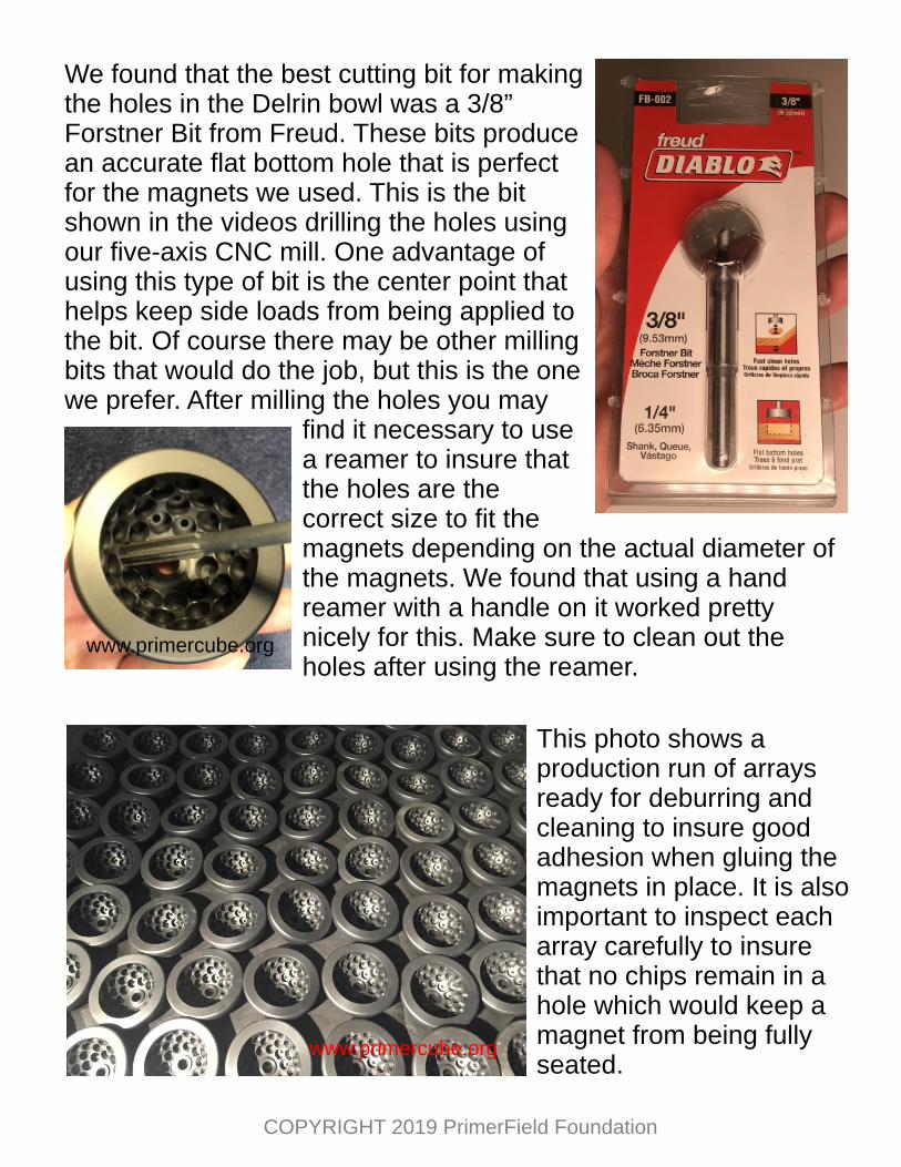
This photo shows a production run of arrays ready for deburring and cleaning to insure good adhesion when gluing the magnets in place. It is also important to inspect each array carefully to insure that no chips remain in a hole which would keep a magnet from being fully seated.
We found that the best cutting bit for making the holes in the Delrin bowl was a 3/8” Forstner Bit from Freud. These bits produce an accurate flat bottom hole that is perfect for the magnets we used. This is the bit shown in the videos drilling the holes using our five-axis CNC mill. One advantage of using this type of bit is the center point that helps keep side loads from being applied to the bit. Of course there may be other milling bits that would do the job, but this is the one we prefer. After milling the holes you may
find it necessary to use a reamer to insure that the holes are the correct size to fit the magnets depending on the actual diameter of the magnets. We found that using a hand reamer with a handle on it worked pretty nicely for this. Make sure to clean out the holes after using the reamer.
www.primercube.org
www.primercube.org
COPYRIGHT 2019 PrimerField Foundation
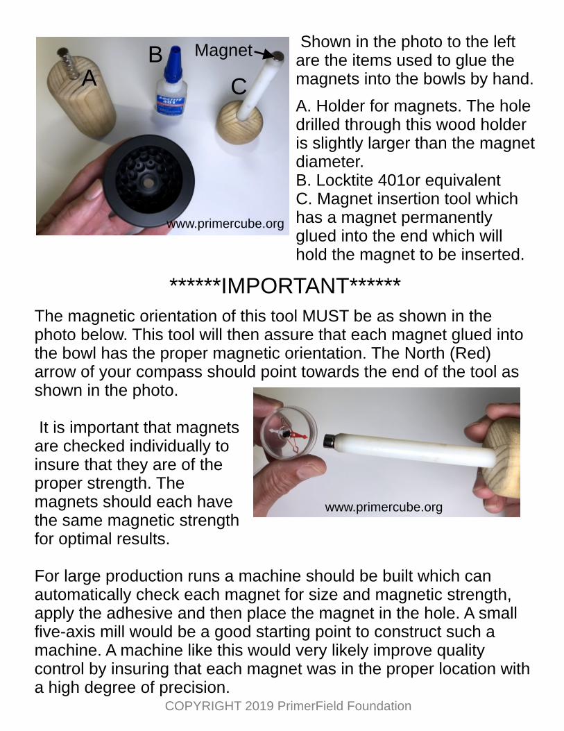
Shown in the photo to the left are the items used to glue the magnets into the bowls by hand.
A. Holder for magnets. The holedrilled through this wood holderis slightly larger than the magnetdiameter.B. Locktite 401or equivalentC. Magnet insertion tool whichhas a magnet permanentlyglued into the end which willhold the magnet to be inserted.
******IMPORTANT******
The magnetic orientation of this tool MUST be as shown in the photo below. This tool will then assure that each magnet glued into the bowl has the proper magnetic orientation. The North (Red) arrow of your compass should point towards the end of the tool as shown in the photo.
It is important that magnets are checked individually to insure that they are of the proper strength. The magnets should each have the same magnetic strength for optimal results.
For large production runs a machine should be built which can automatically check each magnet for size and magnetic strength, apply the adhesive and then place the magnet in the hole. A small five-axis mill would be a good starting point to construct such a machine. A machine like this would very likely improve quality control by insuring that each magnet was in the proper location with a high degree of precision.
AB
C
Magnet
www.primercube.org
www.primercube.org
COPYRIGHT 2019 PrimerField Foundation
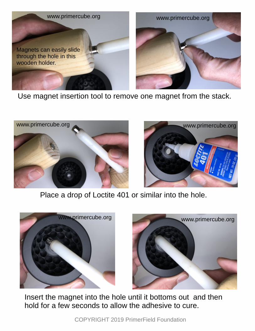
Use magnet insertion tool to remove one magnet from the stack.
Place a drop of Loctite 401 or similar into the hole.
Insert the magnet into the hole until it bottoms out and thenhold for a few seconds to allow the adhesive to cure.
Magnets can easily slidethrough the hole in thiswooden holder.
www.primercube.org www.primercube.org
www.primercube.org www.primercube.org
www.primercube.orgwww.primercube.org
COPYRIGHT 2019 PrimerField Foundation
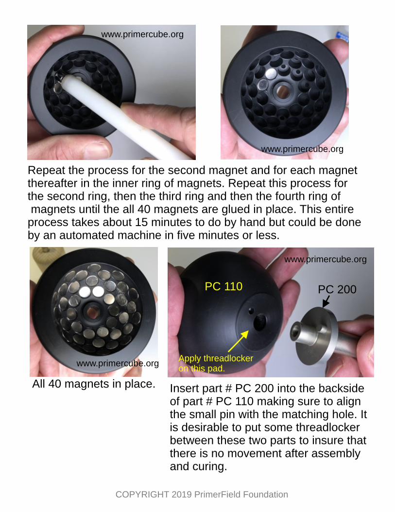
Repeat the process for the second magnet and for each magnetthereafter in the inner ring of magnets. Repeat this process for the second ring, then the third ring and then the fourth ring of magnets until the all 40 magnets are glued in place. This entireprocess takes about 15 minutes to do by hand but could be doneby an automated machine in five minutes or less.
All 40 magnets in place. Insert part # PC 200 into the backside of part # PC 110 making sure to align the small pin with the matching hole. It is desirable to put some threadlocker between these two parts to insure that there is no movement after assembly and curing.
PC 110 PC 200
Apply threadlockeron this pad.
www.primercube.org
www.primercube.org
www.primercube.org
www.primercube.org
COPYRIGHT 2019 PrimerField Foundation
Make sure that PC 200 is fully seated then place part # PC 270 into PC 110. **ASSEMBLY TIP** Although not required it is desirable to put a layer of silicon sealant such as GE5100 on top of the magnets before PC 270 is inserted into PC 110 as this helps keep the magnets firmly in place. A loose magnet can lead to undesirable vibration.
PC 270
PC 110
PC 110
PC 200
PC 210
MCM 92125A238
Insert screw # MCM 92125A238 into PC 210 and then put a drop of threadlocker on the screw.
Insert screw and tighten until firmly seated.
www.primercube.org www.primercube.org
www.primercube.org www.primercube.org
COPYRIGHT 2019 PrimerField Foundation
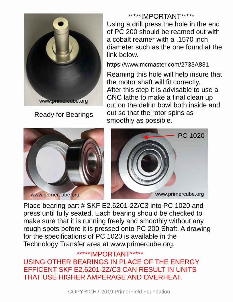
Ready for Bearings
PC 1020
Place bearing part # SKF E2.6201-2Z/C3 into PC 1020 and press until fully seated. Each bearing should be checked to make sure that it is running freely and smoothly without any rough spots before it is pressed onto PC 200 Shaft. A drawing for the specifications of PC 1020 is available in the Technology Transfer area at www.primercube.org.
*****IMPORTANT*****USING OTHER BEARINGS IN PLACE OF THE ENERGY EFFICENT SKF E2.6201-2Z/C3 CAN RESULT IN UNITS THAT USE HIGHER AMPERAGE AND OVERHEAT.
*****IMPORTANT*****Using a drill press the hole in the end of PC 200 should be reamed out with a cobalt reamer with a .1570 inch diameter such as the one found at the link below.
https://www.mcmaster.com/2733A831
Reaming this hole will help insure that the motor shaft will fit correctly.After this step it is advisable to use a CNC lathe to make a final clean up cut on the delrin bowl both inside and out so that the rotor spins as smoothly as possible.
www.primercube.org
www.primercube.org www.primercube.org
COPYRIGHT 2019 PrimerField Foundation
Bearing should be a press fit for the smoothest running assembly. The drawing for part # PC 200 on specifies a shaft diameter for the correct press fit.
Each part #PC 200 should be checked to insure the correct shaft diameter before pressing the bearing onto the shaft.
*******IMPORTANT******Only press on the inner ring of the bearing to avoid damaging the bearing.
www.primercube.org
Attach McM 9714K65 (Wave Spring) in place with GE5100 Silicone Sealant onto the second PC 1020.
Only use a small amount of silicone sealant at each of the three spots of the wave spring that contact PC 1020 so that the silicone sealant does not interfere with the spring fully compressing.
The Silicone should cure for three hours after application before further assembly. It is easiest to silicone the wave springs in place on all the PC 1020s well ahead of the time they will be required in your production run.
*****IMPORTANT*****
OMITTING THIS WAVESPRING WILL RESULT IN THE BEARINGS PRODUCING UNDESIRABLE VIBRATION.
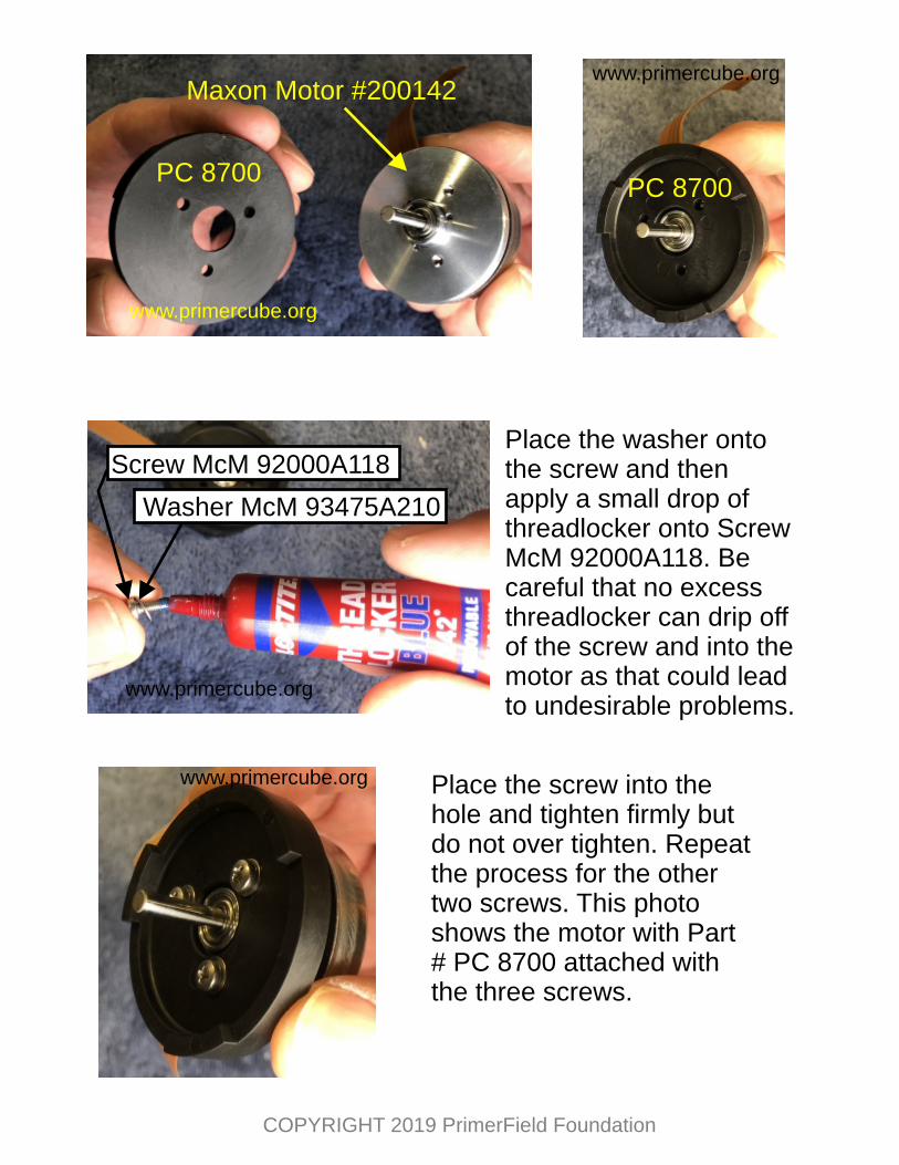
Place the washer onto the screw and then apply a small drop of threadlocker onto Screw McM 92000A118. Be careful that no excess threadlocker can drip off of the screw and into the motor as that could lead to undesirable problems.
Place the screw into the hole and tighten firmly but do not over tighten. Repeat the process for the other two screws. This photo shows the motor with Part # PC 8700 attached with the three screws.
www.primercube.org
www.primercube.org
www.primercube.org
www.primercube.org
COPYRIGHT 2019 PrimerField Foundation
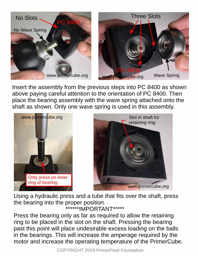
Insert the assembly from the previous steps into PC 8400 as shown above paying careful attention to the orientation of PC 8400. Then place the bearing assembly with the wave spring attached onto the shaft as shown. Only one wave spring is used in this assembly.
Using a hydraulic press and a tube that fits over the shaft, press the bearing into the proper position. ******IMPORTANT*****Press the bearing only as far as required to allow the retaining ring to be placed in the slot on the shaft. Pressing the bearing past this point will place undesirable excess loading on the balls in the bearings. This will increase the amperage required by the motor and increase the operating temperature of the PrimerCube.
No Slots Three SlotsPC 8400
PC 8400
No Wave Spring
Wave Spring
Slot in shaft forretaining ring.
Only press on innerring of bearing.
www.primercube.org www.primercube.org
www.primercube.org
www.primercube.org
COPYRIGHT 2019 PrimerField Foundation
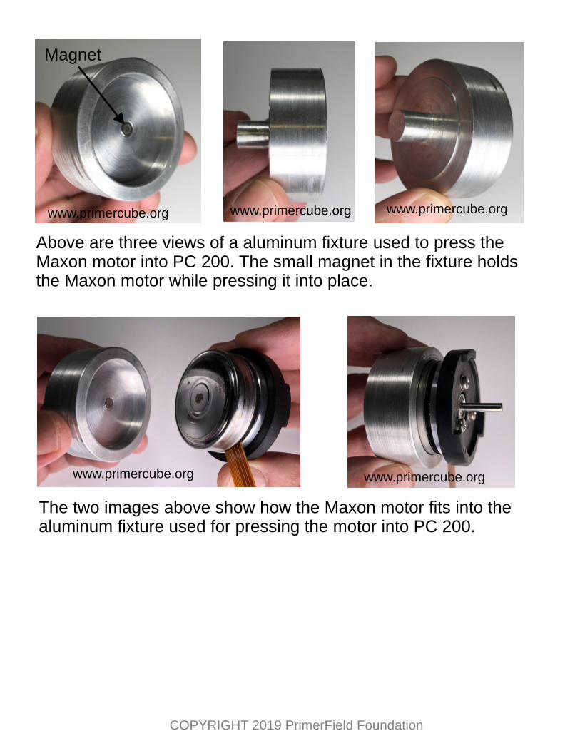
Above are three views of a aluminum fixture used to press the Maxon motor into PC 200. The small magnet in the fixture holds the Maxon motor while pressing it into place.
Magnet
The two images above show how the Maxon motor fits into the aluminum fixture used for pressing the motor into PC 200.
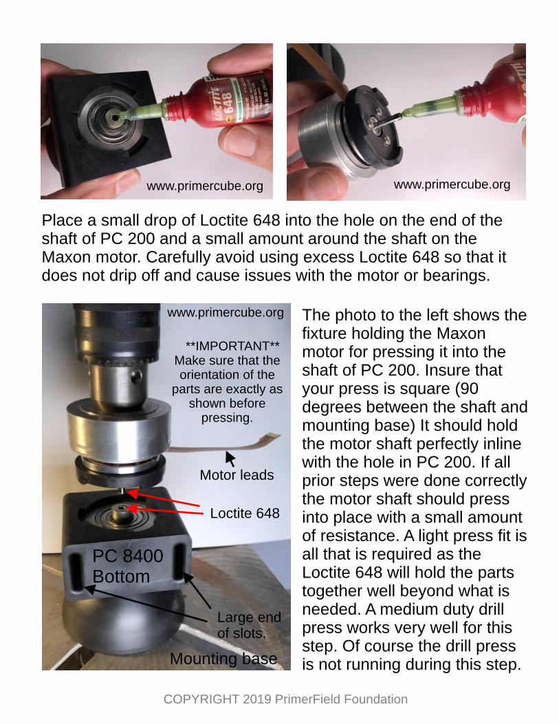
Place a small drop of Loctite 648 into the hole on the end of the shaft of PC 200 and a small amount around the shaft on the Maxon motor. Carefully avoid using excess Loctite 648 so that it does not drip off and cause issues with the motor or bearings.
www.primercube.org www.primercube.org
www.primercube.org
Motor leads
PC 8400Bottom
Large endof slots.
Loctite 648
The photo to the left shows the fixture holding the Maxon motor for pressing it into the shaft of PC 200. Insure that your press is square (90 degrees between the shaft and mounting base) It should hold the motor shaft perfectly inline with the hole in PC 200. If all prior steps were done correctly the motor shaft should press into place with a small amount of resistance. A light press fit is all that is required as the Loctite 648 will hold the parts together well beyond what is needed. A medium duty drill press works very well for this step. Of course the drill press is not running during this step.Mounting base
**IMPORTANT**Make sure that the orientation of the
parts are exactly as shown before
pressing.
COPYRIGHT 2019 PrimerField Foundation
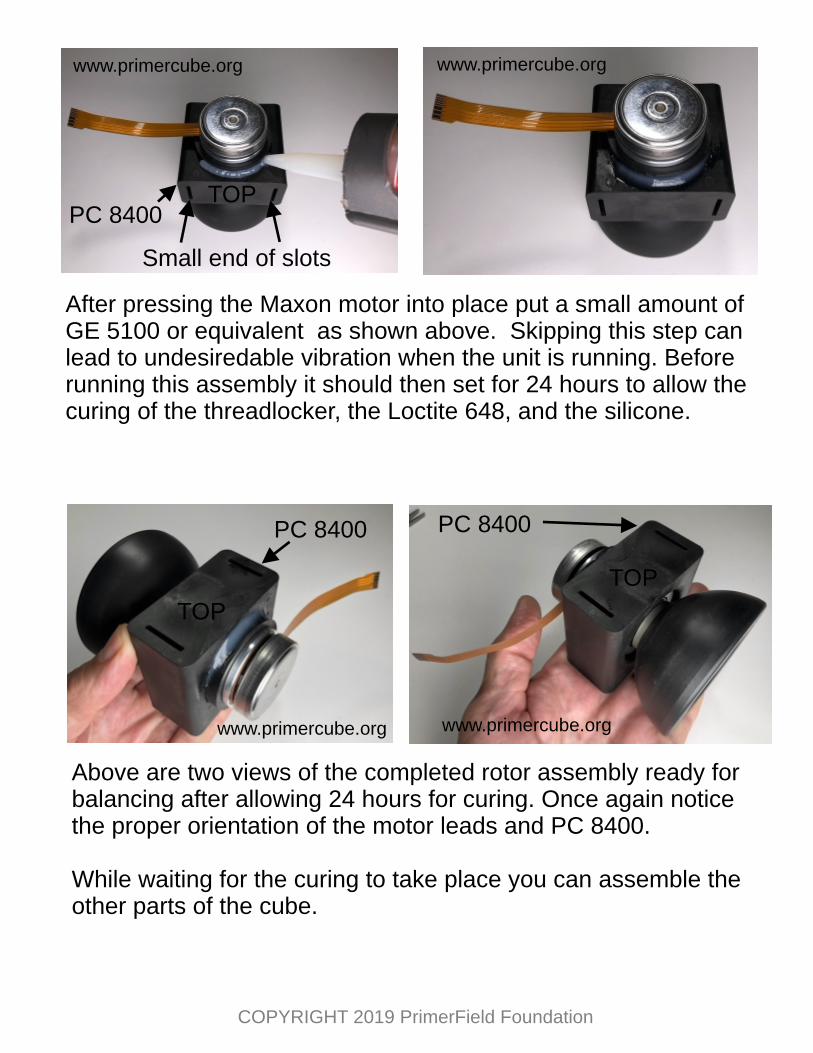
After pressing the Maxon motor into place put a small amount of GE 5100 or equivalent as shown above. Skipping this step can lead to undesiredable vibration when the unit is running. Before running this assembly it should then set for 24 hours to allow the curing of the threadlocker, the Loctite 648, and the silicone.
www.primercube.org www.primercube.org
PC 8400TOP
Small end of slots
Above are two views of the completed rotor assembly ready for balancing after allowing 24 hours for curing. Once again notice the proper orientation of the motor leads and PC 8400.
While waiting for the curing to take place you can assemble the other parts of the cube.
PC 8400 PC 8400
TOP
TOP
www.primercube.org www.primercube.org
COPYRIGHT 2019 PrimerField Foundation
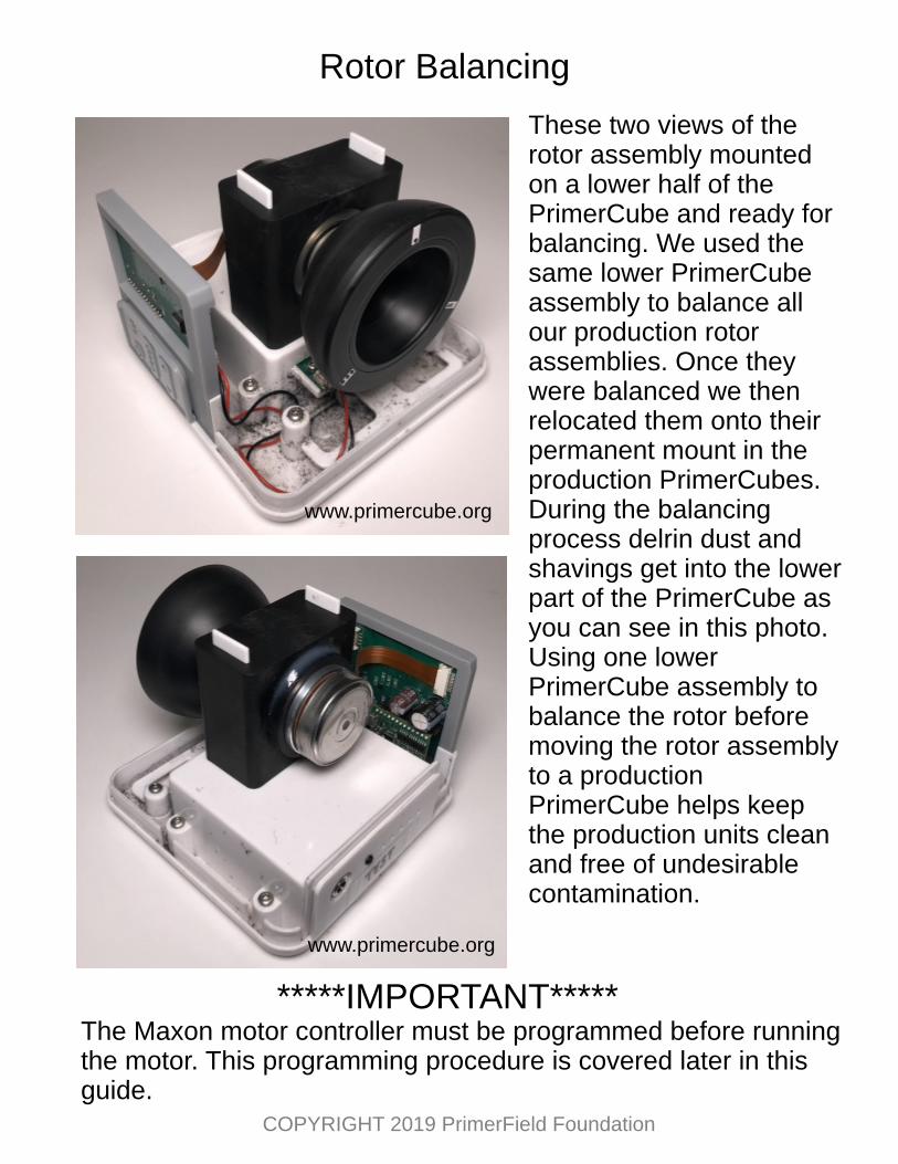
Rotor Balancing
These two views of the rotor assembly mounted on a lower half of the PrimerCube and ready for balancing. We used the same lower PrimerCube assembly to balance all our production rotor assemblies. Once they were balanced we then relocated them onto their permanent mount in the production PrimerCubes. During the balancing process delrin dust and shavings get into the lower part of the PrimerCube as you can see in this photo. Using one lower PrimerCube assembly to balance the rotor before moving the rotor assembly to a production PrimerCube helps keep the production units clean and free of undesirable contamination.
*****IMPORTANT*****The Maxon motor controller must be programmed before running the motor. This programming procedure is covered later in this guide.
www.primercube.org
www.primercube.org
COPYRIGHT 2019 PrimerField Foundation
The image above shows the items required to balance the rotor assembly in about 20 minutes per unit. A custom balancing machine should be used for large production as that would greatly reduce the time required per unit. Shown in the image above are:
A: iPad with iRotorBalance app.B: Small precision scale with .01 gram accuracyC: Modeling clay D: iPhone with Vibration measuring app.E: Rotor assembly to be balanced.F: Wooden platform to hold iPhone and PrimerCube base.
We used the single plane (4 runs) method on the iRotorBalance app in the balancing procedure.
A
E
D
C
BF
www.primercube.org
COPYRIGHT 2019 PrimerField Foundation
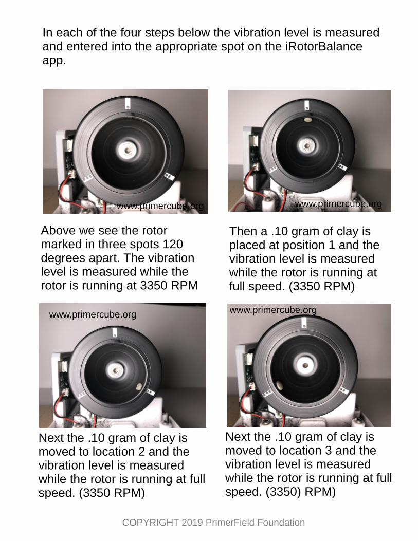
Above we see the rotor marked in three spots 120 degrees apart. The vibration level is measured while the rotor is running at 3350 RPM
Then a .10 gram of clay is placed at position 1 and the vibration level is measured while the rotor is running at full speed. (3350 RPM)
Next the .10 gram of clay is moved to location 2 and the vibration level is measured while the rotor is running at full speed. (3350 RPM)
Next the .10 gram of clay is moved to location 3 and the vibration level is measured while the rotor is running at full speed. (3350) RPM)
In each of the four steps below the vibration level is measured and entered into the appropriate spot on the iRotorBalance app.
www.primercube.org
www.primercube.org www.primercube.org
www.primercube.org
COPYRIGHT 2019 PrimerField Foundation
For production balancing we suggest you contact companies that produce balancing machines. They will be able to assist you with the balancing equipment and procedures that will produce the best results with far less time needed per unit. You may find that a much better method and balancing weight approach is available than what is outlined here. We are just showing you the method we used so that balancing equipment providers are better prepared to suggest the best approach to achieving the smoothest running rotor assembly.
We are not providing the complete instructions on proper use of the iRotorBalance app to balance the rotor assembly as this guide is intended for manufacturers who will most likely not use this app.
After a bit of fine tuning we have the proper weight and location of the two temporary clay balancing weights required for a smooth running rotor. The photo to the right shows the temporary balance weight on the motor, but some rotors do not need this balancing weight as they are smooth enough with just the balancing weight on one side of the bearings.
www.primercube.orgwww.primercube.org
COPYRIGHT 2019 PrimerField Foundation
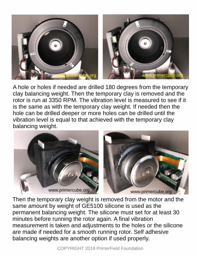
A hole or holes if needed are drilled 180 degrees from the temporary clay balancing weight. Then the temporary clay is removed and the rotor is run at 3350 RPM. The vibration level is measured to see if it is the same as with the temporary clay weight. If needed then the hole can be drilled deeper or more holes can be drilled until the vibration level is equal to that achieved with the temporary clay balancing weight.
Then the temporary clay weight is removed from the motor and the same amount by weight of GE5100 silicone is used as the permanent balancing weight. The silicone must set for at least 30 minutes before running the rotor again. A final vibration measurement is taken and adjustments to the holes or the silicone are made if needed for a smooth running rotor. Self adhesive balancing weights are another option if used properly.
www.primercube.orgwww.primercube.org
www.primercube.org www.primercube.org
COPYRIGHT 2019 PrimerField Foundation
To the top left is a screenshot of the desired vibration readings using the Vibration app on the iPhone. These readings were obtained using the simple setup shown in the image below.
It has not been scientifically established that a smoother running PrimerCube produces better health effects, but users of PrimerCubes definitely prefer a smoother running and therefore quieter unit.
A PrimerCube balanced to the vibration levels shown here will have a sound measurement level of less than 50 dB (Decibels) at a distance of 12 inches (30 cm) . The image to the left shows a sound level measurement taken using the iPhone app “Decibel X” 12 inches from the PrimerCube. This sound level is just slightly above that of a typical quiet room.
www.primercube.org
COPYRIGHT 2019 PrimerField Foundation
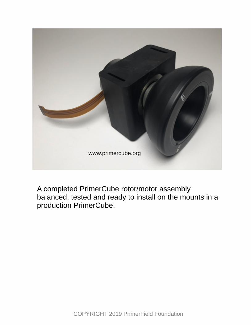
A completed PrimerCube rotor/motor assembly balanced, tested and ready to install on the mounts in a production PrimerCube.
www.primercube.org
COPYRIGHT 2019 PrimerField Foundation
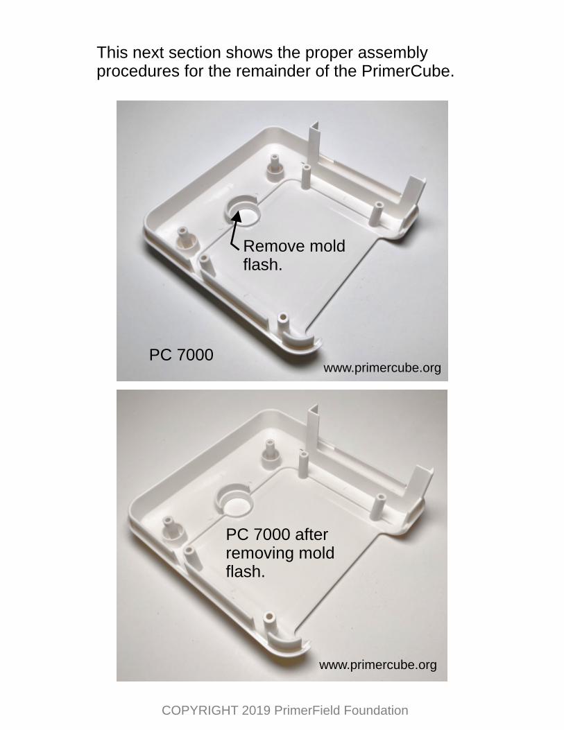
This next section shows the proper assembly procedures for the remainder of the PrimerCube.
PC 7000
Remove moldflash.
PC 7000 after removing moldflash.
www.primercube.org
www.primercube.org
COPYRIGHT 2019 PrimerField Foundation
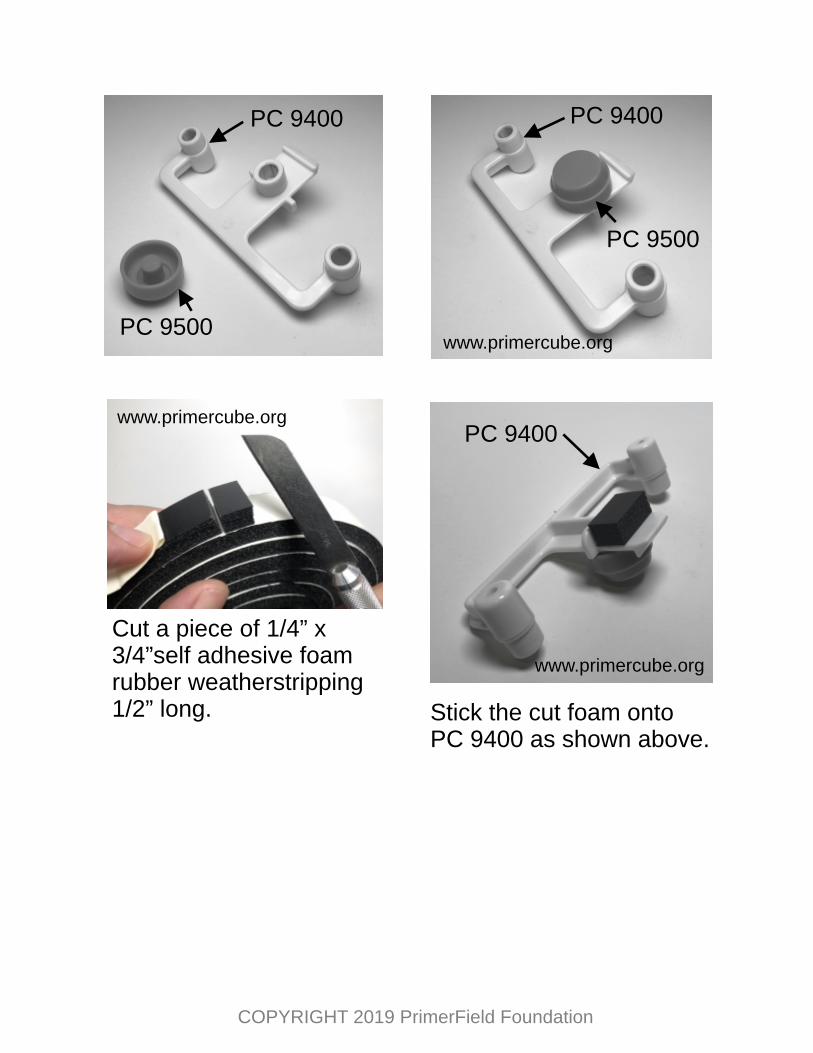
PC 9500
PC 9400
PC 9500
PC 9400
Cut a piece of 1/4” x 3/4”self adhesive foam rubber weatherstripping 1/2” long.
PC 9400
Stick the cut foam onto PC 9400 as shown above.
www.primercube.org
www.primercube.org
www.primercube.org
COPYRIGHT 2019 PrimerField Foundation
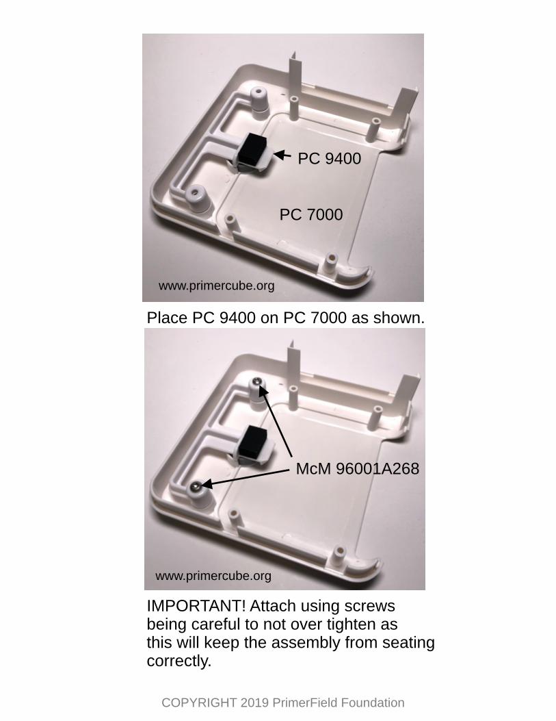
PC 9400
PC 7000
Place PC 9400 on PC 7000 as shown.
McM 96001A268
IMPORTANT! Attach using screws being careful to not over tighten as this will keep the assembly from seatingcorrectly.
www.primercube.org
www.primercube.org
COPYRIGHT 2019 PrimerField Foundation
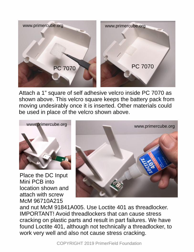
PC 7070PC 7070
Attach a 1” square of self adhesive velcro inside PC 7070 asshown above. This velcro square keeps the battery pack frommoving undesirably once it is inserted. Other materials could be used in place of the velcro shown above.
Place the DC Input Mini PCB into location shown and attach with screw McM 96710A215 and nut McM 91841A005. Use Loctite 401 as threadlocker. IMPORTANT! Avoid threadlockers that can cause stress cracking on plastic parts and result in part failures. We have found Loctite 401, although not technically a threadlocker, to work very well and also not cause stress cracking.
www.primercube.org www.primercube.org
www.primercube.orgwww.primercube.org
COPYRIGHT 2019 PrimerField Foundation
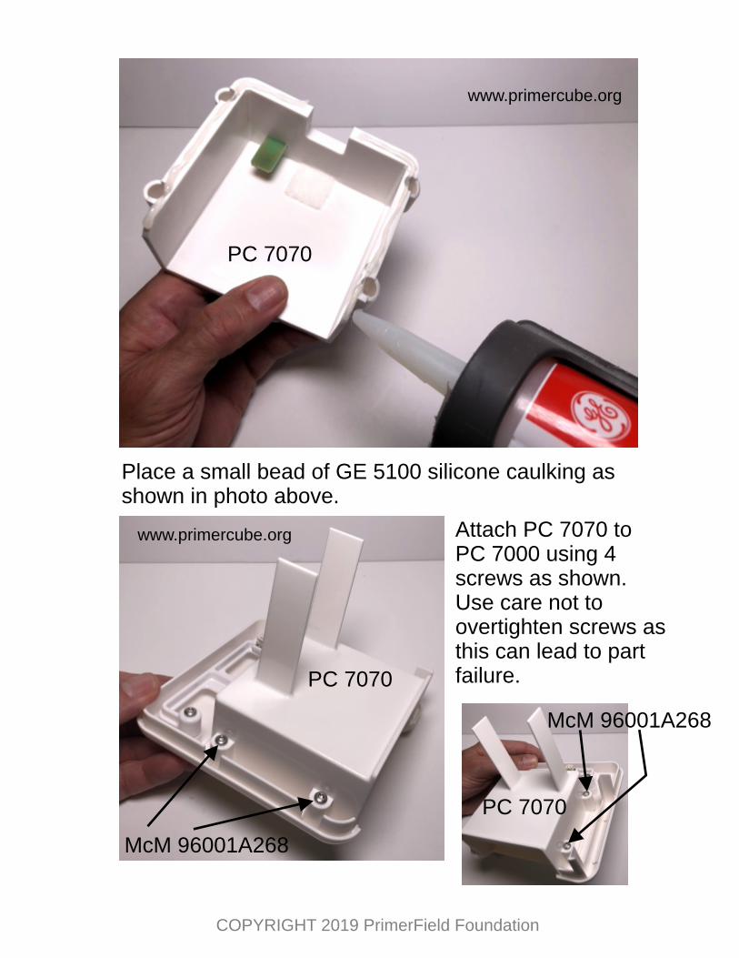
Place a small bead of GE 5100 silicone caulking as shown in photo above.
PC 7070
Attach PC 7070 to PC 7000 using 4 screws as shown. Use care not to overtighten screws as this can lead to part failure.PC 7070
McM 96001A268
www.primercube.org
www.primercube.org
PC 7070
McM 96001A268
COPYRIGHT 2019 PrimerField Foundation
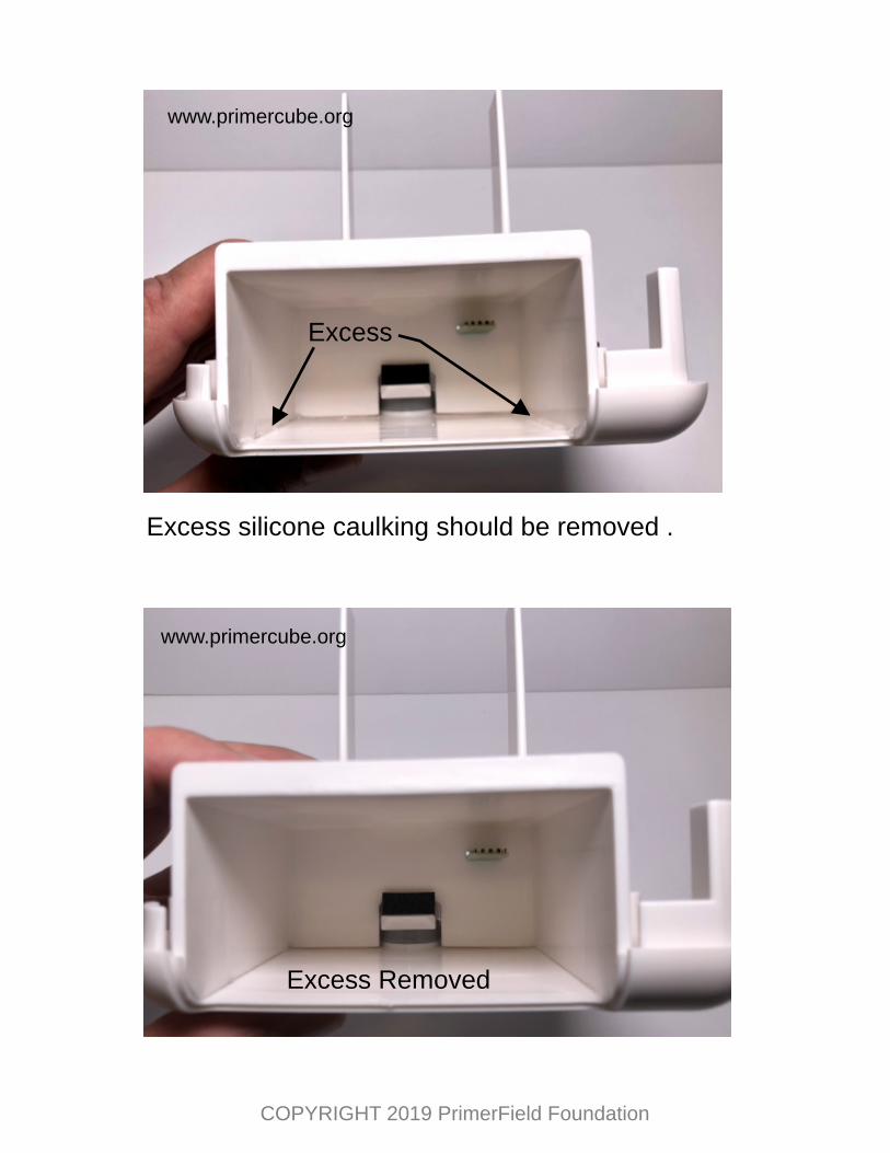
Excess silicone caulking should be removed .
Excess
Excess Removed
www.primercube.org
www.primercube.org
COPYRIGHT 2019 PrimerField Foundation
PC 7200
Insert PrimerCube Motherboard into PC 7200 and then placeinto PC 7000 as shown below.
Connect PrimerCube motherboard to the DC Input PCB usingScondar part # SCT2001H02 H2L200.
Scondar#SCT2001H02H2L200
www.primercube.orgwww.primercube.org
www.primercube.org
www.primercube.org
COPYRIGHT 2019 PrimerField Foundation
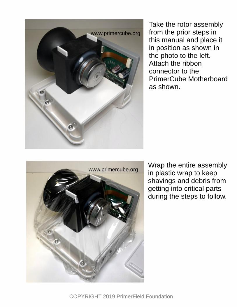
Take the rotor assembly from the prior steps in this manual and place it in position as shown in the photo to the left. Attach the ribbon connector to the PrimerCube Motherboard as shown.
Wrap the entire assembly in plastic wrap to keep shavings and debris from getting into critical parts during the steps to follow.
www.primercube.org
www.primercube.org
COPYRIGHT 2019 PrimerField Foundation
PC 8600 Place PC 8600 in position as shown.
Using a .077 inch diameter drill bit make six holes in the locations indicated by the marks on PC 8600. The holes should be about ½ inch deep. Keep the drill bit at 90 degrees to the surface with the location marks as shown in the photo.
www.primercube.org
www.primercube.org
COPYRIGHT 2019 PrimerField Foundation
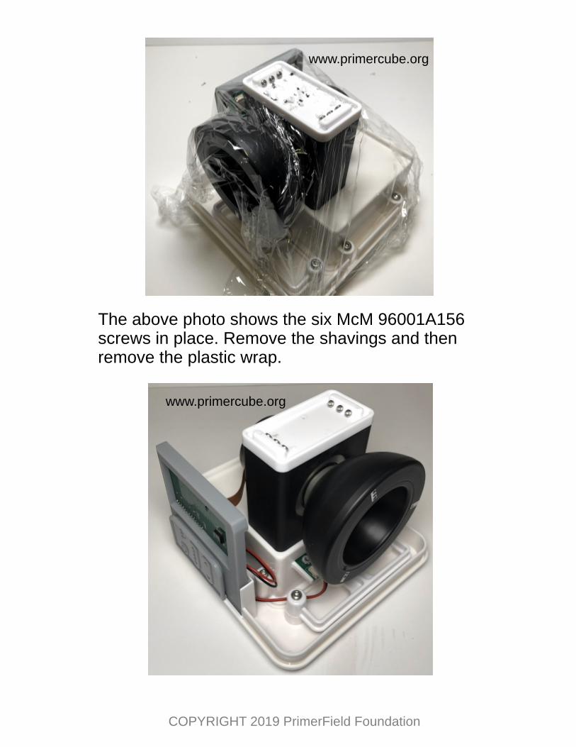
The above photo shows the six McM 96001A156 screws in place. Remove the shavings and then remove the plastic wrap.
www.primercube.org
www.primercube.org
COPYRIGHT 2019 PrimerField Foundation
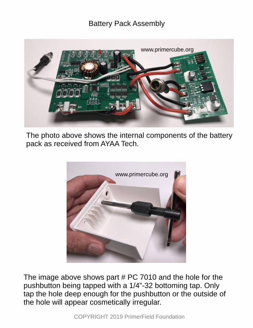
Battery Pack Assembly
The photo above shows the internal components of the battery pack as received from AYAA Tech.
The image above shows part # PC 7010 and the hole for the pushbutton being tapped with a 1/4”-32 bottoming tap. Only tap the hole deep enough for the pushbutton or the outside of the hole will appear cosmetically .irregular
www.primercube.org
www.primercube.org
COPYRIGHT 2019 PrimerField Foundation
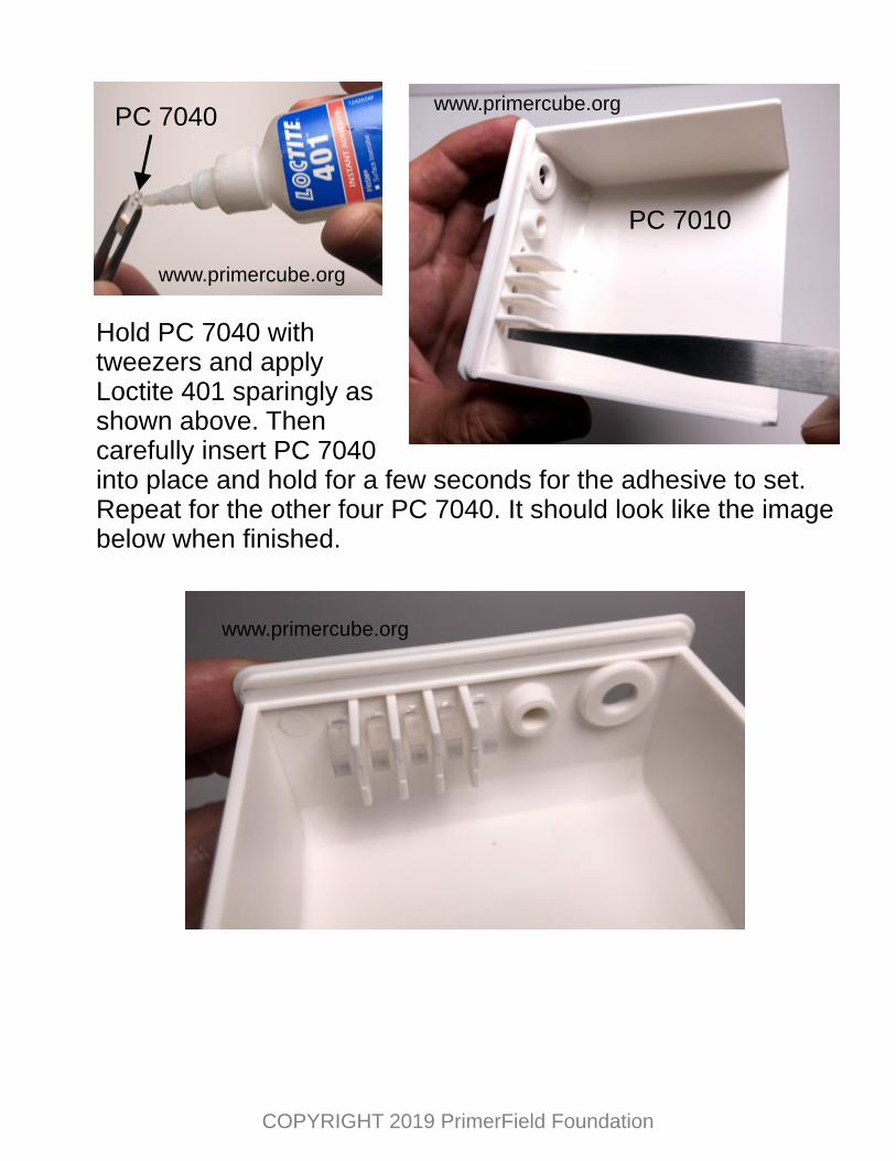
Hold PC 7040 with tweezers and apply Loctite 401 sparingly as shown above. Then carefully insert PC 7040 into place and hold for a few seconds for the adhesive to set. Repeat for the other four PC 7040. It should look like the image below when finished.
PC 7040
PC 7010
www.primercube.org
www.primercube.org
www.primercube.org
COPYRIGHT 2019 PrimerField Foundation
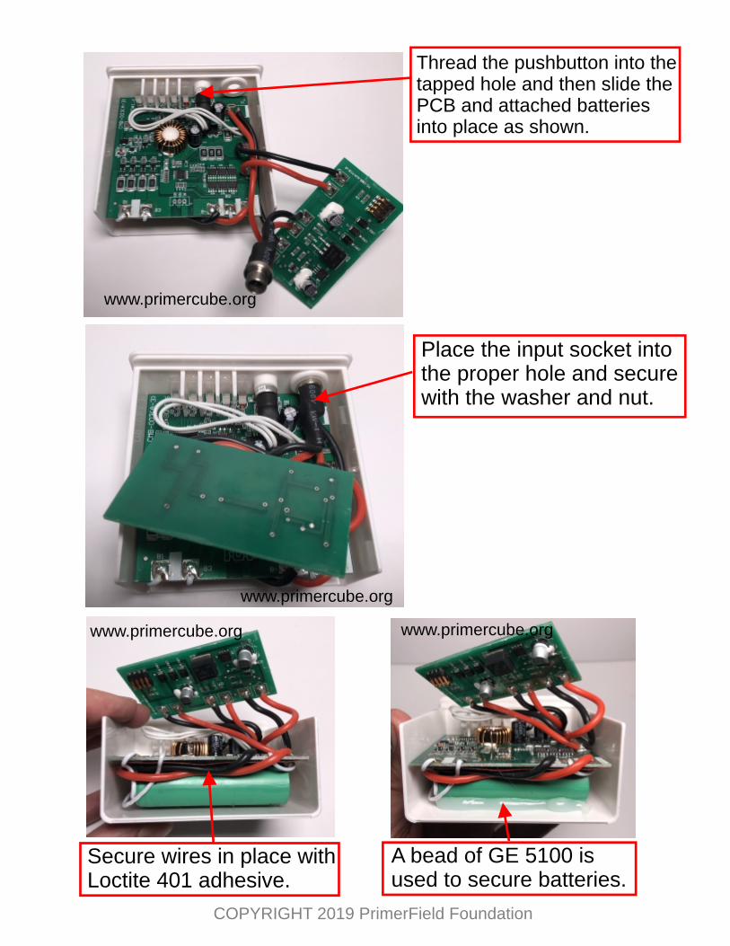
Thread the pushbutton into the tapped hole and then slide the PCB and attached batteries into place as shown.
Place the input socket into the proper hole and secure with the washer and nut.
Secure wires in place with Loctite 401 adhesive.
A bead of GE 5100 is used to secure batteries.
www.primercube.org
www.primercube.org
www.primercube.org www.primercube.org
COPYRIGHT 2019 PrimerField Foundation
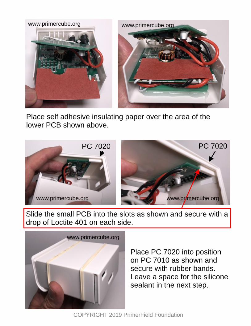
Place self adhesive insulating paper over the area of the lower PCB shown above.
PC 7020 PC 7020
Slide the small PCB into the slots as shown and secure with a drop of Loctite 401 on each side.
Place PC 7020 into position on PC 7010 as shown and secure with rubber bands. Leave a space for the silicone sealant in the next step.
www.primercube.org www.primercube.org
www.primercube.org www.primercube.org
www.primercube.org
COPYRIGHT 2019 PrimerField Foundation
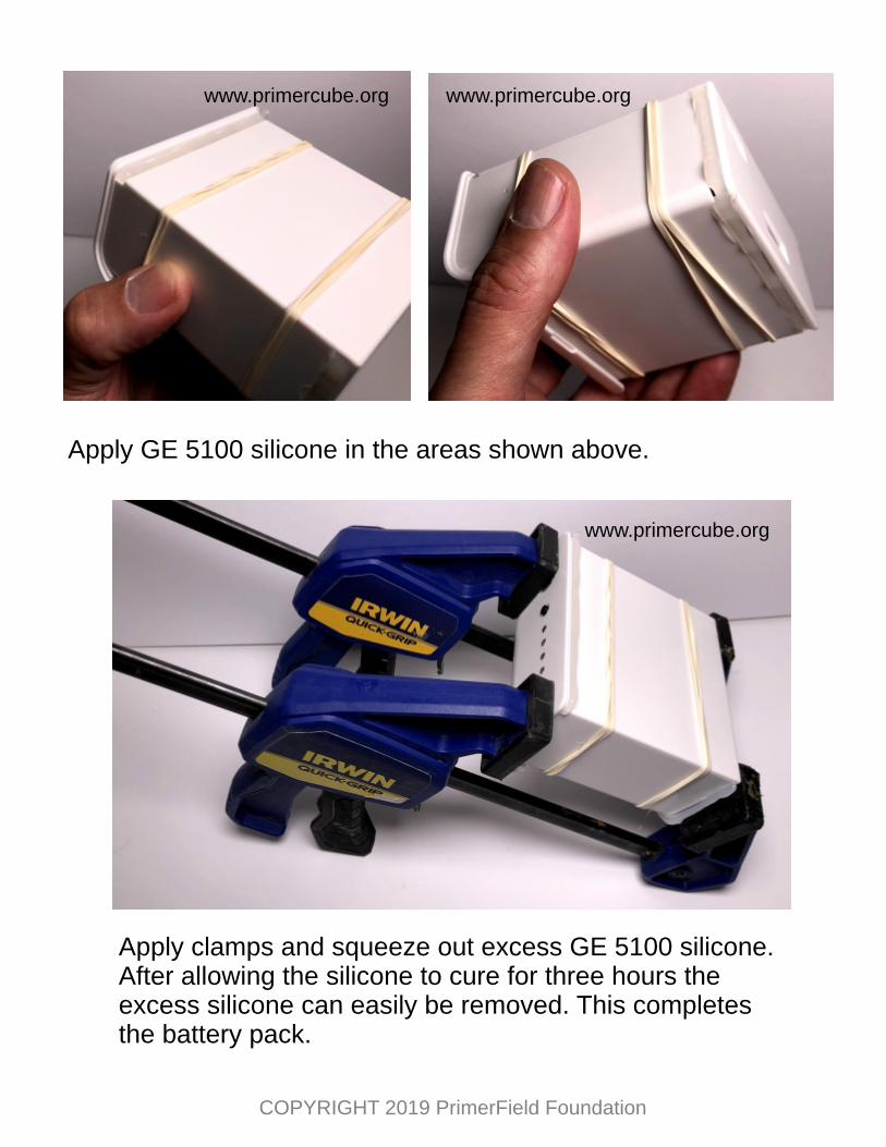
Apply GE 5100 silicone in the areas shown above.
Apply clamps and squeeze out excess GE 5100 silicone. After allowing the silicone to cure for three hours the excess silicone can easily be removed. This completes the battery pack.
www.primercube.org www.primercube.org
www.primercube.org
COPYRIGHT 2019 PrimerField Foundation
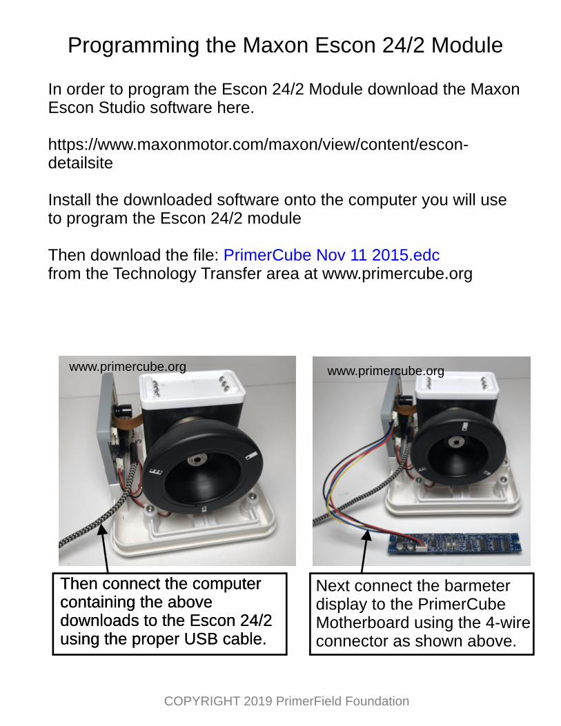
Programming the Maxon Escon 24/2 Module
In order to program the Escon 24/2 Module download the Maxon Escon Studio software here.
Install the downloaded software onto the computer you will use to program the Escon 24/2 module
Then download the file: from the Technology Transfer area at www.primercube.org
PrimerCube Nov 11 2015.edc
Then connect the computer containing the above downloads to the Escon 24/2 using the proper USB cable.
Next connect the barmeter display to the PrimerCube Motherboard using the 4-wireconnector as shown above.
Then connect the computer containing the above downloads to the Escon 24/2 using the proper USB cable.
www.primercube.org www.primercube.org
COPYRIGHT 2019 PrimerField Foundation
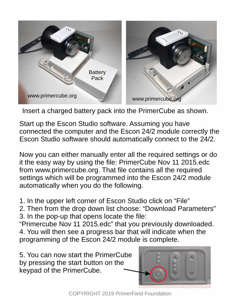
Insert a charged battery pack into the PrimerCube as shown.
BatteryPack
Start up the Escon Studio software. Assuming you have connected the computer and the Escon 24/2 module correctly the Escon Studio software should automatically connect to the 24/2.
Now you can either manually enter all the required settings or do it the easy way by using the file: PrimerCube Nov 11 2015.edc from www.primercube.org. That file contains all the required settings which will be programmed into the Escon 24/2 module automatically when you do the following.
1. In the upper left corner of Escon Studio click on “File”2. Then from the drop down list choose: “Download Parameters”3. In the pop-up that opens locate the file:“Primercube Nov 11 2015.edc” that you previously downloaded.4. You will then see a progress bar that will indicate when the programming of the Escon 24/2 module is complete.
5. You can now start the PrimerCube by pressing the start button on the keypad of the PrimerCube.
www.primercube.orgwww.primercube.org
COPYRIGHT 2019 PrimerField Foundation
As mentioned previously you can also choose to enter all the parameters for the Escon 24/2 module individually. You can find these settings in the Technology Transfer area at
in the Maxon motors section. In that section you will find screen captures from the Escon Studio software that shows these settings and where they are entered. These twelve screen captures are labeled:“Settings for 24 2 A” through “Settings for 24 2 L”
Some of the important settings for the 24/2 module include the speed settings. The lowest speed programmed into the PrimerCube 24/2 module is 1000 RPM. This means that when the PrimerCube is running it can be adjusted to a speed no lower than 1000 RPM. The reason for this is that we believe there is no benefit to using the PrimerCube when it is running at a speed slower than this.
Then you will see that the programming for the highest speed the PrimerCube will run at is 3350 RPM. The reason for limiting the highest speed to 3350 RPM is that speeds beyond this point can actually induce temporary pain in some cases. So to avoid this issue we have limited the PrimerCubes to this maximum speed of 3350 RPM. We expect that other researchers will try to up this maximum speed to see if a higher RPM would be an advantage in treating certain issues and ailments more effectively. But we encourage those involved to be extremely cautious when doing so. We have not seen any lasting negative effects from going over this 3350 RPM, and typically any pain caused by exceeding this limit disappear within minutes of turning the PrimerCube off.
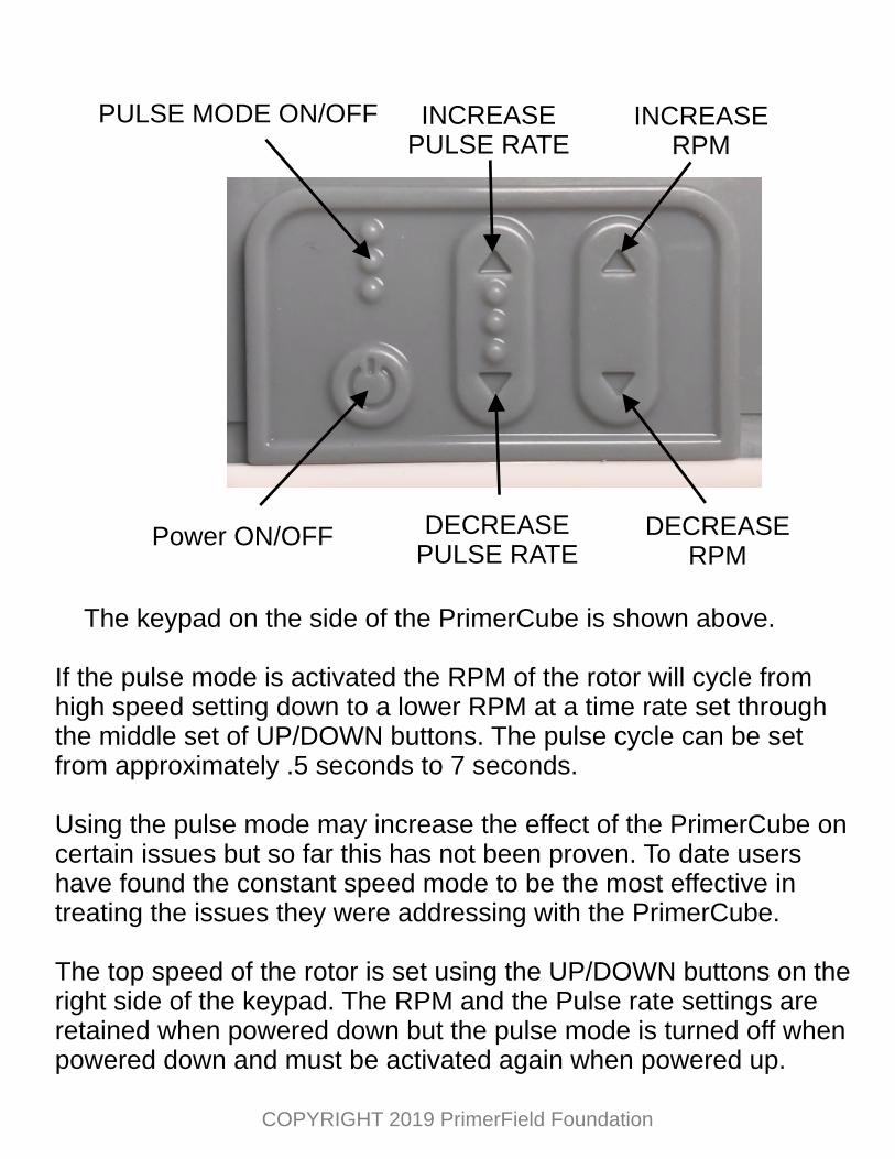
The keypad on the side of the PrimerCube is shown above.
If the pulse mode is activated the RPM of the rotor will cycle from high speed setting down to a lower RPM at a time rate set through the middle set of UP/DOWN buttons. The pulse cycle can be set from approximately .5 seconds to 7 seconds.
Using the pulse mode may increase the effect of the PrimerCube on certain issues but so far this has not been proven. To date users have found the constant speed mode to be the most effective in treating the issues they were addressing with the PrimerCube.
The top speed of the rotor is set using the UP/DOWN buttons on the right side of the keypad. The RPM and the Pulse rate settings are retained when powered down but the pulse mode is turned off when powered down and must be activated again when powered up.
COPYRIGHT 2019 PrimerField Foundation
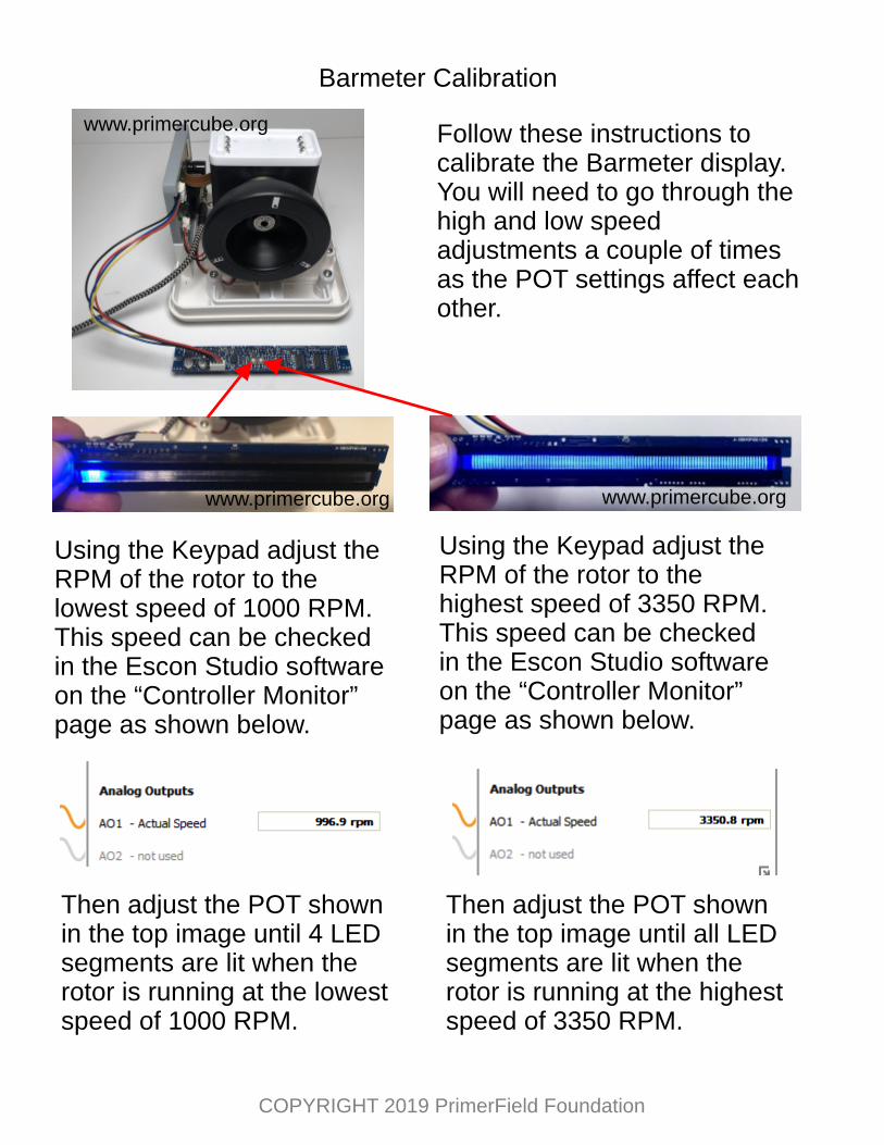
Barmeter Calibration
Using the Keypad adjust the RPM of the rotor to the lowest speed of 1000 RPM. This speed can be checked in the Escon Studio software on the “Controller Monitor” page as shown below.
Then adjust the POT shown in the top image until 4 LED segments are lit when the rotor is running at the lowest speed of 1000 RPM.
Using the Keypad adjust the RPM of the rotor to the highest speed of 3350 RPM. This speed can be checked in the Escon Studio software on the “Controller Monitor” page as shown below.
Then adjust the POT shown in the top image until all LED segments are lit when the rotor is running at the highest speed of 3350 RPM.
Follow these instructions to calibrate the Barmeter display. You will need to go through the high and low speed adjustments a couple of times as the POT settings affect each other.
www.primercube.org
www.primercube.org www.primercube.org
COPYRIGHT 2019 PrimerField Foundation
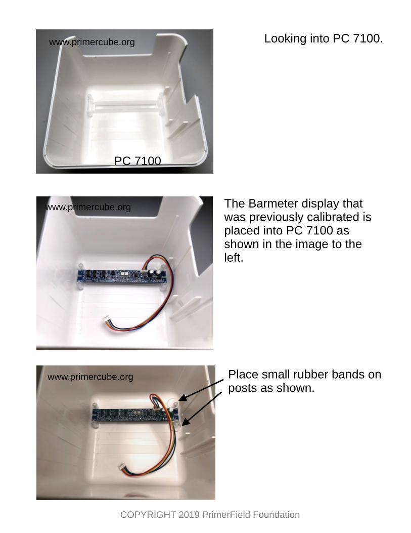
PC 7100
Looking into PC 7100.
The Barmeter display that was previously calibrated is placed into PC 7100 as shown in the image to the left.
Place small rubber bands on posts as shown.
www.primercube.org
www.primercube.org
www.primercube.org
COPYRIGHT 2019 PrimerField Foundation
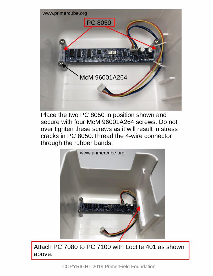
PC 8050
McM 96001A264
Place the two PC 8050 in position shown and secure with four McM 96001A264 screws. Do not over tighten these screws as it will result in stress cracks in PC 8050.Thread the 4-wire connector through the rubber bands.
Attach PC 7080 to PC 7100 with Loctite 401 as shown above.
www.primercube.org
www.primercube.org
COPYRIGHT 2019 PrimerField Foundation
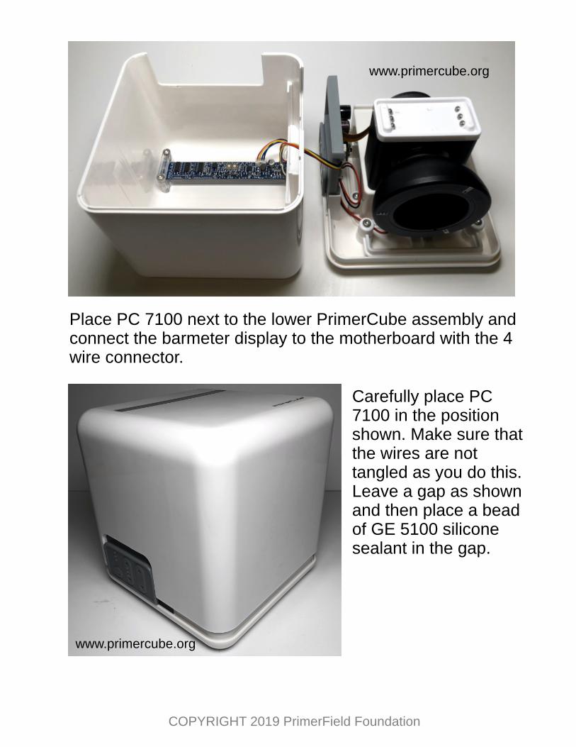
Place PC 7100 next to the lower PrimerCube assembly and connect the barmeter display to the motherboard with the 4 wire connector.
Carefully place PC 7100 in the position shown. Make sure that the wires are not tangled as you do this. Leave a gap as shown and then place a bead of GE 5100 silicone sealant in the gap.
www.primercube.org
www.primercube.org
COPYRIGHT 2019 PrimerField Foundation
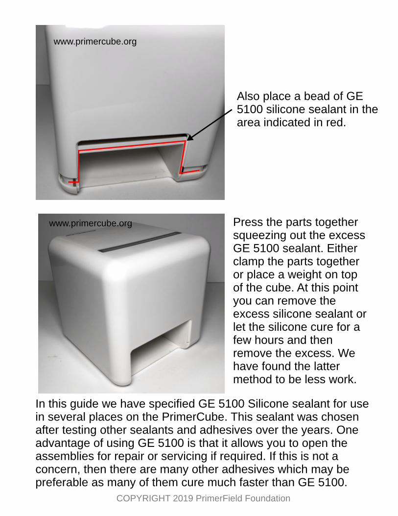
Also place a bead of GE 5100 silicone sealant in the area indicated in red.
Press the parts together squeezing out the excess GE 5100 sealant. Either clamp the parts together or place a weight on top of the cube. At this point you can remove the excess silicone sealant or let the silicone cure for a few hours and then remove the excess. We have found the latter method to be less work.
www.primercube.org
www.primercube.org
COPYRIGHT 2019 PrimerField Foundation
In this guide we have specified GE 5100 Silicone sealant for use in several places on the PrimerCube. This sealant was chosen after testing other sealants and adhesives over the years. One advantage of using GE 5100 is that it allows you to open the assemblies for repair or servicing if required. If this is not a concern, then there are many other adhesives which may be preferable as many of them cure much faster than GE 5100.
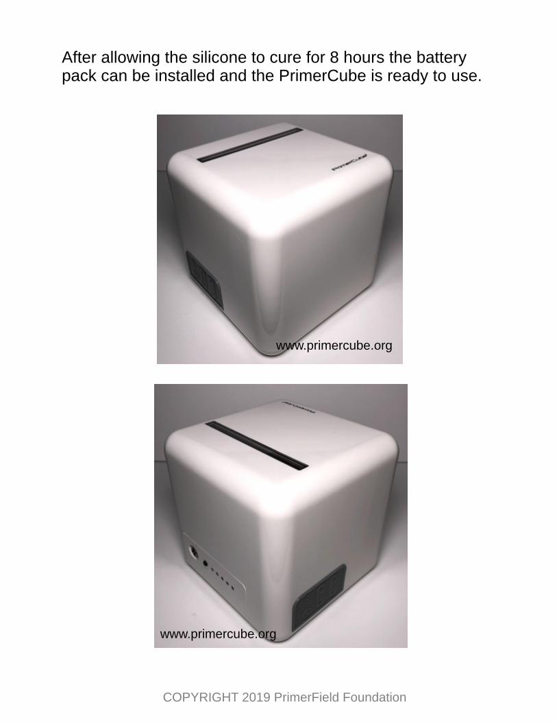
After allowing the silicone to cure for 8 hours the battery pack can be installed and the PrimerCube is ready to use.
www.primercube.org
www.primercube.org
COPYRIGHT 2019 PrimerField Foundation
Although this guide shows how to manufacture a PrimerCube exactly as the units that are currently in use around the world, it is clear that modifications could be made to this design without any change in the effectiveness of the units produced. In fact we encourage modifications and improvements to the current design if these changes are a benefit to the end user.
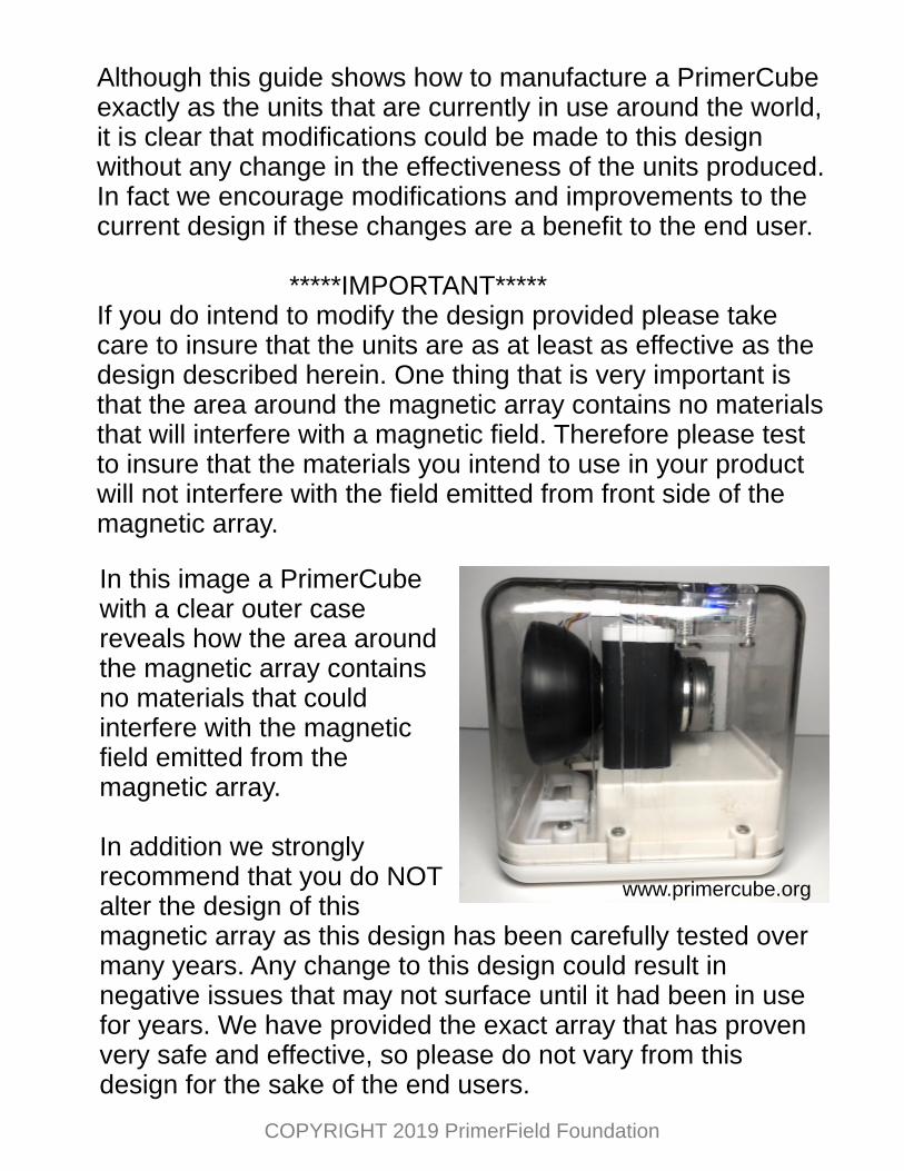
*****IMPORTANT*****If you do intend to modify the design provided please take care to insure that the units are as at least as effective as the design described herein. One thing that is very important is that the area around the magnetic array contains no materials that will interfere with a magnetic field. Therefore please test to insure that the materials you intend to use in your product will not interfere with the field emitted from front side of the magnetic array.
In this image a PrimerCube with a clear outer case reveals how the area around the magnetic array contains no materials that could interfere with the magnetic field emitted from the magnetic array.
In addition we strongly recommend that you do NOT alter the design of this magnetic array as this design has been carefully tested over many years. Any change to this design could result in negative issues that may not surface until it had been in use for years. We have provided the exact array that has proven very safe and effective, so please do not vary from this design for the sake of the end users.
www.primercube.org
COPYRIGHT 2019 PrimerField Foundation
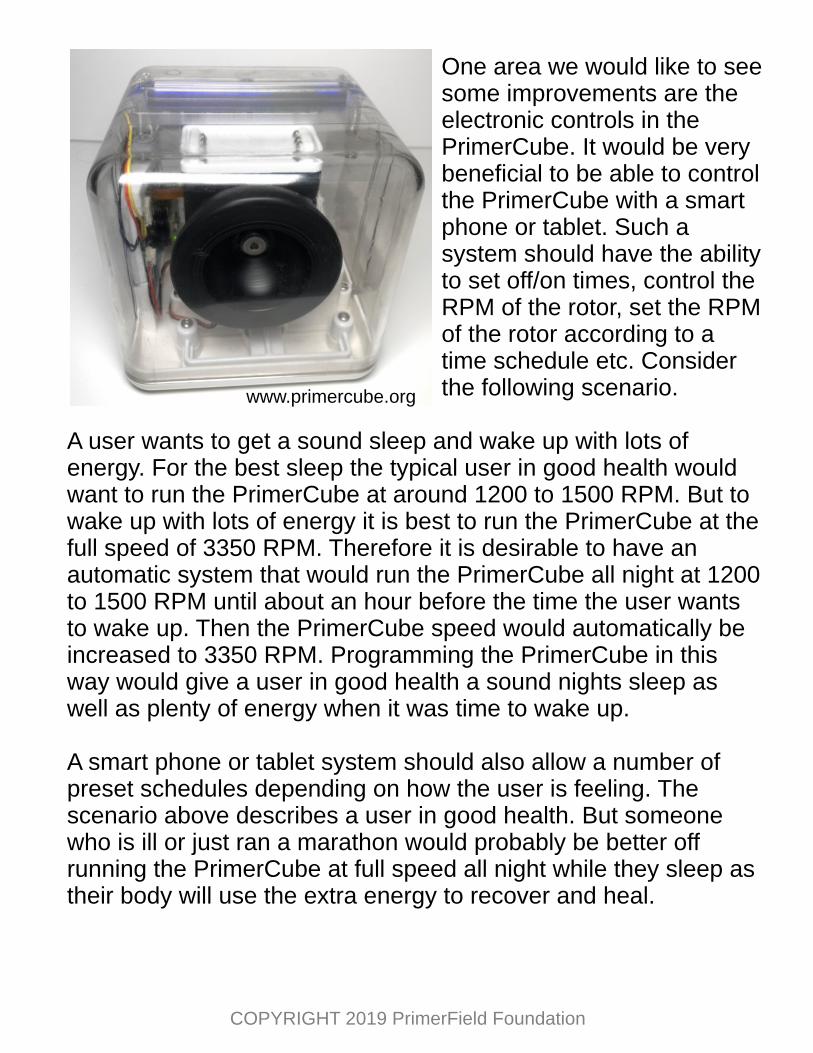
One area we would like to see some improvements are the electronic controls in the PrimerCube. It would be very beneficial to be able to control the PrimerCube with a smart phone or tablet. Such a system should have the ability to set off/on times, control the RPM of the rotor, set the RPM of the rotor according to a time schedule etc. Consider the following scenario.
A user wants to get a sound sleep and wake up with lots of energy. For the best sleep the typical user in good health would want to run the PrimerCube at around 1200 to 1500 RPM. But to wake up with lots of energy it is best to run the PrimerCube at the full speed of 3350 RPM. Therefore it is desirable to have an automatic system that would run the PrimerCube all night at 1200 to 1500 RPM until about an hour before the time the user wants to wake up. Then the PrimerCube speed would automatically be increased to 3350 RPM. Programming the PrimerCube in this way would give a user in good health a sound nights sleep as well as plenty of energy when it was time to wake up.
A smart phone or tablet system should also allow a number of preset schedules depending on how the user is feeling. The scenario above describes a user in good health. But someone who is ill or just ran a marathon would probably be better off running the PrimerCube at full speed all night while they sleep as their body will use the extra energy to recover and heal.
www.primercube.org
COPYRIGHT 2019 PrimerField Foundation
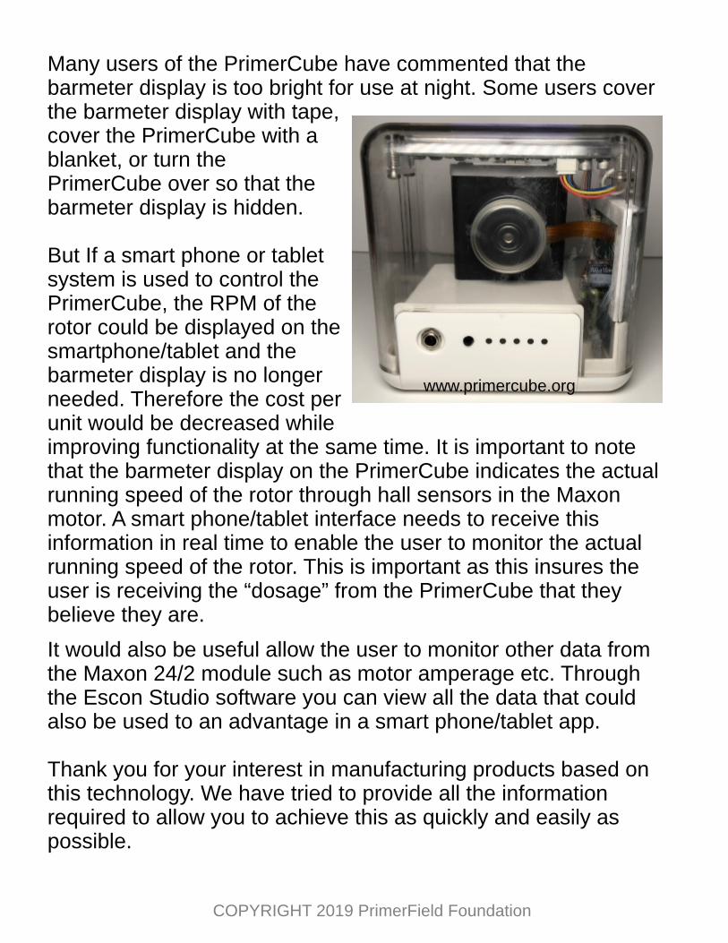
Many users of the PrimerCube have commented that the barmeter display is too bright for use at night. Some users cover the barmeter display with tape, cover the PrimerCube with a blanket, or turn the PrimerCube over so that the barmeter display is hidden.
But If a smart phone or tablet system is used to control the PrimerCube, the RPM of the rotor could be displayed on the smartphone/tablet and the barmeter display is no longer needed. Therefore the cost per unit would be decreased while improving functionality at the same time. It is important to note that the barmeter display on the PrimerCube indicates the actual running speed of the rotor through hall sensors in the Maxon motor. A smart phone/tablet interface needs to receive this information in real time to enable the user to monitor the actual running speed of the rotor. This is important as this insures the user is receiving the “dosage” from the PrimerCube that they believe they are.
It would also be useful allow the user to monitor other data from the Maxon 24/2 module such as motor amperage etc. Through the Escon Studio software you can view all the data that could also be used to an advantage in a smart phone/tablet app.
Thank you for your interest in manufacturing products based on this technology. We have tried to provide all the information required to allow you to achieve this as quickly and easily as possible.