62
PRIMERGY .com Operating Manual PRIMERGY econel 20 English
| Date post: | 09-Apr-2018 |
| Category: |
Documents |
| Upload: | truongliem |
| View: | 218 times |
| Download: | 5 times |
PRIMERGY.com Operating Manual
PRIMERGY econel 20E n g l i s h

Are there ...
... any technical problems or other questions which you would like to be clarified?
Please contact:� your sales partner� your sales outlet
Further information can be found in the "Safety, Warranty and Ergonomics" booklet.
The latest information on our products, tips, updates, etc., can be found on the internet under:http://www.fujitsu-siemens.com


Herausgegeben von/Published byFujitsu Siemens Computers GmbH
Bestell-Nr./Order No.: A26361-K831-Z101-1-7619AG 02/02
A26361-K831-Z101-1-7619
PRIMERGY econel 20 OPERATING MANUAL

PRIMERGY econel 20
Operating Manual
Introduction
Important notes
Preparing for Use
Operation
Troubleshooting and tips
System expansions
Technical data
Index
January 2002 edition
Microsoft, MS, MS-DOS, Windows, and Windows NT are registered trademarks of MicrosoftCorporation.
VESA and DPMS are trademarks of Video Electronics Standards Association.
PS/2 is a registered trademark of International Business Machines, Inc.
Pentium is a registered trademark of Intel Corporation, USA.
Acrobat Reader is a trademark of Adobe Systems Incorporated.
All other trademarks referenced are trademarks or registered trademarks of their respectiveowners, whose protected rights are acknowledged.
Copyright � Fujitsu Siemens Computers GmbH 2001
All rights, including rights of translation, reproduction by printing, copying or similar methods,in part or in whole, are reserved.
Offenders will be liable for damages.
All rights, including rights created by patent grant or registration of a utility model or design,are reserved.
Delivery subject to availability. Right of technical modification reserved.
This manual was produced bycognitas. Gesellschaft für Technik-Dokumentation mbHwww.cognitas.de

A26361-K831-Z101-1-7619
ContentsIntroduction .....................................................................................................................................1Notational conventions ......................................................................................................................1
Important notes ...............................................................................................................................3Safety ................................................................................................................................................3Manufacturer’s notes .........................................................................................................................3
Energy saving............................................................................................................................3Disposal and recycling...............................................................................................................4CE marking................................................................................................................................4FCC Class B Compliance Statement .........................................................................................5
Transporting the server......................................................................................................................6Cleaning the server............................................................................................................................6
Preparing for Use ............................................................................................................................7Unpacking and Checking the Delivery ...............................................................................................7Steps for initial setup .........................................................................................................................7Setting up the server .........................................................................................................................8Connect the monitor, mouse and keyboard .......................................................................................8
Connecting the keyboard ...........................................................................................................8Connecting the mouse...............................................................................................................9
Connecting the server to the mains voltage.....................................................................................10Initial switch-on: Software will be installed .......................................................................................12
Switching on monitor and server..............................................................................................12Installing the software ..............................................................................................................14
Connecting external devices............................................................................................................15Connections on the system unit ...............................................................................................16Connecting external devices to the serial port..........................................................................17Connecting external devices to the parallel port.......................................................................17
Operation .......................................................................................................................................19Switching on the server ...................................................................................................................19Switching off the server ...................................................................................................................20Indicators on the system unit ...........................................................................................................21Keyboard .........................................................................................................................................22
Important keys and key combinations......................................................................................22Working with floppy disks ................................................................................................................24Settings in BIOS Setup....................................................................................................................24Property and data protection............................................................................................................25
Anti-theft protection..................................................................................................................25Access protection under Windows ...........................................................................................25BIOS Setup security functions .................................................................................................26Access protection with SICRYPT server Lock .........................................................................26
Troubleshooting and tips..............................................................................................................29Installing new software ....................................................................................................................29Power-on indicator remains unlit after you have switched on your device........................................29
The screen stays blank............................................................................................................30No mouse pointer displayed on the screen ......................................................................................31The floppy disk cannot be read or written ........................................................................................31Time and/or date is not correct ........................................................................................................32Error messages on the screen.........................................................................................................32Restoring the hard disk contents .....................................................................................................32Tips .................................................................................................................................................32

Contents
A26361-K831-Z101-1-7619
System expansions....................................................................................................................... 35Information about boards ........................................................................................................ 35
Opening the system unit ................................................................................................................. 36Assembling the system unit ............................................................................................................ 37Installing and removing a board ...................................................................................................... 37
Installing a board..................................................................................................................... 38Removing a board................................................................................................................... 39
Installing and removing drives......................................................................................................... 40Installing an accessible drive................................................................................................... 40Removing an accessible drive................................................................................................. 42Changing the floppy disk drive ................................................................................................ 43Replacing a hard disk drive ..................................................................................................... 45
Extensions to the system board ...................................................................................................... 47Upgrading main memory ......................................................................................................... 47Replacing lithium battery ......................................................................................................... 47Replacing processor................................................................................................................ 48
Technical data ............................................................................................................................... 49
Index .............................................................................................................................................. 51

A26361-K831-Z101-1-7619 1
IntroductionThis operating manual tells you how to put your server into operation and how to operate it in dailyuse. The Operating Manual applies for all configuration levels. Depending on the configuration levelchosen some of the hardware components described may not be available on your server. Pleaseobserve the notes on your operating system.
You can incorporate operable drives (for example DAT drive) as well as other boards.
Depending on the configuration selected, the operating system is preinstalled on your hard disk (e.g.Windows 2000).
Your server has a number of security features to ensure that no unauthorised persons can accessyour data, for example, you can activate a screen saver with password protection. For example, youcan activate a screen saver with password protection. The security functions in the BIOS Setup alsoallow you to protect your data by means of passwords. Systems with a SmartCard reader offeradditional protection.
Further information on this server is provided:
� in the "Safety, Warranty and Ergonomics" booklet� in the operating manual for the monitor� in the technical manual for the system board� in the "BIOS Setup" manual� in your operating system documentation� in the information files (e.g. *.TXT, *.DOC, *.WRI, *.HLP)
i
Some of the manuals listed can be found on the "Drivers & Utilities" CD provided withyour computer. These manuals can be read and printed with Acrobat Reader, alsocontained on the "Drivers & Utilities" CD.
Notational conventions The meanings of the symbols and fonts used in this manual are as follows:
! indicates information which is important for your health or for preventing physical damage.
i
indicates important information which is required to use the system properly.
Ê Text which follows this symbol describes activities that must be performed in the order shown.
Text in this typeface indicates screen outputs.
Text in italics indicates commands or menu items.
"Quotation marks" indicate names of chapters or terms.


A26361-K831-Z101-1-7619 3
Important notes In this chapter you will find information regarding safety which is essential to take note of whenworking with your server. The manufacturer's notes contain helpful information on your server.
Safety
! Pay attention to the information provided in the "Safety, Warranty and Ergonomics"booklet and to the following notes.
During installation and before operating the device, please observe the instructions onenvironmental conditions in the chapter entitled "Technical data" as well as theinstructions in the chapter "Preparing for Use".
Please check whether the device is correctly set for the local power supply (see"Preparing for Use" chapter).
The main switch and the ON/OFF switch do not disconnect the system unit from themains voltage. To completely disconnect the mains voltage, remove the power plug fromthe grounded mains outlet.
Replace the lithium battery on the system board in accordance with the instructions in the"System expansions - Replacing lithium battery" chapter.
Caution: components in the system can get very hot.
Manufacturer’s notesKeep this operating manual together with your device. If you pass on the device to third parties, youshould include this manual.
Energy savingWhen the server is delivered, some energy-saving functions are already set (see the technicalmanual for the system board or the "BIOS Setup" manual).
� If you are not using your server, switch it off.
� In the BIOS Setup you may set further energy-saving functions for the server (see the technicalmanual for the system board or in the manual "BIOS Setup").
� Depending on the operating system, you can set additional power-management features.
Energy saving under Windows 9x
The Screen Saver tab allows you to set further energy saving functions for your screen. Select thefollowing item in the menu: Start - Settings - Control Panel - Display - Display Properties - Screen Saver -Energy saving features of monitor.
With the default setting Control Panel - Power - Advanced additional energy saving features ofWindows 9x are available.

Important notes Manufacturer’s notes
4 A26361-K831-Z101-1-7619
Energy saving under Windows 2000
The Screen Saver tab allows you to set energy-saving functions for your screen. Select the followingitem in the menu: Start - Settings - Control Panel - Display - Display Properties - Screen Saver - Energysaving features of monitor.
With the default setting Control Panel - Power Options - Advanced additional power managementfeatures of Windows 2000 are available.
Disposal and recycling This device has been manufactured to the highest possible degree from materials which can berecycled or disposed of in a manner that is not environmentally damaging. The device may be takenback after use to be recycled, provided that it is returned in a condition that is the result of normaluse. Any components not reclaimed will be disposed of in an environmentally acceptable manner.
Devices protected by a 36 month warranty from Fujitsu Siemens meet therequirements of the eco-label "Blauer Engel". The warranty starts on the dayof delivery (sale date) by Fujitsu Siemens Computers or a Fujitsu Siemensaffiliate.
The repair of a device displaying the eco-label is secured for at least 5years from the date of purchase.
Further information about eco-label products can be found on the Internetunder www.blauer-engel.de.
Do not throw lithium batteries into the household waste. They must be disposed of in accordancewith local regulations concerning special waste.
If you have any questions about disposal of the batteries or system, please contact your local salesoutlet or:
Fujitsu Siemens Computers GmbH Recyclingcenter D-33106 Paderborn
Tel.: +49 (0) 5251 81 80 10 Fax: +49 (0) 5251 81 80 15
CE marking
The shipped version of this device complies with the requirements of the EEC directives89/336/EEC "Electromagnetic compatibility" and 73/23/EEC "Low voltage directive".

Manufacturer’s notes Important notes
A26361-K831-Z101-1-7619 5
FCC Class B Compliance StatementThe following statement applies to the products covered in this manual, unless otherwise specifiedherein. The statement for other products will appear in the accompanying documentation.
NOTE:
This equipment has been tested and found to comply with the limits for a "Class B" digital device,pursuant to Part 15 of the FCC rules and meets all requirements of the Canadian Interference-Causing Equipment Regulations. These limits are designed to provide reasonable protection againstharmful interference in a residential installation. This equipment generates, uses and can radiateradio frequency energy and, if not installed and used in strict accordance with the instructions, maycause harmful interference to radio communications. However, there is no guarantee thatinterference will not occur in a particular installation. If this equipment does cause harmfulinterference to radio or television reception, which can be determined by turning the equipment offand on, the user is encouraged to try to correct the interference by one or more of the followingmeasures:
� Reorient or relocate the receiving antenna.� Increase the separation between equipment and the receiver.� Connect the equipment into an outlet on a circuit different from that to which the receiver is
connected.� Consult the dealer or an experienced radio/TV technician for help.
Fujitsu Siemens Computers GmbH is not responsible for any radio or television interference causedby unauthorised modifications of this equipment or the substitution or attachment of connectingcables and equipment other than those specified by Fujitsu Siemens Computers GmbH. Thecorrection of interference caused by such unauthorised modification, substitution or attachment willbe the responsibility of the user.
The use of shielded I/O cables is required when connecting this equipment to any and all optionalperipheral or host devices. Failure to do so may violate FCC rules.

Important notes Transporting the server
6 A26361-K831-Z101-1-7619
Transporting the server
! Transport all parts separately in their original packaging or in a packaging which protectsthem from knocks and jolts, to the new site. Do not unpack them until all transportationmanoeuvres are completed.
Never drop the monitor (risk of implosion)!
Cleaning the server
! Turn off all power and equipment switches and remove the power plug from the mainssupply.
Do not clean any interior parts yourself, leave this job to a service technician.
Do not use any cleaning agents that contain abrasives or may corrode plastic.
Ensure that no liquid enters the system.
Ensure that the ventilation areas of the system unit and the monitor are free.
Cleaning the system unit and the monitor
Wipe the system unit and monitor casing with a dry cloth. If particularly dirty, use a cloth that hasbeen moistened in mild domestic detergent and then carefully wrung out.
Cleaning the keyboard and the mouse
Use disinfectant wipes to clean the keyboard and the mouse.
The mouse mechanism and the mouse ball can be cleaned by removing the retaining ring on theunderside of the mouse.
i Additional information can be found in the documentation for your keyboard and mouse.

A26361-K831-Z101-1-7619 7
Preparing for Use
! Please take note of the safety information in the "Important notes" chapter.
Unpacking and Checking the DeliveryIt is recommended not to throw away the original packaging material! It may be required forreshipment at some later date.
Ê Unpack all the individual parts.
Ê Check the delivery for damage incurred during transportation.
Ê Check whether the delivery agrees with the details in the delivery note.
Should you discover that the delivery does not correspond to the delivery note, notify your localsales outlet immediately.
Steps for initial setupFirst-time setup includes the connection of the monitor, mouse and keyboard to the system unit andthe setup of the supplied software.
iExternal devices
If you have received other devices in addition to your server (e.g. a printer or a modem),do not connect these until after the initial installation. The following sections contain adescription of how to connect these external devices: "Connecting external devices to theserial port" and "Connecting external devices to the parallel port".
Drives and boards
If you have received drives or boards with your server, please do not install them untilafter first-time setup. How to install drives and boards is described in the chapter "Systemexpansions".
Perform the following steps in the prescribed order:
1. Decide where you are going to use the server, and then set it up.
2. Connect the monitor, mouse and keyboard to the server.
3. Check the rated voltage of the server and connect it to the mains voltage.
4. Switch the server on and follow the instructions on the screen.
Preparing for Use Setting up the server
8 A26361-K831-Z101-1-7619
Setting up the server
! When installing your server, give consideration to the recommendations and safety notesin the "Safety, Warranty and Ergonomics" booklet.
Set up the server only in its correct orientation. The points to observe are illustrated on thefollowing pages.
We recommend that you place your equipment on a surface with good anti-slip qualities.In view of the multitude of different finishes and varnishes used on furniture, it is possiblethat the rubber feet of the devices will mark the surface they stand on.
Do not expose the server to extreme environmental conditions (see chapter "Technicaldata") and protect it from dust, humidity and heat.
Provide at least 200 mm of clearance on the left, in front of and behind the ventilator areaof the system unit to ensure adequate ventilation. Do not cover the ventilation areas of themonitor and the system unit.
Do not place several system units one above the other.
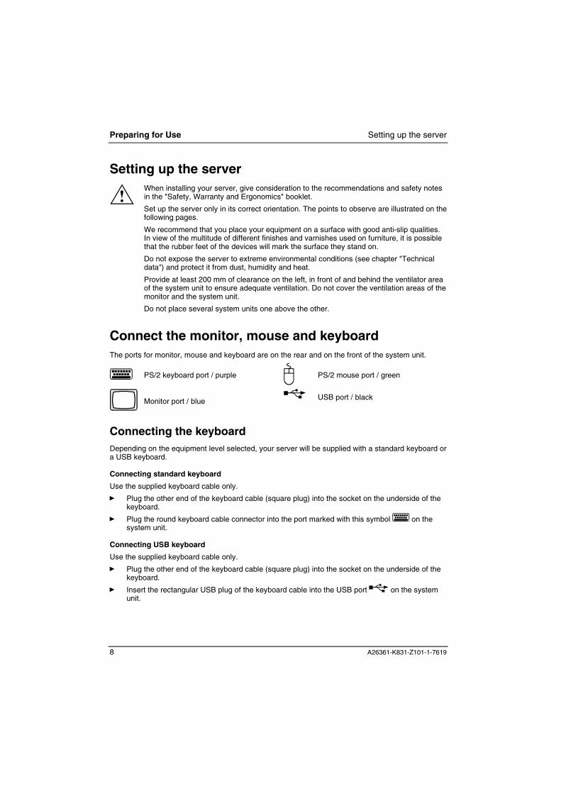
Connect the monitor, mouse and keyboardThe ports for monitor, mouse and keyboard are on the rear and on the front of the system unit.
PS/2 keyboard port / purple PS/2 mouse port / green
Monitor port / blue USB port / black
Connecting the keyboardDepending on the equipment level selected, your server will be supplied with a standard keyboard ora USB keyboard.
Connecting standard keyboard
Use the supplied keyboard cable only.
Ê Plug the other end of the keyboard cable (square plug) into the socket on the underside of thekeyboard.
Ê Plug the round keyboard cable connector into the port marked with this symbol on thesystem unit.
Connecting USB keyboard
Use the supplied keyboard cable only.
Ê Plug the other end of the keyboard cable (square plug) into the socket on the underside of thekeyboard.
Ê Insert the rectangular USB plug of the keyboard cable into the USB port on the systemunit.

Connect the monitor, mouse and keyboard Preparing for Use
A26361-K831-Z101-1-7619 9
Connecting the mouseDepending on the equipment level selected, your server will be supplied with a PS/2 mouse or aUSB mouse.
Connecting a PS/2 mouse
Ê Connect the PS/2 mouse to the PS/2 mouse port on the system unit.
Connecting USB mouse
Ê Connect the USB mouse to the USB port on the system unit.
i If you do not attach a mouse at the PS/2 mouse port , you can disable the mousecontroller in the BIOS Setup in order to free the IRQ12 for a different application.

Preparing for Use Connecting the server to the mains voltage
10 A26361-K831-Z101-1-7619
Connecting the server to the mains voltage
100 V - 127 V
200 V - 240 V
100 V - 127 V 200 V - 240 V
a a
a = Notch for inserting the screwdriver
If the power supply of your server does not have a slide-in or plug-in element for setting the ratedvoltage, then your system automatically sets itself to the local rated voltage. If you have a serverwith a slide-in or plug-in element, then you must match the set rated voltage to the local ratedvoltage.
Ê Check the voltage setting.
! Devices with main power switch:
The value indicated with an arrow must be compatible with the local rated voltage:115 = 100 V to 127 V 230 = 200 V to 240 V
If the voltage setting is incorrect, then lift out the manual voltage adjuster with ascrewdriver (1), turn it to the required setting and reinsert it.
Devices without main power switch:
The visible value must agree with the local mains voltage:115 = 100 V to 127 V 230 = 200 V to 240 V
If an incorrect mains voltage is set, push the slide switch all the way into the otherpossible position with a pointed object.

Connecting the server to the mains voltage Preparing for Use
A26361-K831-Z101-1-7619 11
21
Ê Plug the system unit's power cable into the system unit (1) and then into the grounded mainsoutlet (2).

Preparing for Use Initial switch-on: Software will be installed
12 A26361-K831-Z101-1-7619
Initial switch-on: Software will be installedIf the server is connected to a network, the network protocol is required as well as the user andserver details. Contact your network administrator if you have any questions about these settings.
When you switch on your server for the first time, the supplied software is installed and configured.You should plan some time for this, as this process must not be interrupted.
! Once the installation has been started the server must not be switched off!
During installation the server may only be rebooted when you are requested to do so!
Otherwise the installation will be not be performed correctly. If a fault occurs during theinstallation, the contents of the hard disk must be completely restored.
You may need the licence number for Windows during the installation. This number is located on asticker on your server.
Switching on monitor and serverÊ Switch the monitor on (see the operating manual for the monitor).
Ê Switch the server on. To do this, follow the instructions below.
iDepending on the version, your server is equipped with a main power switch on the backof the casing in addition to the power button on the front. This differentiates between theways to switch on both server versions.

Initial switch-on: Software will be installed Preparing for Use
A26361-K831-Z101-1-7619 13
Switching on server with devices with main power switch
0 I1
3
2
1 = Main power switch2 = Power button3 = Power-on indicator
0 = server is switched off I = server is ready-to-operate
Ê Switch the server on with the main power switch on the back panel.
Ê If the power-on indicator lights orange or flashes green/orange, press the power button on thefront of the casing.
The power-on indicator lights green and the server is started.

Preparing for Use Initial switch-on: Software will be installed
14 A26361-K831-Z101-1-7619
Switching on server with devices without main power switch
1
2
1 = Power button 2 = Power-on indicator
Ê If the power-on indicator lights orange or flashes green/orange, press the power button on thefront of the casing.
The power-on indicator lights green and the server is started.
Installing the softwareÊ During installation, follow the instructions on screen.
Consult the operating system manual if there is anything unclear about the requested input data.
iYou will find further information about the system, drivers, utilities, updates, manuals etc.on the "Drivers & Utilities" CD supplied.

Connecting external devices Preparing for Use
A26361-K831-Z101-1-7619 15
Connecting external devices
! Do not connect or disconnect cables during a thunderstorm.
Always take hold of the actual plug. Never unplug a cable by pulling the cable itself.
Connect and disconnect the cables in the order described below.
With the exception of USB devices, always remove all power plugs before connectingexternal devices!
Read the documentation on the external device before connecting it.
Connecting cables
� Turn off all power and equipment switches.
� Pull all power plugs out of grounded mains outlets.
� Connect all cables at the system unit and peripherals. You must observe the informationprovided in the chapter "Important notes".
� Plug all data communication cables into the utility sockets.
� Plug all power cables into the grounded mains outlets.
Disconnecting cables
� Turn off all power and equipment switches.
� Pull all power plugs out of grounded mains outlets.
� Unplug all data communication cables from the utility sockets.
� Disconnect all cables from the system unit and peripherals.
iUSB devices are hot-pluggable. This allows cables from USB devices to be connectedand disconnected with the system switched on.
Additional information can be found in the documentation for the USB devices.

Preparing for Use Connecting external devices
16 A26361-K831-Z101-1-7619
Connections on the system unitThe ports for external devices are on the rear and on the front of the system unit. The portsavailable on your server depend on the configuration level you have selected. The standard portsare marked with the symbols shown below (or similar). Exact details of the position of the ports aresupplied in the technical manuals for the boards. Keyboard port / purple
PS/2 mouse port / green
1
Serial interface 1 / turquoise
2
Serial interface 2 / turquoise
Monitor port / blue
Parallel interface / Printer / burgundy
Headphones port / orange
Microphone jack (mono) / pink
Audio output (Line out) / lime green
Audio input (Line in) / light blue
Game port / gold
SCSI connection
USB - Universal Serial Bus / black LAN LAN connector
i
Some of the devices that you connect require special drivers (see the operating systemand device documentation).

Connecting external devices Preparing for Use
A26361-K831-Z101-1-7619 17
Connecting external devices to the serial port
External devices can be connected to the serial port (e.g. a modem).
Ê Connect the data cable to the external device.
Ê Connect the data cable to the serial port .
For an exact description of how to connect external devices to the serial port , please refer to thedevice documentation.
iSettings of the serial port
If you need to change the settings of the serial port (e.g. address, interrupt), you can doso in the BIOS Setup. The settings for the port are described in the technical manual forthe system board or in the "BIOS Setup" manual.
Device drivers
The devices connected to the serial port require drivers. Your operating system alreadyincludes many drivers. Nevertheless, if the driver you need is not on the hard disk, pleaseinstall it from the data carrier supplied with the device or with the application programme.
Connecting external devices to the parallel port
External devices can be connected to the parallel port (e.g. a printer).
Ê Connect the data cable to the external device.
Ê Connect the data cable to the parallel port .
For an exact description of how to connect external devices to the parallel port, please see thedevice documentation.
iSettings of the parallel port
If you need to change the settings of the parallel port (e.g. address, interrupt), you can doso in the BIOS Setup. The settings for the port are described in the technical manual forthe system board or in the "BIOS Setup" manual.
Device drivers
The devices connected to the parallel port require drivers. Your operating system alreadyincludes many drivers. Nevertheless, if the driver you need is not on the hard disk, pleaseinstall it from the data carrier supplied with the device or with the application programme.


A26361-K831-Z101-1-7619 19
Operation
Switching on the serverÊ Switch the monitor on (see the operating manual for the monitor).
On devices with main power switch
Ê Switch the server on with the main power switch on the back panel.
Ê If the power-on indicator lights orange or flashes green/orange, press the power button on thefront of the casing.
The power-on indicator lights green and the server is started.
iIf you have assigned the system password, you must enter this when requested to do soin order to start the operating system.
On devices without main power switch
Ê If the power-on indicator lights orange or flashes green/orange, press the power button on thefront of the casing.
The power-on indicator lights green and the server is started.
iIf you have assigned the system password, you must enter this when requested to do soin order to start the operating system.

Operation Switching off the server
20 A26361-K831-Z101-1-7619
Switching off the server
On devices with main power switch
Ê Shut down the operating system properly. For Windows: select Shut Down from the Start menu.
Ê If the operating system does not automatically switch off the server, switch the server to ready-to-operate by pressing the power button or turn it off by pressing the main power switch whenrequested to do so.
If the server is ready-to-operate, the power-on indicator is illuminated orange. The server usesminimal energy.
When the server is switched off with the main power switch, the power-on indicator goes off afterapprox. 15 seconds. The server no longer uses any power.
! The main power switch and the power button do not disconnect the server from the mainsvoltage. To completely disconnect the mains voltage, remove the power plug from thesocket.
Ê Switch the monitor off (see the operating manual for the monitor).
On devices without main power switch
Ê Shut down the operating system properly. For Windows: select Shut Down from the Start menu.
Ê If the operating system does not automatically switch the server off, turn the server to ready-to-operate when requested to do so by pressing the power button.
If the server is ready-to-operate, the power-on indicator is illuminated orange. The server usesminimal energy.
! The power button does not disconnect the server from the mains voltage. To completelydisconnect the mains voltage, remove the power plug from the socket.
Ê Switch the monitor off (see the operating manual for the monitor).
Placing a server (with soft power off function) in a ready-to-operate state by means ofsoftware
With the soft power off function the server automatically switches off (standby) or switches into theenergy-saving mode after the operating system is shut down. Requirements: Your system mustsupport switching off with software and this functionality must be enabled in BIOS Setup. The softpower off software may also need to be installed on Windows NT systems.
You can also switch your server into the standby mode via the DeskView software with the DeskOffprogramme.

Indicators on the system unit Operation
A26361-K831-Z101-1-7619 21
Indicators on the system unit
4
3
5
1 2
1 = Floppy disk indicator2 = CD-ROM indicator3 = Hard disk indicator
4 = Power-on indicator5 = Power button
1 - Floppy disk indicator
The indicator lights up when the floppy disk drive of the system unit is accessed. You may onlyremove the floppy disk when the indicator is unlit.
2 - CD-ROM indicator
The indicator lights up when the CD-ROM drive of the system unit is accessed. You may onlyremove the CD when the indicator is dark.
3 - Hard disk indicator
The indicator lights up when the hard disk drive of the system unit is accessed.
4 - Power-on indicator
� green:The system unit is on.
� orange:The system unit is ready-to-operate.In this mode the server consumes very little power and can be switched on with the powerbutton.
� flashing green/orange:The indicator only flashes on systems which support the ACPI function (AdvancedConfiguration and Power Management Interface).The system unit is in the energy-saving mode (standby). After being switched on with thepower button, the server returns to the state it was in before the energy-saving mode.

Operation Keyboard
22 A26361-K831-Z101-1-7619
! In an energy-saving mode the server must not be switched off with the mainpower switch (if present) or disconnected from the mains, as this may result indata loss.
5 - ON/OFF switch
Switches the server on or off. With Windows 98 with ACPI or with Windows 2000 you can setadditional functions of the ON/OFF switch in the Control Panel (Power management).
Keyboard
1
3 4 5
2
1 = Function keys2 = Power button (optional)3 = alphanumeric keypad
4 = Cursor control keys5 = numeric keypad (calculator keypad)
Important keys and key combinationsThe following description of keys and key combinations refers to MS Windows. Details of other keysand key combinations can be found in the documentation of the relevant application programme.
ON/OFF switchDepending on the setting in the BIOS setup, the system can be switched on or offwith this switch. With Windows 98 with ACPI or with Windows 2000 you can setadditional functions of the power button in the Control Panel.
On some keyboards the power button can only be used with ACPI. Otherwise thekey is inoperative.
Enter keyconfirms or starts the marked selection. The enter key is also referred to as the"Return" key.

Keyboard Operation
A26361-K831-Z101-1-7619 23
Start keycalls up the Windows Start menu.
Menu keyinvokes the menu for the marked item.
Shift keyenables upper-case letters and the upper key symbols to be used.
Alt GrAlt Gr (e.g. German keyboard)produces a character shown on the right-hand side of a key (e.g. the character "\"on the key [ß]).
E Euro keyenables the output of the euro symbol.
NumLock
Num Lock keyby pressing the Num Lock key you switch between the upper- and lower-case levelsof the calculator keypad.When the Num Lock indicator is lit the digit and comma keys are active.When the Num Lock indicator is not lit the cursor control functions are active in theNumeric keypad.
CtrlCtrl keystarts key combination actions.

Operation Working with floppy disks
24 A26361-K831-Z101-1-7619
Working with floppy disks
iFollow the instructions supplied by the vendor of the floppy disks.Never clean the floppy disk drives with cleaning disks. Any attempt would destroy theread/write head in the disk drive within 20 seconds.
32
1
5
64
7
1 = Insertion direction2 = Label area3 = Write protection switch for a 720 KB or a 1.44 MB floppy disk4 = Identification of a 1.44 MB floppy disk or write protect switch on a 120 MB floppy disk5 = Eject button for inserted floppy disks6 = Disk is write-protected7 = Disk is not write-protected
Ê To insert a floppy disk, push it into the drive in the insertion direction until it engages. The labelshould be facing upward.
Ê To remove the floppy disk, press the eject button (5).
The write-protect switch enables you to protect the data on the floppy disk from inadvertentoverwriting or deletion.
Ê To protect the data on the floppy disk from being overwritten, push the write-protect switch toposition (6). The hole is now visible.
Ê To remove write protection, push the switch to position (7). The hole is now covered.
Settings in BIOS SetupThe BIOS Setup menu allows you to set your hardware configuration and system functions. When theserver is delivered, the default entries are valid (see Technical Manual for the system board or themanual "BIOS Setup"). You may customise these settings to your requirements in the BIOS Setup.
The Technical Manual for the system board shows you how to call and operate BIOS Setup. Themenus and setting options provided by the BIOS Setup are also described in detail.
Property and data protection Operation
A26361-K831-Z101-1-7619 25
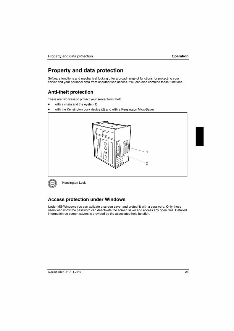
Property and data protectionSoftware functions and mechanical locking offer a broad range of functions for protecting yourserver and your personal data from unauthorised access. You can also combine these functions.
Anti-theft protectionThere are two ways to protect your server from theft:
� with a chain and the eyelet (1)
� with the Kensington Lock device (2) and with a Kensington MicroSaver
1
2
Kensington Lock
Access protection under WindowsUnder MS-Windows you can activate a screen saver and protect it with a password. Only thoseusers who know the password can deactivate the screen saver and access any open files. Detailedinformation on screen savers is provided by the associated help function.

Operation Property and data protection
26 A26361-K831-Z101-1-7619
BIOS Setup security functionsThe Security menu in BIOS Setup offers you various options for protecting your personal data againstunauthorised access, e.g.:
� Preventing unauthorised BIOS Setup entry� Preventing unauthorised system access� Preventing unauthorised access to the settings of boards with their own BIOS� Preventing system booting from the diskette drive� Activating virus warnings� Preventing unauthorised writing of diskettes� Protecting BIOS from being overwritten� Protecting the server from being switched on by an external device
You can also combine these functions.
You will find a detailed description of the Security menus and how to assign passwords in thetechnical manual for the system board or in the "BIOS Setup" manual.
Access protection with SICRYPT server LockWith SICRYPT server Lock you can protect your system from unauthorised booting. Then a systemcan only be booted when the user inserts a valid SmartCard in the SmartCard reader and entershis/her personal code number (PIN). To use server Lock you require the following components:
� External or internal SmartCard reader
� server Lock installed (see manual "BIOS Setup")
� SICRYPT SmartCard
iThere are two different SmartCards - the Admin SmartCard and the User SmartCard.These differ in their memory capacity. In addition to the access permissions, you can alsosave other safety options on the Admin SmartCard (e.g. fingerprints with the Smarty 2software).
server Lock controls access to your server. When a SmartCard is initialised, permissions areassigned for system access (system, setup, system+setup, admin). You can configure severalSmartCards for one system and initialise them with different permissions.
In this way users can be divided into user groups. Users of a user group use SmartCards with thesame permissions.
Additional instructions for server Lock
iDo not use server Lock on systems controlled by tele-maintenance. If a SmartCard isinserted and the User PIN must be entered, an automatic system boot is blocked.For example, this is the case with "Wake On LAN", or when software is to beinstalled via the network that requires a system reboot.
After you have initialised the first SmartCard, the entry server-Lock can no longer bedeactivated (Disabled) in the BIOS Setup.
If you also want to use other security software in addition to server Lock (e.g.SmartGuard Pro), please read the documentation on your security softwarebeforehand.
Property and data protection Operation
A26361-K831-Z101-1-7619 27
server Lock permissions
You can initialise a SmartCard with one of the following permissions:
System The system starts following entry of the user PIN. You can change the userPIN.
Setup You can open and change the BIOS Setup and change the user PIN.
System+Setup The system starts following entry of the user PIN. You can open and changethe BIOS Setup and change the user PIN.
Admin The system starts following entry of the user PIN. You can change the userPIN an the administrator PIN, unlock locked SmartCards, open and change theBIOS Setup and generate additional SmartCards for this system.
For instructions on how to install and operate SICRYPT server Lock, and how to initialiseSmartCards, see the "BIOS Setup" manual.
Operating the SmartCard reader
� Operating the internal SmartCard reader
You can switch on the server by inserting your SmartCard. If the SmartCard reader has beenreleased, the SmartCard reader indicator on the front of the server flashes green.
� Operating the external SmartCard reader
After the server is switched on, you will be prompted to insert your SICRYPT SmartCard.

A26361-K831-Z101-1-7619 29
Troubleshooting and tips
! Take careful note of the safety warnings in the "Safety, Warranty and Ergonomics"booklet and in the "Preparing for Use" chapter, when you connect or disconnect cables.
If a fault occurs, try to correct it as described:� in this chapter� in the documentation of the connected devices� in the help systems of the software used.
If you fail to correct the problem, proceed as follows:
Ê Switch the server off.
Ê Make a note of the steps and the circumstances that led to the fault.
Ê Make a note of any error messages displayed.
Ê Note the ID number of your device.
Ê Contact your sales outlet or our customer service centre.
Installing new softwareWhen installing programmes or drivers, important files may be overwritten and modified. To be ableto access the original data in the event of any problems following installation, you should backupyour hard disk prior to installation.
Power-on indicator remains unlit after you haveswitched on your deviceThis may be due to the following:
The mains voltage supply is faulty
Ê Check that the power cable is plugged properly into the system unit and grounded mains outlet.
Ê Switch the server on at the power switch.
Internal power supply overloaded
Ê Disconnect the power cable of the system unit from the grounded mains outlet.
Ê Wait for a moment.
Ê Plug the power cable into the grounded mains outlet again.
Ê Switch the server on at the power switch.

Troubleshooting and tipsPower-on indicator remains unlit after you have switched on your device
30 A26361-K831-Z101-1-7619
The screen stays blankIf your screen remains blank this may be due to the following:
Monitor is switched off
Ê Switch your monitor on.
Power saving has been activated (screen is blank)
Ê Press any key on the keyboard.
or
Ê Deactivate the screen saver. Enter the appropriate password.
Brightness control is set too dark
Ê Adjust the brightness control. For detailed information, please refer to the operating manualsupplied with your monitor.
Power cable not connected
Ê Switch off the monitor and the server.
Ê Check that the power cable of the monitor is properly connected to the monitor and, dependingon the connector, to the system unit or to the grounded mains outlet.
Ê Check that the power cable of the server is plugged properly into the system unit and groundedmains outlet.
Ê Switch on the monitor and the system unit.
Monitor cable not connected
Ê Switch off the monitor and the system unit.
Ê Check that the monitor cable is properly connected to the system unit and monitor.
Ê Switch on the monitor and the system unit.
Wrong monitor has been set under Windows NT
Ê Restart the server in standard VGA mode.
Ê Set the desired resolution under Start - Settings - Control Panel - Display, and adjust the monitordisplay as described in the operating manual for the monitor.
Wrong monitor has been set under Windows 9x
Ê Restart the server.
Ê If the message Starting Windows 9x appears, press function key [F8].
The Windows 9x Start menu appears.
Ê Select the option Safe mode or Safe mode with network support.
Ê Set the desired resolution under Start - Settings - Control Panel - Display, and adjust the monitordisplay as described in the operating manual for the monitor.
Wrong monitor has been set under Windows 2000
Ê Restart the server.
Ê If the message Starting Windows appears, press function key [F8].

No mouse pointer displayed on the screen Troubleshooting and tips
A26361-K831-Z101-1-7619 31
The Windows 2000 Advanced Options Menu appears.
Ê Select Safe Mode or Safe Mode with Network.
Ê Set the correct values for the attached monitor as described in the operating manual of themonitor by selecting Start - Settings - Control Panel - Display - Settings.
The wrong RAM modules have been inserted
See the technical manual for the system board for information on which memory modules can beused.
No mouse pointer displayed on the screenÊ Shut down the operating system properly.
Ê Switch the server off.
Ê Check that the mouse cable is properly connected to the system unit.If you use an adapter or extension lead with the mouse cable, check the connections.
Ê Make sure that only one mouse is connected.
Ê Switch the server on.
The mouse controller must be enabled if you use a PS/2 mouse on the PS/2 mouse port .
Ê Check in the BIOS Setup that the mouse controller is Enabled.
Ê Check that the mouse driver is properly installed and is present when the applicationprogramme is started. Detailed information can be found in the user guide for the mouse andapplication programme.
The floppy disk cannot be read or writtenÊ Check that the floppy disk is not write protected (also refer to the technical manual for the
system board or to the BIOS manual).
Ê Check the relevant entries for Diskette A: or B: in the Main menu of the BIOS Setup.
Ê Check that the floppy disk drive controller is enabled (also refer to the technical manual for thesystem board or to the "BIOS Setup" manual).
Ê Check that the cables of the floppy disk drive are properly connected (refer to "Changing thefloppy disk drive" chapter).

Troubleshooting and tips Time and/or date is not correct
32 A26361-K831-Z101-1-7619
Time and/or date is not correctYou can set the time and date in the BIOS Setup or in the operating system.
Ê Set the time and date.
iIf the time and date are repeatedly wrong when you switch on your server, the on-boardbattery is flat. Change the lithium battery as described in the "Replacing lithium battery"chapter.
Error messages on the screenError messages and their explanation are contained:
� in the technical manual for the system board� in the "BIOS Setup" manual� in the documentation for the programmes used.
Restoring the hard disk contentsInstructions for this purpose can be found in the documentation (booklet) of the "Drivers & Utilities"CD.
TipsThe server cannot be switched off with the power button
Cause: The server was not switched on with the power button.
Ê Press the power button again.
Cause: System crash
Ê Press and hold the power button for at least four seconds until the device switches off.
Out of system resources
If you have too many applications running at once, you may experience problems due to a lack ofsystem resources. In this case you should:
Ê close unnecessary applications
or
Ê run the applications in a different order.

Tips Troubleshooting and tips
A26361-K831-Z101-1-7619 33
BIOS settings in Power Management are not activated (Windows 9x with APM function)
The Auto insert notification setting may be active for the CD-ROM drive. This setting causesWindows 9x to inquire about any modifications on the drive at regular intervals. Because of this thetimer for the idle time cannot time out.
To activate power management, proceed as follows:
Ê In Windows 9x, select Start - Settings - Control Panel - System - Device Manager - CD-ROM.
Ê Select the installed CD-ROM drive from the list.
Ê Select Settings.
Ê Deactivate the Auto insert notification box.
CD-ROM drive
Information on the CD-ROM drive is contained:
� in the manual of the CD-ROM drive� on the CD "Drivers & Utilities"
Other manuals
Other manuals are contained on the "Drivers & Utilities" CD.


A26361-K831-Z101-1-7619 35
System expansions
iIt may be necessary to update the BIOS when carrying out a system expansion orhardware upgrade. In this case, please contact our customer service centre.
When installing components with a high power loss, make sure that the maximumpermissible temperatures of the individual components are not exceeded.
The device must be switched off when installing/removing the system expansions andmay not be in the Suspend mode.
This chapter describes all the activities required to modify your server hardware (e.g. installingboards or drives).
Memory and processor upgrading are described in the technical manual for the system board.
Read the supplied documentation before installing new drives and/or boards.
Refer to the technical manual for the system board before making any extensions to the systemboard.
Information about boardsTake care with the locking mechanisms (catches and centring pins) when you are replacing thesystem board or components on the system board.
To prevent damage to the system board or the components and conductors on it, please take carewhen you insert or remove boards. Make sure expansion boards are inserted straightly.
Never use sharp objects (screwdrivers) for leverage.
Boards with electrostatic sensitive devices (ESD) are identifiable by thelabel shown.
When you handle boards fitted with ESDs, you must, under allcircumstances, observe the following points:
� You must always discharge static build up (e.g. by touching agrounded object) before working.
� The equipment and tools you use must be free of static charges.
� Remove the power plug from the mains supply before inserting orremoving boards containing ESDs.
� Always hold boards with ESDs by their edges.
� Never touch pins or conductors on boards fitted with ESDs.

System expansions Opening the system unit
36 A26361-K831-Z101-1-7619
Opening the system unitÊ Switch the server off. The server must not be in the Suspend mode!
! Please take note of the safety information in the "Important notes" chapter.
Pull the power plug out of the mains outlet!
Ê If any cables attached to the system unit are obstructing you, pull out the connectors on the
system unit.
Ê Place the system unit in a convenient working position.
a
1
1
1
2
3
2
Ê Loosen the screws (1).
Ê Push the top cover in the direction of the arrow (2) until the distance (a) isapproximately 10 mm.
Ê Lift off the top cover in an upward direction (3).

Assembling the system unit System expansions
A26361-K831-Z101-1-7619 37
Assembling the system unit
a
3
3
3
2
1
b
Ê Place the top cover on the system unit in the direction of the arrow (1) so that the distance (a)is approx. 10 mm.
Ê Push the top cover in the direction of the arrow (2).
iMake sure that the eye (b) for the anti-theft protection fits in the recess on the top cover.
Check whether the top cover is mounted straight.
Ê Fasten the screws (3).
Ê Return the system unit to its original position.
Ê If you have disconnected cables, reconnect them to the connectors on the rear panel.
Installing and removing a board
! Please take note of the "Information about boards".
You can install boards which are up to 290 mm long.
The number, position and arrangement of the board slots on the system board can be found in thetechnical manual for the system board. Boards may already be installed when the device is shipped.

System expansions Installing and removing a board
38 A26361-K831-Z101-1-7619
Installing a boardÊ Open the system unit (see "Opening the system unit").
1 2 3
4
Ê Remove the screw (1).
Ê Remove the rear slot cover plate from the slot (2).
i
Do not dispose of the cover plate. For cooling, protection against fire and in order tocomply with EMC regulations, you must refit the cover plate if you remove the board.
Ê Take the new board out of its packaging.
Ê Make the required settings for the board.
Ê Push the board up to its slot (3).Ensure that the end of a long board without angle bracket fits into the corresponding guide ofthe system unit.
Ê Press the board into the slot so that it engages.
Ê Fix the board with the screw (4).
Ê If necessary, connect the cables.
Ê Close the system unit (see "Assembling the system unit").
i
If you have installed or removed a PCI board, please check the relevant PCI slot settingsin the BIOS Setup. If necessary, change the settings. Further information is provided in thePCI board documentation.

Installing and removing a board System expansions
A26361-K831-Z101-1-7619 39
Removing a boardÊ Open the system unit (see "Opening the system unit").
Ê Disconnect the cables connected to the board.
1
2 34
Ê Remove the screw (1).
Ê Remove the board from the system unit (2).
Ê Place the board into appropriate packaging.
! To ensure proper cooling, fire protection and observation of the relevant EMC(electromagnetic compatibility) regulations, you must mount a rear slot cover plate.
Ê Push the rear slot cover plate into the slot (3).
Ê Fasten the rear slot cover plate with the screw (4).
Ê Close the system unit (see "Assembling the system unit").
i
If you have installed or removed a PCI board, please check the relevant PCI slot settingsin the BIOS Setup. If necessary, change the settings. Further information is provided in thePCI board documentation.
System expansions Installing and removing drives
40 A26361-K831-Z101-1-7619
Installing and removing drives The system unit houses a total of three accessible drives (two 5 1/4-inch drives and one 3 1/2-inchdrive) and one non-accessible half-height (Slimline) drive.
IDE drives
By default four IDE drives are supported. Ideally hard disks are connected to IDE port 1, andaccessible drives, for example CD-ROMs, to IDE port 2 (see also the Technical Manual for thesystem board).
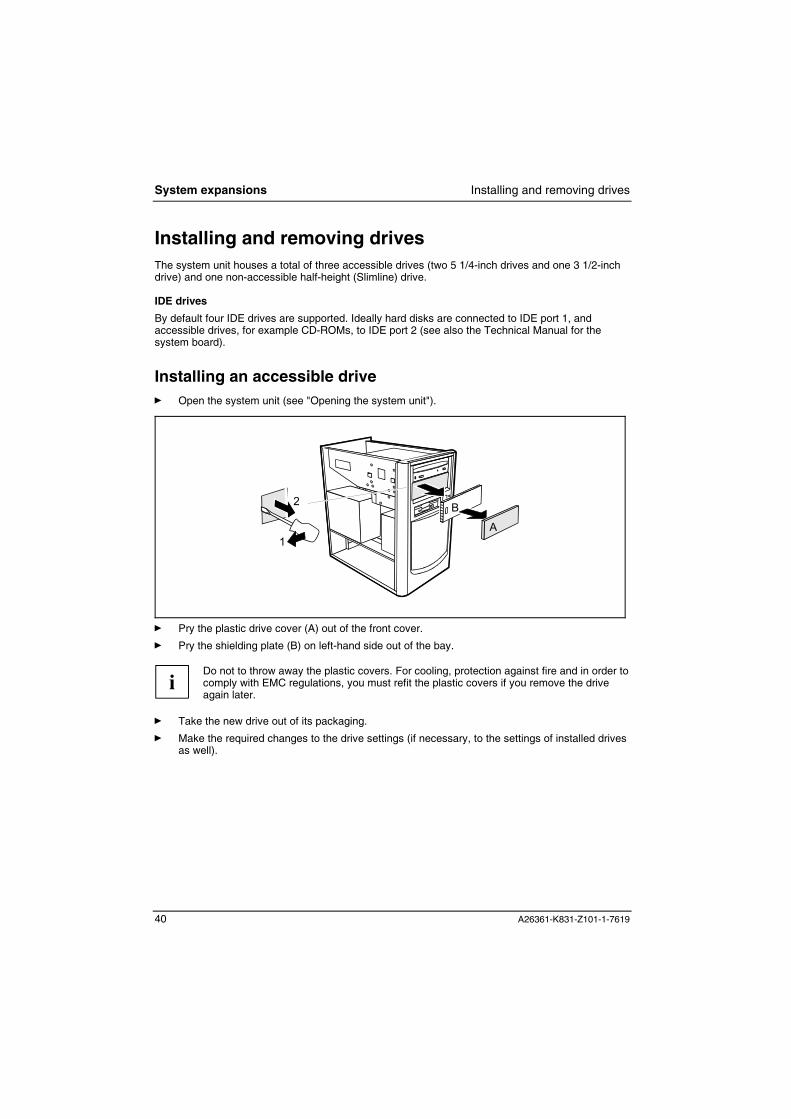
Installing an accessible driveÊ Open the system unit (see "Opening the system unit").
A
B
1
2
Ê Pry the plastic drive cover (A) out of the front cover.
Ê Pry the shielding plate (B) on left-hand side out of the bay.
i
Do not to throw away the plastic covers. For cooling, protection against fire and in order tocomply with EMC regulations, you must refit the plastic covers if you remove the driveagain later.
Ê Take the new drive out of its packaging.
Ê Make the required changes to the drive settings (if necessary, to the settings of installed drivesas well).
Installing and removing drives System expansions
A26361-K831-Z101-1-7619 41
3
1
2
2
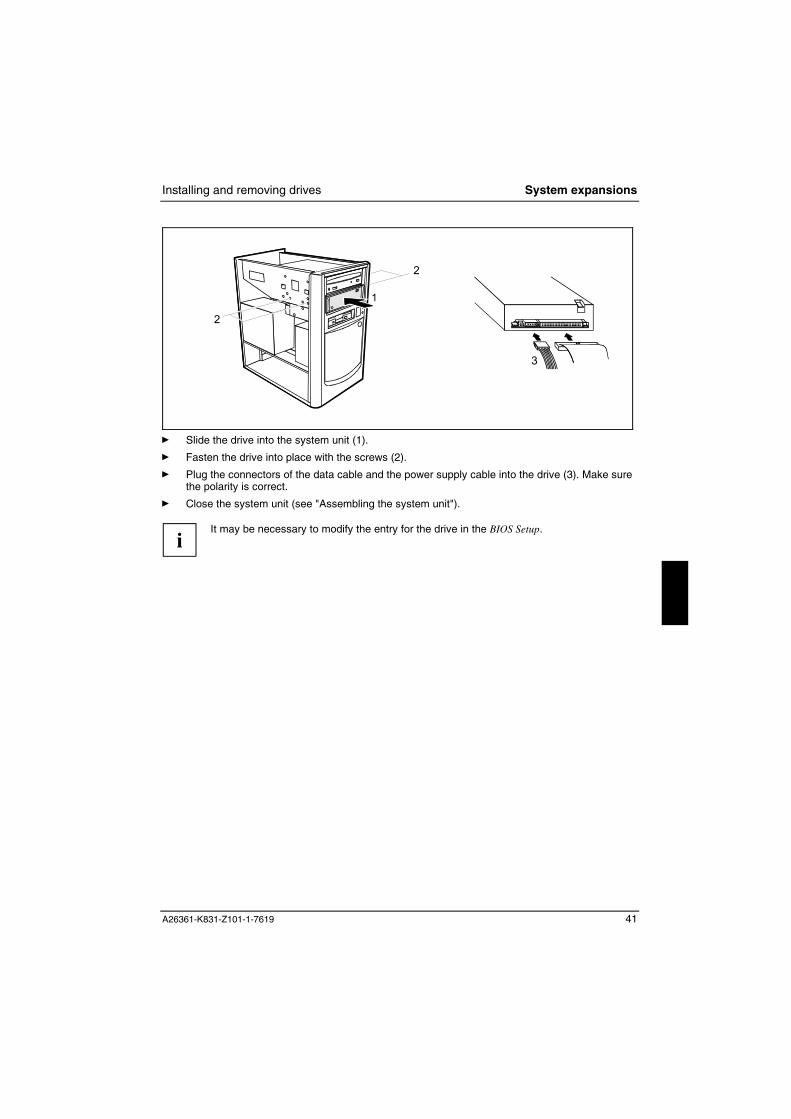
Ê Slide the drive into the system unit (1).
Ê Fasten the drive into place with the screws (2).
Ê Plug the connectors of the data cable and the power supply cable into the drive (3). Make surethe polarity is correct.
Ê Close the system unit (see "Assembling the system unit").
i
It may be necessary to modify the entry for the drive in the BIOS Setup.

System expansions Installing and removing drives
42 A26361-K831-Z101-1-7619
Removing an accessible driveÊ Open the system unit (see "Opening the system unit").
1
3
2
2
Ê Pull the data and the power supply connectors from the desired drive (1).
Ê Remove the screws (2) and take the drive out of the system unit (3).
! For cooling, protection against fire and in order to comply with EMC regulations, you mustrefit the plastic cover.
Ê Press the plastic drive cover into the front
panel until it snaps in place.
Ê Close the system unit (see "Assemblingthe system unit").
i
It may be necessary to modify the entry for the drive in the BIOS Setup.

Installing and removing drives System expansions
A26361-K831-Z101-1-7619 43
Changing the floppy disk driveÊ Open the system unit (see "Opening the system unit").
1
Ê Remove the screws (1) on the right side of the floppy disk drive.
2
13
Ê Remove the screws (1) on the left side of the floppy disk drive and pull out the drive by a fewcentimeters.
Ê Unplug the data and the power supply connectors from the floppy disk drive (2).
Ê Slide the drive carrier out of the system unit in the direction of the arrow.

System expansions Installing and removing drives
44 A26361-K831-Z101-1-7619
321
Ê Take the new floppy disk drive out of its packaging and slide it into the system unit (1).
Ê Plug the connectors of the data cable and the power supply cable into the floppy disk drive (2).Make sure the polarity is correct.
Ê Fasten the drive on the left and the right side with two screws each (3).
Ê Close the system unit (see "Assembling the system unit").
i
It may be necessary to modify the entry for the drive in the BIOS Setup.

Installing and removing drives System expansions
A26361-K831-Z101-1-7619 45
Replacing a hard disk driveÊ Open the system unit (see "Opening the system unit").
Removing the hard disk carrier
3
1
24
Ê Remove the screw (1) and push the hard disk carrier in the direction of the arrow (2) out of itssecuring lugs.
Ê Lift the hard disk carrier out of the system unit in the direction of the arrow (3).
Ê Disconnect the cables from the hard disk drive (4).

System expansions Installing and removing drives
46 A26361-K831-Z101-1-7619
Replacing a hard disk drive
1
1
Ê Remove the screws of the hard disk drive you want to replace.
Ê Take the new hard disk drive out of its packaging.
Ê Make the required settings (e.g. master/slave, stand alone) on the drives.
Ê Replace the hard disk drive.
Ê Fasten the hard disk drive with the screws.
Installing the hard disk carrier
31 2
4
Ê Connect the cables to the hard disk drive (1).
Ê Insert the hard disk carrier in the guide rail provided for this purpose on the casing (2, 3).
Ê Fasten the hard disk carrier with the screw (4).

Extensions to the system board System expansions
A26361-K831-Z101-1-7619 47
Ê Close the system unit (see "Assembling the system unit").
i
It may be necessary to modify the entry for the drive in the BIOS Setup.
Extensions to the system board Details of how and if you can upgrade the main memory or the processor of your server areprovided in the Technical Manual for the system board. Below the necessary steps are described toenable you to work on the system board.
Ê Open the system unit (see "Opening the system unit").
Upgrading main memoryÊ Upgrade the memory as described in the system board Technical Manual.
Ê Close the system unit (see "Assembling the system unit").
Replacing lithium battery
! Incorrect replacement of the lithium battery may lead to a risk of explosion.
The lithium battery may be replaced only with an identical battery or with a typerecommended by the manufacturer.
Do not throw lithium batteries into the household waste. They must be disposed of inaccordance with local regulations concerning special waste.
Ensure that you insert the battery the right way round. The plus pole must be on the top!
12 3+
++
+
Ê Lift the contact (1) a few millimetres and remove the lithium battery from its socket (2).
Ê Insert a new lithium battery of the same type into the socket (3).

System expansions Extensions to the system board
48 A26361-K831-Z101-1-7619
Replacing processor To replace the processor you must remove the system board bracket.
1
2
3
1
Ê Open the system unit (see "Opening thesystem unit").
Ê Remove all boards (see "Removing aboard").
Ê Unscrew the screw on the system boardrack (1), push the system board racksomewhat in the direction of the arrow (2)and then tilt it out upward (3).
Replace the processor (see the Technical Manual of the system board).
3
2
1
3
Ê Fold the system board rack into the casingagain (1) and push it back into its originalposition (2).
Ê Fasten the screw (3).
Ê Reinstall all boards(see "Installing a board ").
Ê Close the system unit (see "Assemblingthe system unit").

A26361-K831-Z101-1-7619 49
Technical data Electrical data
Regulations complied with: EN 60950 / VDE 0805, UL 1950CSA 22.2 No.950 Protection class: I
Rated voltage range: (selectable) 100 V - 127 V / 200 V - 240 V
Frequency: 50 Hz - 60 Hz
Power supply 110 W Power supply 200 W
Max. rated current� System unit with monitor socket:
� Monitor socket (output)
100 V -127 V / 5,5 A200 V - 240 V / 3,0 A
100 V -127 V / 3 A200 V - 240 V / 1.5 A
7,0 A3,5 A
3,0 A1,5 A
Maximum power draw in operation (peak):Minimum power draw in operation:Power draw in energy saving mode (ACPI-S3mode):Power draw in 'ready-to-operate' mode(ACPI-S3 mode):
136 W *)48 W *)
2,5 W *)
2,9 W *)Noise emission:� Sound pressure LpAm (Idle mode):� Sound power level LWAd (Operation
mode):� Sound power level LWAd (Idle mode):
28 dB *)
45 dB *)42 dB *)
*) These values only apply for a PRIMERGY econel 20 with the configuration below. Installingadditional components can cause the specified values for power draw and sound emission tobe exceeded.
Processor (256 KB cache):Main memory:Floppy disk drive:Hard disk drive:CD-ROM drive:Graphics:Audio:LAN:
Pentium 4 Prozessor 1,7 GHz128 Mbyte DDR1,44 Mbyte40 Gbyte, 7200 rpm48fachGM3000-16, NvidiaAD1885 AC'97, onboardIntel 8256ZET Ethernet Controller
Dimensions
Width/depth/height: 196 mm/350 mm/360 mm Weight
with the basic configuration ca. 8 kg (78,5 N) in basic configuration

Technical data
50 A26361-K831-Z101-1-7619
Environmental conditions
Environment class 3K2Environment class 2K2
DIN IEC 721 part 3-3DIN IEC 721 part 3-2
Temperature:� Operating (3K2)� Transport (2K2))
15 °C .... 35 °C-25 °C .... 60 °C
Condensation in operating must be avoided.
Clearance required to ensure adequate ventilation:
� left� front� rear
min. 200 mmmin. 200 mmmin. 200 mm

A26361-K831-Z101-1-7619 51
IndexAAccessible drive
installing 40removing 42
Alphanumeric keypad 22Alt Gr key 23Anti-theft protection 25Audio input 16Audio output 16
BBattery 47, 48
disposal 4BIOS Setup 24
security functions 26settings 24system settings 24
Blank monitor 30Board 35
installing 38removing 39
CCable
connecting 15disconnecting 15
Calculator keypad 22Casing
closing 37opening 36
CD-ROM driveindicator 21installing 40manual 33removing 42
CE marking 4Chain 25Class B Compliance Statement 5Cleaning 6Clearance 50Configuration, BIOS Setup 24Connecting
keyboard 8mouse 9parallel port 17serial port 17standard keyboard 8USB keyboard 8
Contents of delivery 7
Courier 1Cursor control keys 22
DData
technical 49Data protection 25Date
not correct 32Device drivers 17Devices
connecting 15, 17ports 16
Dimensions 49Diskette 24Disposal 4Drive
accessibleinstalling 40removing 42
hard diskinstalling 46
EElectrical data 49Electromagnetic compatibility 4Energy saving 3Enter key 22Ergonomic, video workstation 8Error
date 32floppy disk 31mouse 31screen 30system unit 29time 32
Error message 32ESD 35Euro key 23Expansion 35External devices
connecting 15, 17ports 16
FFCC statement 5First time switching on 12Flashing power-on indicator 21

Index
52 A26361-K831-Z101-1-7619
Floppy diskcannot read 31cannot write 31write-protection 24
Floppy disk drivechanging 43indicator 21removing 42
Function keys 22
GGame port 16Guarantee coupon booklet 7
HHard disk contents, restoring 32Hard disk drive
installing 46replacing 45
Hard disk indicator 21Headphones 16
IIDE drives 40Important notes 3Indicator
power-on indicatorgreen 21orange 21
system unit 21Installing
software 12, 14Insufficient memory 32Interfaces 16Italics 1
KKensington Lock 25Key
Control key 23Ctrl key 23
Key combination 22Keyboard 22
connecting 8Keyboard port 8, 16Keys 22
LLAN port 16Line in 16Line out 16Lithium battery 47
replacing 47, 48
MMain memory 47Manuals, further 33Memory, upgrading 47Menu key 23Microphone jack 16Monitor
cleaning 6remains blank 30switching on 12transporting 6
Monitor port 8, 16Mouse
connecting 9error 31
Mouse pointer 31Mouse port 8, 16
NNew installation, software 29New software, installing 29No picture 30Noise level 49Not enough memory 32Notational conventions 1Note
boards 35CE certificate 4disposal 4energy saving 3important 3manufacturer 3safety 3
Num Lock key 23Numeric keypad 22
OOperating, Server 19Other manuals 33Overview, Server 1
PPacking material 7Parallel port 16, 17
connecting devices 17settings 17
Ports, external devices 16Power management 33Power switch 22, 32Power-on indicator 21
dark 29Preparing for use 7Printer 16Processor 47

Index
A26361-K831-Z101-1-7619 53
Property protection 25PS/2 mouse port 8, 9, 16PS/2 mouse, connecting 9
RRated voltage
Devices with main power switch 10Devices without main power switch 10
Recycling 4Retransportation 6Return key 22
SSafety 3SCSI port 16Security functions
BIOS Setup 26MS-Windows 25SmartCard 26
Security measures 25Serial port 16, 17
connecting devices 17settings 17
Serverassembling 37cabling 15cannot be switched on 29cleaning 6connecting devices 15indicators 21opening 36ports 16ready-to-operate 20setting up 8switching off 20
devices with main powerswitch 20
devices without main powerswitch 20
switching on 12, 19devices with main power
switch 19devices without main power
switch 19switching on for the first time 12transporting 6
Setup, see BIOS SetupShift key 23SmartCard reader
operating 27
Soft power off 20Software
installing 12, 14new installation 29
Standard keyboard, connecting 8Start key 23Streamer
installing 40removing 42
Summer time 32Surface 49Symbols, explanation of 1System board carrier
installing 48removing 48
System board, extensions 47System expansion 35System settings, BIOS Setup 24System unit
trouble 29System unit, see Server
TTechnical data 49Time
daylight savings 32not correct 32
Tips 29Transport 6Trouble
floppy disk 31mouse 31screen 30
Troubleshooting 29
UUnpacking 7USB keyboard, connecting 8USB mouse, connecting 9USB port 8, 9USB, Universal Serial Bus 8, 16
VVentilation area 50Video workstation 8
WWeight 49Write protection, floppy disk 24

Information on this document On April 1, 2009, Fujitsu became the sole owner of Fujitsu Siemens Compu-ters. This new subsidiary of Fujitsu has been renamed Fujitsu Technology So-lutions.
This document from the document archive refers to a product version which was released a considerable time ago or which is no longer marketed.
Please note that all company references and copyrights in this document have been legally transferred to Fujitsu Technology Solutions.
Contact and support addresses will now be offered by Fujitsu Technology So-lutions and have the format …@ts.fujitsu.com.
The Internet pages of Fujitsu Technology Solutions are available at http://ts.fujitsu.com/... and the user documentation at http://manuals.ts.fujitsu.com.
Copyright Fujitsu Technology Solutions, 2009
Hinweise zum vorliegenden Dokument Zum 1. April 2009 ist Fujitsu Siemens Computers in den alleinigen Besitz von Fujitsu übergegangen. Diese neue Tochtergesellschaft von Fujitsu trägt seit-dem den Namen Fujitsu Technology Solutions.
Das vorliegende Dokument aus dem Dokumentenarchiv bezieht sich auf eine bereits vor längerer Zeit freigegebene oder nicht mehr im Vertrieb befindliche Produktversion.
Bitte beachten Sie, dass alle Firmenbezüge und Copyrights im vorliegenden Dokument rechtlich auf Fujitsu Technology Solutions übergegangen sind.
Kontakt- und Supportadressen werden nun von Fujitsu Technology Solutions angeboten und haben die Form …@ts.fujitsu.com.
Die Internetseiten von Fujitsu Technology Solutions finden Sie unter http://de.ts.fujitsu.com/..., und unter http://manuals.ts.fujitsu.com finden Sie die Benutzerdokumentation.
Copyright Fujitsu Technology Solutions, 2009


