Građevinar 2/2021 141 Primljen / Received: Ispravljen / Corrected: Prihvaćen / Accepted: Dostupno online / Available online: Authors: GRAĐEVINAR 73 (2021) 2, 141-151 Assoc.Prof. Davor Skejić, PhD. CE University of Zagreb Faculty of Civil Engineering [email protected]Corresponding author Domagoj Orehovec, MCE Under Hill Studio j.d.o.o. [email protected]Assist.Prof. Ivan Ćurković, PhD. CE University of Zagreb Faculty of Civil Engineering [email protected]DOI: https://doi.org/10.14256/JCE.2627.2019 24.1.2019. 4.8.2020. 20.9.2020. 10.3.2021. Prefabricated aluminium halls Professional paper Davor Skejić, Domagoj Orehovec, Ivan Ćurković Prefabricated aluminium halls Prefabricated aluminium halls are usually temporary structures with multiple uses. Their biggest advantage is low weight resulting in lower transport costs and allowing for quick assembly. Today, there is a growing demand for aluminium halls to become permanent structures, and therefore, in meeting the requirements of EN 199x norm series, it is necessary to optimize the calculation aspect of conventional structural systems with reinforced bolted joints. An overview of the most common structural systems, typical aluminium profiles and joints with steel reinforcements, as well as a common approach for design and assembly, is presented in the paper. Key words: aluminium, prefabricated halls, temporary/permanent buildings, steel reinforced joints Stručni rad Davor Skejić, Domagoj Orehovec, Ivan Ćurković Montažne aluminijske hale Aluminijske montažne hale su u pravilu privremene konstrukcije s višekratnom namjenom. Najveća prednost im je mala težina, što rezultira nižim troškovima transporta i brzom montažom. Danas se sve češće nameće zahtjev da aluminijske hale budu trajne građevine pa je, u smislu zadovoljavanja zahtjeva iz niza normi EN 199x, nužno optimizirati aspekt proračuna uobičajenih konstrukcijskih sustava s ojačanim vijčanim priključcima. U radu je dan pregled najčešćih konstrukcijskih sustava, tipičnih aluminijskih profila i priključaka s čeličnim ojačanjima, te uvriježenog pristupa kod proračuna i montaže. Ključne riječi: aluminij, montažne hale, privremene / trajne građevine, priključci s čeličnim ojačanjem Fachbericht Davor Skejić, Domagoj Orehovec, Ivan Ćurković Vorgefertigte Aluminiumhallen Vorgefertigte Aluminiumhallen sind in der Regel temporäre Konstruktionen, die für mehrere Zwecke ausgelegt sind. Ihr größter Vorteil ist das geringe Gewicht, das zu geringeren Transportkosten und einer schnellen Montage führt. Heutzutage besteht eine zunehmende Nachfrage nach dauerhaften Strukturen für Aluminiumhallen. Um die Anforderungen aus der Reihe von Normen EN 199x zu erfüllen, ist es daher erforderlich, den Budgetaspekt herkömmlicher Konstruktionssysteme mit verstärkten Schraubverbindungen zu optimieren. Die Arbeit gibt einen Überblick über die gängigsten Konstruktionssysteme, typische Aluminiumprofile und Verbindungen mit Stahlverstärkungen sowie den Standardansatz für Berechnung und Montage. Schlüsselwörter: Aluminium, vorgefertigte Hallen, temporäre / dauerhafte Strukturen, Verbindungen mit Stahlverstärkung
Transcript
Građevinar 2/2021
141
Primljen / Received:
Ispravljen / Corrected:
Prihvaćen / Accepted:
Dostupno online / Available online:
Authors:
GRAĐEVINAR 73 (2021) 2, 141-151
Assoc.Prof. Davor Skejić, PhD. CEUniversity of ZagrebFaculty of Civil [email protected] author
Assist.Prof. Ivan Ćurković, PhD. CEUniversity of ZagrebFaculty of Civil [email protected]
DOI: https://doi.org/10.14256/JCE.2627.2019
24.1.2019.
4.8.2020.
20.9.2020.
10.3.2021.
Prefabricated aluminium halls
Professional paper
Davor Skejić, Domagoj Orehovec, Ivan Ćurković
Prefabricated aluminium halls
Prefabricated aluminium halls are usually temporary structures with multiple uses. Their biggest advantage is low weight resulting in lower transport costs and allowing for quick assembly. Today, there is a growing demand for aluminium halls to become permanent structures, and therefore, in meeting the requirements of EN 199x norm series, it is necessary to optimize the calculation aspect of conventional structural systems with reinforced bolted joints. An overview of the most common structural systems, typical aluminium profiles and joints with steel reinforcements, as well as a common approach for design and assembly, is presented in the paper.
Aluminijske montažne hale su u pravilu privremene konstrukcije s višekratnom namjenom. Najveća prednost im je mala težina, što rezultira nižim troškovima transporta i brzom montažom. Danas se sve češće nameće zahtjev da aluminijske hale budu trajne građevine pa je, u smislu zadovoljavanja zahtjeva iz niza normi EN 199x, nužno optimizirati aspekt proračuna uobičajenih konstrukcijskih sustava s ojačanim vijčanim priključcima. U radu je dan pregled najčešćih konstrukcijskih sustava, tipičnih aluminijskih profila i priključaka s čeličnim ojačanjima, te uvriježenog pristupa kod proračuna i montaže.
Vorgefertigte Aluminiumhallen sind in der Regel temporäre Konstruktionen, die für mehrere Zwecke ausgelegt sind. Ihr größter Vorteil ist das geringe Gewicht, das zu geringeren Transportkosten und einer schnellen Montage führt. Heutzutage besteht eine zunehmende Nachfrage nach dauerhaften Strukturen für Aluminiumhallen. Um die Anforderungen aus der Reihe von Normen EN 199x zu erfüllen, ist es daher erforderlich, den Budgetaspekt herkömmlicher Konstruktionssysteme mit verstärkten Schraubverbindungen zu optimieren. Die Arbeit gibt einen Überblick über die gängigsten Konstruktionssysteme, typische Aluminiumprofile und Verbindungen mit Stahlverstärkungen sowie den Standardansatz für Berechnung und Montage.
Schlüsselwörter:
Aluminium, vorgefertigte Hallen, temporäre / dauerhafte Strukturen, Verbindungen mit Stahlverstärkung
Građevinar 2/2021
142 GRAĐEVINAR 73 (2021) 2, 141-151
Davor Skejić, Domagoj Orehovec, Ivan Ćurković
1. Introduction
Aluminium is a material that is used in construction due to its obvious advantages such as low weight, corrosion resistance, and cross-section functionality [1]. As such, it is highly suitable for application in structures that are built in aggressive environments. Also, due to its low specific weight-to-density ratio, aluminium is applied in places where transport is difficult, or at inaccessible places requiring unconventional means of transport. In addition to cheaper transport, aluminium structures are easier to assemble and do not require heavy machinery or cranes for their erection. Finally, the cross-sectional functionality, resulting from a conventional profile production process using extrusion, ensures optimization of the aluminium alloy consumption regarding its purpose, i.e. regarding the purpose of the aluminium profile itself [2].The application of prefabricated aluminium halls varies to a great extent, as shown in Figure 1. These halls can be used as temporary structures or even as permanent self-standing structures. Since they are usually used as prefabricated halls, most often for some short-term events (weddings, concerts, temporary warehouses, etc.), the structure itself is assembled and dismantled numerous times, and so it can be stated that the application of aluminium elements is an optimal solution. It is a known fact that aluminium is three times lighter than steel, which increases the speed of transport, assembly and dismantling, and the entire process can be carried out by a smaller number of workers, Figure 2. Lower maintenance requirements are also associated with this type of structure because aluminium is, unlike steel, not susceptible to corrosion. All these facts result in a lower overall price of aluminium halls.
Figure 1. Aluminium hall as a warehouse space or space for wedding ceremonies
Since welding of aluminium alloys causes significant reduction in resistance [3], aluminium elements are mainly joined using bolts. Steel reinforcements are applied to the outer or inner side of the aluminium elements, usually at joints. Furthermore, the modulus of elasticity of aluminium is three times smaller than that of steel, and so deflection of aluminium structures is higher compared to steel structures. Therefore, in order to satisfy
serviceability limit state requirements, aluminium structures need to use somewhat larger profile dimensions than it would be required for equivalent steel structures. Moreover, the idea of aluminium profile reinforcement using steel elements at the points of structure’s joints can also positively affect reduction of aluminium profile dimensions [4].
Figure 2. Assembly of aluminium hall
As to the use of such temporary buildings, it should be mentioned that they are applied in places where fast performance is needed, such as fairs, where they are assembled and dismantled as needed. In addition, they can be used to cover pools and other structures in humid environments.A detailed description of the most commonly used aluminium structures, prefabricated halls, is given below in order to popularize the application of aluminium alloys in Croatia. Commonly used structural systems are presented, and a review of cross-sectional shapes used in these systems is given. To optimize the structure, the joints used in these structures are constructed in combination with steel elements. It is important to note that such joints are not covered by the design code, and that their design is based more on engineering intuition than on actual knowledge of their behaviour, which also requires further investigation. Moreover, such temporary structures often remain in use for a much longer period of time than initially planned. Thus, it is necessary to consider their reliable design from this aspect as well. In the final part of the paper, the assembly procedure of prefabricated aluminium halls is briefly described to further highlight advantages of such structural systems.
2. Main structural systems
2.1. General
Available dimensions of prefabricated aluminium halls depend on their manufacturer as well as on the type of cross-sections offered by the supplier. Usually, prefabricated warehouses and prefabricated fair halls have frame spans from 5 to 30 meters if they are constructed without inner columns. The eave height ranges from 3.5 to 4.5 meters, while the spacing of the main frames is about 5 meters. The height of the prefabricated hall at ridge is up to 7.5 meters. The cover is usually made of lightweight
Građevinar 2/2021
143GRAĐEVINAR 73 (2021) 2, 141-151
Prefabricated aluminium halls
and non-flammable PVC foil and less often of metal sheets. Corrugated steel sheets or various panel elements can be used as a facade. The PVC foil is connected using specially designed systems - profiles with beadings, while metal sheets for the roof or façade are connected using screws and pop rivets, which again ensures the basic advantage of such halls, i.e. quick assembly.
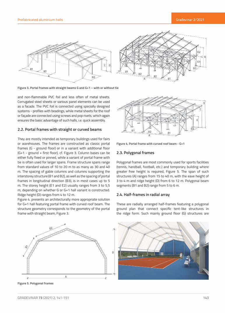
2.2. Portal frames with straight or curved beams
They are mostly intended as temporary buildings used for fairs or warehouses. The frames are constructed as classic portal frames (G - ground floor) or in a variant with additional floor (G+1 - ground + first floor), cf. Figure 3. Column bases can be either fully fixed or pinned, while a variant of portal frame with tie is often used for larger spans. Frame structure spans range from standard values of 10 to 20 m to as many as 30 and 40 m. The spacing of gable columns and columns supporting the interstorey structure (B1 and B2), as well as the spacing of portal frames in longitudinal direction (B3), is in most cases up to 5 m. The storey height (E1 and E2) usually ranges from 3 to 5,5 m, depending on whether G or G+1 hall variant is constructed. Ridge height (D) ranges from 4 to 12 m.Figure 4. presents an architecturally more appropriate solution for G+1 hall featuring portal frame with curved roof beam. The structure geometry corresponds to the geometry of the portal frame with straight beam, Figure 3.
Figure 4. Portal frame with curved roof beam - G+1
2.3. Polygonal frames
Polygonal frames are most commonly used for sports facilities (tennis, handball, football, etc.) and temporary building where greater free height is required, Figure 5. The span of such structures (A) ranges from 15 to 40 m, with the eave height of 3 to 4 m and ridge height (D) from 6 to 12 m. Polygonal beam segments (B1 and B2) range from 5 to 6 m.
2.4. Half-frames in radial array
These are radially arranged half-frames featuring a polygonal ground plan that connect specific tent-like structures in the ridge form. Such mainly ground floor (G) structures are
Figure 3. Portal frames with straight beams G and G+1 – with or without tie
Figure 5. Polygonal frames
Građevinar 2/2021
144 GRAĐEVINAR 73 (2021) 2, 141-151
Davor Skejić, Domagoj Orehovec, Ivan Ćurković
commonly referred to as pavilions and are used for fairs and similar manifestations, Figure 6. Their span (A) ranges from 10 to 30 m, circumferential frame spacing (B) is usually between 5 and 6 m, the eave height (C) is between 3 and 4 m, while the ridge height (D) is within the range of 5 to 9 m.
3. Selection of aluminium profile cross-section
Aluminium profile cross-sections are favourably shaped, i.e. due to production process of profiles by extrusion, arbitrary cross-sections – appropriate for particular needs - can be produced, which is one of the main advantages of aluminium alloys. This optimizes the shape functionality of aluminium profiles, an in turn reduces unnecessary waste of material. Some manufacturers offer various cross-section types that are prefabricated for specific purposes. For example, in prefabricated aluminium structures, special types of cross-sections are used for tent structures (using PVC foil lining). In this case, profiles with beadings designed to fit PVC tent covers are used. Typical aluminium rectangular tubular shapes with one-sided or two-sided beadings are shown in Figure 7.
Figure 7. Typical cross-sections of aluminium profiles with beadings [6]
The profile type selection primarily depends on the purpose of the building. Most commonly, the profiles with two beadings are used in buildings where there is no need for thermal insulation,
as shown in Figure 7.a). Profiles with 4 beadings, figures 7.b) and 7.c), allow for two layers of building cover where the air-filled space between the two layers serves as thermal insulator.Furthermore, the selection of cross-section dimensions is solely related to the bearing capacity of the building itself. Some manufacturers provide guidance on the selection of profile dimensions as related to the span of the structure. For example, profiles of 150 mm in height and 120 mm in width (150 x 120) are used for single storey halls up to 15 m in span, profiles measuring 250 x 120 mm are used for halls up to 30 m in span, while 300 x 120 profiles are used for 50 m spans [7].As far as the material itself is concerned, wrought heat-treatable aluminium alloys of the 6xxx series, belonging to the durability class B, are used [2]. The most commonly selected alloys are the ones which, by their mechanical properties, correspond to steel grade S 235, e.g. EN-AW 6005A. These alloys are suitable for the extrusion of general-purpose profiles, as well as for structural products where medium strength material properties are required. Furthermore, these alloys exhibit a high level of corrosion resistance as well as a good thermal processing capability.
4. Joints in prefabricated halls
4.1 General
Joints in prefabricated aluminium halls are made using steel adapters (inserts and/or cover plates), which are added either to the beam-to-beam joints at the roof ridge or to the beam-to-column joints. If needed, steel inserts can also be added to the column base, but such solution slows down the assembly process. Typical joints of prefabricated aluminium halls are: column base, beam-to-column joint, beam-to-beam joint and secondary beam (purlin)-to-beam joint, Figure 8.Prefabricated aluminium-hall joints can be formed using bolts made of various materials, which will in most cases depend on environmental conditions in which the hall is situated, as well as on the assumed period of its use. Hot-dipped galvanized steel bolts are most often used. However, stainless steel bolts are utilized in extremely humid (marine) environments, while aluminium bolts are very rarely used. The design of joints in which metals of different potentials are in contact can lead to the formation of galvanic cells and, ultimately, to the occurrence of contact
Figure 6. Half-frames in radial array [5]
Građevinar 2/2021
145GRAĐEVINAR 73 (2021) 2, 141-151
Prefabricated aluminium halls
corrosion. Since prefabricated aluminium halls are intended for temporary use only, the problem of contact corrosion is rarely encountered. Moreover, the halls that remained in use longer than initially expected did not show any problems with contact corrosion when additional hot-dip galvanized steel elements were used. This observation is due to either too little electrolyte (relative humidity of less than 70%), or small differences in electrical potential of individual elements (tolerance of 0.25 V in electric potential is allowed if used in storage areas without control of relative humidity and room temperature), or a well-matched ratio of the amount of elements, one being an anode and the other a cathode (an element that acts as an anode must always be larger than the one that acts as a cathode).
4.2. Column base
Various types of connections between the column base and foundation can be used, which depends on the amount of the clamping force that can be transmitted between the two. Figure 9. shows possible solutions for the column base, depending on how the hall is modelled (whether there is transfer of moment to the foundation or not), assembly speed (time), and purpose of the building. The z-z axis, Figure 9, represents the direction in which
the frame is spanning, i.e. the transverse direction of the hall, while the y-y axis represents its longitudinal direction.The application of a steel insert shown in Figure 9.a) in the column base joints provides transfer of clamping force in both directions (y-y and z-z axes) but the downside of such joint configuration lies in its slower assembly. Faster assembly is achieved using hinged joints that are (fully) clamped around one axis only (y-y axis), Figs. 9.b) and 9.c). In that case, joint detail with a classical steel pin, Figure 9.b), represents a more economical choice compared to the joint detail shown in Figure 9.c).As to the connection between the column base and ground, two options can be distinguished: anchoring, Figure 10., and ballasting, Figure 11. Selection
of an appropriate connection option depends primarily on the foundation soil itself, i.e. its bearing capacity, possibility of pouring conventional foundations, as well as on the purpose of the building itself, or the time of its usage. Figure 10 shows ground fixing solutions using anchors. The solution with anchor bolts used for heavy loading is shown in the first option, Figure 10.a). The second option, Figure 10.b), involves the use of wedges that are driven directly into the ground (soil, gravel, asphalt…). Such a solution is most often used in the case of temporary buildings with lower load intensity, and for buildings to be used for a shorter period of time. It is important that the ground beneath the column base is firm enough to avoid major structural deformations, and to ensure enough friction between the ground and the wedge to prevent its pull-out.In case when it is not possible to provide conventional foundations or make modifications in the existing ground (base material), the connection between the structure and the ground is ensured through ballasting. When using such solution, the building is surrounded with weights to stay firm. The weights in the form of concrete blocks are commonly used, Figure 11. Ballasting solution is almost always used in the case of short-term use of buildings.
Figure 8. Characteristic joints of prefabricated aluminium hall
Figure 9. Column base variants
Građevinar 2/2021
146 GRAĐEVINAR 73 (2021) 2, 141-151
Davor Skejić, Domagoj Orehovec, Ivan Ćurković
Figure 11. Securing the structure stability through ballasting (heavy anchor blocks)
4.3. Joints of frame elements
Frame elements of aluminium halls are commonly joined using steel reinforcements. Two of the most common joining solutions include reinforcing with steel cover plates and steel inserts. Steel inserts are welded in the shop, while aluminium profiles are bolted onto them at the construction site. Apart from steel inserts, these joints can be formed using steel cover plates that are connected to aluminium profiles on both sides either using bolts and/or pins. Due to simplicity of connection between elements, the latter solution ensures faster assembly but, in many cases, this type of joint cannot provide the required resistance and stiffness for permanent usage of such buildings, which they often have.
4.3.1. Joints with steel cover plates
In this case, aluminium is reinforced with steel plates placed on both outer sides of aluminium profiles, Figure 12. These joints are assembled at the construction site, most often using bolts or, much less often, using pins. They are most commonly used in temporary
structures. The advantage of these joints is a clear force transmission path through connectors, which allows simple calculation, as well as fast assembly and dismantling.
4.3.2. Joints with steel inserts
Joints with steel inserts are made by inserting the steel tube profile inside
the aluminium tube profile. In this way, steel insert reinforces aluminium elements, allowing force transfer from one element to another, e.g. from beam to column or from beam to beam (at the roof ridge), Figure 13. These joints are assembled at the construction site using bolts.The issue with these prefabricated-hall joints lies in complex force transfer, where the transfer of moment from the aluminium profile to the steel insert is achieved partly through their contact and partly through bolt connection. The load bearing mechanism in such joint can be approximated with the force couple acting on the steel insert, thus loading the element and/or the bolt connection.
Figure 10. Variants of connection between column and ground
Figure 12. Beam-to-column joint with steel cover plates [8]
Figure 13. Beam-to-column joint using steel insert
Figure 14. Beam-to-column joint, solution with diagonal strut and tie
Građevinar 2/2021
147GRAĐEVINAR 73 (2021) 2, 141-151
Prefabricated aluminium halls
Additional tie and/or diagonal strut is necessary for larger spans of prefabricated halls or for higher gravity loading (snow), Figure 14. Such solutions alter the load bearing mechanism within the structure and within the beam-to-column joint, and make it even more difficult to calculate resistance of the joint itself.
4.4. Purlin-to-beam joints
Secondary beams (purlins) can be made either from aluminium or steel material which depends on: purpose of the building, temporary or permanent use, loads acting on the building, spans of the purlins, type of connection to the frame beam, etc. A simply supported beam structural system is most commonly used. Steel profiles with bolted front plate connection are usually used for buildings of more permanent nature (e.g. warehouses), Figure 15.Aluminium profiles are used for buildings destined for short-term use (tents, party halls…). For these buildings, the emphasis is on simplicity and speed of assembly, which is why clamp connections are used, Figure 16.
5. Design of prefabricated aluminium halls
When designing a prefabricated aluminium hall, it is first of all necessary to consider whether it will be used as a temporary or a permanent building. The situation is in most cases clear, because the original idea of aluminium prefabricated halls stems from the requirement for structures that will serve for various time-limited events, which is why their usage is mostly limited to a period of about ten days, or even to no more than a few days. However, often the predicted short-term usage of the building is extended, by the owner’s decision, to the permanent usage. Therefore, it would be desirable that structures that are to be used for a longer period of
time, or even structures that are suspected to remain permanently in use, are designed as permanent in accordance with the series of structural Eurocodes (HRN) EN 199x which are referenced by the currently valid technical regulation (in Croatia - [9]). Regardless of whether temporary or permanent prefabricated aluminium halls are in question, the design of aluminium elements is carried out in accordance with (HRN) EN 1999-1-1 [10].If these temporary aluminium halls are covered with PVC foil (which is most often the case) design work can be carried out in accordance with requirements of (HRN) EN 13782 [11] which is related to temporary structures of tents. According to (HRN) EN 13782 [11], the snow and wind load determination for temporary structures varies from the methods used for permanent structures, which are carried out solely according to (HRN) EN 1991-1-3 [12] and (HRN) EN 1991-1-4 [13] for snow and wind load, respectively.Unlike permanent structures, in the case of temporary buildings, snow loads do not need to be taken into account for buildings built in areas where there is a low possibility od snow, in the case when they are used only at a certain time of the year in which snow is not expected, or in the case when activities for preventing snow retention at the roof are planned in advance [11]. The last requirement can be met by installing heating equipment, taking care that the heating begins before snowfall, that the whole building is heated in such a way that the temperature on the outside of the cover (tent) is higher than +2 °C, and that water retention and additional structural loading is prevented. In the event when the highest snow height of 8 cm is secured through its regular removal, a reduced snow load of 0.20 kN/m2 can be adopted for the entire roof surface.Determination of wind load for temporary buildings is based on (HRN) EN 1991-1-4 [13] but, in that case the location, duration and period of erection, the way the structure is used, protection
Figure 15. Steel purlin
Figure 16. Aluminium purlin
Građevinar 2/2021
148 GRAĐEVINAR 73 (2021) 2, 141-151
Davor Skejić, Domagoj Orehovec, Ivan Ćurković
possibilities, and the specific nature of the canvas that can be made of various materials (textile, PVC), must all be taken into account. For any location where the fundamental value of the basic wind velocity, vb,0, is greater than 28 m/s, the stability and resistance calculations must be carried with respect to local conditions. For the calculation of peak velocity pressures, qp(ze), (HRN) EN 1991-1-4 [13] is applied, taking into account requirements given in national annexes. The obtained values can be reduced by a factor of 0,7.For locations where fundamental value of the basic wind velocity, vb,0, is lower than or equal to 28 m/s, the wind load, according to (HRN) EN 13782 [11], can be calculated as given in Table 1. Contrary to the values given in Table 1. a reduced value of peak velocity pressure qp(ze) = 0,30 kN/m2 can be adopted in the case when the tent width and height are lower than or equal to 10 m or 5 m, respectively.
Table 1. Peak velocity pressure [11]
Peak velocity pressures for wind speed of 28 m/s adopted from (HRN) EN 13782 [11] and calculated according to (HRN) EN 1991-1-4 [13], for two extreme terrain categories, are compared in Table 2. The values obtained using (HRN) EN 13782 [11] are almost always lower than the ones calculated using (HRN) EN 1991-1-4 [13], even for the most favourable terrain category IV. According to (HRN) EN 13782 [11], a slightly higher value (0,60 instead of 0,58) is obtained for a reference height of 10 m only.The above data show that proper consideration of the building lifespan (temporary or permanent) is crucial for optimizing the design of prefabricated aluminium halls. Considering the fact that striving towards optimized construction of such buildings is very important, further development of the design process for aluminium elements and their joints, as well as understanding of their physical behaviour, is a prerequisite for the wider
application of these lightweight and very often economically justified structures.If the building is designed as a permanent structure it is necessary to include fire action in the structure calculation process. Since aluminium alloys are extremely sensitive to high temperatures that occur during fire, the reduction of their mechanical properties [14], i.e. the loss of resistance can be anticipated very early. For this reason, it is crucial to apply current (up-to-date) methods for estimating fire development taking into account properties of the cover materials specific to such structures.
6. Assembly
The advantage of prefabricated aluminium halls can best be seen at the assembly phase, especially in the case of temporary structures (short-term event halls), Figure 1., which can be assembled and again dismantled in a short period of time. The fact that aluminium as a material has low specific weight and that no welded joints are used at the construction site, significantly accelerates the assembly and dismantling of the structure. As a result, less workforce and machinery is needed, which in turn reduces construction costs.The preparatory phase of the prefabricated aluminium hall is carried out in the workshop through preparation and grouping of the elements, and their palletization, which enables easier manipulation and transport to the construction site, Figure 17.
Figure 17. Storage of prefabricated elements at construction site
Measuring and setting the column bases is the first step of the structure assembly process at the construction site.
Reference height ze
[m]
Peak velocity pressure for 28 m/s - qp(ze) [kN/m2]
HRN EN 13782 [11] HRN EN 1991-1-4 [13]. terrain category IV HRN EN 1991-1-4 [13]. terrain category 0
5 0.50 0.58 1.27
10 0.60 0.58 1.47
15 0.66 0.71 1.58
20 0.71 0.81 1.67
25 0.76 0.89 1.72
Reference height ze [m]
Peak velocity pressure qp(ze) [kN/m2]
ze ≤ 5 0.50
5 < ze ≤ 10 0.60
10 < ze ≤ 15 0.66
15 < ze ≤ 20 0.71
20 < ze ≤ 25 0.76
Table 2. Comparison of peak velocity pressures for wind velocity of 28 m/s
Građevinar 2/2021
149GRAĐEVINAR 73 (2021) 2, 141-151
Prefabricated aluminium halls
Column bases are connected to the ground using either anchor bolts or wedges. The selection of anchoring type depends on the ground type at the site, and on load intensity, Figure 10. Main load bearing frames are assembled at the ground, and are erected one by one and then interconnected using secondary structural elements (purlins), Figure 18. As a rule of thumb, the assembly always starts with the bay that has vertical braces, i.e. by formation of a spatially stable part of the structure.The use of hinged column base variants allows rotation about z-z axis, figures 9.b) and 9.c), which significantly speeds up assembly of the structure itself. Namely, after the frames are assembled at the ground, they are connected to their bases and are then erected in such a way that they rotate around the hinged column base, Figure 19. The machinery used to erect the frame structure is a mobile crane and/or a forklift, while scissor
lifts are usually used for connecting the frame to the rest of the structure. In order to ensure the stability of the structure during all assembly phases, the assembly procedure itself starts from the field in which the vertical longitudinal bracing is located. In the final phase of assembly, the rest of the secondary structure, including stabilisation elements, is installed and tightened, Figure 20. After installation of the cover (PVC foil), additional tensioning of the tensile elements (stabilization diagonals and ties) is performed.The covering and openings are installed in accordance with the intended use of the structure. The most commonly used cover is PVC foil, although the structure can be closed using sandwich panels or trapezoidal steel sheets, Figure 21. The openings and doors are selected according to the use of the structure, and can range from ordinary PVC curtains to sophisticated glazed aluminium doors.
Figure 18. Assembly of frames on the ground
Figure 19. Frame erection and connection to the rest of the structure
Figure 20. Installation of secondary elements and stabilization
Građevinar 2/2021
150 GRAĐEVINAR 73 (2021) 2, 141-151
Davor Skejić, Domagoj Orehovec, Ivan Ćurković
7. Conclusion
Prefabricated aluminium halls are polyvalent structures that can be used in a variety of ways. The biggest advantage is their low weight, resulting in lower transport costs, and in quick and economical assembly, with no need for big and heavy machinery. Simple connection and dismantling allow multiple use for various purposes at diverse locations. Furthermore, it should be noted that from the production and installation aspect, aluminium can be considered as a “green” material, i.e. material that is highly consistent with the philosophy of sustainability. High percentage of recyclability and the fact that structural aluminium alloys practically do not need to be protected against corrosion processes (and also do not need any maintenance), additionally point to the value of aluminium as a structural material.The aforementioned advantages have contributed to the growing demand for construction of permanent aluminium
halls. To this end, practicing engineers need reliable solutions and simplified proofs for fast design of aluminium halls, i.e. their elements and joints. Some of these activities, focusing on behaviour of aluminium joints, have already been carried out at the Faculty of Civil Engineering of the University of Zagreb [15-17].Recently, designers have been increasingly successful in meeting requirements of investors with regard to the application of prefabricated aluminium halls. We hope that the published material will solve many unknowns that arise when designing these extremely economical structural solutions.
Acknowledgment
The authors express their thanks to company HALTOR d.o.o. (Samobor, Croatia) for providing photo documentation of realised buildings and a set of practical advice regarding production and assembly of prefabricated aluminium halls and tents.
Figure 21. Structure covering and installation of openings
REFERENCES[1] Boko, I., Skejić, D., Torić, N.: Aluminijske konstrukcije, Sveučilište u
Splitu, Fakultet građevinarstva, arhitekture i geodezije, Udžbenik Sveučilišta u Splitu i Udžbenik Sveučilišta u Zagrebu, Split, 2017.
[2] Skejić, D., Boko, I., Torić, N.: Aluminium as a material for modern structures, GRAĐEVINAR, 67 (2015) 11, pp. 1075-1085, https://doi.org/10.14256/JCE.1395.2015
[3] Dokšanović, T., Markulak, D., Džeba, I.: Stanje područja stabilnosti i zavarivanja elemenata od aluminijskih legura, GRAĐEVINAR, 66 (2014) 2, pp. 115-125, https://doi.org/10.14256/JCE.932.2013
[4] Gligić, B., Buđevac, D, Marković, Z., Mišković, Z.: Nosači od aluminijskih legura ojačani elementima od čelika, GRAĐEVINAR, 68 (2016) 10, pp. 787-799, https://doi.org/ 10.14256/JCE.1588.2016
[5] Pavillion type C 25.00M, 12-SIDED, www.eschenbach-group.com, 13.12.2018.
[6] Ingrid L. Blecha Gmbh: Program isporuke 2018, katalog proizvođača, www.blecha.at, 13.12.2018.
[9] Ministarstvo graditeljstva i prostornoga uređenja: Tehnički propis za građevinske konstrukcije, NN 17/17, Zagreb, 2017.
[10] Hrvatski zavod za norme (HZN): HRN EN 1999-1-1, Eurokod 9: Projektiranje aluminijskih konstrukcija - Dio 1-1: Opća pravila (EN 1999-1-1:2007+A1:2009+A2:2013), drugo izdanje, Hrvatski zavod za norme, Zagreb, 2015.
[11] Hrvatski zavod za norme (HZN): HRN EN 13782, Privremene konstrukcije - Šatori – Sigurnost (EN 13782:2015), drugo izdanje, Hrvatski zavod za norme, Zagreb, 2015.
[12] Hrvatski zavod za norme (HZN): HRN EN 1991-1-3, Eurokod 1: Djelovanja na konstrukcije - Dio 1-3: Opća djelovanja - Opterećenja snijegom (EN 1991-1-3:2003+AC:2009), drugo izdanje, Hrvatski zavod za norme, Zagreb, 2012.
[13] Hrvatski zavod za norme (HZN): HRN EN 1991-1-4, Eurokod 1: Djelovanja na konstrukcije - Dio 1-4: Opća djelovanja - Djelovanja vjetra (EN 1991-1-4:2005+AC:2010+A1:2010), drugo izdanje, Hrvatski zavod za norme, Zagreb, 2012.
Građevinar 2/2021
151GRAĐEVINAR 73 (2021) 2, 141-151
Prefabricated aluminium halls
[14] Skejić, D., Ćurković, I., Jelčić Rukavina, M.: Behaviour of Aluminium Structures in Fire, 4th International Conference on APPLICATIONS OF STRUCTURAL FIRE ENGINEERING, ASFE’15, Dubrovnik, pp. 300-305, 2015.
[15] Harasti, D.: Eksperimentalna i numerička analiza aluminijskog nosača s čeličnom ispunom, diplomski rad, Sveučilište u Zagrebu, Građevinski fakultet, 2018.
[16] Josipović, M.: Ponašanje aluminijskog montažnog priključka prečka-stup, diplomski rad, Sveučilište u Zagrebu, Građevinski fakultet, 2018.
[17] Skejić, D., Mazzolani, F., Ćurković, I., Damjanović, D.: Experimental testing of prefabricated aluminium knee joints reinforced by steel, 14th International Aluminium Conference (INALCO2019): Environmental Advantages of Sustainable Aluminium Structures - Sustainability, Durability and Life Cycle, Ito International Research Center, Proceedings of 14th INALCO2019, Japan Light Metal Welding Association, Japan Aluminium Association, pp. 160-161, 2019, Tokyo, Japan.
[18] Skejić, D.; Čudina, I.; Garašić, I.; Mazzolani, F. M.: Behaviour of steel tubular knee joint in aluminium frames with tension-tie element, Applied Sciences-Basel, 1 (2021) 70, pp. 1-18.