82
PRINCIPLE OF MACHINE TOOLS

PRINCIPLE OF MACHINE TOOLS
1.1 INTRODUCTION
UNIT – I
MACHINE TOOLS
In an industry, metal components are made into different shapes and dimensions by using
various metal working processes.
Metal working processes are classified into two major groups. They are:
Non-cutting shaping or chips less or metal forming process - forging, rolling, pressing, etc.
Cutting shaping or metal cutting or chip forming process - turning, drilling, milling, etc.
1.2 MATERIAL REMOVAL PROCESSES
1.2.1 Definition of machining
Machining is an essential process of finishing by which work pieces are produced to the desired
dimensions and surface finish by gradually removing the excess material from the preformed blank in
the form of chips with the help of cutting tool(s) moved past the work surface(s).
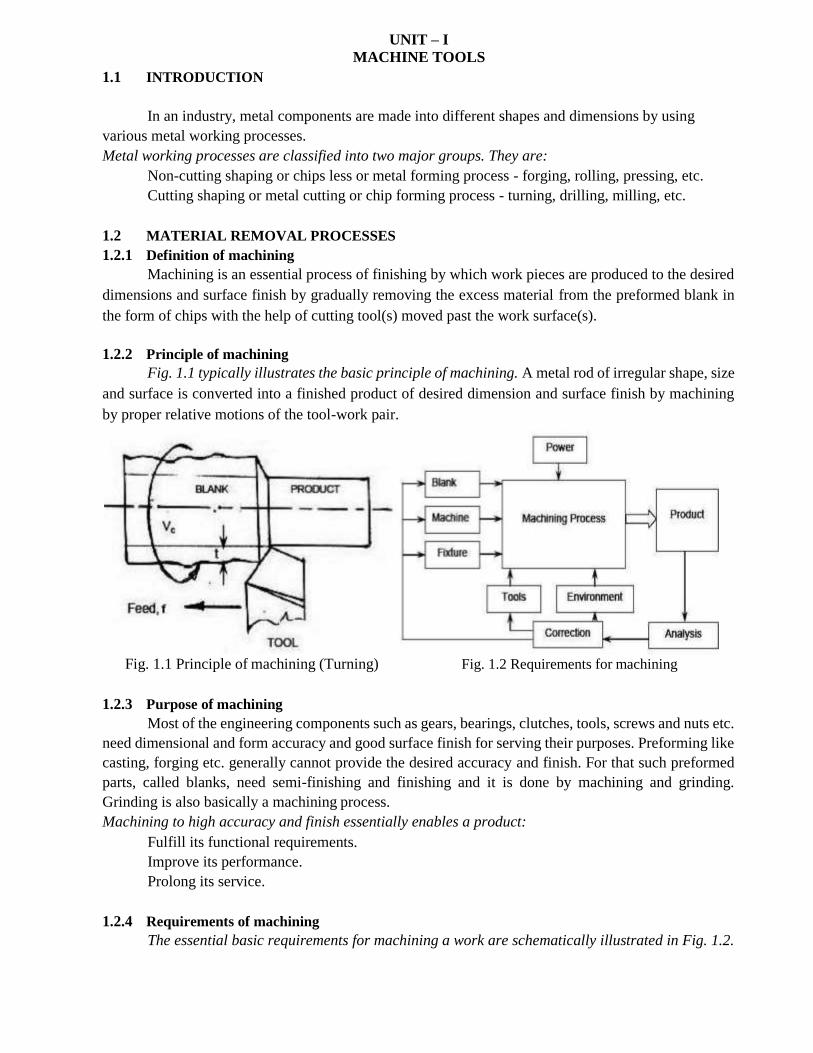
1.2.2 Principle of machining
Fig. 1.1 typically illustrates the basic principle of machining. A metal rod of irregular shape, size
and surface is converted into a finished product of desired dimension and surface finish by machining
by proper relative motions of the tool-work pair.
Fig. 1.1 Principle of machining (Turning) Fig. 1.2 Requirements for machining
1.2.3 Purpose of machining
Most of the engineering components such as gears, bearings, clutches, tools, screws and nuts etc.
need dimensional and form accuracy and good surface finish for serving their purposes. Preforming like
casting, forging etc. generally cannot provide the desired accuracy and finish. For that such preformed
parts, called blanks, need semi-finishing and finishing and it is done by machining and grinding.
Grinding is also basically a machining process.
Machining to high accuracy and finish essentially enables a product:
Fulfill its functional requirements.
Improve its performance.
Prolong its service.
1.2.4 Requirements of machining
The essential basic requirements for machining a work are schematically illustrated in Fig. 1.2.
The blank and the cutting tool are properly mounted (in fixtures) and moved in a powerful device
called machine tool enabling gradual removal of layer of material from the work surface resulting in its
desired dimensions and surface finish. Additionally some environment called cutting fluid is generally
used to ease machining by cooling and lubrication.
1.3 TYPES OF MACHINE TOOLS
1.3.1 Definition of machine tool
A machine tool is a non-portable power operated and reasonably valued device or system of
devices in which energy is expended to produce jobs of desired size, shape and surface finish by
removing excess material from the preformed blanks in the form of chips with the help of cutting tools
moved past the work surface(s).
1.3.2 Basic functions of machine tools
Machine tools basically produce geometrical surfaces like flat, cylindrical or any contour on
the preformed blanks by machining work with the help of cutting tools.
The physical functions of a machine tool in machining are:
Firmly holding the blank and the tool.
Transmit motions to the tool and the blank.
Provide power to the tool-work pair for the machining action.
Control of the machining parameters, i.e., speed, feed and depth of cut.
1.3.3 Classification of machine tools
Number of types of machine tools gradually increased till mid 20th
started decreasing based on group technology.
However, machine tools are broadly classified as follows:
According to direction of major axis:
➢ Horizontal - center lathe, horizontal boring machine etc.
➢ Vertical - vertical lathe, vertical axis milling machine etc.
➢ Inclined - special (e.g. for transfer machines).
According to purpose of use:
century and after that
➢ General purpose - e.g. center lathes, milling machines, drilling, machines etc.
➢ Single purpose - e.g. facing lathe, roll turning lathe etc.
➢ Special purpose - for mass production.
According to degree of automation:
➢ Non-automatic - e.g. center lathes, drilling machines etc.
➢ Semi-automatic - capstan lathe, turret lathe, hobbing machine etc.
➢ Automatic - e.g., single spindle automatic lathe, swiss type automatic lathe, CNC
milling machine etc.
According to size:
➢ Heavy duty - e.g., heavy duty lathes (e.g. ≥ 55 kW), boring mills, planning machine,
horizontal boring machine etc.
Medium duty - e.g., lathes - 3.7 ~ 11 kW, column drilling machines, milling machines etc.
➢ Small duty - e.g., table top lathes, drilling machines, milling machines.
➢ Micro duty - e.g., micro-drilling machine etc.
According to blank type:
➢ Bar type (lathes).
➢ Chucking type (lathes).

UNIT - I MACHINE TOOLS
➢ Housing type.
2

According to precision:
➢ Ordinary - e.g., automatic lathes.
➢ High precision - e.g., Swiss type automatic lathes.
According to number of spindles:
➢ Single spindle - center lathes, capstan lathes, milling machines etc.
➢ Multi spindle - multi spindle (2 to 8) lathes, gang drilling machines etc.
According to type of automation:
➢ Fixed automation - e.g., single spindle and multi spindle lathes.
➢ Flexible automation - e.g., CNC milling machine.
According to configuration:
➢ Stand alone type - most of the conventional machine tools.
➢ Machining system (more versatile) - e.g., transfer machine, machining center, FMS etc.
1.3.4 Specification of machine tools
A machine tool may have a large number of various features and characteristics. But only some
specific salient features are used for specifying a machine tool. All the manufacturers, traders and users
must know how machine tools are specified.
The methods of specification of some basic machine tools are as follows:
Centre lathe:
➢ Maximum diameter and length of the jobs that can be accommodated.
➢ Power of the main drive (motor).
➢ Range of spindle speeds and range of feeds.
➢ Space occupied by the machine.
Shaper:
➢ Length, breadth and depth of the bed.
➢ Maximum axial travel of the bed and vertical travel of the bed / tool.
➢ Maximum length of the stroke (of the ram / tool).
➢ Range of number of strokes per minute.
➢ Range of table feed.
➢ Power of the main drive.
➢ Space occupied by the machine.
Drilling machine (column type):
➢ Maximum drill size (diameter) that can be used.
➢ Size and taper of the hole in the spindle.
➢ Range of spindle speeds.
➢ Range of feeds.
➢ Power of the main drive.
➢ Range of the axial travel of the spindle / bed.
➢ Floor space occupied by the machine.
Milling machine (knee type and with arbor):
➢ Type; ordinary or swiveling bed type.
➢ Size of the work table.
➢ Range of travels of the table in X - Y - Z directions.
➢ Arbor size (diameter).
➢ Power of the main drive.

UNIT - I MACHINE TOOLS
➢ Range of spindle speed.
➢ Range of table feeds in X - Y - Z directions.
➢ Floor space occupied.
3
1.4 MACHINE TOOLS
1.4.1 Types of cutting tools
Cutting tools may be classified according to the number of major cutting edges (points) involved
as follows:
➢ Single point: e.g., turning tools, shaping, planning and slotting tools and boring tools.
Double (two) point: e.g., drills.
Multipoint (more than two): e.g., milling cutters, broaching tools, hobs, gear shaping cutters etc.
1.4.2 Geometry of single point cutting (turning) tools
Both material and geometry of the cutting tools play very important roles on their performances
in achieving effectiveness, efficiency and overall economy of machining.
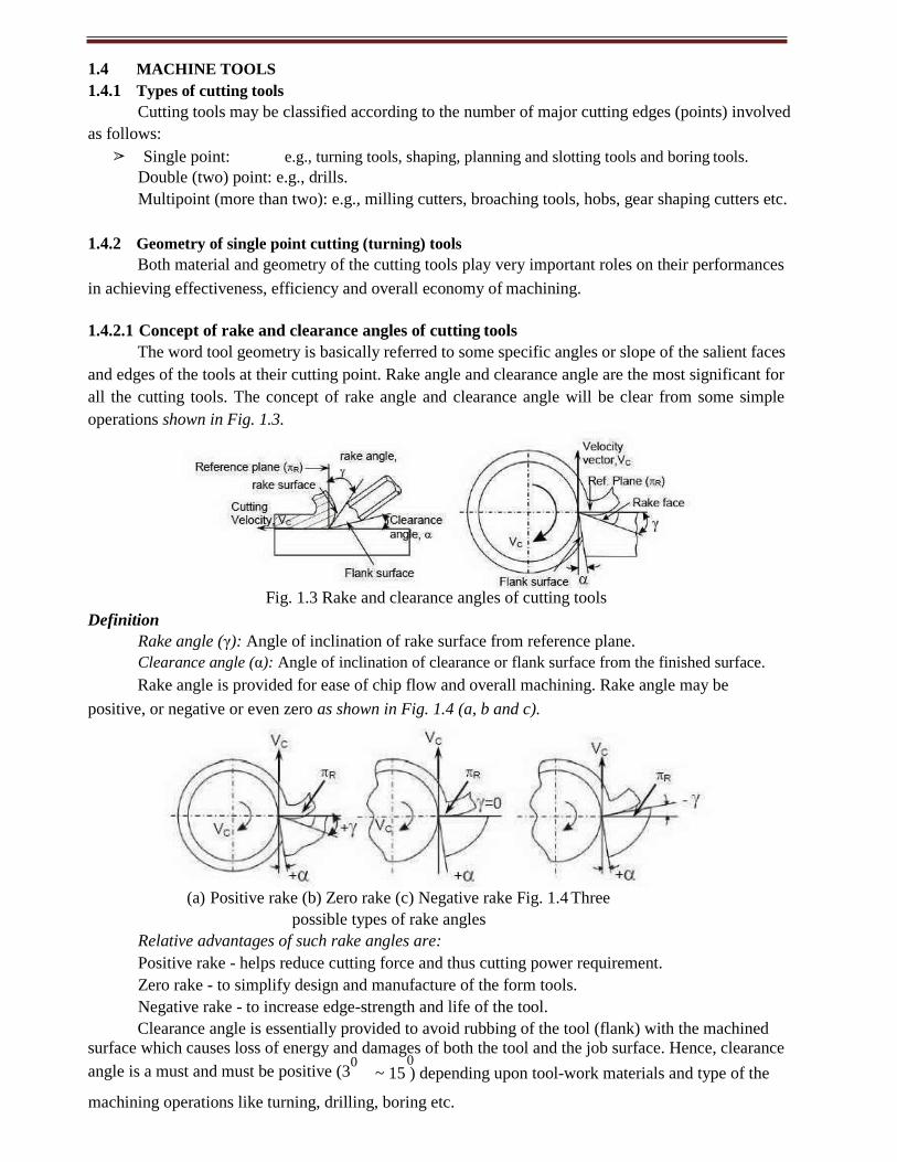
1.4.2.1 Concept of rake and clearance angles of cutting tools
The word tool geometry is basically referred to some specific angles or slope of the salient faces
and edges of the tools at their cutting point. Rake angle and clearance angle are the most significant for
all the cutting tools. The concept of rake angle and clearance angle will be clear from some simple
operations shown in Fig. 1.3.
Fig. 1.3 Rake and clearance angles of cutting tools
Definition
Rake angle (γ): Angle of inclination of rake surface from reference plane.
Clearance angle (α): Angle of inclination of clearance or flank surface from the finished surface.
Rake angle is provided for ease of chip flow and overall machining. Rake angle may be
positive, or negative or even zero as shown in Fig. 1.4 (a, b and c).
(a) Positive rake (b) Zero rake (c) Negative rake Fig. 1.4 Three
possible types of rake angles
Relative advantages of such rake angles are:
Positive rake - helps reduce cutting force and thus cutting power requirement.
Zero rake - to simplify design and manufacture of the form tools.
Negative rake - to increase edge-strength and life of the tool.
Clearance angle is essentially provided to avoid rubbing of the tool (flank) with the machined
surface which causes loss of energy and damages of both the tool and the job surface. Hence, clearance
angle is a must and must be positive (30
0 ~ 15 ) depending upon tool-work materials and type of the
machining operations like turning, drilling, boring etc.
UNIT - I MACHINE TOOLS
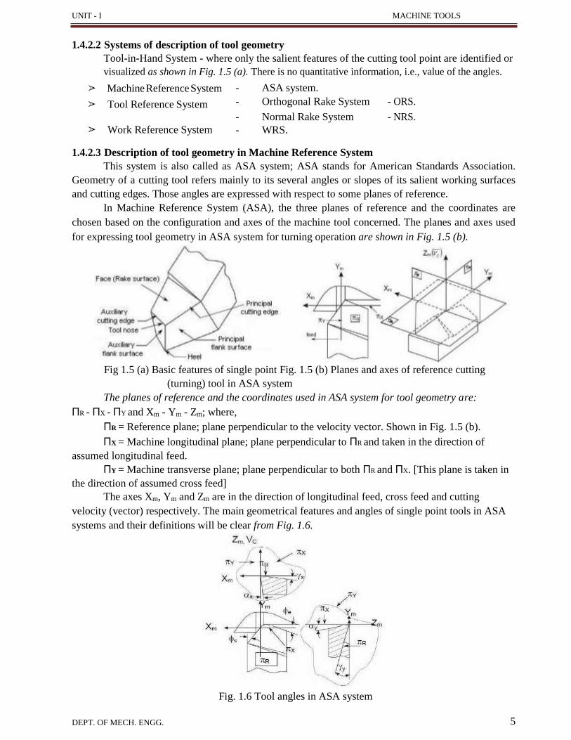
1.4.2.2 Systems of description of tool geometry
Tool-in-Hand System - where only the salient features of the cutting tool point are identified or
visualized as shown in Fig. 1.5 (a). There is no quantitative information, i.e., value of the angles.
➢ Machine Reference System
➢ Tool Reference System
- ASA system.
- Orthogonal Rake System
- ORS.
➢ Work Reference System
- Normal Rake System
- WRS.
- NRS.
1.4.2.3 Description of tool geometry in Machine Reference System
This system is also called as ASA system; ASA stands for American Standards Association.
Geometry of a cutting tool refers mainly to its several angles or slopes of its salient working surfaces
and cutting edges. Those angles are expressed with respect to some planes of reference.
In Machine Reference System (ASA), the three planes of reference and the coordinates are
chosen based on the configuration and axes of the machine tool concerned. The planes and axes used
for expressing tool geometry in ASA system for turning operation are shown in Fig. 1.5 (b).
Fig 1.5 (a) Basic features of single point Fig. 1.5 (b) Planes and axes of reference cutting
(turning) tool in ASA system
The planes of reference and the coordinates used in ASA system for tool geometry are:
ΠR - ΠX - ΠY and Xm - Ym - Zm; where,
ΠR = Reference plane; plane perpendicular to the velocity vector. Shown in Fig. 1.5 (b).
ΠX = Machine longitudinal plane; plane perpendicular to ΠR and taken in the direction of
assumed longitudinal feed.
ΠY = Machine transverse plane; plane perpendicular to both ΠR and ΠX. [This plane is taken in
the direction of assumed cross feed]
The axes Xm, Ym and Zm are in the direction of longitudinal feed, cross feed and cutting
velocity (vector) respectively. The main geometrical features and angles of single point tools in ASA
systems and their definitions will be clear from Fig. 1.6.
Fig. 1.6 Tool angles in ASA system
DEPT. OF MECH. ENGG. 5

UNIT - I MACHINE TOOLS
6
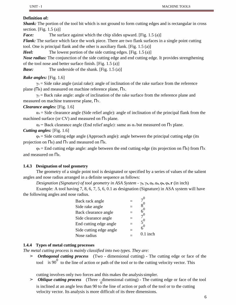
Definition of:
Shank: The portion of the tool bit which is not ground to form cutting edges and is rectangular in cross
section. [Fig. 1.5 (a)]
Face: The surface against which the chip slides upward. [Fig. 1.5 (a)]
Flank: The surface which face the work piece. There are two flank surfaces in a single point cutting
tool. One is principal flank and the other is auxiliary flank. [Fig. 1.5 (a)]
Heel: The lowest portion of the side cutting edges. [Fig. 1.5 (a)]
Nose radius: The conjunction of the side cutting edge and end cutting edge. It provides strengthening
of the tool nose and better surface finish. [Fig. 1.5 (a)]
Base: The underside of the shank. [Fig. 1.5 (a)]
Rake angles: [Fig. 1.6]
γx = Side rake angle (axial rake): angle of inclination of the rake surface from the reference
plane (ΠR) and measured on machine reference plane, ΠX.
γy = Back rake angle: angle of inclination of the rake surface from the reference plane and
measured on machine transverse plane, ΠY.
Clearance angles: [Fig. 1.6]
αx = Side clearance angle (Side relief angle): angle of inclination of the principal flank from the
machined surface (or CV) and measured on ΠX plane.
αy = Back clearance angle (End relief angle): same as αx but measured on ΠY plane.
Cutting angles: [Fig. 1.6]
φs = Side cutting edge angle (Approach angle): angle between the principal cutting edge (its
projection on ΠR) and ΠY and measured on ΠR.
φe = End cutting edge angle: angle between the end cutting edge (its projection on ΠR) from ΠX
and measured on ΠR.
1.4.3 Designation of tool geometry
The geometry of a single point tool is designated or specified by a series of values of the salient
angles and nose radius arranged in a definite sequence as follows:
Designation (Signature) of tool geometry in ASA System - γy, γx, αy, αx, φe, φs, r (in inch)
Example: A tool having 7, 8, 6, 7, 5, 6, 0.1 as designation (Signature) in ASA system will have
the following angles and nose radius.
70
80
60
70
50
60
0.1 inch
1.4.4 Types of metal cutting processes
The metal cutting process is mainly classified into two types. They are:
➢ Orthogonal cutting process (Two - dimensional cutting) - The cutting edge or face of the
tool is 900
to the line of action or path of the tool or to the cutting velocity vector. This
cutting involves only two forces and this makes the analysis simpler. ➢ Oblique cutting process (Three - dimensional cutting) - The cutting edge or face of the tool
0 is inclined at an angle less than 90 to the line of action or path of the tool or to the cutting
velocity vector. Its analysis is more difficult of its three dimensions.
Back rack angle =
Side rake angle =
Back clearance angle =
Side clearance angle =
End cutting edge angle =
Side cutting edge angle =
Nose radius =
7
When λ ρc
0 , the chip flow is deviated from
= 0 and 0 .
0 0
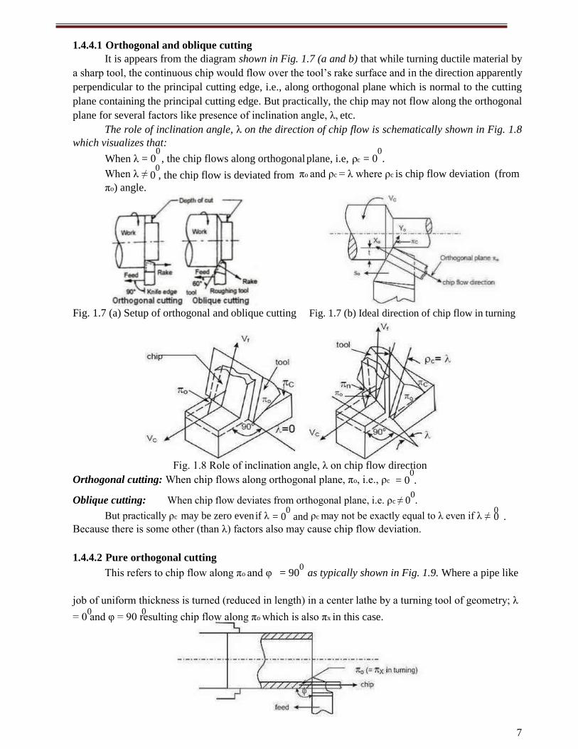
1.4.4.1 Orthogonal and oblique cutting
It is appears from the diagram shown in Fig. 1.7 (a and b) that while turning ductile material by
a sharp tool, the continuous chip would flow over the tool’s rake surface and in the direction apparently
perpendicular to the principal cutting edge, i.e., along orthogonal plane which is normal to the cutting
plane containing the principal cutting edge. But practically, the chip may not flow along the orthogonal
plane for several factors like presence of inclination angle, λ, etc.
The role of inclination angle, λ on the direction of chip flow is schematically shown in Fig. 1.8
which visualizes that: 0 0
= 0 , the chip flows along orthogonal plane, i.e, = 0 .
When λ ≠ 0
πo and ρc = λ where ρc is chip flow deviation (from
πo) angle.
Fig. 1.7 (a) Setup of orthogonal and oblique cutting Fig. 1.7 (b) Ideal direction of chip flow in turning
Fig. 1.8 Role of inclination angle, λ on chip flow direction
Orthogonal cutting: When chip flows along orthogonal plane, πo, i.e., ρc 0
= 0 .
Oblique cutting: When chip flow deviates from orthogonal plane, i.e. ρc ≠ 00.
But practically ρc may be zero even if λ 0
ρc may not be exactly equal to λ even if λ ≠ 0
Because there is some other (than λ) factors also may cause chip flow deviation.
1.4.4.2 Pure orthogonal cutting
This refers to chip flow along πo and φ = 900
as typically shown in Fig. 1.9. Where a pipe like
job of uniform thickness is turned (reduced in length) in a center lathe by a turning tool of geometry; λ
= 0 and φ = 90 resulting chip flow along πo which is also πx in this case.

UNIT - I MACHINE TOOLS
8
Fig. 1.9 Pure orthogonal cutting (pipe turning)
7
1.5 CHIP FORMATION
1.5.1 Mechanism of chip formation
Machining is a semi-finishing or finishing process essentially done to impart required or
stipulated dimensional and form accuracy and surface finish to enable the product to:
Fulfill its basic functional requirements.
Provide better or improved performance.
Render long service life.
Machining is a process of gradual removal of excess material from the preformed blanks in the form of
chips. The form of the chips is an important index of machining because it directly or indirectly indicates:
Nature and behaviour of the work material under machining condition.
Specific energy requirement (amount of energy required to remove unit volume of work
material) in machining work.
Nature and degree of interaction at the chip-tool interfaces.
Work material.
Material and geometry of the cutting tool.
Levels of cutting velocity and feed and also to some extent on depth of cut.
Machining environment or cutting fluid that affects temperature and friction at the chip-tool and
Work-tool interfaces.
Knowledge of basic mechanism(s) of chip formation helps to understand the characteristics of chips
and to attain favourable chip forms.
1.5.1.1 Mechanism of chip formation in machining ductile materials
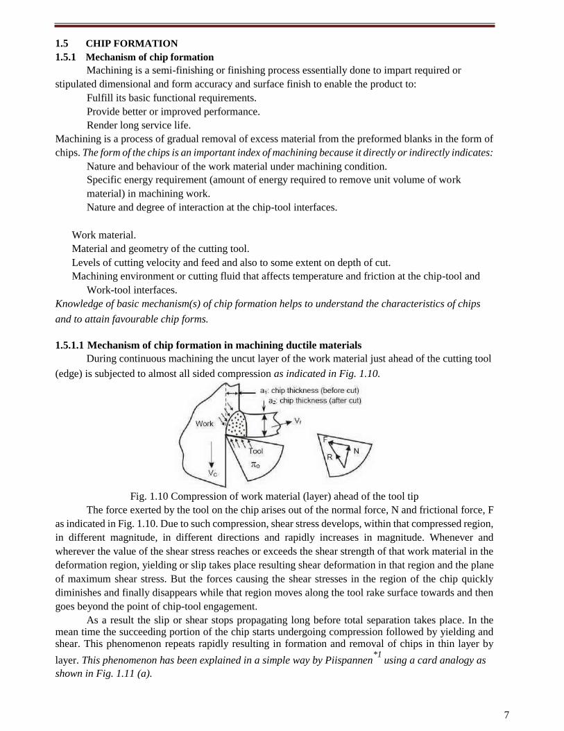
During continuous machining the uncut layer of the work material just ahead of the cutting tool
(edge) is subjected to almost all sided compression as indicated in Fig. 1.10.
Fig. 1.10 Compression of work material (layer) ahead of the tool tip
The force exerted by the tool on the chip arises out of the normal force, N and frictional force, F
as indicated in Fig. 1.10. Due to such compression, shear stress develops, within that compressed region,
in different magnitude, in different directions and rapidly increases in magnitude. Whenever and
wherever the value of the shear stress reaches or exceeds the shear strength of that work material in the
deformation region, yielding or slip takes place resulting shear deformation in that region and the plane
of maximum shear stress. But the forces causing the shear stresses in the region of the chip quickly
diminishes and finally disappears while that region moves along the tool rake surface towards and then
goes beyond the point of chip-tool engagement.
As a result the slip or shear stops propagating long before total separation takes place. In the mean time the succeeding portion of the chip starts undergoing compression followed by yielding and shear. This phenomenon repeats rapidly resulting in formation and removal of chips in thin layer by
layer. This phenomenon has been explained in a simple way by Piispannen*1
using a card analogy as
shown in Fig. 1.11 (a).
UNIT - I MACHINE TOOLS
Fig. 1.13 Pattern of grid deformation during chip formation
9
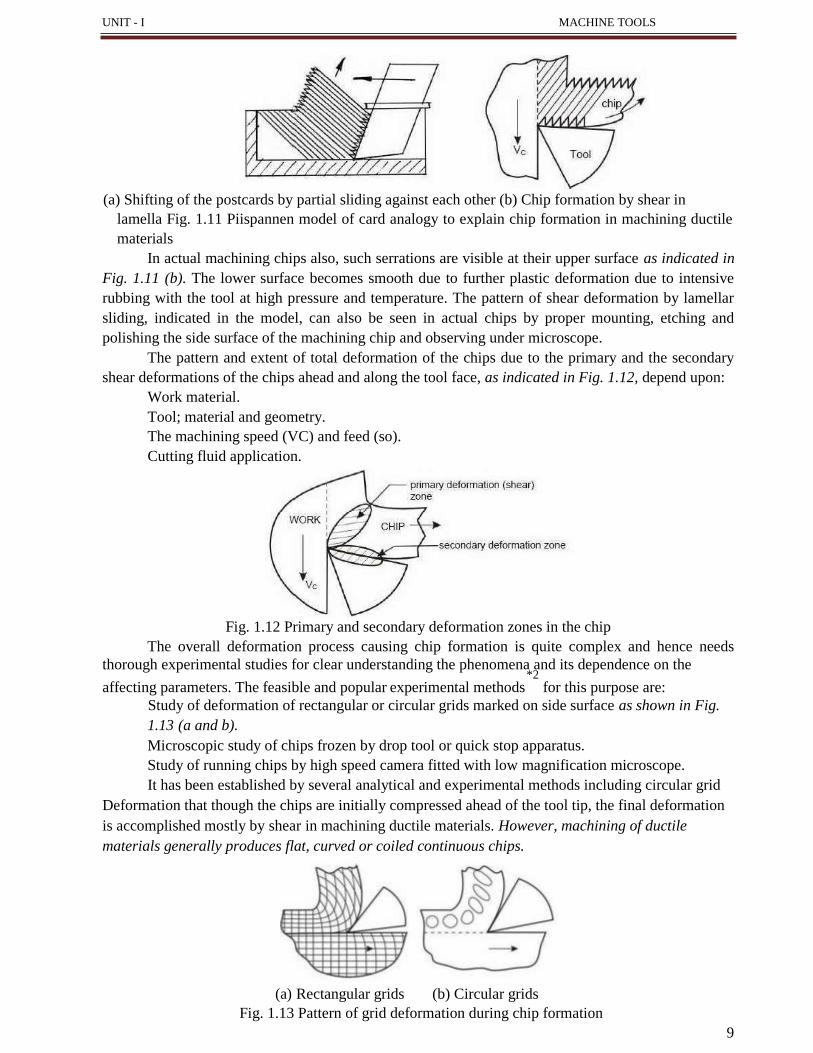
(a) Shifting of the postcards by partial sliding against each other (b) Chip formation by shear in
lamella Fig. 1.11 Piispannen model of card analogy to explain chip formation in machining ductile
materials
In actual machining chips also, such serrations are visible at their upper surface as indicated in
Fig. 1.11 (b). The lower surface becomes smooth due to further plastic deformation due to intensive
rubbing with the tool at high pressure and temperature. The pattern of shear deformation by lamellar
sliding, indicated in the model, can also be seen in actual chips by proper mounting, etching and
polishing the side surface of the machining chip and observing under microscope.
The pattern and extent of total deformation of the chips due to the primary and the secondary
shear deformations of the chips ahead and along the tool face, as indicated in Fig. 1.12, depend upon:
Work material.
Tool; material and geometry.
The machining speed (VC) and feed (so).
Cutting fluid application.
Fig. 1.12 Primary and secondary deformation zones in the chip
The overall deformation process causing chip formation is quite complex and hence needs
thorough experimental studies for clear understanding the phenomena and its dependence on the *2
affecting parameters. The feasible and popular experimental methods for this purpose are:
Study of deformation of rectangular or circular grids marked on side surface as shown in Fig.
1.13 (a and b).
Microscopic study of chips frozen by drop tool or quick stop apparatus.
Study of running chips by high speed camera fitted with low magnification microscope.
It has been established by several analytical and experimental methods including circular grid
Deformation that though the chips are initially compressed ahead of the tool tip, the final deformation
is accomplished mostly by shear in machining ductile materials. However, machining of ductile
materials generally produces flat, curved or coiled continuous chips.
(a) Rectangular grids (b) Circular grids

10
1.5.1.2 Mechanism of chip formation in machining brittle materials
The basic two mechanisms involved in chip formation are:
Yielding - generally for ductile materials.
Brittle fracture - generally for brittle materials.
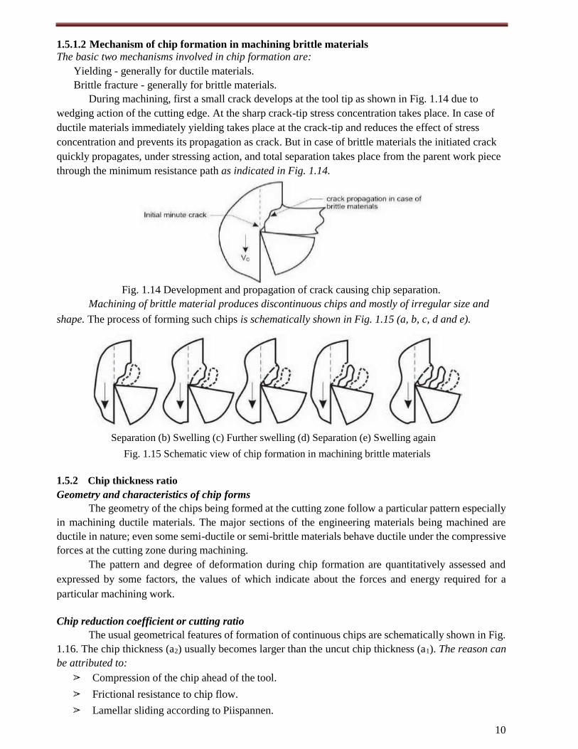
During machining, first a small crack develops at the tool tip as shown in Fig. 1.14 due to
wedging action of the cutting edge. At the sharp crack-tip stress concentration takes place. In case of
ductile materials immediately yielding takes place at the crack-tip and reduces the effect of stress
concentration and prevents its propagation as crack. But in case of brittle materials the initiated crack
quickly propagates, under stressing action, and total separation takes place from the parent work piece
through the minimum resistance path as indicated in Fig. 1.14.
Fig. 1.14 Development and propagation of crack causing chip separation.
Machining of brittle material produces discontinuous chips and mostly of irregular size and
shape. The process of forming such chips is schematically shown in Fig. 1.15 (a, b, c, d and e).
Separation (b) Swelling (c) Further swelling (d) Separation (e) Swelling again
Fig. 1.15 Schematic view of chip formation in machining brittle materials
1.5.2 Chip thickness ratio
Geometry and characteristics of chip forms
The geometry of the chips being formed at the cutting zone follow a particular pattern especially
in machining ductile materials. The major sections of the engineering materials being machined are
ductile in nature; even some semi-ductile or semi-brittle materials behave ductile under the compressive
forces at the cutting zone during machining.
The pattern and degree of deformation during chip formation are quantitatively assessed and
expressed by some factors, the values of which indicate about the forces and energy required for a
particular machining work.
Chip reduction coefficient or cutting ratio
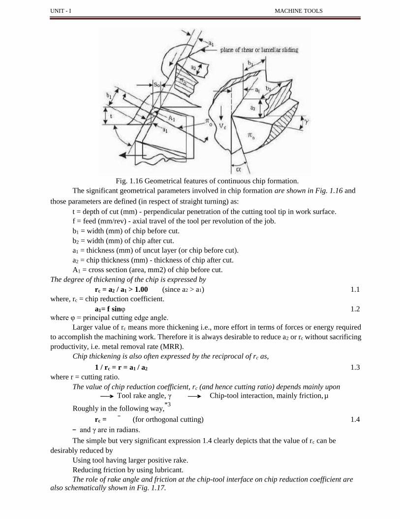
The usual geometrical features of formation of continuous chips are schematically shown in Fig.
1.16. The chip thickness (a2) usually becomes larger than the uncut chip thickness (a1). The reason can
be attributed to:
➢ Compression of the chip ahead of the tool.
➢ Frictional resistance to chip flow.
➢ Lamellar sliding according to Piispannen.
UNIT - I MACHINE TOOLS
Fig. 1.16 Geometrical features of continuous chip formation.
The significant geometrical parameters involved in chip formation are shown in Fig. 1.16 and
those parameters are defined (in respect of straight turning) as:
t = depth of cut (mm) - perpendicular penetration of the cutting tool tip in work surface.
f = feed (mm/rev) - axial travel of the tool per revolution of the job.
b1 = width (mm) of chip before cut.
b2 = width (mm) of chip after cut.
a1 = thickness (mm) of uncut layer (or chip before cut).
a2 = chip thickness (mm) - thickness of chip after cut.
A1 = cross section (area, mm2) of chip before cut.
The degree of thickening of the chip is expressed by
rc = a2 / a1 > 1.00 (since a2 > a1) 1.1
where, rc = chip reduction coefficient.
a1= f sinφ 1.2
where φ = principal cutting edge angle.
Larger value of rc means more thickening i.e., more effort in terms of forces or energy required
to accomplish the machining work. Therefore it is always desirable to reduce a2 or rc without sacrificing
productivity, i.e. metal removal rate (MRR).
Chip thickening is also often expressed by the reciprocal of rc as,
1 / rc = r = a1 / a2 1.3
where r = cutting ratio.
The value of chip reduction coefficient, rc (and hence cutting ratio) depends mainly upon
Tool rake angle, γ Chip-tool interaction, mainly friction, µ
Roughly in the following way,*3
rc = (for orthogonal cutting) 1.4
and γ are in radians.
The simple but very significant expression 1.4 clearly depicts that the value of rc can be
desirably reduced by
Using tool having larger positive rake.
Reducing friction by using lubricant.
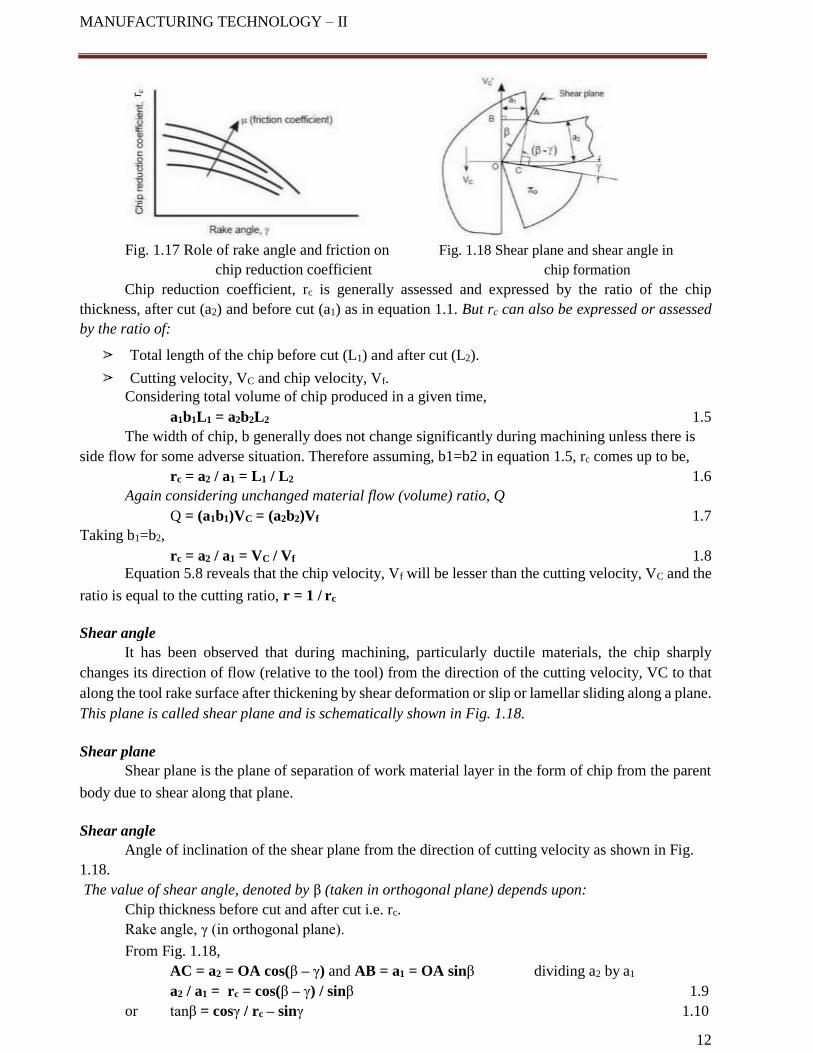
The role of rake angle and friction at the chip-tool interface on chip reduction coefficient are also schematically shown in Fig. 1.17.
12
MANUFACTURING TECHNOLOGY – II
Fig. 1.17 Role of rake angle and friction on Fig. 1.18 Shear plane and shear angle in
chip reduction coefficient chip formation
Chip reduction coefficient, rc is generally assessed and expressed by the ratio of the chip
thickness, after cut (a2) and before cut (a1) as in equation 1.1. But rc can also be expressed or assessed
by the ratio of:
➢ Total length of the chip before cut (L1) and after cut (L2).
➢ Cutting velocity, VC and chip velocity, Vf.
Considering total volume of chip produced in a given time,
a1b1L1 = a2b2L2 1.5
The width of chip, b generally does not change significantly during machining unless there is
side flow for some adverse situation. Therefore assuming, b1=b2 in equation 1.5, rc comes up to be,
rc = a2 / a1 = L1 / L2 1.6
Again considering unchanged material flow (volume) ratio, Q
Q = (a1b1)VC = (a2b2)Vf 1.7
Taking b1=b2,
rc = a2 / a1 = VC / Vf 1.8
Equation 5.8 reveals that the chip velocity, Vf will be lesser than the cutting velocity, VC and the
ratio is equal to the cutting ratio, r = 1 / rc
Shear angle
It has been observed that during machining, particularly ductile materials, the chip sharply
changes its direction of flow (relative to the tool) from the direction of the cutting velocity, VC to that
along the tool rake surface after thickening by shear deformation or slip or lamellar sliding along a plane.
This plane is called shear plane and is schematically shown in Fig. 1.18.
Shear plane
Shear plane is the plane of separation of work material layer in the form of chip from the parent
body due to shear along that plane.
Shear angle
Angle of inclination of the shear plane from the direction of cutting velocity as shown in Fig.
1.18.
The value of shear angle, denoted by β (taken in orthogonal plane) depends upon:
Chip thickness before cut and after cut i.e. rc.
Rake angle, γ (in orthogonal plane).
From Fig. 1.18,
AC = a2 = OA cos(β – γ) and AB = a1 = OA sinβ dividing a2 by a1
a2 / a1 = rc = cos(β – γ) / sinβ 1.9
or tanβ = cosγ / rc – sinγ 1.10

UNIT - I MACHINE TOOLS
Replacing chip reduction coefficient, rc by cutting ratio, r, the equation 1.10 changes to,
tanβ = rcosγ / 1 – rsinγ 1.11 Equation 1.10 depicts that with the increase in
rc, shear angle decreases and vice-versa. It is also evident from equation 1.10 as well as equation 1.4
that shear angle increases both directly and indirectly with the increase in tool rake angle. Increase in
shear angle means more favorable machining condition
requiring lesser specific energy.
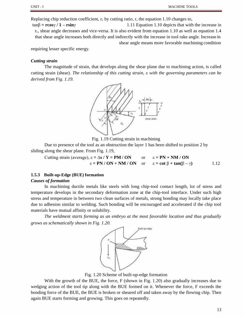
Cutting strain
The magnitude of strain, that develops along the shear plane due to machining action, is called
cutting strain (shear). The relationship of this cutting strain, ε with the governing parameters can be
derived from Fig. 1.19.
Fig. 1.19 Cutting strain in machining
Due to presence of the tool as an obstruction the layer 1 has been shifted to position 2 by
sliding along the shear plane. From Fig. 1.19,
Cutting strain (average), ε = ∆s / Y = PM / ON or ε = PN + NM / ON
ε = PN / ON + NM / ON or ε = cot β + tan(β – γ) 1.12
1.5.3 Built-up-Edge (BUE) formation
Causes of formation
In machining ductile metals like steels with long chip-tool contact length, lot of stress and
temperature develops in the secondary deformation zone at the chip-tool interface. Under such high
stress and temperature in between two clean surfaces of metals, strong bonding may locally take place
due to adhesion similar to welding. Such bonding will be encouraged and accelerated if the chip tool
materials have mutual affinity or solubility.
The weldment starts forming as an embryo at the most favorable location and thus gradually
grows as schematically shown in Fig. 1.20.
Fig. 1.20 Scheme of built-up-edge formation
With the growth of the BUE, the force, F (shown in Fig. 1.20) also gradually increases due to
wedging action of the tool tip along with the BUE formed on it. Whenever the force, F exceeds the
bonding force of the BUE, the BUE is broken or sheared off and taken away by the flowing chip. Then
again BUE starts forming and growing. This goes on repeatedly.
13
Characteristics of BUE
Built-up-edges are characterized by its shape, size and bond strength, which depend upon:
Work tool materials.
Stress and temperature, i.e., cutting velocity and feed.
Cutting fluid application governing cooling and lubrication.
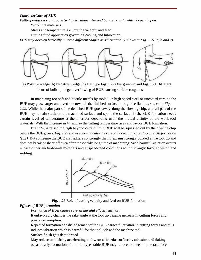
BUE may develop basically in three different shapes as schematically shown in Fig. 1.21 (a, b and c).
(a) Positive wedge (b) Negative wedge (c) Flat type Fig. 1.22 Overgrowing and Fig. 1.21 Different
forms of built-up-edge. overflowing of BUE causing surface roughness
In machining too soft and ductile metals by tools like high speed steel or uncoated carbide the
BUE may grow larger and overflow towards the finished surface through the flank as shown in Fig.
1.22. While the major part of the detached BUE goes away along the flowing chip, a small part of the
BUE may remain stuck on the machined surface and spoils the surface finish. BUE formation needs
certain level of temperature at the interface depending upon the mutual affinity of the work-tool
materials. With the increase in VC and so the cutting temperature rises and favors BUE formation.
But if VC is raised too high beyond certain limit, BUE will be squashed out by the flowing chip
before the BUE grows. Fig. 1.23 shows schematically the role of increasing VC and so on BUE formation
(size). But sometime the BUE may adhere so strongly that it remains strongly bonded at the tool tip and
does not break or shear off even after reasonably long time of machining. Such harmful situation occurs
in case of certain tool-work materials and at speed-feed conditions which strongly favor adhesion and
welding.
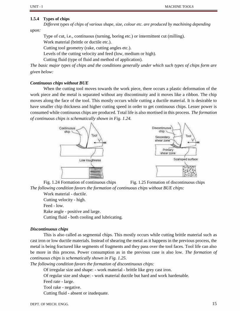
Fig. 1.23 Role of cutting velocity and feed on BUE formation
Effects of BUE formation
Formation of BUE causes several harmful effects, such as:
It unfavorably changes the rake angle at the tool tip causing increase in cutting forces and
power consumption.
Repeated formation and dislodgement of the BUE causes fluctuation in cutting forces and thus
induces vibration which is harmful for the tool, job and the machine tool.
Surface finish gets deteriorated.
May reduce tool life by accelerating tool-wear at its rake surface by adhesion and flaking
occasionally, formation of thin flat type stable BUE may reduce tool wear at the rake face.
14
UNIT - I MACHINE TOOLS
1.5.4 Types of chips
Different types of chips of various shape, size, colour etc. are produced by machining depending
upon:
Type of cut, i.e., continuous (turning, boring etc.) or intermittent cut (milling).
Work material (brittle or ductile etc.).
Cutting tool geometry (rake, cutting angles etc.).
Levels of the cutting velocity and feed (low, medium or high).
Cutting fluid (type of fluid and method of application).
The basic major types of chips and the conditions generally under which such types of chips form are
given below:
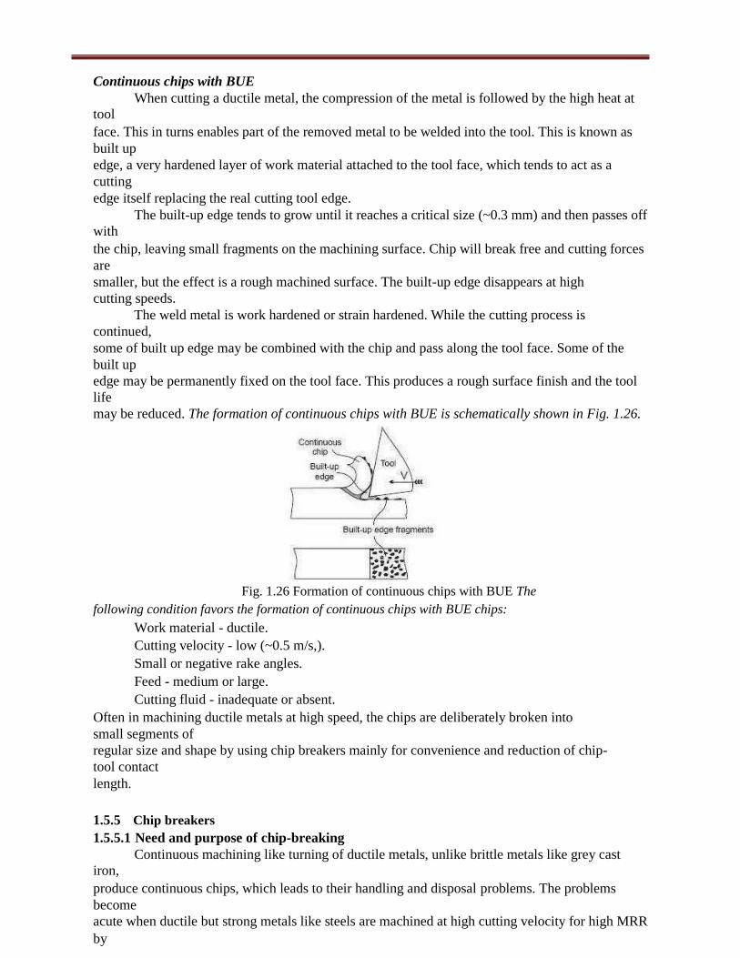
Continuous chips without BUE
When the cutting tool moves towards the work piece, there occurs a plastic deformation of the
work piece and the metal is separated without any discontinuity and it moves like a ribbon. The chip
moves along the face of the tool. This mostly occurs while cutting a ductile material. It is desirable to
have smaller chip thickness and higher cutting speed in order to get continuous chips. Lesser power is
consumed while continuous chips are produced. Total life is also mortised in this process. The formation
of continuous chips is schematically shown in Fig. 1.24.
Fig. 1.24 Formation of continuous chips Fig. 1.25 Formation of discontinuous chips
The following condition favors the formation of continuous chips without BUE chips:
Work material - ductile.
Cutting velocity - high.
Feed - low.
Rake angle - positive and large.
Cutting fluid - both cooling and lubricating.
Discontinuous chips
This is also called as segmental chips. This mostly occurs while cutting brittle material such as
cast iron or low ductile materials. Instead of shearing the metal as it happens in the previous process, the
metal is being fractured like segments of fragments and they pass over the tool faces. Tool life can also
be more in this process. Power consumption as in the previous case is also low. The formation of
continuous chips is schematically shown in Fig. 1.25.
The following condition favors the formation of discontinuous chips:
Of irregular size and shape: - work material - brittle like grey cast iron.
Of regular size and shape: - work material ductile but hard and work hardenable.
Feed rate - large.
Tool rake - negative.
Cutting fluid - absent or inadequate.
DEPT. OF MECH. ENGG. 15
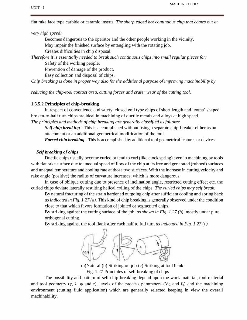
Continuous chips with BUE
When cutting a ductile metal, the compression of the metal is followed by the high heat at
tool
face. This in turns enables part of the removed metal to be welded into the tool. This is known as
built up
edge, a very hardened layer of work material attached to the tool face, which tends to act as a
cutting
edge itself replacing the real cutting tool edge.
The built-up edge tends to grow until it reaches a critical size (~0.3 mm) and then passes off
with
the chip, leaving small fragments on the machining surface. Chip will break free and cutting forces
are
smaller, but the effect is a rough machined surface. The built-up edge disappears at high
cutting speeds.
The weld metal is work hardened or strain hardened. While the cutting process is
continued,
some of built up edge may be combined with the chip and pass along the tool face. Some of the
built up
edge may be permanently fixed on the tool face. This produces a rough surface finish and the tool
life
may be reduced. The formation of continuous chips with BUE is schematically shown in Fig. 1.26.
Fig. 1.26 Formation of continuous chips with BUE The
following condition favors the formation of continuous chips with BUE chips:
Work material - ductile.
Cutting velocity - low (~0.5 m/s,).
Small or negative rake angles.
Feed - medium or large.
Cutting fluid - inadequate or absent.
Often in machining ductile metals at high speed, the chips are deliberately broken into
small segments of
regular size and shape by using chip breakers mainly for convenience and reduction of chip-
tool contact
length.
1.5.5 Chip breakers
1.5.5.1 Need and purpose of chip-breaking
Continuous machining like turning of ductile metals, unlike brittle metals like grey cast
iron,
produce continuous chips, which leads to their handling and disposal problems. The problems
become
acute when ductile but strong metals like steels are machined at high cutting velocity for high MRR
by

16
UNIT - I MACHINE TOOLS
flat rake face type carbide or ceramic inserts. The sharp edged hot continuous chip that comes out at
very high speed:
Becomes dangerous to the operator and the other people working in the vicinity.
May impair the finished surface by entangling with the rotating job.
Creates difficulties in chip disposal.
Therefore it is essentially needed to break such continuous chips into small regular pieces for:
Safety of the working people.
Prevention of damage of the product.
Easy collection and disposal of chips.
Chip breaking is done in proper way also for the additional purpose of improving machinability by
reducing the chip-tool contact area, cutting forces and crater wear of the cutting tool.
1.5.5.2 Principles of chip-breaking
In respect of convenience and safety, closed coil type chips of short length and ‘coma’ shaped
broken-to-half turn chips are ideal in machining of ductile metals and alloys at high speed.
The principles and methods of chip breaking are generally classified as follows:
Self chip breaking - This is accomplished without using a separate chip-breaker either as an
attachment or an additional geometrical modification of the tool.
Forced chip breaking - This is accomplished by additional tool geometrical features or devices.
Self breaking of chips
Ductile chips usually become curled or tend to curl (like clock spring) even in machining by tools
with flat rake surface due to unequal speed of flow of the chip at its free and generated (rubbed) surfaces
and unequal temperature and cooling rate at those two surfaces. With the increase in cutting velocity and
rake angle (positive) the radius of curvature increases, which is more dangerous.
In case of oblique cutting due to presence of inclination angle, restricted cutting effect etc. the
curled chips deviate laterally resulting helical coiling of the chips. The curled chips may self break:
By natural fracturing of the strain hardened outgoing chip after sufficient cooling and spring back
as indicated in Fig. 1.27 (a). This kind of chip breaking is generally observed under the condition
close to that which favors formation of jointed or segmented chips.
By striking against the cutting surface of the job, as shown in Fig. 1.27 (b), mostly under pure
orthogonal cutting.
By striking against the tool flank after each half to full turn as indicated in Fig. 1.27 (c).
(a) Natural (b) Striking on job (c) Striking at tool flank
Fig. 1.27 Principles of self breaking of chips
The possibility and pattern of self chip-breaking depend upon the work material, tool material
and tool geometry (γ, λ, φ and r), levels of the process parameters (VC and fo) and the machining
environment (cutting fluid application) which are generally selected keeping in view the overall
machinability.
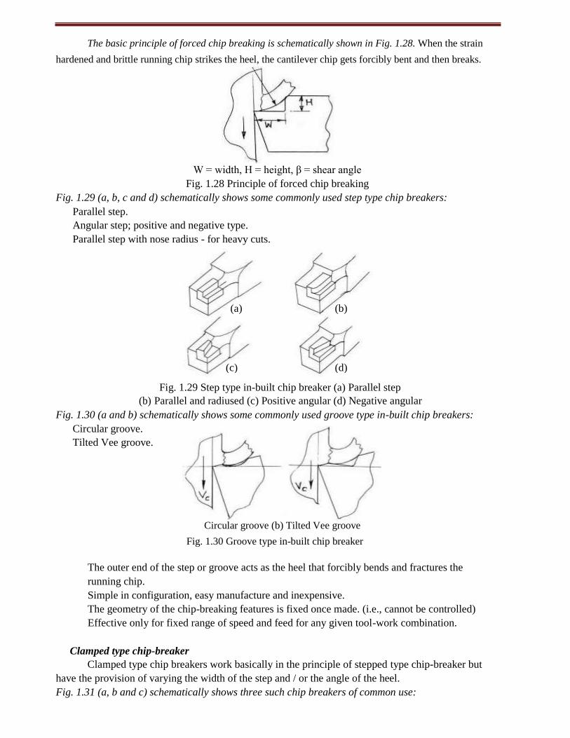
The basic principle of forced chip breaking is schematically shown in Fig. 1.28. When the strain
hardened and brittle running chip strikes the heel, the cantilever chip gets forcibly bent and then breaks.
W = width, H = height, β = shear angle
Fig. 1.28 Principle of forced chip breaking
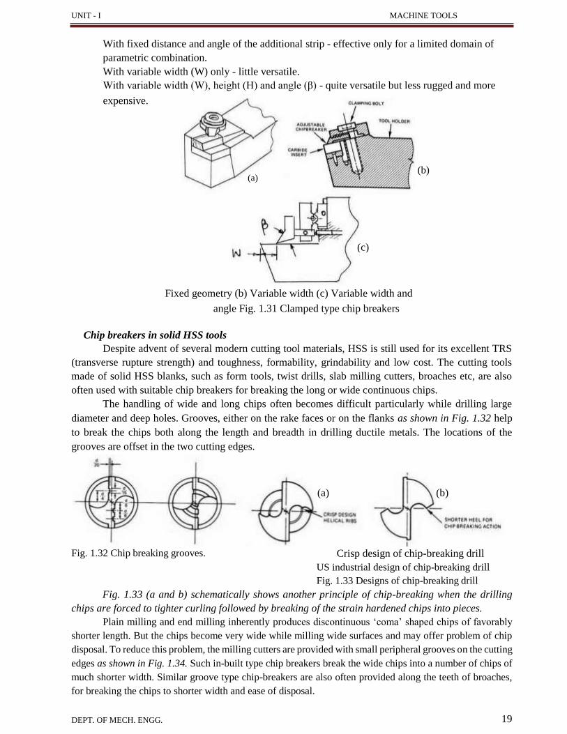
Fig. 1.29 (a, b, c and d) schematically shows some commonly used step type chip breakers:
Parallel step.
Angular step; positive and negative type.
Parallel step with nose radius - for heavy cuts.
Fig. 1.29 Step type in-built chip breaker (a) Parallel step
(b) Parallel and radiused (c) Positive angular (d) Negative angular
Fig. 1.30 (a and b) schematically shows some commonly used groove type in-built chip breakers:
Circular groove.
Tilted Vee groove.
Circular groove (b) Tilted Vee groove
Fig. 1.30 Groove type in-built chip breaker
The outer end of the step or groove acts as the heel that forcibly bends and fractures the
running chip.
Simple in configuration, easy manufacture and inexpensive.
The geometry of the chip-breaking features is fixed once made. (i.e., cannot be controlled)
Effective only for fixed range of speed and feed for any given tool-work combination.
Clamped type chip-breaker
Clamped type chip breakers work basically in the principle of stepped type chip-breaker but
have the provision of varying the width of the step and / or the angle of the heel.
Fig. 1.31 (a, b and c) schematically shows three such chip breakers of common use:
(a) (b)
(c) (d)
UNIT - I MACHINE TOOLS
19 DEPT. OF MECH. ENGG.
(b) (a)
(c)
With fixed distance and angle of the additional strip - effective only for a limited domain of
parametric combination.
With variable width (W) only - little versatile.
With variable width (W), height (H) and angle (β) - quite versatile but less rugged and more
expensive.
Fixed geometry (b) Variable width (c) Variable width and
angle Fig. 1.31 Clamped type chip breakers
Chip breakers in solid HSS tools
Despite advent of several modern cutting tool materials, HSS is still used for its excellent TRS
(transverse rupture strength) and toughness, formability, grindability and low cost. The cutting tools
made of solid HSS blanks, such as form tools, twist drills, slab milling cutters, broaches etc, are also
often used with suitable chip breakers for breaking the long or wide continuous chips.
The handling of wide and long chips often becomes difficult particularly while drilling large
diameter and deep holes. Grooves, either on the rake faces or on the flanks as shown in Fig. 1.32 help
to break the chips both along the length and breadth in drilling ductile metals. The locations of the
grooves are offset in the two cutting edges.
Fig. 1.32 Chip breaking grooves. Crisp design of chip-breaking drill
US industrial design of chip-breaking drill
Fig. 1.33 Designs of chip-breaking drill
Fig. 1.33 (a and b) schematically shows another principle of chip-breaking when the drilling
chips are forced to tighter curling followed by breaking of the strain hardened chips into pieces.
Plain milling and end milling inherently produces discontinuous ‘coma’ shaped chips of favorably
shorter length. But the chips become very wide while milling wide surfaces and may offer problem of chip
disposal. To reduce this problem, the milling cutters are provided with small peripheral grooves on the cutting
edges as shown in Fig. 1.34. Such in-built type chip breakers break the wide chips into a number of chips of
much shorter width. Similar groove type chip-breakers are also often provided along the teeth of broaches,
for breaking the chips to shorter width and ease of disposal.
(a) (b)
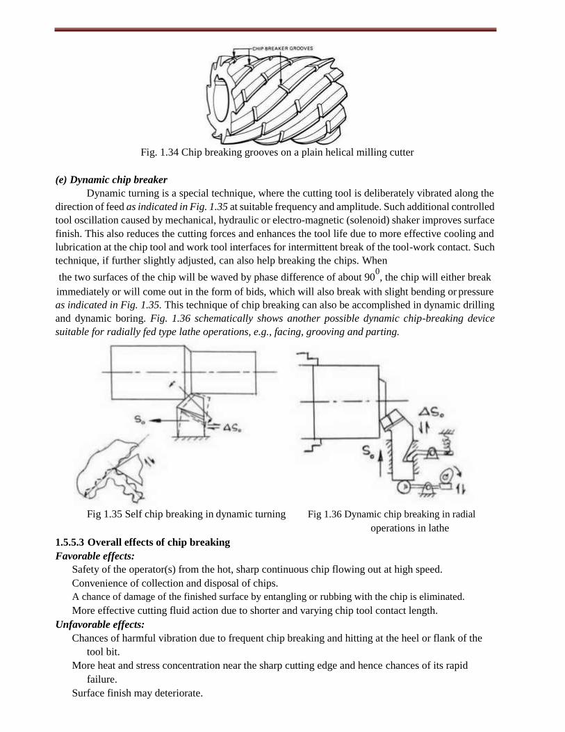
Fig. 1.34 Chip breaking grooves on a plain helical milling cutter
(e) Dynamic chip breaker
Dynamic turning is a special technique, where the cutting tool is deliberately vibrated along the
direction of feed as indicated in Fig. 1.35 at suitable frequency and amplitude. Such additional controlled
tool oscillation caused by mechanical, hydraulic or electro-magnetic (solenoid) shaker improves surface
finish. This also reduces the cutting forces and enhances the tool life due to more effective cooling and
lubrication at the chip tool and work tool interfaces for intermittent break of the tool-work contact. Such
technique, if further slightly adjusted, can also help breaking the chips. When
the two surfaces of the chip will be waved by phase difference of about 900, the chip will either break
immediately or will come out in the form of bids, which will also break with slight bending or pressure
as indicated in Fig. 1.35. This technique of chip breaking can also be accomplished in dynamic drilling
and dynamic boring. Fig. 1.36 schematically shows another possible dynamic chip-breaking device
suitable for radially fed type lathe operations, e.g., facing, grooving and parting.
Fig 1.35 Self chip breaking in dynamic turning Fig 1.36 Dynamic chip breaking in radial
operations in lathe
1.5.5.3 Overall effects of chip breaking
Favorable effects:
Safety of the operator(s) from the hot, sharp continuous chip flowing out at high speed.
Convenience of collection and disposal of chips.
A chance of damage of the finished surface by entangling or rubbing with the chip is eliminated.
More effective cutting fluid action due to shorter and varying chip tool contact length.
Unfavorable effects:
Chances of harmful vibration due to frequent chip breaking and hitting at the heel or flank of the
tool bit.
More heat and stress concentration near the sharp cutting edge and hence chances of its rapid
failure.
Surface finish may deteriorate.
UNIT - I MACHINE TOOLS
21 DEPT. OF MECH. ENGG.
1.6 ORTHOGONAL METAL CUTTING
1.6.1 Benefit of knowing and purpose of determining cutting forces
The aspects of the cutting forces concerned:
Magnitude of the cutting forces and their components.
Directions and locations of action of those forces.
Pattern of the forces: static and / or dynamic.
Estimation of cutting power consumption, which also enables selection of the power source(s)
during design of the machine tools.
Structural design of the machine - fixture - tool system.
Evaluation of role of the various machining parameters (process - VC, fo, t, tool - material and
geometry, environment - cutting fluid) on cutting forces.
Study of behaviour and machinability characterization of the work materials.
Condition monitoring of the cutting tools and machine tools.
1.6.2 Cutting force components and their significances
The single point cutting tools being used for turning, shaping, planing, slotting, boring etc. are
characterized by having only one cutting force during machining. But that force is resolved into two or
three components for ease of analysis and exploitation. Fig. 1.37 visualizes how the single cutting force
in turning is resolved into three components along the three orthogonal directions; X, Y and Z.
The resolution of the force components in turning can be more conveniently understood from
their display in 2-D as shown in Fig. 1.38.
Fig. 1.37 Cutting force R resolved into PX, PY and PZ Fig. 1.38 turning force resolved into PZ, PX and PY
The resultant cutting force, R is resolved as,
R = PZ + PXY 1.13
and PXY = PX + PY 1.14
where, PX = PXY sinφ 1.15
and PY = PXY cosφ 1.16
PZ - Tangential component taken in the direction of Zm axis.
PX - Axial component taken in the direction of longitudinal feed or Xm axis.
PY - Radial or transverse component taken along Ym axis.
In Fig. 1.37 and Fig. 1.38 the force components are shown to be acting on the tool. A similar set of
forces also act on the job at the cutting point but in opposite directions as indicated by PZ', PXY', PX'
and PY' in Fig. 1.38.
22
Significance of PZ, PX and PY
PZ: Called the main or major component as it is the largest in magnitude. It is also called power
component as it being acting along and being multiplied by VC decides cutting power (PZ.VC)
consumption.
PY: May not be that large in magnitude but is responsible for causing dimensional inaccuracy and
vibration.
PX: It, even if larger than PY, is least harmful and hence least significant.
1.6.3 Merchant’s Circle Diagram and its use
In orthogonal cutting when the chip flows along the orthogonal plane, π0, the cutting force
(resultant) and its components PZ and PXY remain in the orthogonal plane. Fig. 1.39 is schematically
showing the forces acting on a piece of continuous chip coming out from the shear zone at a constant
speed. That chip is apparently in a state of equilibrium.
Fig 1.39 Development of Merchant’s
circle diagram
The forces in the chip segment are:
From job-side:
Fig. 1.40 Merchant’s Circle Diagram
with cutting forces
Ps - Shear force.
Pn - force normal to the shear force.
From the tool side:
▪ R1 = R (in state of equilibrium) where, R1 = F + N
N - Force normal to rake face.
F - Friction force at chip tool interface.
R1 = PZ + PXY where, PZ - Force along the velocity vector.
PXY - force along orthogonal plane.
The circle(s) drawn taking R or R1 as diameter is called Merchant’s circle which contains all the force
components concerned as intercepts. The two circles with their forces are combined into one circle having all the
forces contained in that as shown by the diagram called Merchant’s Circle Diagram
(MCD) in Fig. 1.40.
The significance of the forces displayed in the Merchant’s Circle Diagram is:
Ps - The shear force essentially required to produce or separate the chip from the parent body by shear.
Pn - Inherently exists along with Ps.
F - Friction force at the chip tool interface.
UNIT - I MACHINE TOOLS
23 DEPT. OF MECH. ENGG.
N - Force acting normal to the rake surface.
PZ = PXY – PX + PY = main force or power component acting in the direction of cutting velocity.
The magnitude of PS provides the yield shear strength of the work material under the cutting
action. The values of F and the ratio of F and N indicate the nature and degree of interaction like friction
at the chip tool interface. The force components PX, PY, PZ are generally obtained by direct measurement.
Again PZ helps in determining cutting power and specific energy requirement. The force components
are also required to design the cutting tool and the machine tool.
1.6.4 Advantageous use of Merchant’s circle diagram
Proper use of MCD enables the followings:
Easy, quick and reasonably accurate determination of several other forces from a few known
forces involved in machining.
Friction at chip tool interface and dynamic yield shear strength can be easily determined.
Equations relating the different forces are easily developed.
Merchant’s circle diagram (MCD) is only valid for orthogonal cutting.
By the ratio, F/N, the MCD gives apparent (not actual) coefficient of friction.
It is based on single shear plane theory.
1.6.5 Development of equations for estimation of cutting forces
The two basic methods of determination of cutting forces and their characteristics are:
Analytical method: Enables estimation of cutting forces.
Characteristics:
Easy, quick and inexpensive.
Very approximate and average.
Effect of several factors like cutting velocity, cutting fluid action etc. are not revealed.
Unable to depict the dynamic characteristics of the forces.
Experimental methods: Direct measurement.
Quite accurate and provides true picture.
Can reveal effect of variation of any parameter on the forces.
Depicts both static and dynamic parts of the forces.
Needs measuring facilities, expertise and hence expensive.
The equations for analytical estimation of the salient cutting force components are conveniently
developed using Merchant’s Circle Diagram (MCD) when it is orthogonal cutting by any single point
cutting tool like, in turning, shaping, planing, boring etc.
1.6.6 Development of mathematical expressions for cutting forces
Tangential or main component, PZ
This can be very conveniently done by using Merchant’s Circle Diagram, as shown in Fig.
1.40. From the MCD shown in Fig. 1.40,
PZ = Rcos(η – γ) 1.17
Ps = Rcos(β + η – γ) 1.18
Dividing Eqn. 1.17 by Eqn. 1.18,
PZ = Ps cos(η – γ) / cos(β + η – γ) 1.19
It was already shown that, Ps = t.f. τs / sinβ 1.20
where, τs - Dynamic yield shear strength of the work material. Thus, PZ = t.f. τs cos(η – γ) / sinβ cos(β + η – γ) 1.21
24
= 90 and For brittle work materials, like grey cast iron, usually, 2β + η – γ 0
τs remains almost
unchanged. Then for turning brittle material,
PZ = t.f. τs cos(900
– 2β) / sinβ cos(900
– β) 1.22
orPZ = 2 t.f. τs cotβ 1.23
Where, cotβ = rc – tanγ
rc = a2 / a1 = a2 / f sinφ
It is difficult to measure chip thickness and evaluate the values of ζ while machining brittle materials and
the value of τs is roughly estimated from
τs = 0.175 BHN 1.24
where, BHN - Brinnel’s Hardness number. But most of the engineering materials are ductile in nature and even some semi-brittle materials
behave ductile under the cutting condition. The angle relationship reasonably accurately applicable for
ductile metals is
β + η – γ = 450
1.25
and the value of τs is obtained from, τs = 0.186 BHN (approximate) 1.26
or τs = 0.74σuε0.6O
(more suitable and accurate) 1.27
where, σu - Ultimate tensile strength of the work material
ε - Cutting strain, ε ≅ rc – tanγ
- % elongation
Substituting Eqn. 1.25 in Eqn. 1.21,
PZ = t.f. τs(cot β + 1) 1.28
Again cotβ ≅ rc – tanγ
So, PZ = t.f.τs(rc – tanγ + 1) 1.29
Axial force, PX and transverse force, PY
From the MCD shown in Fig. 1.40,
PXY = PZ tan(η – γ) 1.30
Combining Eqn. 1.21 and Eqn. 1.30, PXY = t.f.τs sin(η – γ) / sinβ cos(β + η – γ) 1.31
Again, using the angle relationship β + η – γ 0
= 45 , for ductile material
PXY = t.f.τs(cotβ – 1) 1.32 or PXY = t.f.τs(rc – tanγ – 1) 1.33
where, τs = 0.74σuε0.6O
or τs = 0.186 BHN
It is already known,
PX = PXYsinφ and PY = PXYcosφ
Therefore, PX = t.f.τs(rc – tanγ – 1)sinφ 1.34
and PY = t.f.τs(rc – tanγ – 1) cosφ 1.35
Friction force, F, normal force, N and apparent coefficient of friction µa
From the MCD shown in Fig. 1.40,
F = PZ sinγ + PXY cosγ 1.36
and N = PZ cosγ – PXY sinγ 1.37
µa = F / N = PZ sinγ + PXY cosγ / PZ cosγ – PXY sinγ 1.38
or µa = PZ tanγ + PXY / PZ – PXY tanγ 1.39
Therefore, if PZ and PXY are known or determined either analytically or experimentally the values of F, N and µa can be determined using equations only.
25 DEPT. OF MECH. ENGG.
UNIT - I MACHINE TOOLS
Shear force Ps and Pn
From the MCD shown in Fig. 1.40,
Ps = PZ cosβ – PXY sinβ 1.40
and Pn = PZ sinβ + PXY cosβ 1.41
From Ps, the dynamic yield shear strength of the work material, τs can be determined by using the
relation,
Ps = Asτs
where, As = t.f / sinβ = Shear area
Therefore, τs = Ps sinβ / t.f
τs = (PZ cosβ – PXY sinβ)sinβ / t.f 1.42
1.6.7 Metal cutting theories
1.6.7.1 Earnst - Merchant theory
Earnst and Merchant have developed a relationship between the shear angle β, the cutting rake
angle γ, and the angle of friction η as follows:
2β + η – γ = C where C is a machining constant for the work material dependent on the rate of
change of the shear strength of the metal with applied compressive stress, besides taking the internal
coefficient of friction into account.
1.6.7.2 Modified - Merchant theory
According to this theory the relation between the shear angle β, the cutting rake angle γ, and the
angle of friction η as follows:
β = - +
Shear will take place in a direction in which energy required for shearing is minimum.
Shear stress is maximum at the shear plane and it remains constant.
1.6.7.3 Lee and Shaffer’s theory
This theory analysis the process of orthogonal metal cutting by applying the theory of plasticity
for an ideal rigid plastic material. The principle assumptions are:
The work piece material ahead of the cutting tool behaves like an ideal plastic material.
The deformation of the metal occurs on a single shear plane.
This is a stress field within the produced chip which transmits the cutting force from the shear
plane to the tool face and therefore, the chip does not get hardened.
The chip separates from the parent material at the shear plane.
Based on this, they developed a slip line field for stress zone, in which no deformation would
occur even if it is stressed to its yield point. From this, they derived the following relationship.
β = - η + γ
1.6.8 Velocity relationship
The velocity relationships for orthogonal cutting are illustrated in fig. 2.7 where VC is the
cutting velocity, Vs is the velocity of shear and Vf is the velocity of chip flow up the tool face.
Vs = VC cosγ / cos(β – γ) 1.43
and Vf = sinβ / cos(β – γ) 1.44
From equation Vf = VC / rc It can be inferred from the principle of kinematics that the relative velocity of two bodies (here tool
and the chip) is equal to the vector difference between their velocities relative to the reference body
(the workpiece). So, VC = Vs + Vf 1.45
26
1.6.9 Metal removal rate
It is defined as the volume of metal removed in unit time. It is used to calculate the time required
to remove specified quantity of material from the work piece.
Metal removal rate (MRR) = t. f.VC 1.46
where, t - Depth of cut (mm), f - Feed (mm / rev) and VC - Cutting speed (mm / sec).
If the MRR is optimum, we can reduce the machining cost. To achieve this:
The cutting tool material should be proper.
Cutting tool should be properly ground.
Tool should be supported rigidly and therefore, there should be any vibration.
For turning operation, MRR = t.f.VC 1.47
For facing and spot milling operation, MRR = B.t.T 1.48
where B - Width of cut (mm) and T- Table travel (mm /sec).
For planing and shaping, MRR = t.f.L.S 1.49
where L - length of workpiece (mm) and S - Strokes per minute.
1.6.10 Evaluation of cutting power consumption and specific energy requirement
Cutting power consumption is a quite important issue and it should always be tried to be reduced
but without sacrificing MRR.
Cutting power consumption (PC) can be determined from, PC = PZ.VC + PX.Vf 1.50
where, Vf = feed velocity = Nf / 1000 m/min [N = rpm]
Since both PX and Vf, specially Vf are very small, PX.Vf can be neglected and then PC ≅ PZ.VC 1.51
Specific energy requirement (Us) which means amount of energy required to remove unit
volume of material, is an important machinability characteristics of the work material. Specific energy
requirement, Us, which should be tried to be reduced as far as possible, depends not only on the work
material but also the process of the machining, such as turning, drilling, grinding etc. and the machining
condition, i.e., VC, f, tool material and geometry and cutting fluid application.
Compared to turning, drilling requires higher specific energy for the same work-tool materials
and grinding requires very large amount of specific energy for adverse cutting edge geometry (large
negative rake). Specific energy, Us, is determined from,
Us = PZ.VC / MRR = PZ/ t.f 1.52
1.7 CUTTING TOOL MATERIALS
1.7.1 Essential properties of cutting tool materials
The cutting tools need to be capable to meet the growing demands for higher productivity and
economy as well as to machine the exotic materials which are coming up with the rapid progress in
science and technology. The cutting tool material of the day and future essentially require the following
properties to resist or retard the phenomena leading to random or early tool failure:
High mechanical strength; compressive, tensile, and TRA.
Fracture toughness - high or at least adequate.
High hardness for abrasion resistance.
High hot hardness to resist plastic deformation and reduce wear rate at elevated temperature.
Chemical stability or inertness against work material, atmospheric gases and cutting fluids.
Resistance to adhesion and diffusion.
Thermal conductivity - low at the surface to resist incoming of heat and high at the core to quickly
dissipate the heat entered.
High heat resistance and stiffness.
Manufacturability, availability and low cost.
27 DEPT. OF MECH. ENGG.
UNIT - I MACHINE TOOLS
1.7.2 Needs and chronological development of cutting tool materials
With the progress of the industrial world it has been needed to continuously develop and
improve the cutting tool materials and geometry:
To meet the growing demands for high productivity, quality and economy of machining.
To enable effective and efficient machining of the exotic materials those are coming up with
the rapid and vast progress of science and technology.
For precision and ultra-precision machining.
For micro and even nano machining demanded by the day and future.
It is already stated that the capability and overall performance of the cutting tools depend upon:
The cutting tool materials.
The cutting tool geometry.
Proper selection and use of those tools.
The machining conditions and the environments.
Out of which the tool material plays the most vital role. The relative contribution of the cutting tool
materials on productivity, for instance, can be roughly assessed from Fig. 1.41.
The chronological development of cutting tool materials is briefly indicated in Fig. 1.42.
Fig. 1.41 Productivity raised by cutting tool materials
Fig 1.42 Chronological development of cutting tool materials
28
1.7.3 Characteristics and applications of cutting tool materials
a) High Speed Steel (HSS)
Advent of HSS in around 1905 made a break through at that time in the history of cutting tool
materials though got later superseded by many other novel tool materials like cemented carbides and
ceramics which could machine much faster than the HSS tools.
The basic composition of HSS is 18% W, 4% Cr, 1% V, 0.7% C and rest Fe. Such HSS tool
could machine (turn) mild steel jobs at speed only up to 20 ~ 30 m/min (which was quite substantial
those days)
However, HSS is still used as cutting tool material where:
The tool geometry and mechanics of chip formation are complex, such as helical twist drills,
reamers, gear shaping cutters, hobs, form tools, broaches etc.
Brittle tools like carbides, ceramics etc. are not suitable under shock loading.
The small scale industries cannot afford costlier tools.
The old or low powered small machine tools cannot accept high speed and feed.
The tool is to be used number of times by resharpening.
With time the effectiveness and efficiency of HSS (tools) and their application range were gradually
enhanced by improving its properties and surface condition through:
Refinement of microstructure.
Addition of large amount of cobalt and Vanadium to increase hot hardness and wear resistance
respectively.
Manufacture by powder metallurgical process.
Surface coating with heat and wear resistive materials like TiC, TiN, etc. by Chemical Vapour
Deposition (CVD) or Physical Vapour Deposition (PVD).
The commonly used grades of HSS are given in Table 1.1.
Table 1.1 Compositions and types of popular high speed steels
Type C W Mo Cr V Co RC
T - 1 0.70 18 4 1
T - 4 0.75 18 4 1 5
T - 6 0.80 20 4 2 12
M - 2 0.80 6 5 4 2 64.7
M - 4 1.30 6 5 4 4
M - 15 1.55 6 3 5 5 5
M - 42 1.08 1.5 9.5 4 1.1 8 62.4
Addition of large amount of Co and V, refinement of microstructure and coating increased
strength and wear resistance and thus enhanced productivity and life of the HSS tools remarkably.
b) Stellite
This is a cast alloy of Co (40 to 50%), Cr (27 to 32%), W (14 to 19%) and C (2%). Stellite is
quite tough and more heat and wear resistive than the basic HSS (18 - 4 - 1) But such stellite as cutting
tool material became obsolete for its poor grindability and especially after the arrival of cemented
carbides.
c) Sintered Tungsten carbides
The advent of sintered carbides made another breakthrough in the history of cutting tool
materials.
29 DEPT. OF MECH. ENGG.
UNIT - I MACHINE TOOLS
i) Straight or single carbide
First the straight or single carbide tools or inserts were powder metallurgically produced by
mixing, compacting and sintering 90 to 95% WC powder with cobalt. The hot, hard and wear resistant
WC grains are held by the binder Co which provides the necessary strength and toughness. Such tools
are suitable for machining grey cast iron, brass, bronze etc. which produce short discontinuous chips and
at cutting velocities two to three times of that possible for HSS tools.
ii) Composite carbides
The single carbide is not suitable for machining steels because of rapid growth of wear,
particularly crater wear, by diffusion of Co and carbon from the tool to the chip under the high stress
and temperature bulk (plastic) contact between the continuous chip and the tool surfaces.
For machining steels successfully, another type called composite carbide have been developed by
adding (8 to 20%) a gamma phase to WC and Co mix. The gamma phase is a mix of TiC, TiN, TaC, NiC etc.
which are more diffusion resistant than WC due to their more stability and less wettability by steel.
iii) Mixed carbides
Titanium carbide (TiC) is not only more stable but also much harder than WC. So for machining
ferritic steels causing intensive diffusion and adhesion wear a large quantity (5 to 25%) of TiC is added
with WC and Co to produce another grade called mixed carbide. But increase in TiC content reduces the
toughness of the tools. Therefore, for finishing with light cut but high speed, the harder grades containing
up to 25% TiC are used and for heavy roughing work at lower speeds lesser amount (5 to 10%) of TiC
is suitable.
Gradation of cemented carbides and their applications
The standards developed by ISO for grouping of carbide tools and their application ranges are
given in Table 1.2.
Table 1.2 Broad classifications of carbide tools
ISO Code Colour Code Application
P
Sky blue For machining long chip forming common materials like plain carbon and
low alloy steels.
M
Yellow For machining long or short chip forming ferrous materials like Stainless
steel.
K
Red For machining short chipping, ferrous and non-ferrous material and non-
metals like Cast Iron, Brass etc.
K-group is suitable for machining short chip producing ferrous and non-ferrous metals and also
some non metals.
P-group is suitably used for machining long chipping ferrous metals i.e. plain carbon and low
alloy steels.
M-group is generally recommended for machining more difficult-to-machine materials like
strain hardening austenitic steel and manganese steel etc.
Each group again is divided into some subgroups like P10, P20 etc., as shown in Table 1.3
depending upon their properties and applications.
30
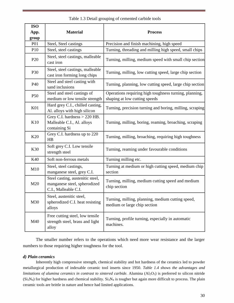
Table 1.3 Detail grouping of cemented carbide tools
ISO
App.
group
Material
Process
P01 Steel, Steel castings Precision and finish machining, high speed
P10 Steel, steel castings Turning, threading and milling high speed, small chips
P20 Steel, steel castings, malleable
cast iron Turning, milling, medium speed with small chip section
P30 Steel, steel castings, malleable
cast iron forming long chips Turning, milling, low cutting speed, large chip section
P40 Steel and steel casting with
sand inclusions Turning, planning, low cutting speed, large chip section
P50 Steel and steel castings of
medium or low tensile strength
Operations requiring high toughness turning, planning,
shaping at low cutting speeds
K01 Hard grey C.I., chilled casting,
Al. alloys with high silicon Turning, precision turning and boring, milling, scraping
K10
Grey C.I. hardness > 220 HB.
Malleable C.I., Al. alloys
containing Si
Turning, milling, boring, reaming, broaching, scraping
K20 Grey C.I. hardness up to 220
HB Turning, milling, broaching, requiring high toughness
K30 Soft grey C.I. Low tensile
strength steel Turning, reaming under favourable conditions
K40 Soft non-ferrous metals Turning milling etc.
M10 Steel, steel castings,
manganese steel, grey C.I.
Turning at medium or high cutting speed, medium chip
section
M20
Steel casting, austenitic steel,
manganese steel, spherodized
C.I., Malleable C.I.
Turning, milling, medium cutting speed and medium
chip section
M30
Steel, austenitic steel,
spherodized C.I. heat resisting
alloys
Turning, milling, planning, medium cutting speed,
medium or large chip section
M40
Free cutting steel, low tensile
strength steel, brass and light
alloy
Turning, profile turning, especially in automatic
machines.
The smaller number refers to the operations which need more wear resistance and the larger
numbers to those requiring higher toughness for the tool.
d) Plain ceramics
Inherently high compressive strength, chemical stability and hot hardness of the ceramics led to powder
metallurgical production of indexable ceramic tool inserts since 1950. Table 1.4 shows the advantages and
limitations of alumina ceramics in contrast to sintered carbide. Alumina (Al2O3) is preferred to silicon nitride
(Si3N4) for higher hardness and chemical stability. Si3N4 is tougher but again more difficult to process. The plain
ceramic tools are brittle in nature and hence had limited applications.
UNIT - I MACHINE TOOLS
31 DEPT. OF MECH. ENGG.
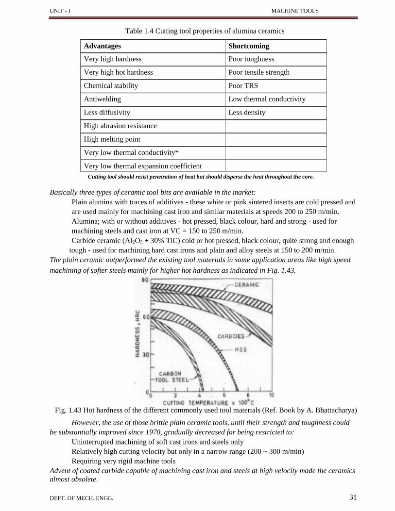
Table 1.4 Cutting tool properties of alumina ceramics
Advantages Shortcoming
Very high hardness Poor toughness
Very high hot hardness Poor tensile strength
Chemical stability Poor TRS
Antiwelding Low thermal conductivity
Less diffusivity Less density
High abrasion resistance
High melting point
Very low thermal conductivity*
Very low thermal expansion coefficient
Cutting tool should resist penetration of heat but should disperse the heat throughout the core.
Basically three types of ceramic tool bits are available in the market:
Plain alumina with traces of additives - these white or pink sintered inserts are cold pressed and
are used mainly for machining cast iron and similar materials at speeds 200 to 250 m/min.
Alumina; with or without additives - hot pressed, black colour, hard and strong - used for
machining steels and cast iron at VC = 150 to 250 m/min.
Carbide ceramic (Al2O3 + 30% TiC) cold or hot pressed, black colour, quite strong and enough
tough - used for machining hard cast irons and plain and alloy steels at 150 to 200 m/min.
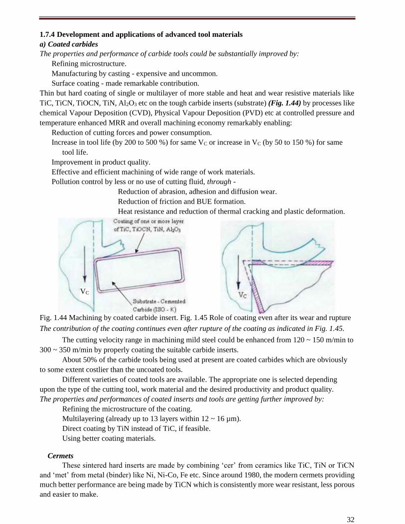
The plain ceramic outperformed the existing tool materials in some application areas like high speed
machining of softer steels mainly for higher hot hardness as indicated in Fig. 1.43.
Fig. 1.43 Hot hardness of the different commonly used tool materials (Ref. Book by A. Bhattacharya)
However, the use of those brittle plain ceramic tools, until their strength and toughness could
be substantially improved since 1970, gradually decreased for being restricted to:
Uninterrupted machining of soft cast irons and steels only
Relatively high cutting velocity but only in a narrow range (200 ~ 300 m/min)
Requiring very rigid machine tools
Advent of coated carbide capable of machining cast iron and steels at high velocity made the ceramics
almost obsolete.
32
1.7.4 Development and applications of advanced tool materials
a) Coated carbides
The properties and performance of carbide tools could be substantially improved by:
Refining microstructure.
Manufacturing by casting - expensive and uncommon.
Surface coating - made remarkable contribution.
Thin but hard coating of single or multilayer of more stable and heat and wear resistive materials like
TiC, TiCN, TiOCN, TiN, Al2O3 etc on the tough carbide inserts (substrate) (Fig. 1.44) by processes like
chemical Vapour Deposition (CVD), Physical Vapour Deposition (PVD) etc at controlled pressure and
temperature enhanced MRR and overall machining economy remarkably enabling:
Reduction of cutting forces and power consumption.
Increase in tool life (by 200 to 500 %) for same VC or increase in VC (by 50 to 150 %) for same
tool life.
Improvement in product quality.
Effective and efficient machining of wide range of work materials.
Pollution control by less or no use of cutting fluid, through -
Reduction of abrasion, adhesion and diffusion wear.
Reduction of friction and BUE formation.
Heat resistance and reduction of thermal cracking and plastic deformation.
Fig. 1.44 Machining by coated carbide insert. Fig. 1.45 Role of coating even after its wear and rupture
The contribution of the coating continues even after rupture of the coating as indicated in Fig. 1.45.
The cutting velocity range in machining mild steel could be enhanced from 120 ~ 150 m/min to
300 ~ 350 m/min by properly coating the suitable carbide inserts.
About 50% of the carbide tools being used at present are coated carbides which are obviously
to some extent costlier than the uncoated tools.
Different varieties of coated tools are available. The appropriate one is selected depending
upon the type of the cutting tool, work material and the desired productivity and product quality.
The properties and performances of coated inserts and tools are getting further improved by:
Refining the microstructure of the coating.
Multilayering (already up to 13 layers within 12 ~ 16 µm).
Direct coating by TiN instead of TiC, if feasible.
Using better coating materials.
Cermets
These sintered hard inserts are made by combining ‘cer’ from ceramics like TiC, TiN or TiCN
and ‘met’ from metal (binder) like Ni, Ni-Co, Fe etc. Since around 1980, the modern cermets providing
much better performance are being made by TiCN which is consistently more wear resistant, less porous
and easier to make.
VC
33
UNIT - I MACHINE TOOLS
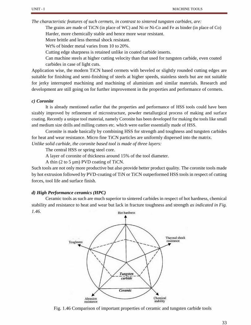
The characteristic features of such cermets, in contrast to sintered tungsten carbides, are:
The grains are made of TiCN (in place of WC) and Ni or Ni-Co and Fe as binder (in place of Co)
Harder, more chemically stable and hence more wear resistant.
More brittle and less thermal shock resistant.
Wt% of binder metal varies from 10 to 20%.
Cutting edge sharpness is retained unlike in coated carbide inserts.
Can machine steels at higher cutting velocity than that used for tungsten carbide, even coated
carbides in case of light cuts.
Application wise, the modern TiCN based cermets with beveled or slightly rounded cutting edges are
suitable for finishing and semi-finishing of steels at higher speeds, stainless steels but are not suitable
for jerky interrupted machining and machining of aluminium and similar materials. Research and
development are still going on for further improvement in the properties and performance of cermets.
c) Coronite
It is already mentioned earlier that the properties and performance of HSS tools could have been
sizably improved by refinement of microstructure, powder metallurgical process of making and surface
coating. Recently a unique tool material, namely Coronite has been developed for making the tools like small
and medium size drills and milling cutters etc. which were earlier essentially made of HSS.
Coronite is made basically by combining HSS for strength and toughness and tungsten carbides
for heat and wear resistance. Micro fine TiCN particles are uniformly dispersed into the matrix.
Unlike solid carbide, the coronite based tool is made of three layers:
The central HSS or spring steel core.
A layer of coronite of thickness around 15% of the tool diameter.
A thin (2 to 5 µm) PVD coating of TiCN.
Such tools are not only more productive but also provide better product quality. The coronite tools made
by hot extrusion followed by PVD-coating of TiN or TiCN outperformed HSS tools in respect of cutting
forces, tool life and surface finish.
d) High Performance ceramics (HPC)
Ceramic tools as such are much superior to sintered carbides in respect of hot hardness, chemical
stability and resistance to heat and wear but lack in fracture toughness and strength as indicated in Fig.
1.46.
Fig. 1.46 Comparison of important properties of ceramic and tungsten carbide tools
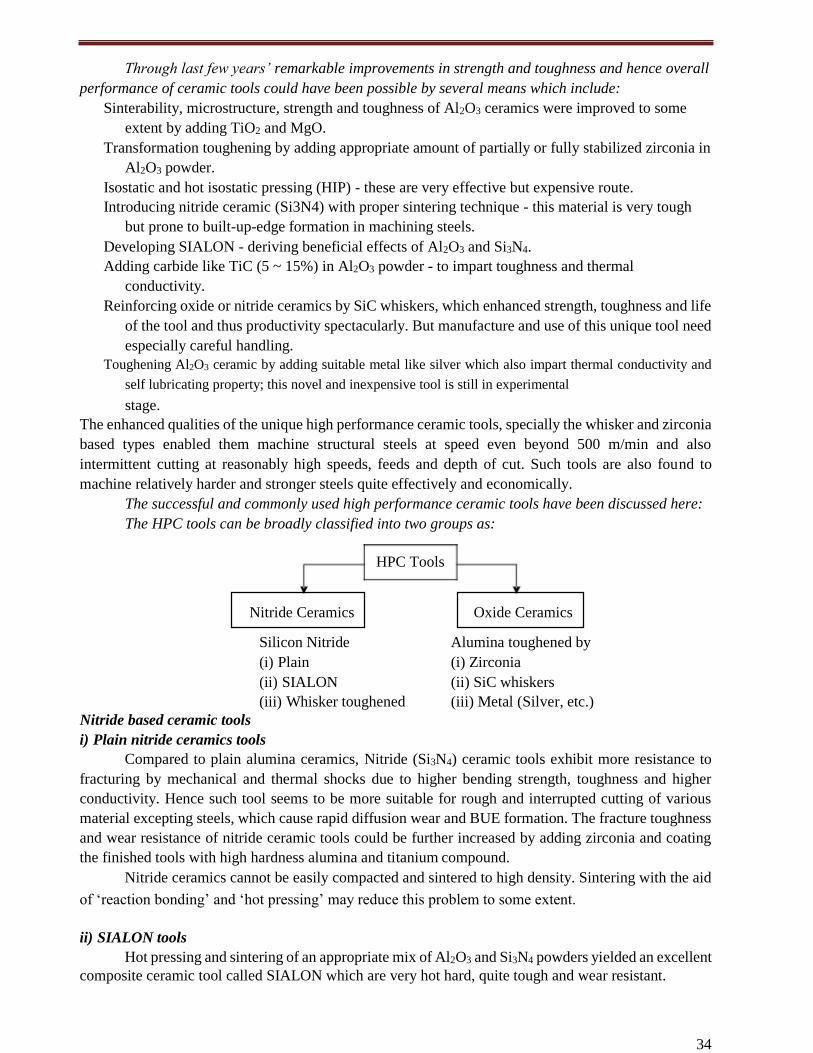
34
Through last few years’ remarkable improvements in strength and toughness and hence overall
performance of ceramic tools could have been possible by several means which include:
Sinterability, microstructure, strength and toughness of Al2O3 ceramics were improved to some
extent by adding TiO2 and MgO.
Transformation toughening by adding appropriate amount of partially or fully stabilized zirconia in
Al2O3 powder.
Isostatic and hot isostatic pressing (HIP) - these are very effective but expensive route.
Introducing nitride ceramic (Si3N4) with proper sintering technique - this material is very tough
but prone to built-up-edge formation in machining steels.
Developing SIALON - deriving beneficial effects of Al2O3 and Si3N4.
Adding carbide like TiC (5 ~ 15%) in Al2O3 powder - to impart toughness and thermal
conductivity.
Reinforcing oxide or nitride ceramics by SiC whiskers, which enhanced strength, toughness and life
of the tool and thus productivity spectacularly. But manufacture and use of this unique tool need
especially careful handling.
Toughening Al2O3 ceramic by adding suitable metal like silver which also impart thermal conductivity and
self lubricating property; this novel and inexpensive tool is still in experimental
stage.
The enhanced qualities of the unique high performance ceramic tools, specially the whisker and zirconia
based types enabled them machine structural steels at speed even beyond 500 m/min and also
intermittent cutting at reasonably high speeds, feeds and depth of cut. Such tools are also found to
machine relatively harder and stronger steels quite effectively and economically.
The successful and commonly used high performance ceramic tools have been discussed here:
The HPC tools can be broadly classified into two groups as:
Silicon Nitride Alumina toughened by
(i) Plain (i) Zirconia
(ii) SIALON (ii) SiC whiskers
(iii) Whisker toughened (iii) Metal (Silver, etc.)
Nitride based ceramic tools
i) Plain nitride ceramics tools
Compared to plain alumina ceramics, Nitride (Si3N4) ceramic tools exhibit more resistance to
fracturing by mechanical and thermal shocks due to higher bending strength, toughness and higher
conductivity. Hence such tool seems to be more suitable for rough and interrupted cutting of various
material excepting steels, which cause rapid diffusion wear and BUE formation. The fracture toughness
and wear resistance of nitride ceramic tools could be further increased by adding zirconia and coating
the finished tools with high hardness alumina and titanium compound.
Nitride ceramics cannot be easily compacted and sintered to high density. Sintering with the aid
of ‘reaction bonding’ and ‘hot pressing’ may reduce this problem to some extent.
ii) SIALON tools
Hot pressing and sintering of an appropriate mix of Al2O3 and Si3N4 powders yielded an excellent
composite ceramic tool called SIALON which are very hot hard, quite tough and wear resistant.
HPC Tools
Oxide Ceramics Nitride Ceramics
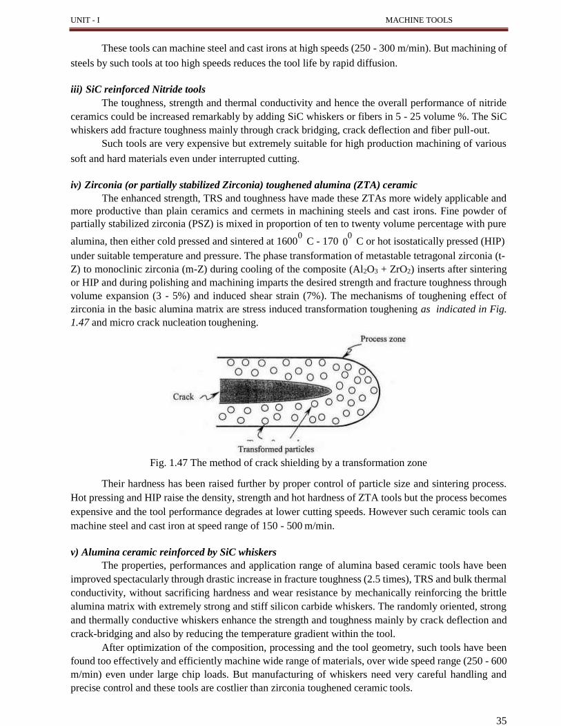
35
UNIT - I MACHINE TOOLS
0
These tools can machine steel and cast irons at high speeds (250 - 300 m/min). But machining of
steels by such tools at too high speeds reduces the tool life by rapid diffusion.
iii) SiC reinforced Nitride tools
The toughness, strength and thermal conductivity and hence the overall performance of nitride
ceramics could be increased remarkably by adding SiC whiskers or fibers in 5 - 25 volume %. The SiC
whiskers add fracture toughness mainly through crack bridging, crack deflection and fiber pull-out.
Such tools are very expensive but extremely suitable for high production machining of various
soft and hard materials even under interrupted cutting.
iv) Zirconia (or partially stabilized Zirconia) toughened alumina (ZTA) ceramic
The enhanced strength, TRS and toughness have made these ZTAs more widely applicable and
more productive than plain ceramics and cermets in machining steels and cast irons. Fine powder of
partially stabilized zirconia (PSZ) is mixed in proportion of ten to twenty volume percentage with pure
alumina, then either cold pressed and sintered at 16000
C - 170 0
C or hot isostatically pressed (HIP)
under suitable temperature and pressure. The phase transformation of metastable tetragonal zirconia (t-
Z) to monoclinic zirconia (m-Z) during cooling of the composite (Al2O3 + ZrO2) inserts after sintering
or HIP and during polishing and machining imparts the desired strength and fracture toughness through
volume expansion (3 - 5%) and induced shear strain (7%). The mechanisms of toughening effect of
zirconia in the basic alumina matrix are stress induced transformation toughening as indicated in Fig.
1.47 and micro crack nucleation toughening.
Fig. 1.47 The method of crack shielding by a transformation zone
Their hardness has been raised further by proper control of particle size and sintering process.
Hot pressing and HIP raise the density, strength and hot hardness of ZTA tools but the process becomes
expensive and the tool performance degrades at lower cutting speeds. However such ceramic tools can
machine steel and cast iron at speed range of 150 - 500 m/min.
v) Alumina ceramic reinforced by SiC whiskers
The properties, performances and application range of alumina based ceramic tools have been
improved spectacularly through drastic increase in fracture toughness (2.5 times), TRS and bulk thermal
conductivity, without sacrificing hardness and wear resistance by mechanically reinforcing the brittle
alumina matrix with extremely strong and stiff silicon carbide whiskers. The randomly oriented, strong
and thermally conductive whiskers enhance the strength and toughness mainly by crack deflection and
crack-bridging and also by reducing the temperature gradient within the tool.
After optimization of the composition, processing and the tool geometry, such tools have been
found too effectively and efficiently machine wide range of materials, over wide speed range (250 - 600
m/min) even under large chip loads. But manufacturing of whiskers need very careful handling and
precise control and these tools are costlier than zirconia toughened ceramic tools.
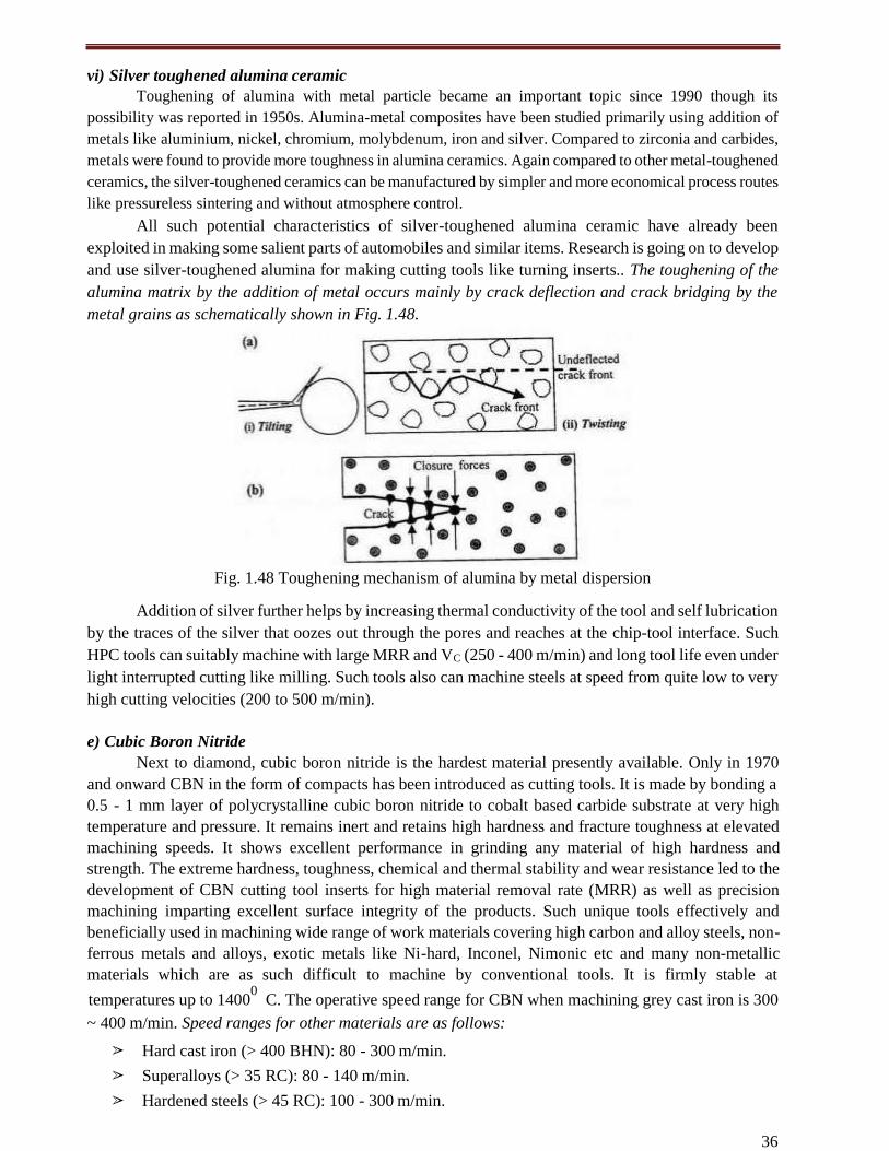
36
vi) Silver toughened alumina ceramic
Toughening of alumina with metal particle became an important topic since 1990 though its
possibility was reported in 1950s. Alumina-metal composites have been studied primarily using addition of
metals like aluminium, nickel, chromium, molybdenum, iron and silver. Compared to zirconia and carbides,
metals were found to provide more toughness in alumina ceramics. Again compared to other metal-toughened
ceramics, the silver-toughened ceramics can be manufactured by simpler and more economical process routes
like pressureless sintering and without atmosphere control.
All such potential characteristics of silver-toughened alumina ceramic have already been
exploited in making some salient parts of automobiles and similar items. Research is going on to develop
and use silver-toughened alumina for making cutting tools like turning inserts.. The toughening of the
alumina matrix by the addition of metal occurs mainly by crack deflection and crack bridging by the
metal grains as schematically shown in Fig. 1.48.
Fig. 1.48 Toughening mechanism of alumina by metal dispersion
Addition of silver further helps by increasing thermal conductivity of the tool and self lubrication
by the traces of the silver that oozes out through the pores and reaches at the chip-tool interface. Such
HPC tools can suitably machine with large MRR and VC (250 - 400 m/min) and long tool life even under
light interrupted cutting like milling. Such tools also can machine steels at speed from quite low to very
high cutting velocities (200 to 500 m/min).
e) Cubic Boron Nitride
Next to diamond, cubic boron nitride is the hardest material presently available. Only in 1970
and onward CBN in the form of compacts has been introduced as cutting tools. It is made by bonding a
0.5 - 1 mm layer of polycrystalline cubic boron nitride to cobalt based carbide substrate at very high
temperature and pressure. It remains inert and retains high hardness and fracture toughness at elevated
machining speeds. It shows excellent performance in grinding any material of high hardness and
strength. The extreme hardness, toughness, chemical and thermal stability and wear resistance led to the
development of CBN cutting tool inserts for high material removal rate (MRR) as well as precision
machining imparting excellent surface integrity of the products. Such unique tools effectively and
beneficially used in machining wide range of work materials covering high carbon and alloy steels, non-
ferrous metals and alloys, exotic metals like Ni-hard, Inconel, Nimonic etc and many non-metallic
materials which are as such difficult to machine by conventional tools. It is firmly stable at
temperatures up to 14000
C. The operative speed range for CBN when machining grey cast iron is 300
~ 400 m/min. Speed ranges for other materials are as follows:
➢ Hard cast iron (> 400 BHN): 80 - 300 m/min.
➢ Superalloys (> 35 RC): 80 - 140 m/min.
➢ Hardened steels (> 45 RC): 100 - 300 m/min.
37
UNIT - I MACHINE TOOLS
In addition to speed, the most important factor that affects performance of CBN inserts is the
preparation of cutting edge. It is best to use CBN tools with a honed or chamfered edge preparation,
especially for interrupted cuts. Like ceramics, CBN tools are also available only in the form of indexable
inserts. The only limitation of it is its high cost.
(f) Diamond Tools
Single stone, natural or synthetic, diamond crystals are used as tips/edge of cutting tools. Owing
to the extreme hardness and sharp edges, natural single crystal is used for many applications, particularly
where high accuracy and precision are required. Their important uses are:
Single point cutting tool tips and small drills for high speed machining of non-ferrous metals,
ceramics, plastics, composites, etc. and effective machining of difficult-to-machine materials.
Drill bits for mining, oil exploration, etc.
Tool for cutting and drilling in glasses, stones, ceramics, FRPs etc.
Wire drawing and extrusion dies.
Superabrasive wheels for critical grinding.
Limited supply, increasing demand, high cost and easy cleavage of natural diamond demanded a more
reliable source of diamond. It led to the invention and manufacture of artificial diamond grits by ultra-high
temperature and pressure synthesis process, which enables large scale manufacture of diamond with some
control over size, shape and friability of the diamond grits as desired for various applications.
i) Polycrystalline Diamond (PCD)
The polycrystalline diamond (PCD) tools consist of a layer (0.5 to 1.5 mm) of fine grain size,
randomly oriented diamond particles sintered with a suitable binder (usually cobalt) and then
metallurgically bonded to a suitable substrate like cemented carbide or Si3N4 inserts. PCD exhibits
excellent wear resistance, hold sharp edge, generates little friction in the cut, provide high fracture
strength, and had good thermal conductivity. These properties contribute to PCD tooling’s long life in
conventional and high speed machining of soft, non-ferrous materials (aluminium, magnesium, copper
etc), advanced composites and metal-matrix composites, superalloys, and non-metallic materials.
PCD is particularly well suited for abrasive materials (i.e. drilling and reaming metal matrix
composites) where it provides 100 times the life of carbides. PCD is not usually recommended for
ferrous metals because of high solubility of diamond (carbon) in these materials at elevated temperature.
However, they can be used to machine some of these materials under special conditions; for example,
light cuts are being successfully made in grey cast iron. The main advantage of such PCD tool is the
greater toughness due to finer microstructure with random orientation of the grains and reduced
cleavage.
But such unique PCD also suffers from some limitations like:
High tool cost.
Presence of binder, cobalt, which reduces wear resistance and thermal stability.
Complex tool shapes like in-built chip breaker cannot be made.
Size restriction, particularly in making very small diameter tools.
The above mentioned limitations of polycrystalline diamond tools have been almost overcome by
developing Diamond coated tools.
ii) Diamond coated carbide tools
Since the invention of low pressure synthesis of diamond from gaseous phase, continuous effort
has been made to use thin film diamond in cutting tool field. These are normally used as thin (<50 µm)
or thick (> 200 µm) films of diamond synthesized by CVD method for cutting tools, dies, wear surfaces
and even abrasives for Abrasive Jet Machining (AJM) and grinding.
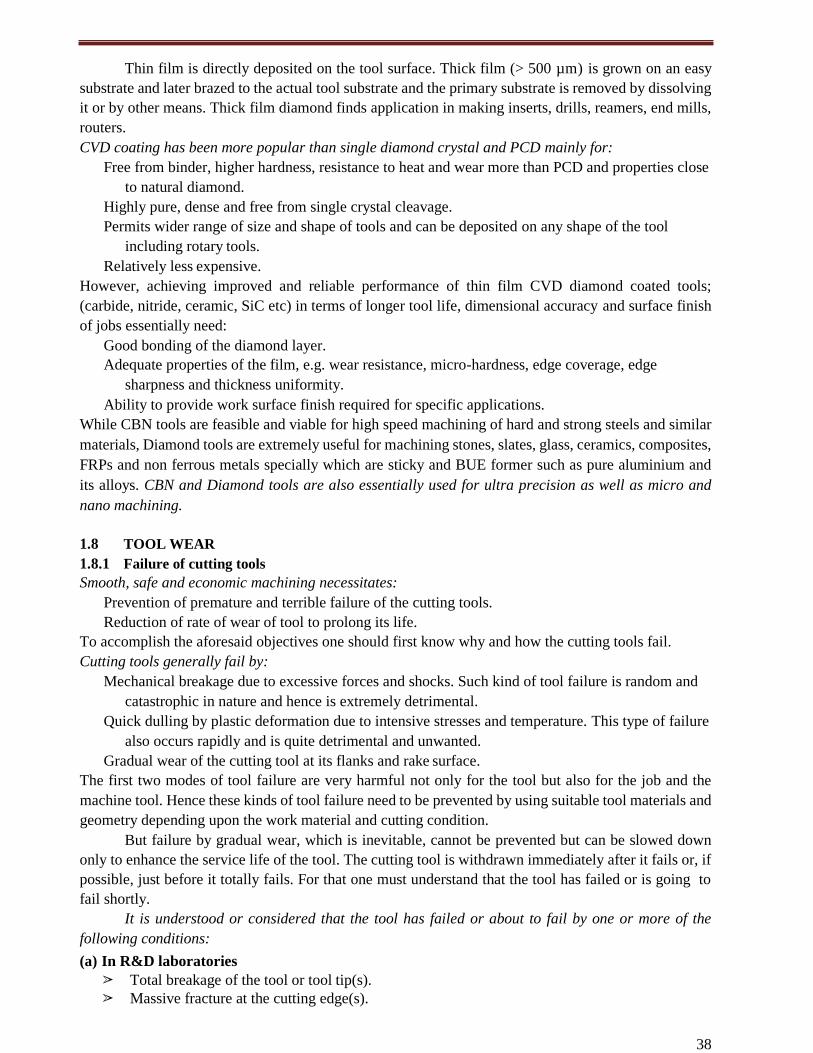
38
Thin film is directly deposited on the tool surface. Thick film (> 500 µm) is grown on an easy
substrate and later brazed to the actual tool substrate and the primary substrate is removed by dissolving
it or by other means. Thick film diamond finds application in making inserts, drills, reamers, end mills,
routers.
CVD coating has been more popular than single diamond crystal and PCD mainly for:
Free from binder, higher hardness, resistance to heat and wear more than PCD and properties close
to natural diamond.
Highly pure, dense and free from single crystal cleavage.
Permits wider range of size and shape of tools and can be deposited on any shape of the tool
including rotary tools.
Relatively less expensive.
However, achieving improved and reliable performance of thin film CVD diamond coated tools;
(carbide, nitride, ceramic, SiC etc) in terms of longer tool life, dimensional accuracy and surface finish
of jobs essentially need:
Good bonding of the diamond layer.
Adequate properties of the film, e.g. wear resistance, micro-hardness, edge coverage, edge
sharpness and thickness uniformity.
Ability to provide work surface finish required for specific applications.
While CBN tools are feasible and viable for high speed machining of hard and strong steels and similar
materials, Diamond tools are extremely useful for machining stones, slates, glass, ceramics, composites,
FRPs and non ferrous metals specially which are sticky and BUE former such as pure aluminium and
its alloys. CBN and Diamond tools are also essentially used for ultra precision as well as micro and
nano machining.
1.8 TOOL WEAR
1.8.1 Failure of cutting tools
Smooth, safe and economic machining necessitates:
Prevention of premature and terrible failure of the cutting tools.
Reduction of rate of wear of tool to prolong its life.
To accomplish the aforesaid objectives one should first know why and how the cutting tools fail.
Cutting tools generally fail by:
Mechanical breakage due to excessive forces and shocks. Such kind of tool failure is random and
catastrophic in nature and hence is extremely detrimental.
Quick dulling by plastic deformation due to intensive stresses and temperature. This type of failure
also occurs rapidly and is quite detrimental and unwanted.
Gradual wear of the cutting tool at its flanks and rake surface.
The first two modes of tool failure are very harmful not only for the tool but also for the job and the
machine tool. Hence these kinds of tool failure need to be prevented by using suitable tool materials and
geometry depending upon the work material and cutting condition.
But failure by gradual wear, which is inevitable, cannot be prevented but can be slowed down
only to enhance the service life of the tool. The cutting tool is withdrawn immediately after it fails or, if
possible, just before it totally fails. For that one must understand that the tool has failed or is going to
fail shortly.
It is understood or considered that the tool has failed or about to fail by one or more of the
following conditions:
(a) In R&D laboratories
➢ Total breakage of the tool or tool tip(s).
➢ Massive fracture at the cutting edge(s).
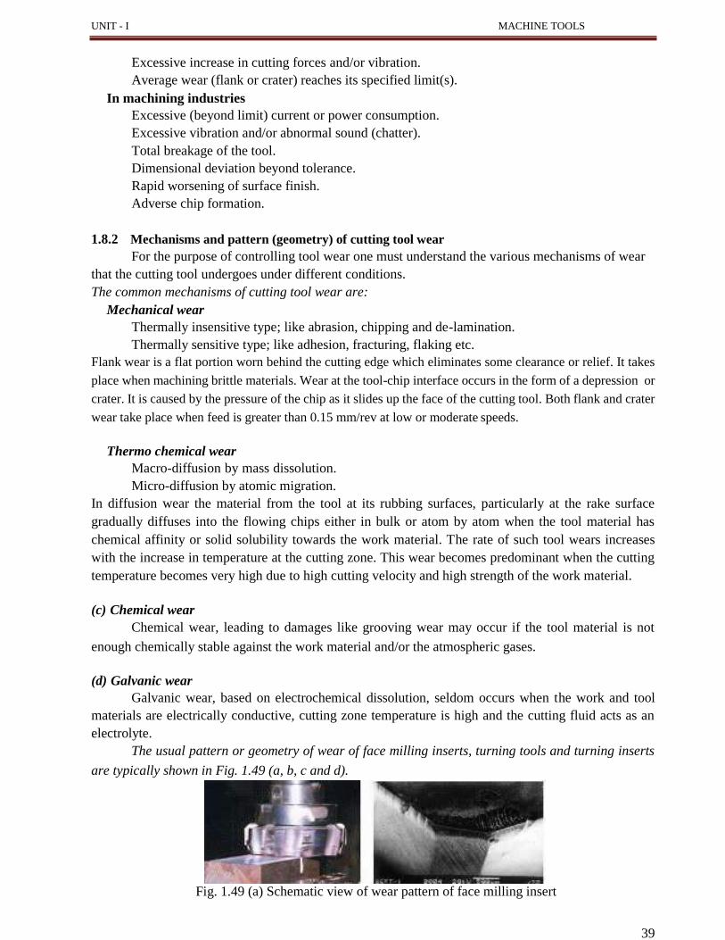
39
UNIT - I MACHINE TOOLS
Excessive increase in cutting forces and/or vibration.
Average wear (flank or crater) reaches its specified limit(s).
In machining industries
Excessive (beyond limit) current or power consumption.
Excessive vibration and/or abnormal sound (chatter).
Total breakage of the tool.
Dimensional deviation beyond tolerance.
Rapid worsening of surface finish.
Adverse chip formation.
1.8.2 Mechanisms and pattern (geometry) of cutting tool wear
For the purpose of controlling tool wear one must understand the various mechanisms of wear
that the cutting tool undergoes under different conditions.
The common mechanisms of cutting tool wear are:
Mechanical wear
Thermally insensitive type; like abrasion, chipping and de-lamination.
Thermally sensitive type; like adhesion, fracturing, flaking etc.
Flank wear is a flat portion worn behind the cutting edge which eliminates some clearance or relief. It takes
place when machining brittle materials. Wear at the tool-chip interface occurs in the form of a depression or
crater. It is caused by the pressure of the chip as it slides up the face of the cutting tool. Both flank and crater
wear take place when feed is greater than 0.15 mm/rev at low or moderate speeds.
Thermo chemical wear
Macro-diffusion by mass dissolution.
Micro-diffusion by atomic migration.
In diffusion wear the material from the tool at its rubbing surfaces, particularly at the rake surface
gradually diffuses into the flowing chips either in bulk or atom by atom when the tool material has
chemical affinity or solid solubility towards the work material. The rate of such tool wears increases
with the increase in temperature at the cutting zone. This wear becomes predominant when the cutting
temperature becomes very high due to high cutting velocity and high strength of the work material.
(c) Chemical wear
Chemical wear, leading to damages like grooving wear may occur if the tool material is not
enough chemically stable against the work material and/or the atmospheric gases.
(d) Galvanic wear
Galvanic wear, based on electrochemical dissolution, seldom occurs when the work and tool
materials are electrically conductive, cutting zone temperature is high and the cutting fluid acts as an
electrolyte.
The usual pattern or geometry of wear of face milling inserts, turning tools and turning inserts
are typically shown in Fig. 1.49 (a, b, c and d).
Fig. 1.49 (a) Schematic view of wear pattern of face milling insert
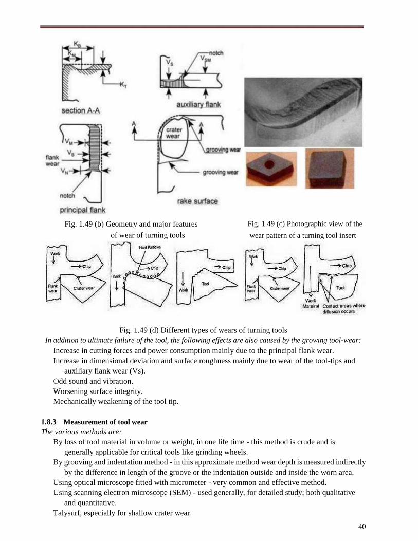
Fig. 1.49 (b) Geometry and major features
of wear of turning tools
Fig. 1.49 (c) Photographic view of the
wear pattern of a turning tool insert
Fig. 1.49 (d) Different types of wears of turning tools
In addition to ultimate failure of the tool, the following effects are also caused by the growing tool-wear:
Increase in cutting forces and power consumption mainly due to the principal flank wear.
Increase in dimensional deviation and surface roughness mainly due to wear of the tool-tips and
auxiliary flank wear (Vs).
Odd sound and vibration.
Worsening surface integrity.
Mechanically weakening of the tool tip.
1.8.3 Measurement of tool wear
The various methods are:
By loss of tool material in volume or weight, in one life time - this method is crude and is
generally applicable for critical tools like grinding wheels.
By grooving and indentation method - in this approximate method wear depth is measured indirectly
by the difference in length of the groove or the indentation outside and inside the worn area.
Using optical microscope fitted with micrometer - very common and effective method.
Using scanning electron microscope (SEM) - used generally, for detailed study; both qualitative
and quantitative.
Talysurf, especially for shallow crater wear.
40


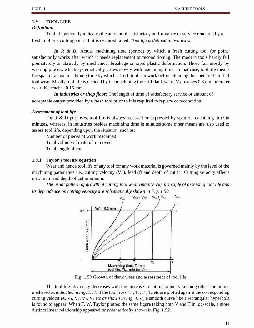
41
UNIT - I MACHINE TOOLS
1.9 TOOL LIFE
Definition:
Tool life generally indicates the amount of satisfactory performance or service rendered by a
fresh tool or a cutting point till it is declared failed. Tool life is defined in two ways:
In R & D: Actual machining time (period) by which a fresh cutting tool (or point)
satisfactorily works after which it needs replacement or reconditioning. The modern tools hardly fail
prematurely or abruptly by mechanical breakage or rapid plastic deformation. Those fail mostly by
wearing process which systematically grows slowly with machining time. In that case, tool life means
the span of actual machining time by which a fresh tool can work before attaining the specified limit of
tool wear. Mostly tool life is decided by the machining time till flank wear, VB reaches 0.3 mm or crater
wear, KT reaches 0.15 mm.
In industries or shop floor: The length of time of satisfactory service or amount of
acceptable output provided by a fresh tool prior to it is required to replace or recondition.
Assessment of tool life
For R & D purposes, tool life is always assessed or expressed by span of machining time in
minutes, whereas, in industries besides machining time in minutes some other means are also used to
assess tool life, depending upon the situation, such as:
Number of pieces of work machined.
Total volume of material removed.
Total length of cut.
1.9.1 Taylor’s tool life equation
Wear and hence tool life of any tool for any work material is governed mainly by the level of the
machining parameters i.e., cutting velocity (VC), feed (f) and depth of cut (t). Cutting velocity affects
maximum and depth of cut minimum.
The usual pattern of growth of cutting tool wear (mainly VB), principle of assessing tool life and
its dependence on cutting velocity are schematically shown in Fig. 1.50.
Fig. 1.50 Growth of flank wear and assessment of tool life
The tool life obviously decreases with the increase in cutting velocity keeping other conditions
unaltered as indicated in Fig. 1.51. If the tool lives, T1, T2, T3, T4 etc are plotted against the corresponding
cutting velocities, V1, V2, V3, V4 etc as shown in Fig. 1.51, a smooth curve like a rectangular hyperbola
is found to appear. When F. W. Taylor plotted the same figure taking both V and T in log-scale, a more
distinct linear relationship appeared as schematically shown in Fig. 1.52.
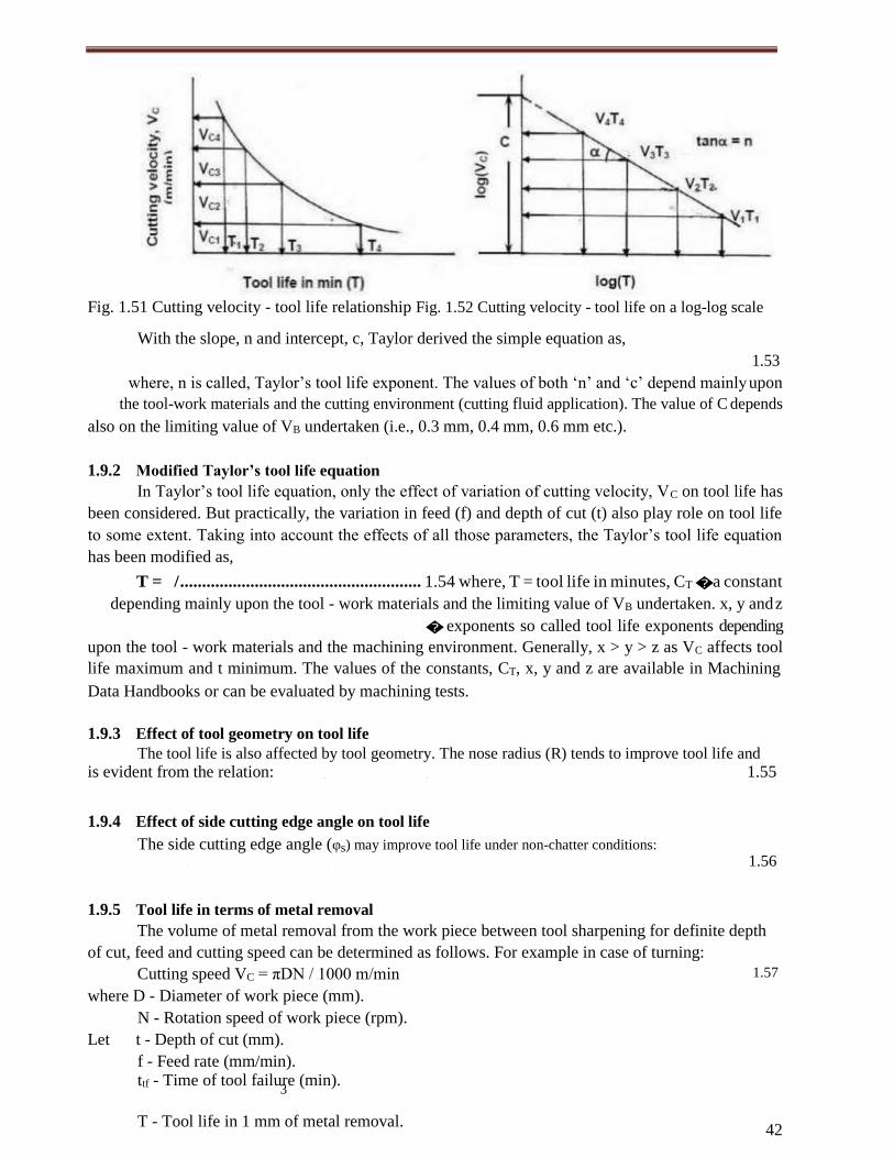
42
Fig. 1.51 Cutting velocity - tool life relationship Fig. 1.52 Cutting velocity - tool life on a log-log scale
With the slope, n and intercept, c, Taylor derived the simple equation as,
1.53
where, n is called, Taylor’s tool life exponent. The values of both ‘n’ and ‘c’ depend mainly upon
the tool-work materials and the cutting environment (cutting fluid application). The value of C depends
also on the limiting value of VB undertaken (i.e., 0.3 mm, 0.4 mm, 0.6 mm etc.).
1.9.2 Modified Taylor’s tool life equation
In Taylor’s tool life equation, only the effect of variation of cutting velocity, VC on tool life has
been considered. But practically, the variation in feed (f) and depth of cut (t) also play role on tool life
to some extent. Taking into account the effects of all those parameters, the Taylor’s tool life equation
has been modified as,
T = / ....................................................... 1.54 where, T = tool life in minutes, CT � a constant
depending mainly upon the tool - work materials and the limiting value of VB undertaken. x, y and z
� exponents so called tool life exponents depending
upon the tool - work materials and the machining environment. Generally, x > y > z as VC affects tool
life maximum and t minimum. The values of the constants, CT, x, y and z are available in Machining
Data Handbooks or can be evaluated by machining tests.
1.9.3 Effect of tool geometry on tool life
The tool life is also affected by tool geometry. The nose radius (R) tends to improve tool life and
is evident from the relation: . . 1.55
1.9.4 Effect of side cutting edge angle on tool life
The side cutting edge angle (φs) may improve tool life under non-chatter conditions:
. . 1.56
1.9.5 Tool life in terms of metal removal
The volume of metal removal from the work piece between tool sharpening for definite depth
of cut, feed and cutting speed can be determined as follows. For example in case of turning:
Cutting speed VC = πDN / 1000 m/min
where D - Diameter of work piece (mm).
N - Rotation speed of work piece (rpm).
Let t - Depth of cut (mm).
f - Feed rate (mm/min). ttf - Time of tool failure (min).
3
1.57
T - Tool life in 1 mm of metal removal.
43
UNIT - I MACHINE TOOLS
Volume of metal removed per revolution = π.D.t.f mm3
1.58
Volume of metal removed per minute = π.D.t.f.N mm3
1.59
Volume of metal removed in ‘ttf’ minute = π.D.t.f.N.ttf mm3
1.60
Therefore, Volume of metal removed between tool grinds = π.D.t.f.N.ttf mm3
1.61
T = π.D.t.f.N.ttf mm3
= 1000.VC.t.f.ttf mm3
1.62
T = VC.t.f.ttf cm3
1.63
1.9.6 Factors affecting tool life
The life of the cutting tool is affected by the following factors:
Cutting speed.
Feed and depth of cut.
Tool geometry.
Tool material.
Cutting fluid.
Work piece material.
Rigidity of work, tool and machine.
1.9.7 Machinability
1.9.7.1 Concept, definition and criteria of judgement of machinability
The term; ‘Machinability’ has been introduced for gradation of work materials with respect to
machining characteristics. But truly speaking, there is no unique or clear meaning of the term
machinability. People tried to describe “Machinability” in several ways such as:
It is generally applied to the machining properties of work material.
It refers to material (work) response to machining.
It is the ability of the work material to be machined.
It indicates how easily and fast a material can be machined.
But it has been agreed, in general, that it is difficult to clearly define and quantify Machinability. For
instance, saying ‘material A is more machinable than material B’ may mean that compared to ‘B’:
‘A’ causes lesser tool wear or longer tool life.
‘A’ requires lesser cutting forces and power.
‘A’ provides better surface finish.
Attempts were made to measure or quantify machinability and it was done mostly in terms of:
Tool life which substantially influences productivity and economy in machining.
Magnitude of cutting forces which affects power consumption and dimensional accuracy.
Surface finish which plays role on performance and service life of the product.
Often cutting temperature and chip form are also considered for assessing machinability.
Machinability rating (MR) = x 100 1.64
The free cutting steel, AISI - 1112, when machined (turned) at 100 fpm, provided 60 min of tool
life. If the work material to be tested provides 60 min of tool life at cutting velocity of 60 fpm (say), as
indicated in Fig. 1.53, under the same set of machining condition, then machinability (rating) of that
material would be,
MR = 100 60 % or simply 60 (based on 100% for the standard material) or, simply the
value of the cutting velocity expressed in fpm at which a work material provides 60 min tool life was
directly considered as the MR of that work material. In this way the MR of some materials, for instance,
were evaluated as,
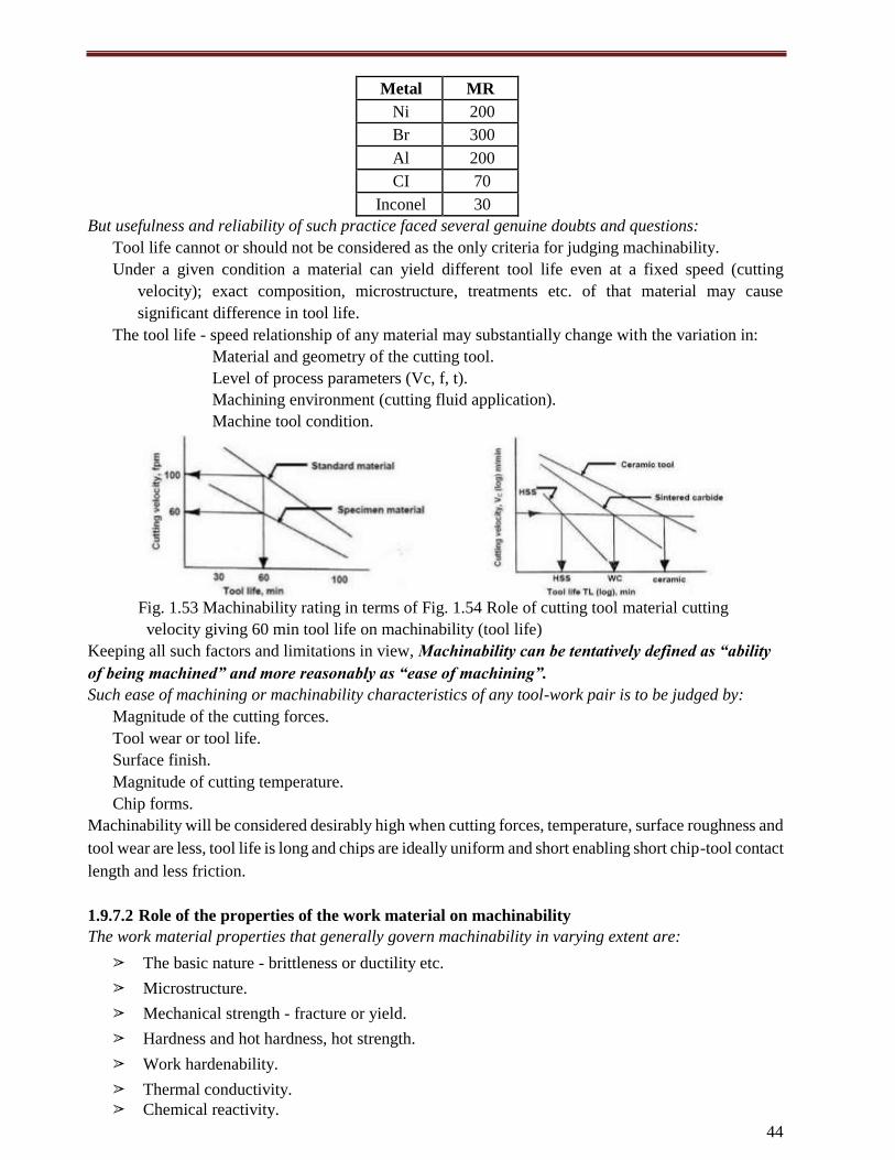
44
Metal MR
Ni 200
Br 300
Al 200
CI 70
Inconel 30
But usefulness and reliability of such practice faced several genuine doubts and questions:
Tool life cannot or should not be considered as the only criteria for judging machinability.
Under a given condition a material can yield different tool life even at a fixed speed (cutting
velocity); exact composition, microstructure, treatments etc. of that material may cause
significant difference in tool life.
The tool life - speed relationship of any material may substantially change with the variation in:
Material and geometry of the cutting tool.
Level of process parameters (Vc, f, t).
Machining environment (cutting fluid application).
Machine tool condition.
Fig. 1.53 Machinability rating in terms of Fig. 1.54 Role of cutting tool material cutting
velocity giving 60 min tool life on machinability (tool life)
Keeping all such factors and limitations in view, Machinability can be tentatively defined as “ability
of being machined” and more reasonably as “ease of machining”.
Such ease of machining or machinability characteristics of any tool-work pair is to be judged by:
Magnitude of the cutting forces.
Tool wear or tool life.
Surface finish.
Magnitude of cutting temperature.
Chip forms.
Machinability will be considered desirably high when cutting forces, temperature, surface roughness and
tool wear are less, tool life is long and chips are ideally uniform and short enabling short chip-tool contact
length and less friction.
1.9.7.2 Role of the properties of the work material on machinability
The work material properties that generally govern machinability in varying extent are:
➢ The basic nature - brittleness or ductility etc.
➢ Microstructure.
➢ Mechanical strength - fracture or yield.
➢ Hardness and hot hardness, hot strength.
➢ Work hardenability.
➢ Thermal conductivity.
➢ Chemical reactivity.

45
➢ Stickiness / self lubricity.

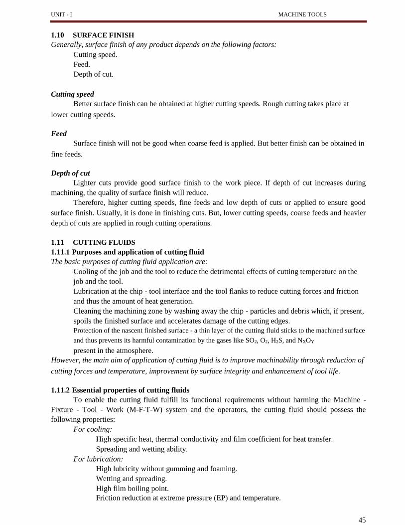
UNIT - I MACHINE TOOLS
1.10 SURFACE FINISH
Generally, surface finish of any product depends on the following factors:
Cutting speed.
Feed.
Depth of cut.
Cutting speed
Better surface finish can be obtained at higher cutting speeds. Rough cutting takes place at
lower cutting speeds.
Feed
Surface finish will not be good when coarse feed is applied. But better finish can be obtained in
fine feeds.
Depth of cut
Lighter cuts provide good surface finish to the work piece. If depth of cut increases during
machining, the quality of surface finish will reduce.
Therefore, higher cutting speeds, fine feeds and low depth of cuts or applied to ensure good
surface finish. Usually, it is done in finishing cuts. But, lower cutting speeds, coarse feeds and heavier
depth of cuts are applied in rough cutting operations.
1.11 CUTTING FLUIDS
1.11.1 Purposes and application of cutting fluid
The basic purposes of cutting fluid application are:
Cooling of the job and the tool to reduce the detrimental effects of cutting temperature on the
job and the tool.
Lubrication at the chip - tool interface and the tool flanks to reduce cutting forces and friction
and thus the amount of heat generation.
Cleaning the machining zone by washing away the chip - particles and debris which, if present,
spoils the finished surface and accelerates damage of the cutting edges.
Protection of the nascent finished surface - a thin layer of the cutting fluid sticks to the machined surface
and thus prevents its harmful contamination by the gases like SO2, O2, H2S, and NXOY
present in the atmosphere.
However, the main aim of application of cutting fluid is to improve machinability through reduction of
cutting forces and temperature, improvement by surface integrity and enhancement of tool life.
1.11.2 Essential properties of cutting fluids
To enable the cutting fluid fulfill its functional requirements without harming the Machine -
Fixture - Tool - Work (M-F-T-W) system and the operators, the cutting fluid should possess the
following properties:
For cooling:
High specific heat, thermal conductivity and film coefficient for heat transfer.
Spreading and wetting ability.
For lubrication:
High lubricity without gumming and foaming.
Wetting and spreading.
High film boiling point.
Friction reduction at extreme pressure (EP) and temperature.
45
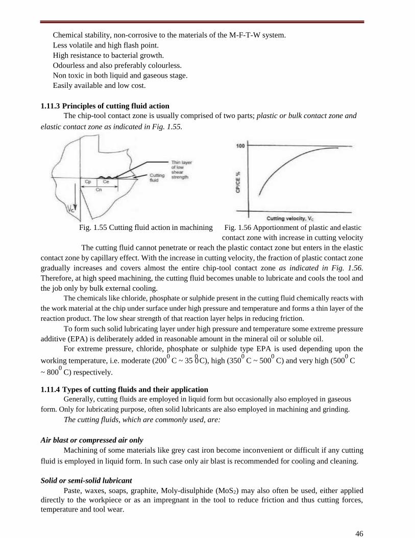
46
0
Chemical stability, non-corrosive to the materials of the M-F-T-W system.
Less volatile and high flash point.
High resistance to bacterial growth.
Odourless and also preferably colourless.
Non toxic in both liquid and gaseous stage.
Easily available and low cost.
1.11.3 Principles of cutting fluid action
The chip-tool contact zone is usually comprised of two parts; plastic or bulk contact zone and
elastic contact zone as indicated in Fig. 1.55.
Fig. 1.55 Cutting fluid action in machining Fig. 1.56 Apportionment of plastic and elastic
contact zone with increase in cutting velocity
The cutting fluid cannot penetrate or reach the plastic contact zone but enters in the elastic
contact zone by capillary effect. With the increase in cutting velocity, the fraction of plastic contact zone
gradually increases and covers almost the entire chip-tool contact zone as indicated in Fig. 1.56.
Therefore, at high speed machining, the cutting fluid becomes unable to lubricate and cools the tool and
the job only by bulk external cooling.
The chemicals like chloride, phosphate or sulphide present in the cutting fluid chemically reacts with
the work material at the chip under surface under high pressure and temperature and forms a thin layer of the
reaction product. The low shear strength of that reaction layer helps in reducing friction.
To form such solid lubricating layer under high pressure and temperature some extreme pressure
additive (EPA) is deliberately added in reasonable amount in the mineral oil or soluble oil.
For extreme pressure, chloride, phosphate or sulphide type EPA is used depending upon the
working temperature, i.e. moderate (2000
C ~ 35 0
C), high (3500
C ~ 5000
C) and very high (5000
C
~ 8000
C) respectively.
1.11.4 Types of cutting fluids and their application
Generally, cutting fluids are employed in liquid form but occasionally also employed in gaseous
form. Only for lubricating purpose, often solid lubricants are also employed in machining and grinding.
The cutting fluids, which are commonly used, are:
Air blast or compressed air only
Machining of some materials like grey cast iron become inconvenient or difficult if any cutting
fluid is employed in liquid form. In such case only air blast is recommended for cooling and cleaning.
Solid or semi-solid lubricant
Paste, waxes, soaps, graphite, Moly-disulphide (MoS2) may also often be used, either applied
directly to the workpiece or as an impregnant in the tool to reduce friction and thus cutting forces,
temperature and tool wear.
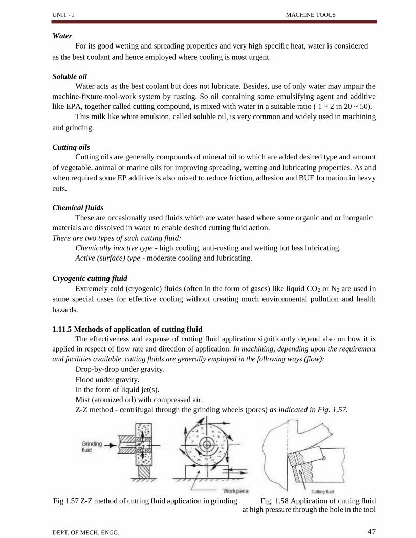
UNIT - I MACHINE TOOLS
Water
For its good wetting and spreading properties and very high specific heat, water is considered
as the best coolant and hence employed where cooling is most urgent.
Soluble oil
Water acts as the best coolant but does not lubricate. Besides, use of only water may impair the
machine-fixture-tool-work system by rusting. So oil containing some emulsifying agent and additive
like EPA, together called cutting compound, is mixed with water in a suitable ratio ( 1 ~ 2 in 20 ~ 50).
This milk like white emulsion, called soluble oil, is very common and widely used in machining
and grinding.
Cutting oils
Cutting oils are generally compounds of mineral oil to which are added desired type and amount
of vegetable, animal or marine oils for improving spreading, wetting and lubricating properties. As and
when required some EP additive is also mixed to reduce friction, adhesion and BUE formation in heavy
cuts.
Chemical fluids
These are occasionally used fluids which are water based where some organic and or inorganic
materials are dissolved in water to enable desired cutting fluid action.
There are two types of such cutting fluid:
Chemically inactive type - high cooling, anti-rusting and wetting but less lubricating.
Active (surface) type - moderate cooling and lubricating.
Cryogenic cutting fluid
Extremely cold (cryogenic) fluids (often in the form of gases) like liquid CO2 or N2 are used in
some special cases for effective cooling without creating much environmental pollution and health
hazards.
1.11.5 Methods of application of cutting fluid
The effectiveness and expense of cutting fluid application significantly depend also on how it is
applied in respect of flow rate and direction of application. In machining, depending upon the requirement
and facilities available, cutting fluids are generally employed in the following ways (flow):
Drop-by-drop under gravity.
Flood under gravity.
In the form of liquid jet(s).
Mist (atomized oil) with compressed air.
Z-Z method - centrifugal through the grinding wheels (pores) as indicated in Fig. 1.57.
Fig 1.57 Z-Z method of cutting fluid application in grinding Fig. 1.58 Application of cutting fluid at high pressure through the hole in the tool
DEPT. OF MECH. ENGG. 47
48
The direction of application also significantly governs the effectiveness of the cutting fluid in
respect of reaching at or near the chip-tool and work-tool interfaces. Depending upon the requirement
and accessibility the cutting fluid is applied from top or side(s). In operations like deep hole drilling the
pressurized fluid is often sent through the axial or inner spiral hole(s) of the drill.
For effective cooling and lubrication in high speed machining of ductile metals having wide and
plastic chip-tool contact, cutting fluid may be pushed at high pressure to the chip-tool interface through
hole(s) in the cutting tool, as schematically shown in Fig. 1.58.
1.11.6 Selection of cutting fluid
The benefits of application of cutting fluid largely depend upon proper selection of the type of
the cutting fluid depending upon the work material, tool material and the machining condition. As for
example, for high speed machining of not-difficult-to-machine materials greater cooling type fluids are
preferred and for low speed machining of both conventional and difficult-to-machine materials greater
lubricating type fluid is preferred.
Selection of cutting fluids for machining some common engineering materials and operations are
presented as follows:
Grey cast iron:
Generally dry for its self lubricating property.
Air blast for cooling and flushing chips.
Soluble oil for cooling and flushing chips in high speed machining and grinding.
Steels:
If machined by HSS tools, sol. Oil (1: 20 ~30) for low carbon and alloy steels and neat oil with
EPA for heavy cuts.
If machined by carbide tools thinner sol. Oil for low strength steel, thicker sol. Oil ( 1:10 ~ 20) for
stronger steels and straight sulphurised oil for heavy and low speed cuts and EP cutting oil for
high alloy steel.
Often steels are machined dry by carbide tools for preventing thermal shocks.
Aluminium and its alloys:
Preferably machined dry.
Light but oily soluble oil.
Straight neat oil or kerosene oil for stringent cuts.
Copper and its alloys:
Water based fluids are generally used.
Oil with or without inactive EPA for tougher grades of Cu-alloy.
Stainless steels and Heat resistant alloys:
High performance soluble oil or neat oil with high concentration with chlorinated EP additive. The
brittle ceramics and cermets should be used either under dry condition or light neat oil in
case of fine finishing.
Grinding at high speed needs cooling (1: 50 ~ 100) soluble oil. For finish grinding of metals
and alloys low viscosity neat oil is also used.
UNIT - II CENTRE LATHE AND SPECIAL PURPOSE LATHES
49
UNIT - II
CENTRE LATHE AND SPECIAL PURPOSE LATHES
2.1 CENTRE LATHE
Lathe is the oldest machine tool invented, starting with the Egyptian tree lathes. It is the father
of all machine tools. Its main function is to remove material from a work piece to produce the required
shape and size. This is accomplished by holding the work piece securely and rigidly on the machine and
then turning it against the cutting tool which will remove material from the work piece in the form of
chips. It is used to machine cylindrical parts. Generally single point cutting tool is used. In the year 1797
Henry Maudslay, an Englishman, designed the first screw cutting lathe which is the forerunner of the
present day high speed, heavy duty production lathe.
2.1.1 Classification of lathes
Lathes are very versatile of wide use and are classified according to several aspects:
According to configuration:
➢ Horizontal - Most common for ergonomic conveniences.
➢ Vertical - Occupies less floor space, only some large lathes are of this type.
According to purpose of use:
➢ General purpose - Very versatile where almost all possible types of operations are carried
out on wide ranges of size, shape and materials of jobs; e.g.: centre lathes.
➢ Single purpose - Only one (occasionally two) type of operation is done on limited ranges
of size and material of jobs; e.g.: facing lathe, roll turning lathe etc.
➢ Special purpose - Where a definite number and type of operations are done repeatedly over
long time on a specific type of blank; e.g.: capstan lathe, turret lathe, gear blanking lathe etc.
According to size or capacity:
➢ Small (low duty) - In such light duty lathes (up to 1.1 kW), only small and medium
size jobs of generally soft and easily machinable materials are machined.
➢ Medium (medium duty) - These lathes of power nearly up to 11 kW are most versatile and
commonly used.
➢ Large (heavy duty)
➢ Mini or micro lathe - These are tiny table-top lathes used for extremely small size jobs
and precision work; e.g.: Swiss type automatic lathe.
According to configuration of the jobs being handled:
➢ Bar type - Slender rod like jobs being held in collets.
➢ Chucking type - Disc type jobs being held in chucks.
➢ Housing type - Odd shape jobs, being held in face plate.
According to precision:
Ordinary
Precision (lathes) - These sophisticated lathes meant for high accuracy and finish and are
relatively more expensive.
According to number of spindles:
➢ Single spindle - Common.
➢ Multi-spindle (2, 4, 6 or 8 spindles) - Such uncommon lathes are suitably used for fast and mass
production of small size and simple shaped jobs.
According to type of automation:
➢ Fixed automation - Conventional; e.g.: single spindle automat & Swiss type automatic lathe

50
➢ Flexible automation - Modern; e.g.: CNC lathe, turning centre etc.

UNIT - II
50
According to degree of automation:
Non-automatic - Almost all the handling operations are done manually; e.g.: centre lathes.
Semi-automatic - Nearly half of the handling operations, irrespective of the processing
operations, are done automatically and rest manually; e.g.: copying lathe, relieving lathe etc.
➢ Automatic - Almost all the handling operations (and obviously all the processing operations)
are done automatically; e.g.: single spindle automat, Swiss type automatic lathe, etc.
2.2 CONSTRUCTIONAL FEATURES
2.2.1 Major parts of a centre lathe
Amongst the various types of lathes, centre lathes are the most versatile and commonly used.
Fig. 2.1 shows the basic configuration of a center lathe. The major parts are:
Fig. 2.1 Schematic view of a center lathe
Headstock It holds the spindle and through that power and rotation are transmitted to the job at different
speeds. Various work holding attachments such as three jaw chucks, collets, and centres can be held in
the spindle. The spindle is driven by an electric motor through a system of belt drives and gear trains.
Spindle rotational speed is controlled by varying the geometry of the drive train.
Tailstock The tailstock can be used to support the end of the work piece with a center, to support longer
blanks or to hold tools for drilling, reaming, threading, or cutting tapers. It can be adjusted in position
along the ways to accommodate different length work pieces. The tailstock barrel can be fed along the
axis of rotation with the tailstock hand wheel.
Bed Headstock is fixed and tailstock is clamped on it. Tailstock has a provision to slide and facilitate
operations at different locations. The bed is fixed on columns and the carriage travels on it.
Carriage It is supported on the lathe bed-ways and can move in a direction parallel to the lathe axis. The
carriage is used for giving various movements to the tool by hand and by power. It carries saddle, cross-
slide, compound rest, tool post and apron.
Saddle It carries the cross slide, compound rest and tool post. It is an
H-shaped casting fitted over the bed. It moves alone to guide ways.
Cross-slide It carries the compound rest and tool post. It is mounted on the top
of the saddle. It can be moved by hand or may be given power feed through apron mechanism.
UNIT - II
51
Compound rest It is mounted on the cross slide. It carries a circular base called swivel
plate which is graduated in degrees. It is used during taper turning to set the tool for angular cuts. The
upper part known as compound slide can be moved by means of a hand wheel.
Tool post It is fitted over the compound rest. The tool is clamped in it.
Apron Lower part of the carriage is termed as the apron. It is attached to
the saddle and hangs in front of the bed. It contains gears, clutches and levers for moving the carriage
by a hand wheel or power feed.
Feed mechanism The movement of the tool relative to the work piece is termed as “feed”. The lathe
tool can be given three types of feed, namely, longitudinal, cross and angular.
When the tool moves parallel to the axis of the lathe, the movement is called longitudinal feed.
This is achieved by moving the carriage.
When the tool moves perpendicular to the axis of the lathe, the movement is called cross feed.
This is achieved by moving the cross slide.
When the tool moves at an angle to the axis of the lathe, the movement is called angular feed.
This is achieved by moving the compound slide, after swiveling it at an angle to the lathe axis.
Feed rod The feed rod is a long shaft, used to move the carriage or cross-slide for turning, facing, boring
and all other operations except thread cutting. Power is transmitted from the lathe spindle to the apron
gears through the feed rod via a large number of gears.
Lead screw The lead screw is long threaded shaft used as a master screw and brought into operation
only when threads have to cut. In all other times the lead screw is disengaged from the gear box and
remains stationary. The rotation of the lead screw is used to traverse the tool along the work to produce
screw. The half nut makes the carriage to engage or disengage the lead screw.
2.2.2 Kinematic system and working principle of a centre lathe
Fig. 2.2 schematically shows the kinematic system of a 12 speed centre lathe.
Fig. 2.2 Kinematic system of a 12 speed centre lathe
For machining in machine tools the job and the cutting tool need to be moved relative to each
other. The tool-work motions are:
Formative motions: - cutting motion, feed motion.
Auxiliary motions: - indexing motion, relieving motion.
UNIT - II
52
In lathes: Cutting motion is attained by rotating the job and feed motion is attained by linear
travel of the tool either axially for longitudinal feed or radially for cross feed.
It is noted, in general, from Fig. 2.2. The job gets rotation (and power) from the motor through the belt-
pulley, clutch and then the speed gear box which splits the input speed into a number (here 12) of speeds
by operating the cluster gears.
The cutting tool derives its automatic feed motion(s) from the rotation of the spindle via the gear
quadrant, feed gear box and then the apron mechanism where the rotation of the feed rod is transmitted:
Either to the pinion which being rolled along the rack provides the longitudinal feed.
Or to the screw of the cross slide for cross or transverse feed.
While cutting screw threads the half nuts are engaged with the rotating lead screw to positively
cause travel of the carriage and hence the tool parallel to the lathe bed i.e., job axis.
The feed-rate for both turning and threading is varied as needed by operating the Norton gear
and the Meander drive systems existing in the feed gear box (FGB). The range of feeds can be augmented
by changing the gear ratio in the gear quadrant connecting the FGB with the spindle.
As and when required, the tailstock is shifted along the lathe bed by operating the clamping bolt
and the tailstock quill is moved forward or backward or is kept locked in the desired location. The
versatility or working range of the centre lathes is augmented by using several special attachments.
2.2.3 Headstock driving mechanisms
There are two types of headstock driving mechanisms as follows:
Back geared headstock.
All geared headstock.
2.2.3.1 Back geared headstock
Back gear arrangement is used for reducing the spindle speed, which is necessary for thread
cutting and knurling. The back gear arrangement is shown in Fig.2.3.
Fig. 2.3 Back gear arrangement
There is one stepped cone pulley in the lathe spindle. This pulley can freely rotate on the spindle.
A pinion gear P1 is connected to small end of the cone pulley. P1 will rotate when cone pulley rotates.
Bull gear G1 is keyed to lathe spindle such that the spindle will rotate when Gear G1 rotates. Speed
changes can be obtained by changing the flat belt on the steps. A bull gear G1 may be locked or unlocked
with this cone pulley by a lock pin.
There are two back gears B1 and B2 on a back shaft. It is operated by means of hand lever L; back
gears B1 and B2 can be engaged or disengaged with G1 and P1. For getting direct speed, back gear is not
engaged. The step cone pulley is locked with the main spindle by using the lock pin. The flat belt is
changed for different steps. Thus three or four ranges of speed can be obtained directly.
53
UNIT - II
For getting slow or indirect speeds, back gear is engaged by lever L and lock pin is disengaged.
Now, power will flow from P1 to B1. B1 to B2 (same shaft), B2 to G1 to spindle. As gear B1 is larger than
P1, the speed will further be reduced at B1. B1 and B2 will have the same speeds. The speed will further
be reduced at G1 because gear G1 is larger than B2. So, the speed of spindle is reduced by engaging the
back gear.
2.2.3.2 All geared headstock
All geared headstock is commonly used in modern lathes because of the following advantages:
It gives wider range of spindle speeds.
It is more efficient and compact than cone pulley mechanism.
Power available at the tool is almost constant for all spindle speeds.
Belt shifting is eliminated.
The vibration of the spindle is reduced.
More power can be transmitted.
The all geared headstock is shown in Fig 2.4.
Fig. 2.4 All geared headstock
The power from the constant speed motor is delivered to the spindle through a belt drive. Speed
changing is made by levers. The different spindle speeds are obtained by shifting the levers into different
positions to obtain different gear combinations. This mechanism has a splined spindle, intermediate shaft and
a splined shaft. The splined shaft receives power from motor through a belt drive.
This shaft has 3 gears namely G1, G2 and G3. These gears can be shifted with the help of lever
along the shaft. Gears G4, G5 and G6 are mounted on intermediate shaft and cannot be moved axially.
Gears G7, G8 and G9 are mounted on splined headstock spindle and can be moved axially be levers.
Gears G1, G2 and G3 can be meshed with the gears G4, G5 and G6 individually. Similarly, gears G7, G8,
G9 can be meshed with gear G4, G5 and G6 individually. Thus, it provides nine different speeds.
2.2.4 Feed mechanisms
The feed mechanism is used to transmit power from the spindle to the carriage. Therefore, it
converts rotary motion of the spindle into linear motion of the carriage. The feed can be given either by
hand or automatically. For automatic feeding, the following feed mechanisms are used:
Tumbler gear reversing mechanism.
Quick-change gearbox.
Tumbler gear quick-change gearbox.
Apron mechanism.
Bevel gear feed reversing mechanism.
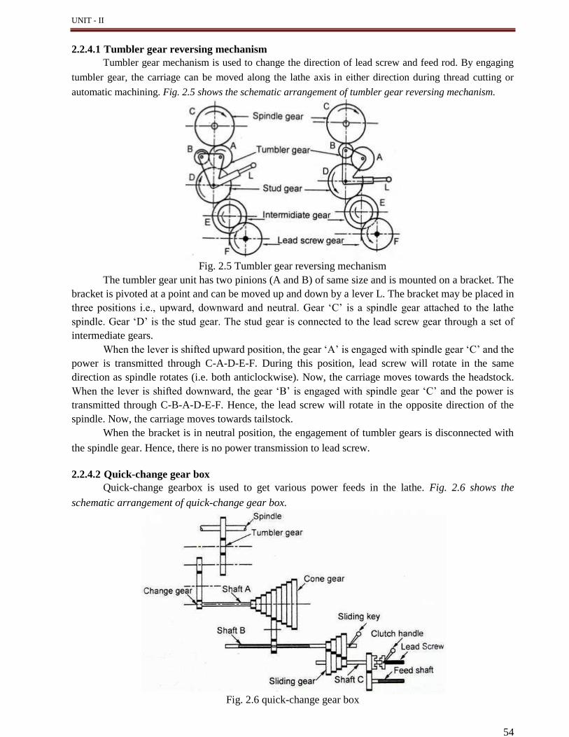
54
UNIT - II
2.2.4.1 Tumbler gear reversing mechanism
Tumbler gear mechanism is used to change the direction of lead screw and feed rod. By engaging
tumbler gear, the carriage can be moved along the lathe axis in either direction during thread cutting or
automatic machining. Fig. 2.5 shows the schematic arrangement of tumbler gear reversing mechanism.
Fig. 2.5 Tumbler gear reversing mechanism
The tumbler gear unit has two pinions (A and B) of same size and is mounted on a bracket. The
bracket is pivoted at a point and can be moved up and down by a lever L. The bracket may be placed in
three positions i.e., upward, downward and neutral. Gear ‘C’ is a spindle gear attached to the lathe
spindle. Gear ‘D’ is the stud gear. The stud gear is connected to the lead screw gear through a set of
intermediate gears.
When the lever is shifted upward position, the gear ‘A’ is engaged with spindle gear ‘C’ and the
power is transmitted through C-A-D-E-F. During this position, lead screw will rotate in the same
direction as spindle rotates (i.e. both anticlockwise). Now, the carriage moves towards the headstock.
When the lever is shifted downward, the gear ‘B’ is engaged with spindle gear ‘C’ and the power is
transmitted through C-B-A-D-E-F. Hence, the lead screw will rotate in the opposite direction of the
spindle. Now, the carriage moves towards tailstock.
When the bracket is in neutral position, the engagement of tumbler gears is disconnected with
the spindle gear. Hence, there is no power transmission to lead screw.
2.2.4.2 Quick-change gear box
Quick-change gearbox is used to get various power feeds in the lathe. Fig. 2.6 shows the
schematic arrangement of quick-change gear box.
Fig. 2.6 quick-change gear box
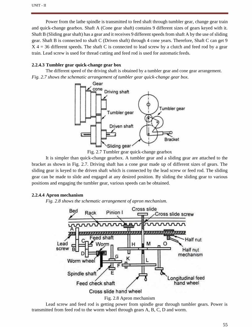
55
UNIT - II
Power from the lathe spindle is transmitted to feed shaft through tumbler gear, change gear train
and quick-change gearbox. Shaft A (Cone gear shaft) contains 9 different sizes of gears keyed with it.
Shaft B (Sliding gear shaft) has a gear and it receives 9 different speeds from shaft A by the use of sliding
gear. Shaft B is connected to shaft C (Driven shaft) through 4 cone years. Therefore, Shaft C can get 9
X 4 = 36 different speeds. The shaft C is connected to lead screw by a clutch and feed rod by a gear
train. Lead screw is used for thread cutting and feed rod is used for automatic feeds.
2.2.4.3 Tumbler gear quick-change gear box
The different speed of the driving shaft is obtained by a tumbler gear and cone gear arrangement.
Fig. 2.7 shows the schematic arrangement of tumbler gear quick-change gear box.
Fig. 2.7 Tumbler gear quick-change gearbox
It is simpler than quick-change gearbox. A tumbler gear and a sliding gear are attached to the
bracket as shown in Fig. 2.7. Driving shaft has a cone gear made up of different sizes of gears. The
sliding gear is keyed to the driven shaft which is connected by the lead screw or feed rod. The sliding
gear can be made to slide and engaged at any desired position. By sliding the sliding gear to various
positions and engaging the tumbler gear, various speeds can be obtained.
2.2.4.4 Apron mechanism
Fig. 2.8 shows the schematic arrangement of apron mechanism.
Fig. 2.8 Apron mechanism
Lead screw and feed rod is getting power from spindle gear through tumbler gears. Power is
transmitted from feed rod to the worm wheel through gears A, B, C, D and worm.
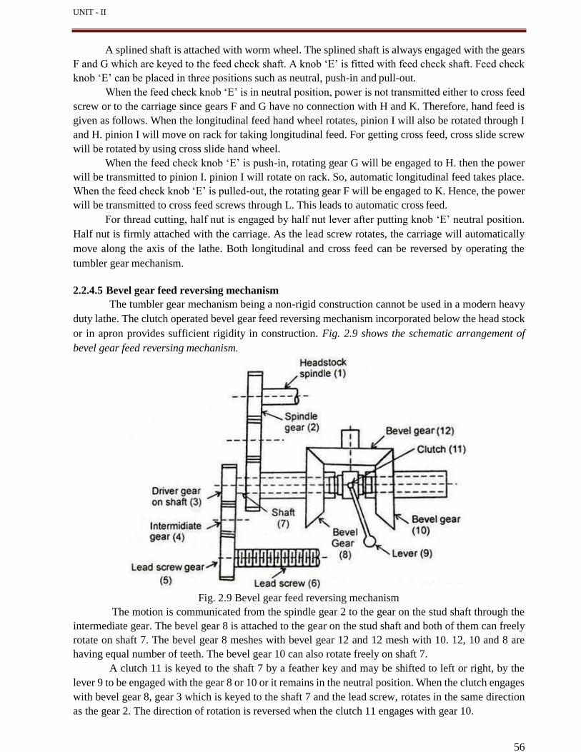
56
UNIT - II
A splined shaft is attached with worm wheel. The splined shaft is always engaged with the gears
F and G which are keyed to the feed check shaft. A knob ‘E’ is fitted with feed check shaft. Feed check
knob ‘E’ can be placed in three positions such as neutral, push-in and pull-out.
When the feed check knob ‘E’ is in neutral position, power is not transmitted either to cross feed
screw or to the carriage since gears F and G have no connection with H and K. Therefore, hand feed is
given as follows. When the longitudinal feed hand wheel rotates, pinion I will also be rotated through I
and H. pinion I will move on rack for taking longitudinal feed. For getting cross feed, cross slide screw
will be rotated by using cross slide hand wheel.
When the feed check knob ‘E’ is push-in, rotating gear G will be engaged to H. then the power
will be transmitted to pinion I. pinion I will rotate on rack. So, automatic longitudinal feed takes place.
When the feed check knob ‘E’ is pulled-out, the rotating gear F will be engaged to K. Hence, the power
will be transmitted to cross feed screws through L. This leads to automatic cross feed.
For thread cutting, half nut is engaged by half nut lever after putting knob ‘E’ neutral position.
Half nut is firmly attached with the carriage. As the lead screw rotates, the carriage will automatically
move along the axis of the lathe. Both longitudinal and cross feed can be reversed by operating the
tumbler gear mechanism.
2.2.4.5 Bevel gear feed reversing mechanism
The tumbler gear mechanism being a non-rigid construction cannot be used in a modern heavy
duty lathe. The clutch operated bevel gear feed reversing mechanism incorporated below the head stock
or in apron provides sufficient rigidity in construction. Fig. 2.9 shows the schematic arrangement of
bevel gear feed reversing mechanism.
Fig. 2.9 Bevel gear feed reversing mechanism
The motion is communicated from the spindle gear 2 to the gear on the stud shaft through the
intermediate gear. The bevel gear 8 is attached to the gear on the stud shaft and both of them can freely
rotate on shaft 7. The bevel gear 8 meshes with bevel gear 12 and 12 mesh with 10. 12, 10 and 8 are
having equal number of teeth. The bevel gear 10 can also rotate freely on shaft 7.
A clutch 11 is keyed to the shaft 7 by a feather key and may be shifted to left or right, by the
lever 9 to be engaged with the gear 8 or 10 or it remains in the neutral position. When the clutch engages
with bevel gear 8, gear 3 which is keyed to the shaft 7 and the lead screw, rotates in the same direction
as the gear 2. The direction of rotation is reversed when the clutch 11 engages with gear 10.
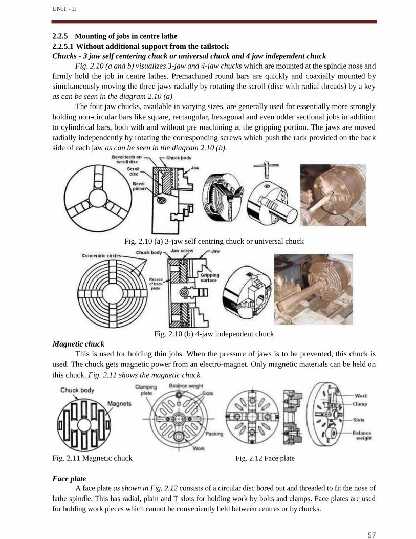
57
UNIT - II
2.2.5 Mounting of jobs in centre lathe
2.2.5.1 Without additional support from the tailstock
Chucks - 3 jaw self centering chuck or universal chuck and 4 jaw independent chuck
Fig. 2.10 (a and b) visualizes 3-jaw and 4-jaw chucks which are mounted at the spindle nose and
firmly hold the job in centre lathes. Premachined round bars are quickly and coaxially mounted by
simultaneously moving the three jaws radially by rotating the scroll (disc with radial threads) by a key
as can be seen in the diagram 2.10 (a)
The four jaw chucks, available in varying sizes, are generally used for essentially more strongly
holding non-circular bars like square, rectangular, hexagonal and even odder sectional jobs in addition
to cylindrical bars, both with and without pre machining at the gripping portion. The jaws are moved
radially independently by rotating the corresponding screws which push the rack provided on the back
side of each jaw as can be seen in the diagram 2.10 (b).
Fig. 2.10 (a) 3-jaw self centring chuck or universal chuck
Fig. 2.10 (b) 4-jaw independent chuck
Magnetic chuck
This is used for holding thin jobs. When the pressure of jaws is to be prevented, this chuck is
used. The chuck gets magnetic power from an electro-magnet. Only magnetic materials can be held on
this chuck. Fig. 2.11 shows the magnetic chuck.
Fig. 2.11 Magnetic chuck Fig. 2.12 Face plate
Face plate
A face plate as shown in Fig. 2.12 consists of a circular disc bored out and threaded to fit the nose of
lathe spindle. This has radial, plain and T slots for holding work by bolts and clamps. Face plates are used
for holding work pieces which cannot be conveniently held between centres or by chucks.
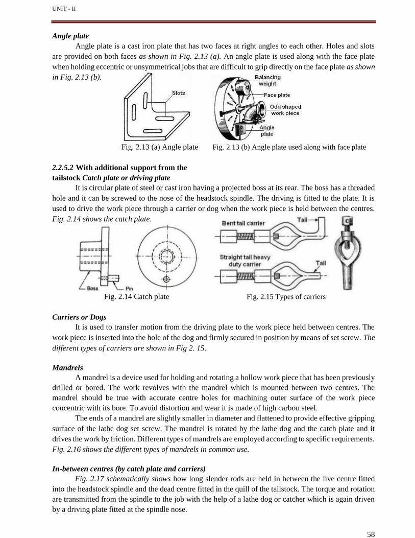
58
UNIT - II
Angle plate
Angle plate is a cast iron plate that has two faces at right angles to each other. Holes and slots
are provided on both faces as shown in Fig. 2.13 (a). An angle plate is used along with the face plate
when holding eccentric or unsymmetrical jobs that are difficult to grip directly on the face plate as shown
in Fig. 2.13 (b).
Fig. 2.13 (a) Angle plate Fig. 2.13 (b) Angle plate used along with face plate
2.2.5.2 With additional support from the
tailstock Catch plate or driving plate
It is circular plate of steel or cast iron having a projected boss at its rear. The boss has a threaded
hole and it can be screwed to the nose of the headstock spindle. The driving is fitted to the plate. It is
used to drive the work piece through a carrier or dog when the work piece is held between the centres.
Fig. 2.14 shows the catch plate.
Fig. 2.14 Catch plate Fig. 2.15 Types of carriers
Carriers or Dogs
It is used to transfer motion from the driving plate to the work piece held between centres. The
work piece is inserted into the hole of the dog and firmly secured in position by means of set screw. The
different types of carriers are shown in Fig 2. 15.
Mandrels
A mandrel is a device used for holding and rotating a hollow work piece that has been previously
drilled or bored. The work revolves with the mandrel which is mounted between two centres. The
mandrel should be true with accurate centre holes for machining outer surface of the work piece
concentric with its bore. To avoid distortion and wear it is made of high carbon steel.
The ends of a mandrel are slightly smaller in diameter and flattened to provide effective gripping
surface of the lathe dog set screw. The mandrel is rotated by the lathe dog and the catch plate and it
drives the work by friction. Different types of mandrels are employed according to specific requirements.
Fig. 2.16 shows the different types of mandrels in common use.
In-between centres (by catch plate and carriers)
Fig. 2.17 schematically shows how long slender rods are held in between the live centre fitted
into the headstock spindle and the dead centre fitted in the quill of the tailstock. The torque and rotation
are transmitted from the spindle to the job with the help of a lathe dog or catcher which is again driven
by a driving plate fitted at the spindle nose.
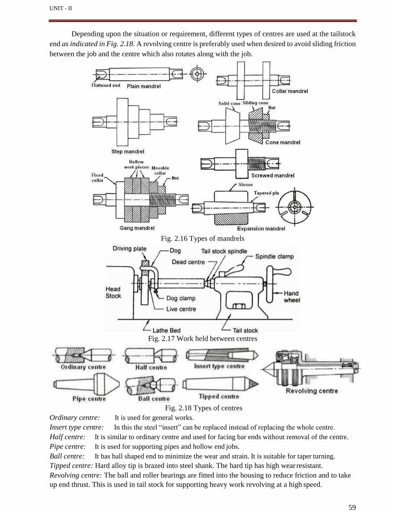
59
UNIT - II
Depending upon the situation or requirement, different types of centres are used at the tailstock
end as indicated in Fig. 2.18. A revolving centre is preferably used when desired to avoid sliding friction
between the job and the centre which also rotates along with the job.
Fig. 2.16 Types of mandrels
Fig. 2.17 Work held between centres
Fig. 2.18 Types of centres
Ordinary centre: It is used for general works.
Insert type centre: In this the steel “insert” can be replaced instead of replacing the whole centre.
Half centre: It is similar to ordinary centre and used for facing bar ends without removal of the centre.
Pipe centre: It is used for supporting pipes and hollow end jobs.
Ball centre: It has ball shaped end to minimize the wear and strain. It is suitable for taper turning.
Tipped centre: Hard alloy tip is brazed into steel shank. The hard tip has high wear resistant.
Revolving centre: The ball and roller bearings are fitted into the housing to reduce friction and to take
up end thrust. This is used in tail stock for supporting heavy work revolving at a high speed.
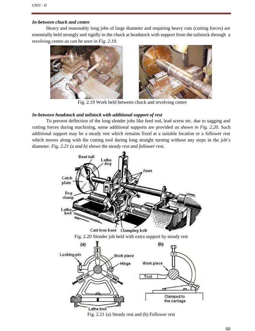
UNIT - II
60
In-between chuck and centre
Heavy and reasonably long jobs of large diameter and requiring heavy cuts (cutting forces) are
essentially held strongly and rigidly in the chuck at headstock with support from the tailstock through a
revolving centre as can be seen in Fig. 2.19.
Fig. 2.19 Work held between chuck and revolving centre
In-between headstock and tailstock with additional support of rest
To prevent deflection of the long slender jobs like feed rod, lead screw etc. due to sagging and
cutting forces during machining, some additional supports are provided as shown in Fig. 2.20. Such
additional support may be a steady rest which remains fixed at a suitable location or a follower rest
which moves along with the cutting tool during long straight turning without any steps in the job’s
diameter. Fig. 2.21 (a and b) shows the steady rest and follower rest.
Fig. 2.20 Slender job held with extra support by steady rest
Fig. 2.21 (a) Steady rest and (b) Follower rest
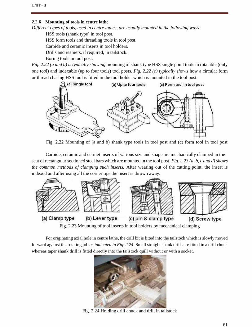
UNIT - II
61
2.2.6 Mounting of tools in centre lathe
Different types of tools, used in centre lathes, are usually mounted in the following ways:
HSS tools (shank type) in tool post.
HSS form tools and threading tools in tool post.
Carbide and ceramic inserts in tool holders.
Drills and reamers, if required, in tailstock.
Boring tools in tool post.
Fig. 2.22 (a and b) is typically showing mounting of shank type HSS single point tools in rotatable (only
one tool) and indexable (up to four tools) tool posts. Fig. 2.22 (c) typically shows how a circular form
or thread chasing HSS tool is fitted in the tool holder which is mounted in the tool post.
Fig. 2.22 Mounting of (a and b) shank type tools in tool post and (c) form tool in tool post
Carbide, ceramic and cermet inserts of various size and shape are mechanically clamped in the
seat of rectangular sectioned steel bars which are mounted in the tool post. Fig. 2.23 (a, b, c and d) shows
the common methods of clamping such inserts. After wearing out of the cutting point, the insert is
indexed and after using all the corner tips the insert is thrown away.
Fig. 2.23 Mounting of tool inserts in tool holders by mechanical clamping
For originating axial hole in centre lathe, the drill bit is fitted into the tailstock which is slowly moved
forward against the rotating job as indicated in Fig. 2.24. Small straight shank drills are fitted in a drill chuck
whereas taper shank drill is fitted directly into the tailstock quill without or with a socket.
Fig. 2.24 Holding drill chuck and drill in tailstock
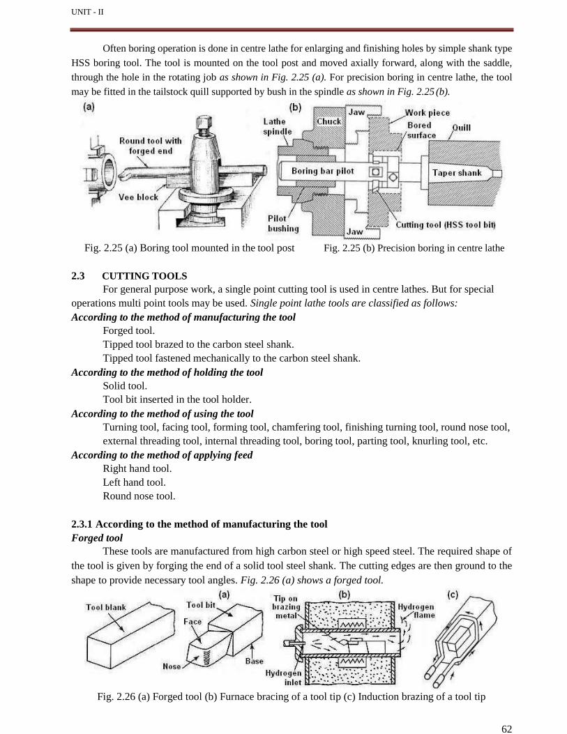
UNIT - II
62
Often boring operation is done in centre lathe for enlarging and finishing holes by simple shank type
HSS boring tool. The tool is mounted on the tool post and moved axially forward, along with the saddle,
through the hole in the rotating job as shown in Fig. 2.25 (a). For precision boring in centre lathe, the tool
may be fitted in the tailstock quill supported by bush in the spindle as shown in Fig. 2.25 (b).
Fig. 2.25 (a) Boring tool mounted in the tool post Fig. 2.25 (b) Precision boring in centre lathe
2.3 CUTTING TOOLS
For general purpose work, a single point cutting tool is used in centre lathes. But for special
operations multi point tools may be used. Single point lathe tools are classified as follows:
According to the method of manufacturing the tool
Forged tool.
Tipped tool brazed to the carbon steel shank.
Tipped tool fastened mechanically to the carbon steel shank.
According to the method of holding the tool
Solid tool.
Tool bit inserted in the tool holder.
According to the method of using the tool
Turning tool, facing tool, forming tool, chamfering tool, finishing turning tool, round nose tool,
external threading tool, internal threading tool, boring tool, parting tool, knurling tool, etc.
According to the method of applying feed
Right hand tool.
Left hand tool.
Round nose tool.
2.3.1 According to the method of manufacturing the tool
Forged tool
These tools are manufactured from high carbon steel or high speed steel. The required shape of
the tool is given by forging the end of a solid tool steel shank. The cutting edges are then ground to the
shape to provide necessary tool angles. Fig. 2.26 (a) shows a forged tool.
Fig. 2.26 (a) Forged tool (b) Furnace bracing of a tool tip (c) Induction brazing of a tool tip
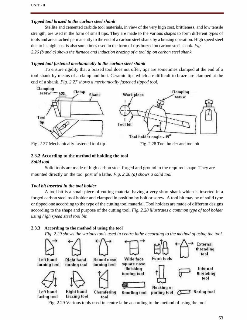
UNIT - II
63
Tipped tool brazed to the carbon steel shank
Stellite and cemented carbide tool materials, in view of the very high cost, brittleness, and low tensile
strength, are used in the form of small tips. They are made to the various shapes to form different types of
tools and are attached permanently to the end of a carbon steel shank by a brazing operation. High speed steel
due to its high cost is also sometimes used in the form of tips brazed on carbon steel shank. Fig.
2.26 (b and c) shows the furnace and induction brazing of a tool tip on carbon steel shank.
Tipped tool fastened mechanically to the carbon steel shank
To ensure rigidity that a brazed tool does not offer, tips are sometimes clamped at the end of a
tool shank by means of a clamp and bolt. Ceramic tips which are difficult to braze are clamped at the
end of a shank. Fig. 2.27 shows a mechanically fastened tipped tool.
Fig. 2.27 Mechanically fastened tool tip Fig. 2.28 Tool holder and tool bit
2.3.2 According to the method of holding the tool
Solid tool
Solid tools are made of high carbon steel forged and ground to the required shape. They are
mounted directly on the tool post of a lathe. Fig. 2.26 (a) shows a solid tool.
Tool bit inserted in the tool holder
A tool bit is a small piece of cutting material having a very short shank which is inserted in a
forged carbon steel tool holder and clamped in position by bolt or screw. A tool bit may be of solid type
or tipped one according to the type of the cutting tool material. Tool holders are made of different designs
according to the shape and purpose of the cutting tool. Fig. 2.28 illustrates a common type of tool holder
using high speed steel tool bit.
2.3.3 According to the method of using the tool
Fig. 2.29 shows the various tools used in centre lathe according to the method of using the tool.
Fig. 2.29 Various tools used in centre lathe according to the method of using the tool
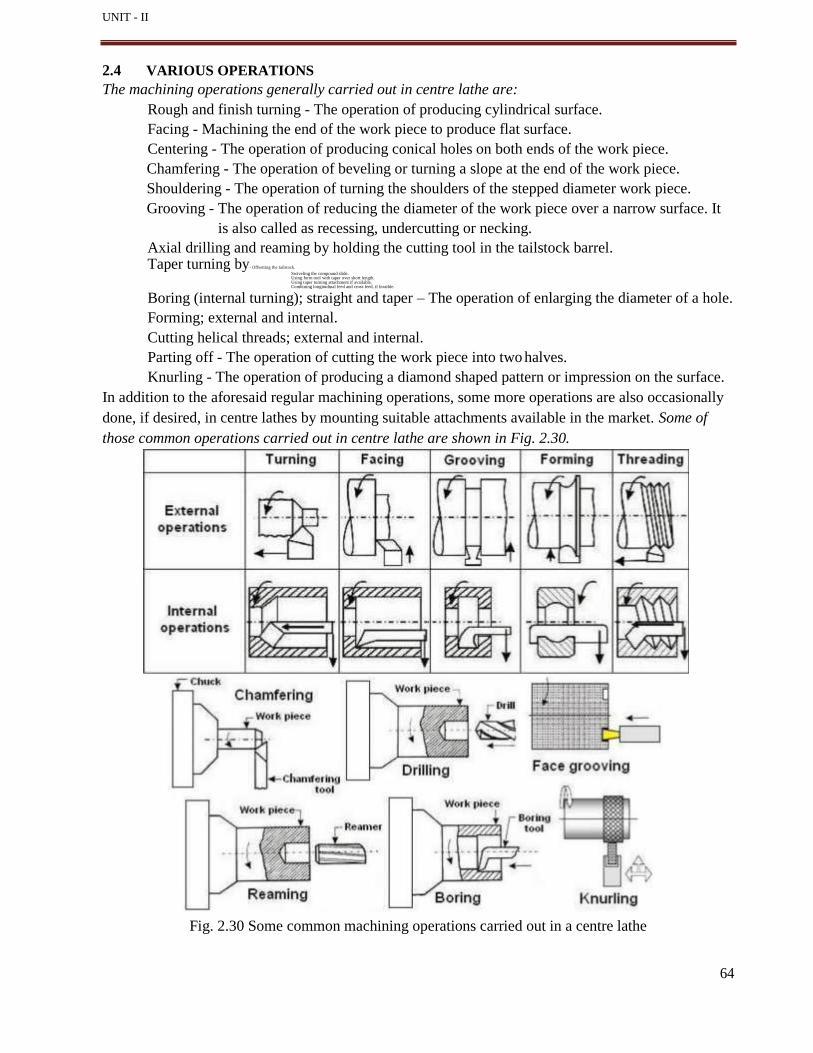
UNIT - II
2.4 VARIOUS OPERATIONS
The machining operations generally carried out in centre lathe are:
Rough and finish turning - The operation of producing cylindrical surface.
Facing - Machining the end of the work piece to produce flat surface.
Centering - The operation of producing conical holes on both ends of the work piece.
Chamfering - The operation of beveling or turning a slope at the end of the work piece.
Shouldering - The operation of turning the shoulders of the stepped diameter work piece.
Grooving - The operation of reducing the diameter of the work piece over a narrow surface. It
is also called as recessing, undercutting or necking.
Axial drilling and reaming by holding the cutting tool in the tailstock barrel. Taper turning by- Offsetting the tailstock.
Swiveling the compound slide. Using form tool with taper over short length. Using taper turning attachment if available. Combining longitudinal feed and cross feed, if feasible.
Boring (internal turning); straight and taper – The operation of enlarging the diameter of a hole.
Forming; external and internal.
Cutting helical threads; external and internal.
Parting off - The operation of cutting the work piece into two halves.
Knurling - The operation of producing a diamond shaped pattern or impression on the surface.
In addition to the aforesaid regular machining operations, some more operations are also occasionally
done, if desired, in centre lathes by mounting suitable attachments available in the market. Some of
those common operations carried out in centre lathe are shown in Fig. 2.30.
Fig. 2.30 Some common machining operations carried out in a centre lathe
64
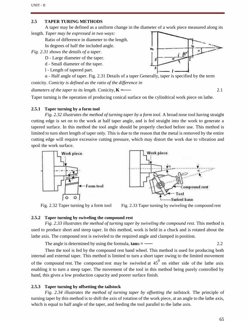
UNIT - II
65
2.5 TAPER TURING METHODS
A taper may be defined as a uniform change in the diameter of a work piece measured along its
length. Taper may be expressed in two ways:
Ratio of difference in diameter to the length.
In degrees of half the included angle.
Fig. 2.31 shows the details of a taper.
D - Large diameter of the taper.
d - Small diameter of the taper.
l - Length of tapered part.
α - Half angle of taper. Fig. 2.31 Details of a taper Generally, taper is specified by the term
conicity. Conicity is defined as the ratio of the difference in
diameters of the taper to its length. Conicity, K = 2.1
Taper turning is the operation of producing conical surface on the cylindrical work piece on lathe.
2.5.1 Taper turning by a form tool
Fig. 2.32 illustrates the method of turning taper by a form tool. A broad nose tool having straight
cutting edge is set on to the work at half taper angle, and is fed straight into the work to generate a
tapered surface. In this method the tool angle should be properly checked before use. This method is
limited to turn short length of taper only. This is due to the reason that the metal is removed by the entire
cutting edge will require excessive cutting pressure, which may distort the work due to vibration and
spoil the work surface.
Fig. 2.32 Taper turning by a form tool Fig. 2.33 Taper turning by swiveling the compound rest
2.5.2 Taper turning by swiveling the compound rest
Fig. 2.33 illustrates the method of turning taper by swiveling the compound rest. This method is
used to produce short and steep taper. In this method, work is held in a chuck and is rotated about the
lathe axis. The compound rest is swiveled to the required angle and clamped in position.
The angle is determined by using the formula, tanα = 2.2
Then the tool is fed by the compound rest hand wheel. This method is used for producing both
internal and external taper. This method is limited to turn a short taper owing to the limited movement
of the compound rest. The compound rest may be swiveled at 450
on either side of the lathe axis
enabling it to turn a steep taper. The movement of the tool in this method being purely controlled by
hand, this gives a low production capacity and poorer surface finish.
2.5.3 Taper turning by offsetting the tailstock
Fig. 2.34 illustrates the method of turning taper by offsetting the tailstock. The principle of
turning taper by this method is to shift the axis of rotation of the work piece, at an angle to the lathe axis,
which is equal to half angle of the taper, and feeding the tool parallel to the lathe axis.
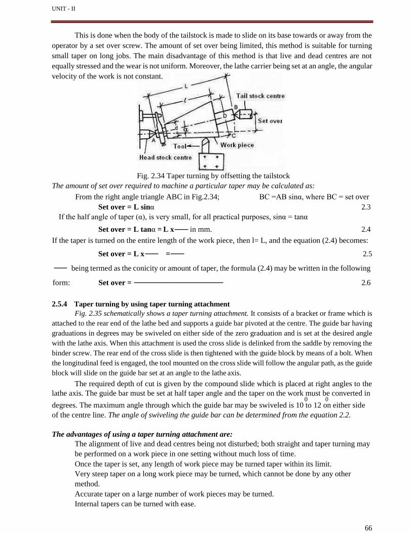
UNIT - II
This is done when the body of the tailstock is made to slide on its base towards or away from the
operator by a set over screw. The amount of set over being limited, this method is suitable for turning
small taper on long jobs. The main disadvantage of this method is that live and dead centres are not
equally stressed and the wear is not uniform. Moreover, the lathe carrier being set at an angle, the angular
velocity of the work is not constant.
Fig. 2.34 Taper turning by offsetting the tailstock
The amount of set over required to machine a particular taper may be calculated as:
From the right angle triangle ABC in Fig.2.34; BC =AB sinα, where BC = set over
Set over = L sinα 2.3
If the half angle of taper (α), is very small, for all practical purposes, sinα = tanα
Set over = L tanα = L x in mm. 2.4
If the taper is turned on the entire length of the work piece, then l= L, and the equation (2.4) becomes:
Set over = L x = 2.5
being termed as the conicity or amount of taper, the formula (2.4) may be written in the following
form: Set over = 2.6
2.5.4 Taper turning by using taper turning attachment
Fig. 2.35 schematically shows a taper turning attachment. It consists of a bracket or frame which is
attached to the rear end of the lathe bed and supports a guide bar pivoted at the centre. The guide bar having
graduations in degrees may be swiveled on either side of the zero graduation and is set at the desired angle
with the lathe axis. When this attachment is used the cross slide is delinked from the saddle by removing the
binder screw. The rear end of the cross slide is then tightened with the guide block by means of a bolt. When
the longitudinal feed is engaged, the tool mounted on the cross slide will follow the angular path, as the guide
block will slide on the guide bar set at an angle to the lathe axis.
The required depth of cut is given by the compound slide which is placed at right angles to the
lathe axis. The guide bar must be set at half taper angle and the taper on the work must be converted in 0 0
degrees. The maximum angle through which the guide bar may be swiveled is 10 to 12 on either side
of the centre line. The angle of swiveling the guide bar can be determined from the equation 2.2.
The advantages of using a taper turning attachment are:
The alignment of live and dead centres being not disturbed; both straight and taper turning may
be performed on a work piece in one setting without much loss of time.
Once the taper is set, any length of work piece may be turned taper within its limit.
Very steep taper on a long work piece may be turned, which cannot be done by any other
method.
Accurate taper on a large number of work pieces may be turned.
Internal tapers can be turned with ease.
66
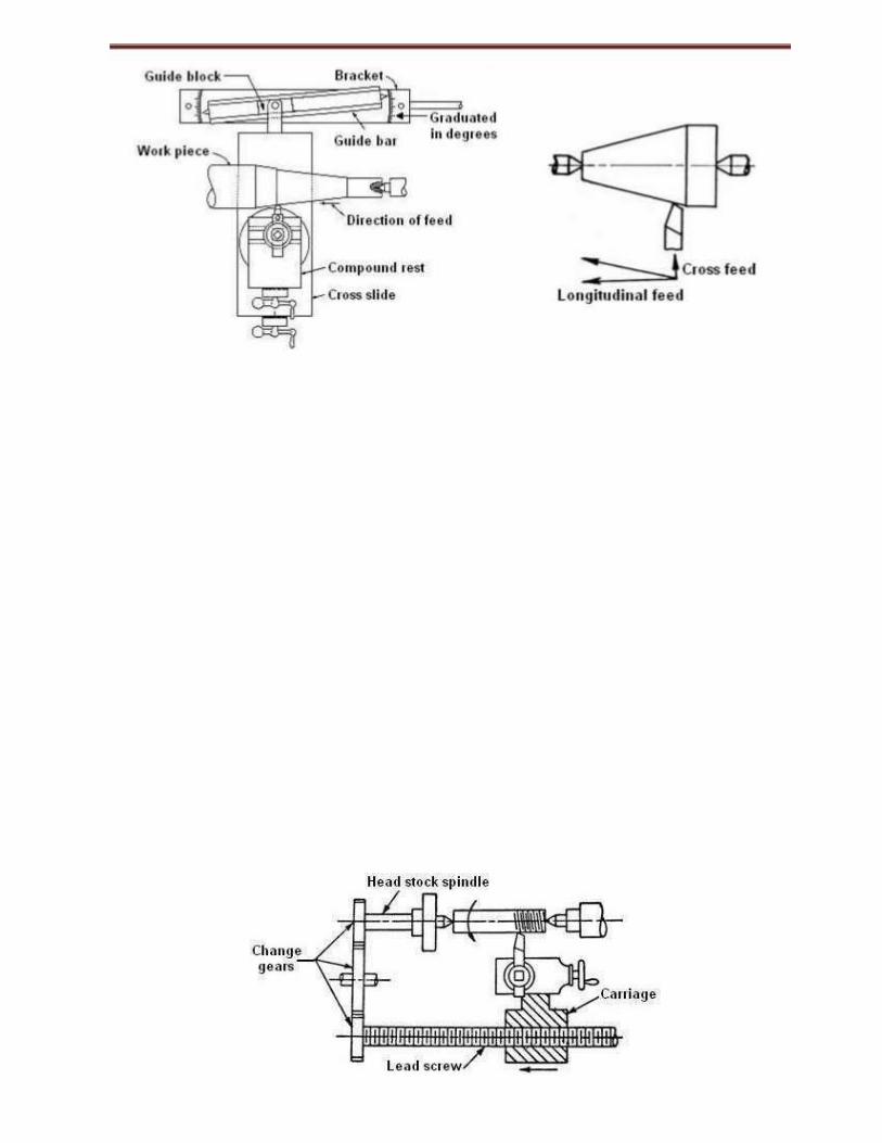

ERROR: undefined OFFENDING COMMAND: f‘
STACK:


