29
1 Principles of turbomachinery

1
Principles of turbomachinery

2
Flow Mechanism in the impeller of a turbomachine
Notations:
U: peripheral velocity.
C: absolute velocity
W: relative velocity
ALL VELOCITIES ARE IN m/s

3
t=t0
t=t1
t=t2
Relative velocity and the path of a particle
Index:Velocity relative to an observer sitting on the green carriage
Velocity of the green carriage itself
Absolute velocity (velocity relative to an observer on the ground)

4
Relative velocity and the path of a particle inside the blade passage
1 21
2
1
2Absolute Path

5
Schematic of vane congruent flow

6
Velocity triangle(in case of vane congruent flows)
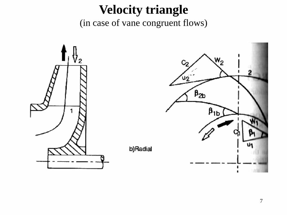
7
Velocity triangle(in case of vane congruent flows)

8
Velocity triangle
C: absolute velocity
W: relative velocity
U: peripheral velocity of the blade
Cu: peripheral (whirl) component of the absolute velocity
Cm: meridional component of the absolute velocity
1) Angle (β) is measured between positive direction of W and negative direction of U.
C W
UCu
Cm
α β
2) Angle (α) is measured between positive direction of C and positive direction of U
NOTE:
INDEX:
9
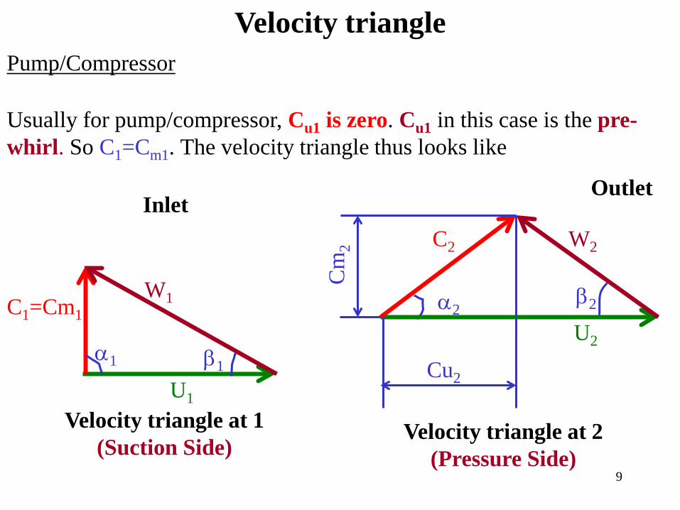
Velocity trianglePump/Compressor
U1
W1C1=Cm1
α1 β1
U2
C2 W2
Cm
2
Cu2
β2α2
Velocity triangle at 1(Suction Side)
Velocity triangle at 2(Pressure Side)
Usually for pump/compressor, Cu1 is zero. Cu1 in this case is the pre-whirl. So C1=Cm1. The velocity triangle thus looks like
InletOutlet

10
Velocity triangleTurbine
U1
W1C1=Cm1
α1 β1U2
C2 W2
Cm
2
Cu2
β2α2
Velocity triangle at 1(Suction Side)
Velocity triangle at 2(Pressure Side)
Ideally Cu1 is zero for improved efficiency. Cu1 in this case is the exit whirl. So C1=Cm1. The velocity triangle thus looks like
Inlet Outlet
11
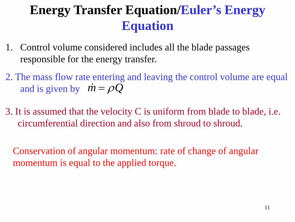
Energy Transfer Equation/Euler’s Energy Equation
Conservation of angular momentum: rate of change of angular momentum is equal to the applied torque.
1. Control volume considered includes all the blade passages responsible for the energy transfer.
m Qρ=2. The mass flow rate entering and leaving the control volume are equal
and is given by
3. It is assumed that the velocity C is uniform from blade to blade, i.e. circumferential direction and also from shroud to shroud.

12
W2
C2
U2
W1C1
U1
Control Volume
r1L1
r2
L2
2
1

13
Derivation of Euler’s Energy Equation
Torque (T): 2 2 1 1( )T m C L C L= −
cos , 1,2i i iL r iα= =&
( )2 2 2 1 1 1
2 2 1 1
( cos cos )
u u
T m C r C rm r C rC
α α= −
= −
L2L1

14
Euler’s Energy Equation
2 2 1 1
2 2 1 1
( )( )
bl
u u
u u
P Tm r C rCm U C U C
ωω
∞ =
= −
= −
Neglecting friction
Specific Work:
2 2 1 1( )blbl u u
PW U C U Cm∞
∞ = = −
Euler’s energy equation (also called Euler’s turbine equation)
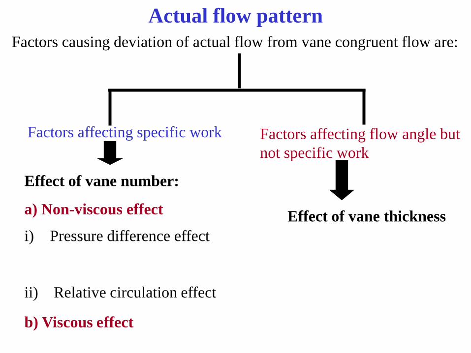
Actual flow patternFactors causing deviation of actual flow from vane congruent flow are:
Factors affecting specific work Factors affecting flow angle but not specific work
Effect of vane number:
a) Non-viscous effect
b) Viscous effect
i) Pressure difference effect
ii) Relative circulation effect
Effect of vane thickness

Actual flow patternPressure difference effect
s
1
2
+-
++
++
-
--
-
- ++
++
-
--
-
-
2
1

Actual flow patternRelative circulation effect(in radial impellers only)
Vane Congruent Flow Circulatory Flow
Resultant actual flow in a pump/compressor
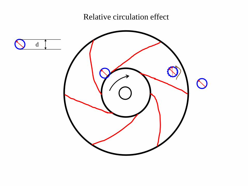
Relative circulation effect
d
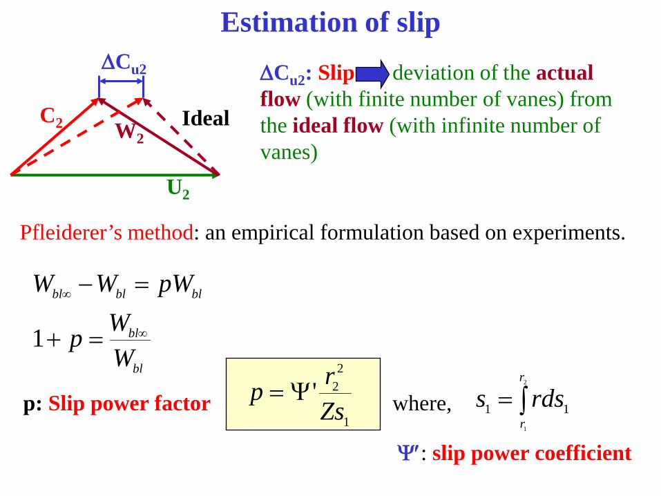
Estimation of slip
bl
bl
blblbl
WWp
pWWW
∞
∞
=+
=−
1
Pfleiderer’s method: an empirical formulation based on experiments.
U2
C2 W2
∆Cu2
Ideal
∆Cu2: Slip deviation of the actual flow (with finite number of vanes) from the ideal flow (with infinite number of vanes)
p: Slip power factor where,1
22'
Zsrp Ψ= ∫=
2
1
11
r
rrdss
Ψ′: slip power coefficient

Estimation of slip
Special cases:
a) Radial flow impeller: ds1=dr
b) Axial flow impeller: r is constant
2
2
11
1'2
−
Ψ=
rrZ
p
Zerp 'Ψ=

Estimation of slip
Ψ′ is a function of β2b, the impeller type (radial/axial) and the system at the exit of the impeller.
bbk 2
2 ,60
1' ββ
+=Ψ is in degrees.
For radial and mixed flow impellers:
with guide vanes after impeller, k=0.6
with spiral casing after impeller, k=0.65 to 0.85
with vaneless diffuser after impeller, k=0.85 to 1.0,
For axial flow impellers, k=1.0 to 1.2

Stodola’s Method of determining Slip
2reldC ω ′
=
2
2
2UD
ω =
2
2rel
U dCD
′=
where,
so,
From ∆ABC,
22
sin bd d DZβπ′ = =
22 2
22
2
sinsin
b
bU D
ZCrel UD Z
βπ π β= = SLIP
22
DSZ
π=
2uC2uC ∞
Linear relative velocity of this eddy is:
Source: Shepherd
SLIP

U2
C2 W2
∆Cu2
Ideal
Stodola’s slip factor (s)'2
2
u
u
CsC
=
22 2
2
sin bu
u
C UZ
C
π β∞
∞
−=
2 2
2
sin1 b
u
UC Z
π β
∞
= −
2 2
2 2 2
sin1cot
b
m b
UsU C Z
π ββ
= − −
Thus 2 conclusions can be drawn: as Z →∞, s → 1
as Q increases, Cm2 increases and s reduces
Can you find expressions for Wbl∞ and Wbl?
2
2
u
u
CC ∞
=
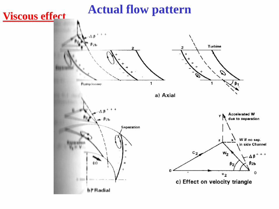
Actual flow patternViscous effect

Actual flow patternVane thickness effect
β1b
tu1
bu
ttβsin
=
Applying continuity across suction edge (1)
&ZDS π
=No. of blades
S1 tu1
tu2
β1b
β2b
1
II
I
2
S2
( )1 1 1 1.1. .1.mI u mV S C S t C= = −
1m mIC C>
11
1 1m mI
u
SC CS t
= −

Actual flow patternVane thickness effect
Along pressure edge (2)
22
2 2m mII
u
SC CS t
= −
2m mIIC C>
What is the effect of changing Cm on flow directions?
S1 tu1
tu2
β1b
β2b
1
II
I
2
S2

Actual flow patternVane thickness effect
CmI
Cm1 W1
WI
β1 βI
β1 > βI
Suction edge
U1
Cm
II
Cm
2U2
W2
WIIC3
C2
βIIβ2
β2 > βII
Pressure edge

(Z)
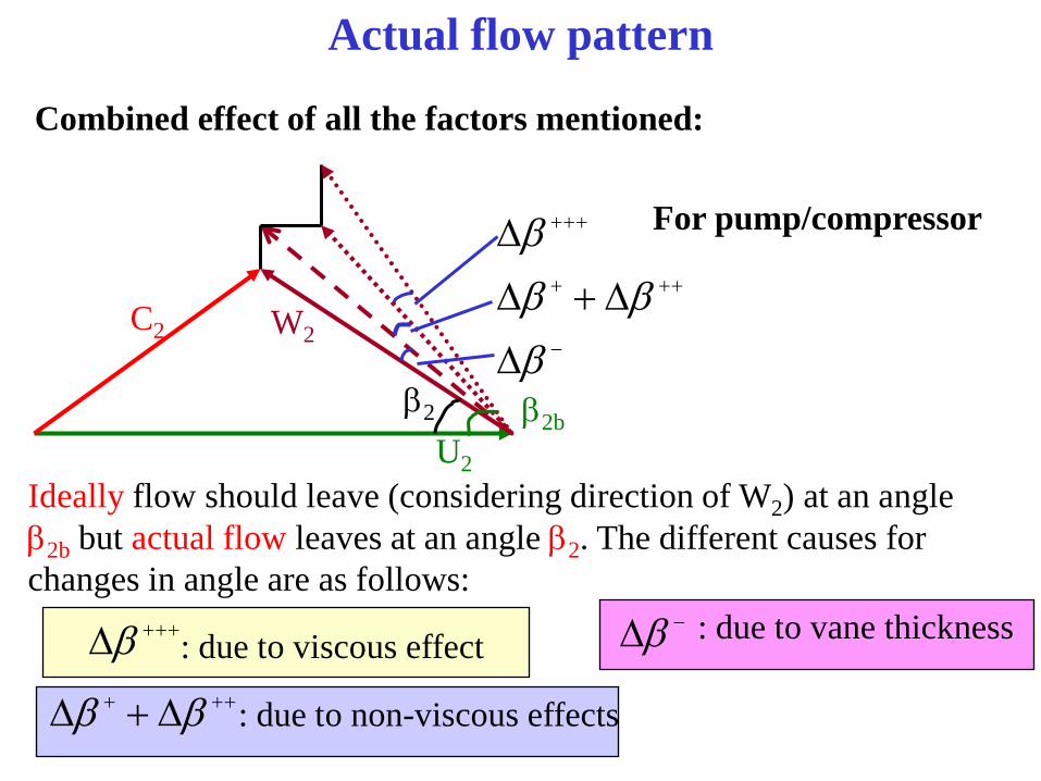
Actual flow pattern
Combined effect of all the factors mentioned:
For pump/compressor
C2 W2
U2
β2
−
+++
+++
∆
∆+∆
∆
βββ
β
β2b
Ideally flow should leave (considering direction of W2) at an angle β2b but actual flow leaves at an angle β2. The different causes for changes in angle are as follows:
+++∆β : due to viscous effect+++ ∆+∆ ββ : due to non-viscous effects
−∆β : due to vane thickness


