ASIAUnits 602-603 6/F Lakeside 1No.8 Science Park West AvenuePhase Two, Hong Kong Science ParkPak Shek Kok, Tai Po, N.T.Hong KongTel: (852) 2 191 3830Fax: (852) 2 389 5803
Data sheets are for initial product selection and comparison. Contact Esterline Power Systems prior to choosing a component.
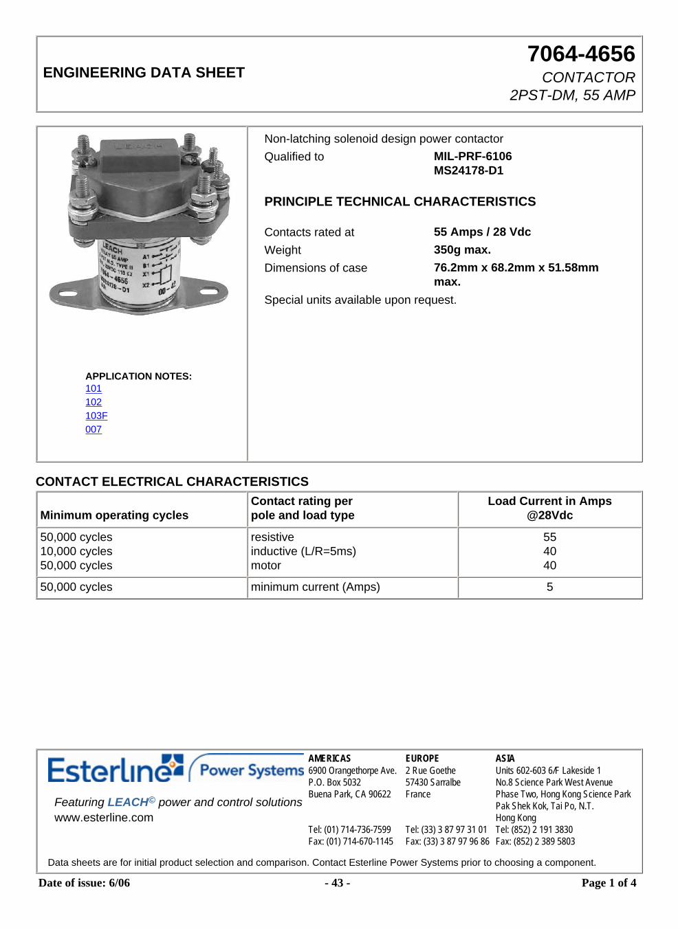
Date of issue: 6/06 - 43 - Page 1 of 4
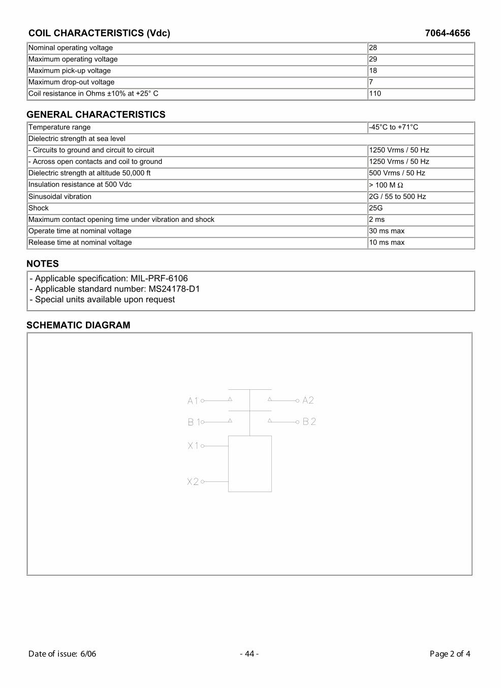
COIL CHARACTERISTICS (Vdc) 7064-4656
Nominal operating voltage 28Maximum operating voltage 29Maximum pick-up voltage 18Maximum drop-out voltage 7Coil resistance in Ohms ±10% at +25° C 110
GENERAL CHARACTERISTICSTemperature range -45°C to +71°CDielectric strength at sea level- Circuits to ground and circuit to circuit 1250 Vrms / 50 Hz- Across open contacts and coil to ground 1250 Vrms / 50 HzDielectric strength at altitude 50,000 ft 500 Vrms / 50 HzInsulation resistance at 500 Vdc > 100 M ΩSinusoidal vibration 2G / 55 to 500 HzShock 25GMaximum contact opening time under vibration and shock 2 msOperate time at nominal voltage 30 ms maxRelease time at nominal voltage 10 ms max
NOTES
- Applicable specification: MIL-PRF-6106- Applicable standard number: MS24178-D1- Special units available upon request
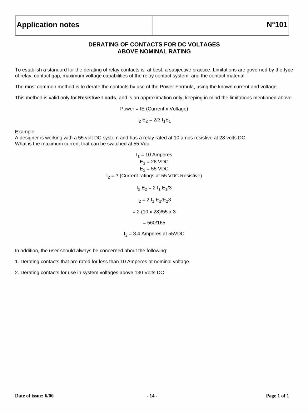
DERATING OF CONTACTS FOR DC VOLTAGESABOVE NOMINAL RATING
To establish a standard for the derating of relay contacts is, at best, a subjective practice. Limitations are governed by the type of relay, contact gap, maximum voltage capabilities of the relay contact system, and the contact material.
The most common method is to derate the contacts by use of the Power Formula, using the known current and voltage.
This method is valid only for Resistive Loads, and is an approximation only; keeping in mind the limitations mentioned above.
Power = IE (Current x Voltage)
I2 E2 = 2/3 I1E1
Example:A designer is working with a 55 volt DC system and has a relay rated at 10 amps resistive at 28 volts DC.What is the maximum current that can be switched at 55 Vdc.
I1 = 10 AmperesE1 = 28 VDCE2 = 55 VDC
I2 = ? (Current ratings at 55 VDC Resistive)
I2 E2 = 2 I1 E1/3
I2 = 2 I1 E1/E23
= 2 (10 x 28)/55 x 3
= 560/165
I2 = 3.4 Amperes at 55VDC
In addition, the user should always be concerned about the following:
1. Derating contacts that are rated for less than 10 Amperes at nominal voltage.
2. Derating contacts for use in system voltages above 130 Volts DC
Date of issue: 6/00 - 14 - Page 1 of 1
Application notes N°102
RELAYS AND TEMPERATURE VARIATIONS
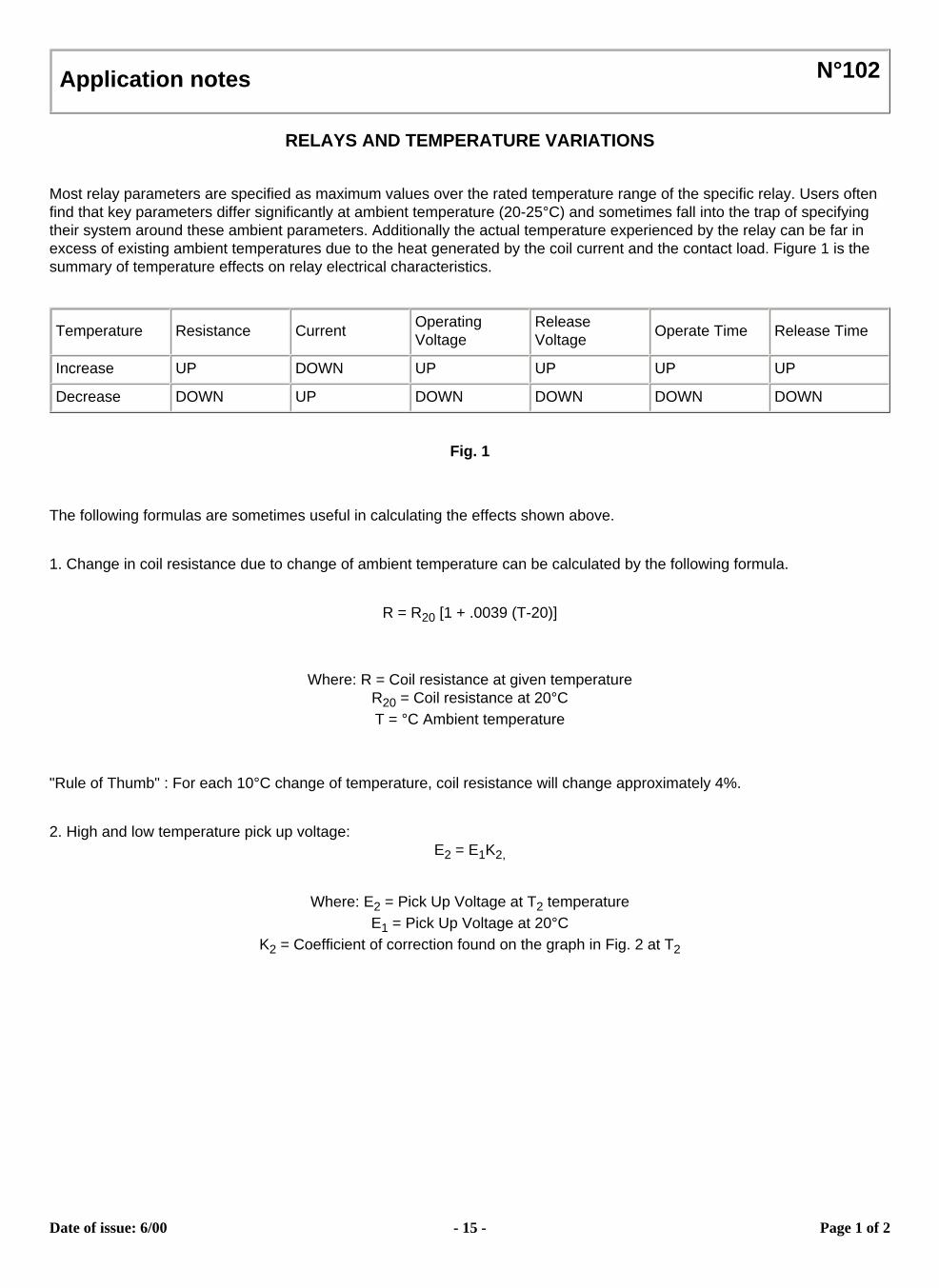
Most relay parameters are specified as maximum values over the rated temperature range of the specific relay. Users often find that key parameters differ significantly at ambient temperature (20-25°C) and sometimes fall into the trap of specifying their system around these ambient parameters. Additionally the actual temperature experienced by the relay can be far in excess of existing ambient temperatures due to the heat generated by the coil current and the contact load. Figure 1 is the summary of temperature effects on relay electrical characteristics.
Temperature Resistance Current Operating Voltage
Release Voltage Operate Time Release Time
Increase UP DOWN UP UP UP UP
Decrease DOWN UP DOWN DOWN DOWN DOWN
Fig. 1
The following formulas are sometimes useful in calculating the effects shown above.
1. Change in coil resistance due to change of ambient temperature can be calculated by the following formula.
R = R20 [1 + .0039 (T-20)]
Where: R = Coil resistance at given temperatureR20 = Coil resistance at 20°CT = °C Ambient temperature
"Rule of Thumb" : For each 10°C change of temperature, coil resistance will change approximately 4%.
2. High and low temperature pick up voltage:E2 = E1K2,
Where: E2 = Pick Up Voltage at T2 temperatureE1 = Pick Up Voltage at 20°C
K2 = Coefficient of correction found on the graph in Fig. 2 at T2
Date of issue: 6/00 - 15 - Page 1 of 2
3. Calculation of coil temperature rise when R initial and R final are known:
Delta T = (234.5 + T1) (R2/R1 - 1)Delta T = Temperature rise (°C)T1 = Initial temperature (°C)R1 = Initial resistance (Ohms)R2 = Final resistance (Ohms)R2 = K2R1
Temperature can also be found by making the R2/R1 ratio = thecoefficient of correction graph in Fig. 2, and then finding the corresponding temperature.
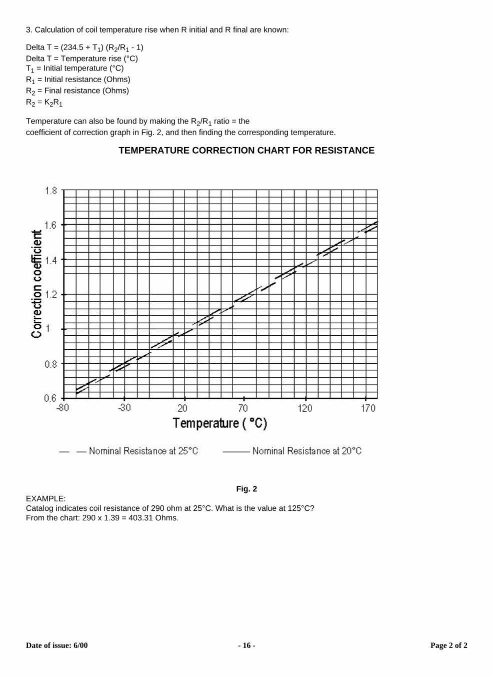
TEMPERATURE CORRECTION CHART FOR RESISTANCE
Fig. 2EXAMPLE:Catalog indicates coil resistance of 290 ohm at 25°C. What is the value at 125°C?From the chart: 290 x 1.39 = 403.31 Ohms.
Date of issue: 6/00 - 16 - Page 2 of 2
Application notes N°103F
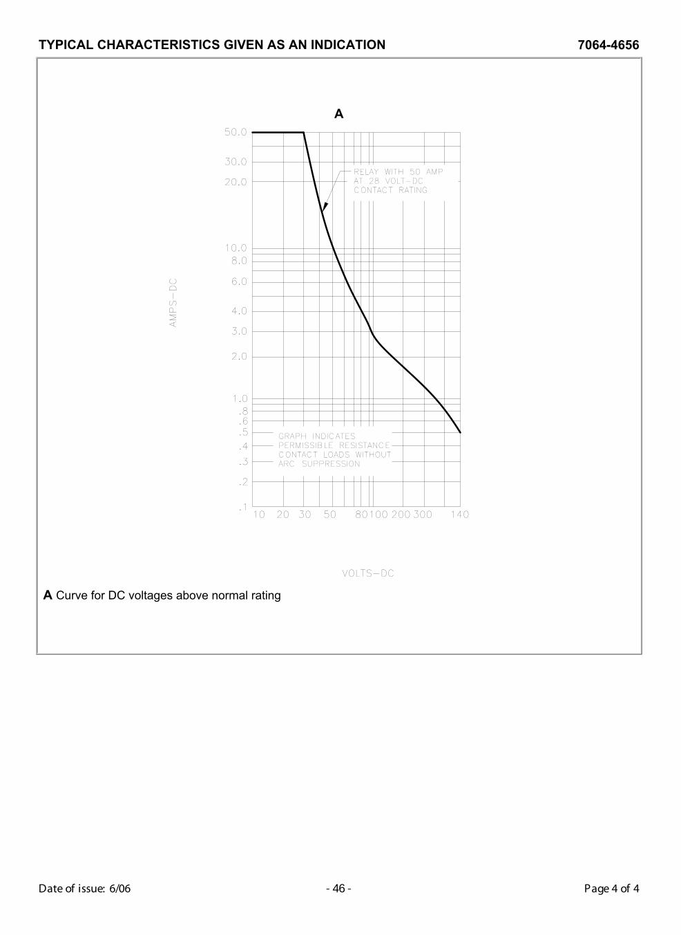
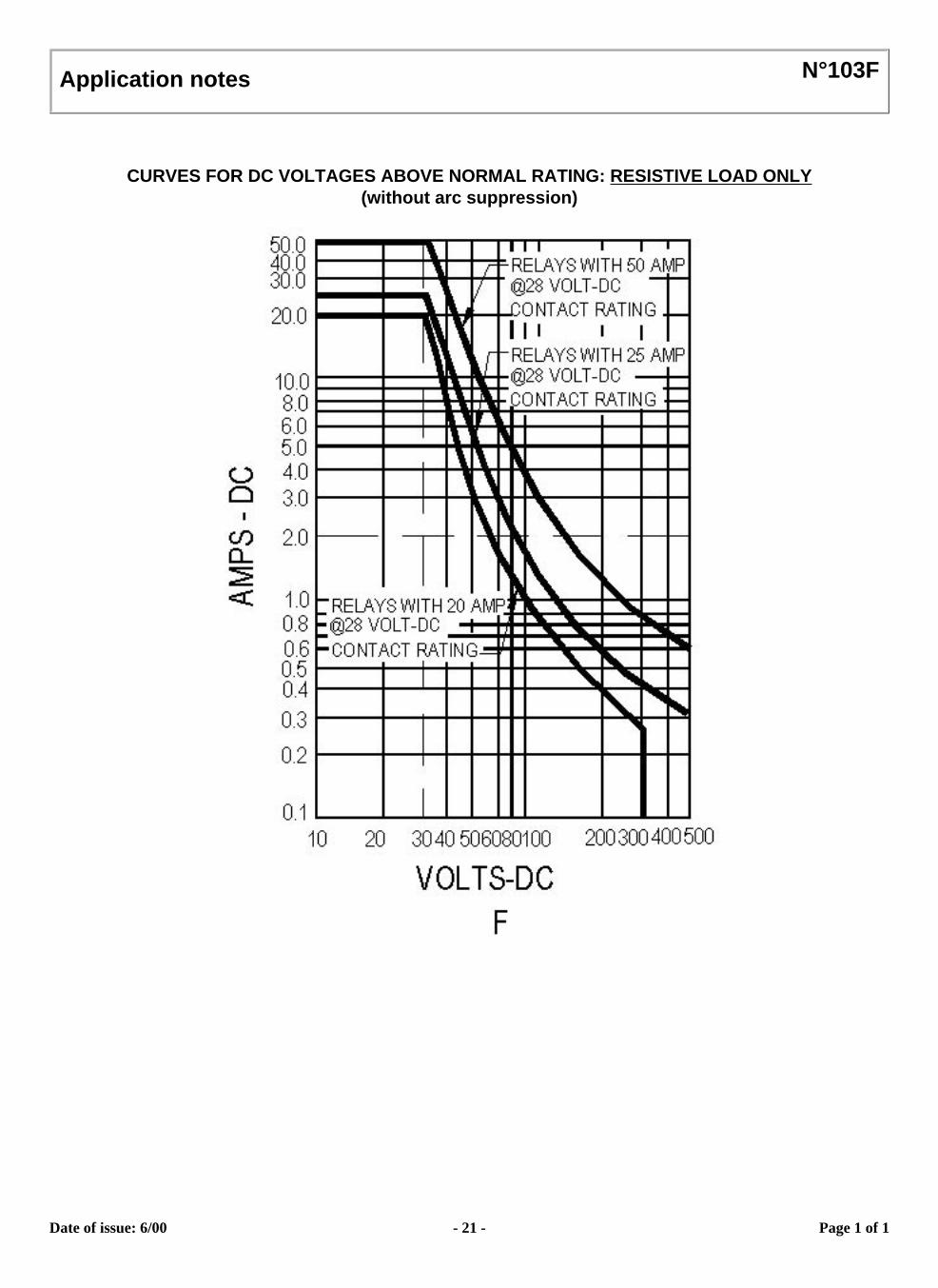
CURVES FOR DC VOLTAGES ABOVE NORMAL RATING: RESISTIVE LOAD ONLY(without arc suppression)
Date of issue: 6/00 - 21 - Page 1 of 1
Application notes N°007
SUPPRESSOR DEVICES FOR RELAY COILS
The inductive nature of relay coils allows them to create magnetic forces which are converted to mechanical movements to operate contact systems. When voltage is applied to a coil, the resulting current generates a magnetic flux, creating mechanical work. Upon deenergizing the coil, the collapasing magnetic field induces a reverse voltage (also known as back EMF) which tends to maintain current flow in the coil. The induced voltage level mainly depends on the duration of the deenergization. The faster the switch-off, the higher the induced voltage.
All coil suppression networks are based on a reduction of speed of current decay. This reduction may also slow down the opening of contacts, adversly effecting contact life and reliability. Therefore, it is very important to have a clear understanding of these phenomena when designing a coil suppression circuitry.
Typical coil characteristics
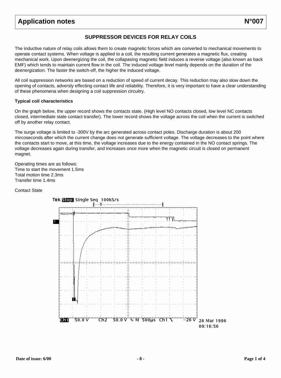
On the graph below, the upper record shows the contacts state. (High level NO contacts closed, low level NC contacts closed, intermediate state contact transfer). The lower record shows the voltage across the coil when the current is switched off by another relay contact.
The surge voltage is limited to -300V by the arc generated across contact poles. Discharge duration is about 200 mircoseconds after which the current change does not generate sufficient voltage. The voltage decreases to the point where the contacts start to move, at this time, the voltage increases due to the energy contained in the NO contact springs. The voltage decreases again during transfer, and increases once more when the magnetic circuit is closed on permanent magnet.
Operating times are as follows:Time to start the movement 1.5msTotal motion time 2.3msTransfer time 1.4ms
Contact State
Date of issue: 6/00 - 8 - Page 1 of 4
Types of suppressors:
Passive devices.
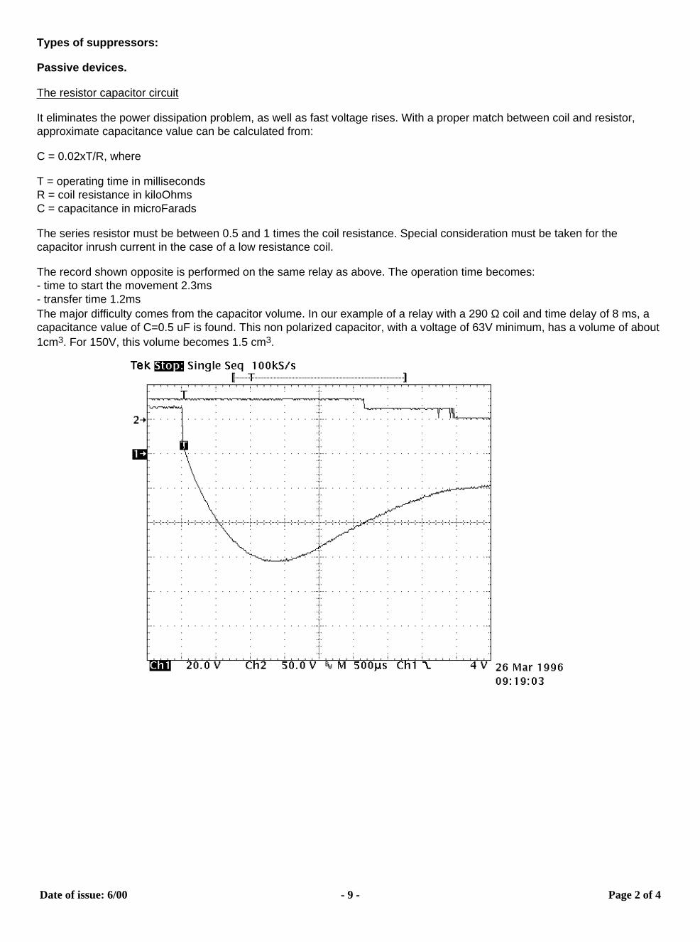
The resistor capacitor circuit
It eliminates the power dissipation problem, as well as fast voltage rises. With a proper match between coil and resistor, approximate capacitance value can be calculated from:
C = 0.02xT/R, where
T = operating time in millisecondsR = coil resistance in kiloOhmsC = capacitance in microFarads
The series resistor must be between 0.5 and 1 times the coil resistance. Special consideration must be taken for the capacitor inrush current in the case of a low resistance coil.
The record shown opposite is performed on the same relay as above. The operation time becomes:- time to start the movement 2.3ms- transfer time 1.2msThe major difficulty comes from the capacitor volume. In our example of a relay with a 290 Ω coil and time delay of 8 ms, a capacitance value of C=0.5 uF is found. This non polarized capacitor, with a voltage of 63V minimum, has a volume of about 1cm3. For 150V, this volume becomes 1.5 cm3.
Date of issue: 6/00 - 9 - Page 2 of 4
The bifilar coil
The principle is to wind on the magnetic circuit of the main coil a second coil shorted on itself. By a proper adaptation of the internal resistance of this second coil it is possible to find an acceptable equilibrium between surge voltage and reduction of the opening speed. To be efficient at fast voltage changes, the coupling of two coils must be perfect. This implies embedded windings. The volume occupied by the second coil reduces the efficiency of the main coil and results in higher coil power consumption. This method cannot be applied efficiently to products not specifically designed for this purpose.
The resistor (parallel with the coil)For efficient action, the resistor must be of the same order of magnitude as the coil resistance. A resistor 1.5 times the coil resistance will limit the surge to 1.5 times the supply voltage. Release time and opening speed are moderately affected. The major problem is the extra power dissipated.
Semi-conductor devices
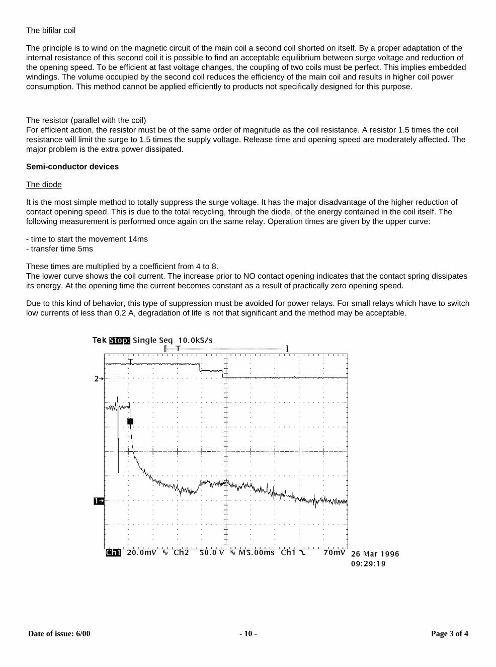
The diode
It is the most simple method to totally suppress the surge voltage. It has the major disadvantage of the higher reduction of contact opening speed. This is due to the total recycling, through the diode, of the energy contained in the coil itself. The following measurement is performed once again on the same relay. Operation times are given by the upper curve:
- time to start the movement 14ms- transfer time 5ms
These times are multiplied by a coefficient from 4 to 8.The lower curve shows the coil current. The increase prior to NO contact opening indicates that the contact spring dissipates its energy. At the opening time the current becomes constant as a result of practically zero opening speed.
Due to this kind of behavior, this type of suppression must be avoided for power relays. For small relays which have to switch low currents of less than 0.2 A, degradation of life is not that significant and the method may be acceptable.
Date of issue: 6/00 - 10 - Page 3 of 4
The diode + resistor network
It eliminates the inconvenience of the resistor alone, explained above, and it limits the action of a single diode. It is now preferred to used the diode + zener network.
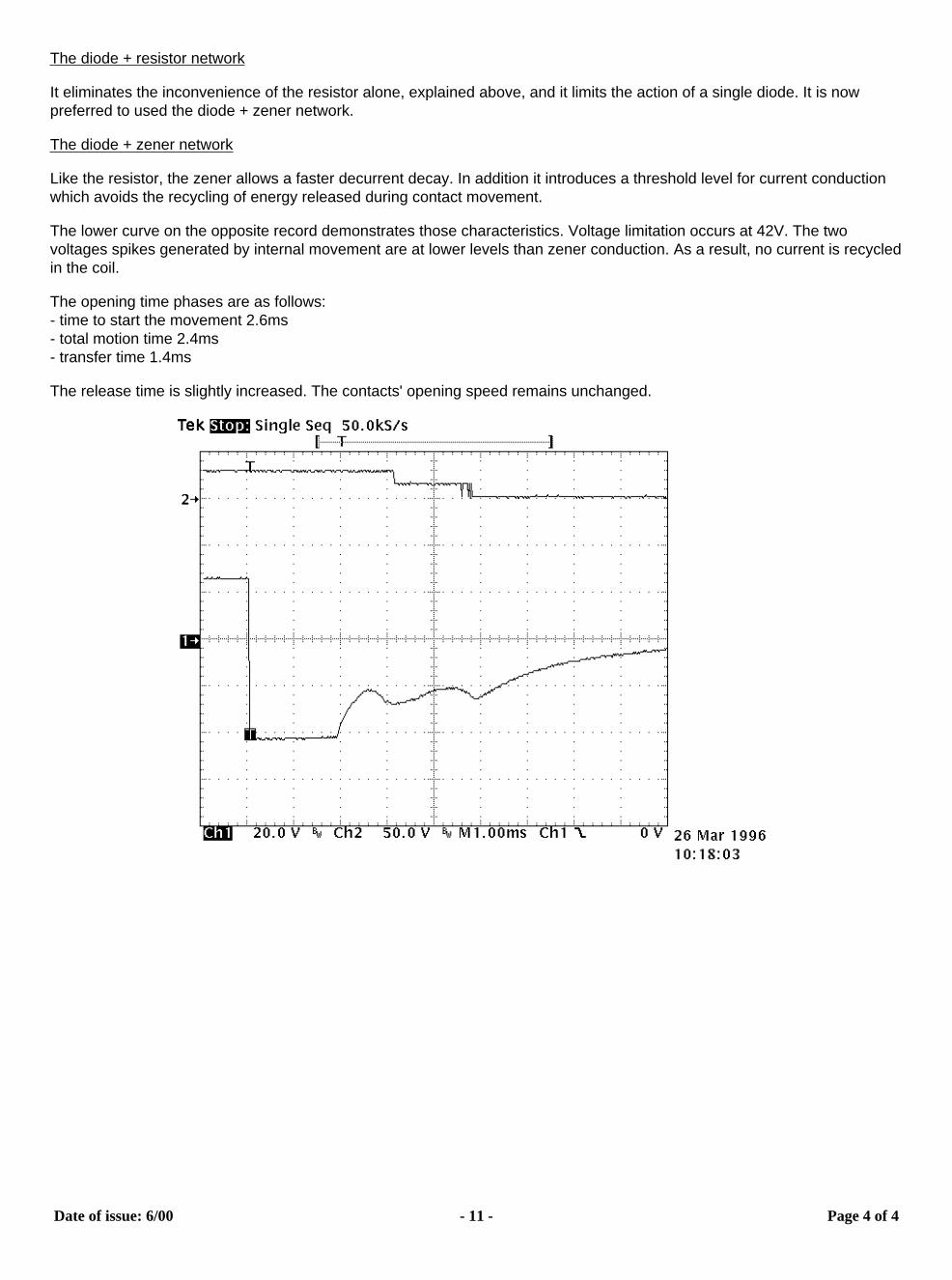
The diode + zener network
Like the resistor, the zener allows a faster decurrent decay. In addition it introduces a threshold level for current conduction which avoids the recycling of energy released during contact movement.
The lower curve on the opposite record demonstrates those characteristics. Voltage limitation occurs at 42V. The two voltages spikes generated by internal movement are at lower levels than zener conduction. As a result, no current is recycled in the coil.
The opening time phases are as follows:- time to start the movement 2.6ms- total motion time 2.4ms- transfer time 1.4ms
The release time is slightly increased. The contacts' opening speed remains unchanged.