79
PRINCIPLES OF FAILURE ANALYSIS Ductile and Brittle Fracture Revised by William T. Becker, Ph.D. Course 0335 Lesson 3

PRINCIPLES OF FAILURE ANALYSIS
Ductile and Brittle Fracture
Revised byWilliam T. Becker, Ph.D.
� Course 0335Lesson 3
Copyright © 2002by
ASM International®
All rights reserved
No part of this lesson may be reproduced, stored in a retrieval system, or transmitted, in any form or by any means,electronic, mechanical, photocopying, recording, or otherwise, without the written permission of the copyrightowner.
Great care is taken in the compilation and production of this lesson, but it should be made clear that NO WAR-RANTIES, EXPRESS OR IMPLIED, INCLUDING, WITHOUT LIMITATION, WARRANTIES OF MER-CHANTABILITY OR FITNESS FOR A PARTICULAR PURPOSE, ARE GIVEN IN CONNECTION WITHTHIS PUBLICATION. Although this information is believed to be accurate by ASM, ASM cannot guarantee thatfavorable results will be obtained from the use of this publication alone. This publication is intended for use bypersons having technical skill, at their sole discretion and risk. Since the conditions of product or material use areoutside of ASM’s control, ASM assumes no liability or obligation in connection with any use of this information.No claim of any kind, whether as to products or information in this publication, and whether or not based on neg-ligence, shall be greater in amount than the purchase price of this product or publication in respect of which dam-ages are claimed. THE REMEDY HEREBY PROVIDED SHALL BE THE EXCLUSIVE AND SOLE REMEDYOF BUYER, AND IN NO EVENT SHALL EITHER PARTY BE LIABLE FOR SPECIAL, INDIRECT ORCONSEQUENTIAL DAMAGES WHETHER OR NOT CAUSED BY OR RESULTING FROM THE NEGLI-GENCE OF SUCH PARTY. As with any material, evaluation of the material under enduse conditions prior tospecification is essential. Therefore, specific testing under actual conditions is recommended.
Nothing contained in this lesson shall be construed as a grant of any right of manufacture, sale, use, or reproduc-tion, in connection with any method, process, apparatus, product, composition, or system, whether or not coveredby letters patent, copyright, or trademark, and nothing contained in this lesson shall be construed as a defenseagainst any alleged infringement of letters patent, copyright, or trademark, or as a defense against liability for suchinfringement.
Comments, criticisms, and suggestions are invited, and should be forwarded to ASM International.
ASM International®
Materials Park, OH 44073-0002www.asminternational.org
Printed in the United States of America

Acknowledgements
Course Revisers
Roy Baggerly, Ph.D., FASMPACCAR Technical Center
William T. Becker, Ph.D.Consultant
Daniel J. BenacBryant-Lee Associates
Dennis McGarryFTI/SEA Consulting
Ronald J. ParringtonIMR Test Labs Incorporated
William R. Warke, Ph.D., FASMRetired Research Metallurgist
Technical Advisor
Gordon W. Powell, FASMOhio State University, Professor Emeritus
Technical Reviewers
Debbie AliyaSusan R. FreemanDavid N. FrenchLarry D. Hanke
William T. KaarlelaArun Kumar, Ph.D.
McIntyre R. Louthan, Jr., Ph.D., FASMKenneth F. Packer, Ph.D., FASM
Robert B. Pond, Jr., Ph.D.James J. Scutti, P.E.
Sharam Sheybany, Ph.D.Roch J. Shipley, P.E.Thomas J. Steigauf
George J. TheusJohn A. Wilkinson
Course Procreator
Donald J. Wulpi, FASMMetallurgical Consultant
Project Coordinators
Kathleen S. DragolichJoanne I. Miller


Principles of Failure Analysis
Ductile and Brittle Fracture
This lesson starts with a discussion of what is meant and implied by thepresence of “ductile” or “brittle” fracture in a broken or cracked part.There is a discussion of both macroscale and microscale fractographicfeatures. Macroscale features typically identify the fracture-initiationsite, crack-propagation direction, and the fracture-surface orientation,correlating with the nominal loading conditions. The microscale featurescorrelate with the microstructure and identify the mechanism(s) bywhich fracture has occurred. Microscale features help identify environ-mental conditions at the time of fracture (e.g., stress-corrosion crack-ing) as well as heat treating imperfections (e.g., tempered martensiteembrittlement).
There is a discussion of pre-existing geometric and microstructuralimperfections that may be defects and therefore cause a component tofail. If an imperfection is a defect, the location of the defect may changethe crack-initiation site from that expected based on the nominal loadingconditions.
Where appropriate, there is also discussion of the importance ofmicrostructural examination to help identify the cause of undesirablecracking. The role of the microstructure in controlling the strength, duc-tility, and toughness of crystalline metallic materials is fundamental toan understanding of the response of a fabricated component to loads anddeformations and ultimately the cause of failure. This lesson presup-poses some exposure to, but not expertise in, the examination and inter-pretation of microstructures. It is assumed that the reader has at leastbeen exposed to the examination and interpretation of microstructuralfeatures. Three important microstructural features affecting mechanicalbehavior are the grain size of the matrix phase, the location of any sec-ond-phase particles, and the presence of entrapped foreign particles(inclusions) in the microstructure. This lesson emphasizes themacroscale and microscale features associated with ductile and brittlefractures.
Upon completion of thislesson you should be able to:� Understand the relationship
between fracture-surfaceorientation and externalloading conditions (axial,torsion, bending)
� Understand how to identifymacroscale features thatidentify the crack-initiationsite and the crack-propagation direction
� Understand how to identifycommon crack-initiationmechanisms
� Understand how to identifythe microscale crack-propagation mechanisms asductile or brittle
� Understand the causes forbrittle fracture in acomponent that when testedas a nominally smooth crosssection tensile specimenshows ductile behavior
� Understand the errors in heattreating that can cause amaterial to fail in a brittlemanner
� Understand the sources ofenvironmentally inducedembrittlement
2 � Ductile and Brittle Fracture
*“Mode” is defined with reference to macroscale loading conditions in ASTM E 399.**Early fractographic studies were often done by the preparation of a replica of the fracturesurface and examination of the replica in the transmission electron microscope (TEM). Theliterature contains many of these fractographs. In such instances, the image is reversed. TheTEM is still of use for the examination of features that exceed the resolution limits of theSEM.
One important issue in characterizing a fracture is whether the fracture isductile or brittle. If there is visible permanent change in shape associatedwith a fractured component, an observer without a materials backgroundwould likely describe the fracture as ductile based on visual evidence ofplastic deformation prior to fracture. A person with a materials back-ground might just as logically examine the microstructure and, if thatexamination showed evidence of plastic deformation, also be inclined todescribe the fracture as ductile. A macroscale fracture surface withoutany visual evidence of plastic deformation is likely to be described as brit-tle by persons with either background. However, microstructural examina-tion of material immediately adjacent to the fracture surface or directexamination of the fracture surface at increased magnification may revealthe presence of local plastic deformation. Similarly, long-life fatigue frac-ture typically occurs at nominal stress levels less than the yield strength sothere is no visible macroscale distortion. This failure condition is oftendescribed as brittle on the macroscale. However, the microscale mecha-nism for fatigue crack initiation and growth in materials showing sometensile ductility is due at least in part to plastic deformation.
Some means of describing the fracture appearance that does not lead topossible confusion based on the scale of observation or background of theobserver as to whether the fracture is ductile or brittle and that results in anaccurate description of the conditions that resulted in fracture is necessary.One such procedure is to describe the macroscopic appearance as ductile,brittle, or ductile plus brittle, based on whether the fracture surface(s) is(are) on a plane of maximum normal stress (brittle) or high shear stress(ductile) and to describe the local scale mechanism of fracture as ductileor brittle based on the microscale appearance and the microscale mecha-nisms that operated to produce the fracture. Fracture surfaces perpendicu-lar to a tensile stress are brittle on the macroscale, whereas fracture sur-faces inclined to a tensile stress (and therefore on planes of high shearstress) are ductile. Adoption of this terminology can prevent misinterpre-tation and disagreements between persons of varying backgrounds.
Additional misinterpretation derives from the use of the term mode,*used in multiple ways in discussions of failure. This lesson uses the termmode in only two ways: (1) to distinguish between micromechanisms offracture (e.g., transgranular versus intergranular, slip versus cleavage)and (2) to distinguish between different macroscale loading conditions(axial, bending, shear).
The determination of the mechanism causing fracture is normallyaccomplished by examination of the fracture surface at high magnifica-tion, usually in the scanning electron microscope (SEM).** Supportingevidence can and should be obtained by examination of the microstruc-ture. Metallographic specimens showing the fracture surface in edge view
Ductile and BrittleFracture
Terminology

Ductile and Brittle Fracture Terminology � 3
reveal the microstructure immediately adjacent to the fracture surface.Microstructural examination is especially useful in identifying the pres-ence of, and the cause for, intergranular fracture.
At the macroscale, a fracture surface may change orientation as a crackpropagates (Figure 1), changing from ductile to brittle or from brittle toductile (more common). For some loading conditions, there may be multi-ple crack-initiation sites on planes of both high normal stress and highshear stress. Microscale examination will show that fracture on planes ofhigh shear stress occurred by a ductile mechanism, but fracture on planesof high normal stress may be either ductile or brittle at the microscale. Thefamiliar cup-and-cone fracture associated with tensile loading (Figure 2)is one case where fracture initiates in the flat portion of the cup(macroscale brittle) and subsequently propagates on a shear plane(macroscale and microscale ductile). Microscale observation, however,shows that fracture in the flat portion of the cup occurs by a ductile mech-anism as does the fracture on the walls of the cup.
Ductile fracture is typically assumed (sometimes incorrectly) to be asso-ciated with high energy absorption and brittle fracture with lower energyabsorption, with high energy absorption being associated with “good”behavior. For the fracture process to require high energy, the material must
(a) (b) (c)
Figure 1. Slant and flat fracture surfaces. (a) Flat and macro brittle(plane strain). (b) Macro brittle changing to macro ductile with loss ofconstraint. (c) Macro brittle changing to general net section yield. Plasticflow on all four shear planes. Source Reference 1, p 129.
Figure 2. (a) Ductile cup-and-cone fracture with necking in a tensile specimen. (b) Brittle frac-ture. Source: Reference 2.

4 � Ductile and Brittle Fracture
be ductile under the loading conditions, have high strength, and havestrain-hardening capacity. The non-heat-treatable wrought aluminumalloys (e.g., 11xx and 3xxx) have moduli of toughness (ultimate tensilestrength � tensile elongation; an approximation of the toughness of thematerial when tested as a smooth-cross-section tensile specimen) of 760to 1930 MPa (110 to 280 ksi), whereas the less ductile aluminum-siliconcasting alloys have moduli of toughness of the order of 1035 to 2070 (150to 300 ksi). Thus, neither group of materials has a very high modulus oftoughness, especially in comparison to a medium-carbon steel in the hot-rolled or quenched-and-tempered condition. The presence of a cracklikedefect in the wrought aluminum alloys does not dramatically lower thetoughness at fracture, and the unmodified aluminum-silicon casting alloysfail in a brittle manner at the macroscale. However, the presence of acracklike defect can dramatically change the work required to cause frac-ture in steels. Steels can be described as notch sensitive, whereas thewrought aluminum alloys are not notch sensitive.
In order for a failure analysis to be successful in determining the cause forfailure, it is usually necessary to perform multiple types of tests on thematerial as described in Lesson 1. Conclusions as to the cause of failureshould be based on the total information available.
Testing at a minimum typically involves examination of the fracturesurface, examination of the macrostructure and microstructure, and someprocedure(s) to evaluate mechanical properties. Hardness testing is oneway to obtain mechanical property information and can be done in con-junction with microstructural examination. Macroscale hardness tests(Rockwell, Brinell) can be used to estimate nominal strength (yield andultimate), but they do not provide information about ductility and tough-ness. Microscale hardness testing can be used to determine possiblechanges in properties near the surface of the component and is especiallyuseful in evaluating surface-treated steel components to check for decar-burization and adequate case depth.
The information obtained from each type of evaluation ideally providespositive information pointing to a single cause for the failure and resultsideally from self-consistent, positive information from all tests. Unfortu-nately, this is not always the case. Sometimes test results from a given pro-cedure are inconclusive or do not point to a single cause for failure. A casein point is the identification of failure due to cyclic loading (fatigue). Ininstances in which cyclic loading is interrupted and then reinitiated, load-ing often leaves characteristic features (known as “beach marks”) visibleat the macroscale on the fracture surface. Secondly, in some materials,cyclic loading also leaves characteristic markings at the microscale on thefracture surface (“fatigue striations”). However, it is possible that onlyone set of markings is present or that neither set of markings is present.Therefore, there may not be any positive fractographic information indi-cating cyclic loading.
The cause for failure has not been identified if conflicting informationis obtained from two different procedures. Common situations involvingthe inability to obtain information or draw conclusions include:
Requirements for aSuccessful Failure
Analysis
Requirements for a Successful Failure Analysis � 5
� Obliteration of microscale features due to oxidation of the fracturesurface
� Abusive handling of the fracture surface after failure
� Improper storage of the fracture surface
� Mechanical damage of the fracture surface during the fracture event
� Results from a specific test does not provide information indicatinga single cause for failure
Macroscale examination will provide information indicating whetherthe fracture is ductile or brittle on the macroscale, and it almost alwaysidentifies the fracture-initiation site. The orientation of the fracture surfacerelative to the component geometry together with the crack-initiation siteprovides information regarding the loading conditions causing failure(Lesson 2). This is extremely important because it may indicate loadingconditions different from that assumed in the design process. Macroscaleexamination often provides information as to whether an observed imper-fection was or was not responsible for degrading the strength or ductility ofthe material. It may identify whether the mechanism of crack propagationchanged during the life of the part. It may or may not distinguish betweenmonotonic and cyclic loading. It may provide information regarding thegrain size of the material. Changes in fracture-surface appearance can insome instances be related to the magnitude of the loads causing fracture.
Microscale examination of the fracture surface will sometimes distin-guish between static loading and cyclic loading. It will identify themicroscale mechanisms causing monotonic-loading fracture. It will some-times identify the action of environmental variables affecting fracture. Itwill identify the fracture as occurring across the grains (transgranular) orbetween the grains (intergranular).
Metallographic examination of the macrostructure will identify thepresence of manufacturing imperfections such as shrinkage cavities andporosity, as well as the presence of proper grain flow during fabrication,the presence of incomplete fusion during welding, the presence of laps orseams, and the nominal volume fraction of resolved inclusions.Macroscale examination will provide information regarding the generalinclusion density and the presence of materials-processing defects such asshrinkage porosity, seams, and laps. Microscale examination will some-times provide information regarding loading and environmental condi-tions at the time of fracture and identify the grain size of the material. Itmay provide information regarding serious errors in heat treatment.Examination of the microstructure adjacent to the fracture surface willdistinguish between transgranular and intergranular fracture.
Evaluation of the microstructure may provide information as towhether the mechanical properties assumed in the design are consistentwith those in the failed component. This is important because it often pro-vides the basis to determine whether the material properties were thoseassumed in the design process and/or whether the properties were degrad-ed by the service conditions.

6 � Ductile and Brittle Fracture
These examination procedures and the results obtained from them arediscussed in more detail throughout this lesson.
In order for the failure analysis to be successful, the root cause must beidentified. Many times, material imperfections are observed in a failedcomponent, but, unless failure can be shown to occur because of theimperfection, the imperfection is not a defect and the cause of failure. Fig-ure 3 (railroad coupler) shows macroscale porosity in a component, butfailure did not initiate at the imperfection. Therefore, this imperfection isnot a defect.
One common thread that runs through many failure analyses is theabsence of any (or very much) visible macroscale plastic deformationassociated with a fracture surface when the same material shows extensiveplastic deformation when tested as a smooth tensile specimen. There aremultiple causes for this behavior.
Macroscale brittle fracture may occur because:
� The loading conditions do not permit the material to flow plastically.
� The state of stress (large triaxial tensile stresses) in the materialdoes not permit plastic deformation in a sufficiently large volume ofmaterial that it is visible at the macroscale.
� The service environment embrittles the material.
� The material is inherently brittle (perhaps due to faulty heat treating).
Brittle fracture can occur in service without prior plastic deformation atthe macroscale (although the material may have been plastically deformedduring fabrication) so that there is no warning that fracture is imminent.This may result in catastrophic failure. Ductile tensile overload failures
Brittle Fracture in a“Ductile” Material
Figure 3. Fracture surface of a railroad coupler. Fracture initiated atelliptically shaped fatigue crack (dark region). Radial pattern andchevrons point back to the crack-initiation site. Note that the porosityimperfection did not initiate the crack.

Brittle Fracture in a “Ductile” Material � 7
typically provide some warning that failure is imminent. Proper mainte-nance procedures will then cause replacement of the part so that fracture isaverted. For example, excessive deflection of a shaft can cause accelerat-ed bearing wear that is typically indicated by noisy operation. Permanentset in a spring will cause its replacement. However, overload bucklingfailures due to elastic stress may provide little warning.
Triaxial tensile stresses inhibit plastic deformation and also elevate thestress at which plastic deformation begins. If the stress to cause plasticdeformation is increased sufficiently, it can exceed the stress required tocause fracture. Therefore, it is necessary to understand how triaxial tensilestresses can be developed in a component.
Figure 4(a) shows an element of material subjected to a single tensile load.If the load causes the yield strength to be exceeded, plastic deformationoccurs. The material becomes longer in the direction of the load and con-tracts in the two directions perpendicular to the load. In Figure 4(b), theblock of material is subjected to two tensile loads. Plastic deformation isstill possible. The material now extends in two directions and contracts inthe third unloaded direction. However, if three tensile loads, all of thesame magnitude, are applied to the material, the material cannot deformplastically if the volume remains constant; that is, the sum of the plasticstrains must be zero (Figure 4c). The loading conditions in Figures 4(a)and (b) are described as plane stress (because all of the load directions liein a common plane).
A general state of stress acting on the element has two parts: a hydro-static component and a nonhydrostatic component. The hydrostatic com-ponent is defined as the mean value of the three normal stresses. The stateof stress in Figure 4(c) is then pure hydrostatic loading.
Consider now a body containing a cracklike defect (Figure 5). There isstress concentration behind the notch, and, because material wants to
Triaxial Stress andDuctility
��� ��� ���
������
������
Figure 4. Change in shape of an element of material subjected to loads. (a) Uniaxialloading. Plastic extension parallel to the load, contraction in two directions perpen-dicular to the load. (b) Biaxial tension gives plastic extension in two directions paral-lel to the applied load and contraction in the third unloaded direction. (c) Pure hydro-static loading. If all three loads have the same magnitude, the material cannotplastically deform.

8 � Ductile and Brittle Fracture
Applied loadSide view
Crack length, a
Thickness, B
Plane of crack
No stress onthis surface
Top view on plane of crack. Stress concentration behind the notch with Poisson's contraction
would create shape shown. Unloaded area of notch prevents this contraction and creates the
internal stresses acting normal to the applied load as shown.
Figure 5. Constraint in an axially loaded member that contains a crack-like defect. As the notch severity increases (thicker material, longer crack,sharper crack tip radius), the stress at fracture increases but the strain atfracture decreases.
contract perpendicular to the stress in the y direction, the material behindthe notch would like to assume the geometry shown. However, there areno loads applied to the surface of the crack, so whatever state of stressexists inside the body, the material adjacent to the notch has no tendencyto contract. The material in this region therefore exerts a restraining forceon the stressed material.
The actual behavior of the material when stressed to fracture dependson the size of the unloaded area (section thickness and crack length). Fig-ure 6 shows that as the section thickness or the crack length increases, thestress at yield is increased, and the tensile elongation at fracture isreduced. A similar effect occurs as the radius of the crack tip is reduced.Measurement of the lateral contraction (z direction) of these specimens inFigure 5 shows that as the size of the unloaded (notched) area is increased,
Extension
Load
Smoothspecimen
Increasing constraint: Increasing section thickness, crack length Decreasing notch tip radius
Figure 6. Tensile stress-strain curves for a specimen containing a notchof increasing severity (increase in constraint). Note that the yield strengthand tensile strength increase and the fracture strain decreases as notchseverity increases.

Brittle Fracture in a “Ductile” Material � 9
*Note: three standard symbols are used for the geometric correction factor “Q,” “Y,” and“[f(a /W )]” that are tabulated in the literature. Q is used for partial thickness surface andembedded flaws. Both Y and f(a /W ) are used for other geometries. However, some care isrequired in using the tables to determine whether the p in Equation 1 is or is not included in Y.
the lateral contraction becomes very small. One can then say that the spec-imen failed in plane-strain loading conditions. That is, because there isminimal lateral contraction, the strain directions lie in a plane. The loss oflateral contraction (plastic strain) results in constraint in the specimen.
Although there is minimal strain in the thickness direction, there is astress in that direction. This tensile stress must exist to prevent the materi-al from contracting. Similarly, no force was applied in the x direction (per-pendicular to the crack front). If the specimen does not contract in the xdirection due to the load in the y direction, there must again be an internalstress in the x direction to prevent contraction. Consequently a largehydrostatic stress can exist in the interior of the specimen behind thenotch if the thickness or crack length is large. This large hydrostatic stressthen causes the material to behave in a brittle manner at the macroscale.
The change from macroscale ductile (plane-stress) to brittle (plane-strain) behavior can be predicted and quantified based on the stress-intensity factor, K. The stress-intensity factor is given as:
K � S �pa� [Y] (Equation 1)
where S is the nominal stress on the specimen, a is the crack length, and Y*is a geometry correction factor that is tabulated in handbooks similar to thetabulation of stress-concentration factors. For example, if the ratio of thecrack length to the specimen width is less than about 0.13, the correctionfactor Y can be taken as 1.12 for a single-edge notch in a plate component.For a through-thickness-center-line crack in the plate, Y can be taken asunity for a crack length-to-specimen width ratio less than 0.4. Correctionfactors are given for common geometries in many books on mechanicalbehavior. The most complete reference is Tada et al. (Reference 3).
If K at failure is calculated from the loading data and plotted againsteither the initial crack length, or the section thickness, Figure 7 results.
Increasing shearlip area
Plane strain, macrobrittle, no shear lips
K
K l c
a, B
Figure 7. Variation in stress intensity at fracture versus section thickness(B) or crack length (a). At large crack length or section thickness K atfracture becomes independent of these variables and becomes a materialproperty, the plane-strain fracture toughness (KIc).

10 � Ductile and Brittle Fracture
The figure shows that K at fracture becomes constant after some minimumthickness or crack length. Measurements on the broken specimen showthat K becomes constant when the lateral contraction behind the notchreaches a minimum value, so that the deformation becomes plane strain.This critical value of K at fracture is known as the plane-strain fracturetoughness (KIc). KIc is a material property and depends on alloy composi-tion and microstructure.
Toughness measured in this way predicts behavior of the material whenit contains a cracklike defect, whereas the modulus of toughness (ultimatetensile strength � tensile elongation) is a measure of toughness when thecross section does not contain a stress concentrator. Significantly, manymaterials are notch sensitive so that there is a significant difference inenergy absorbed at fracture between notched and unnotched specimens.
If the geometry of the crack and component creates plane-strain load-ing conditions or if the material is inherently brittle, the value of the stresscausing fracture can be calculated if KIc and the size of the cracklikeimperfection are known:
S � �Y �
KIc
pa�� (Equation 2)
This is important because it permits evaluation of a failed component todetermine if it was loaded above the design stress.
Alternatively, if the magnitude of the service load is known, it is possi-ble to determine whether the material was improperly processed and, as aresult, had a fracture toughness less than that assumed in the design.
Kcrit � SY�pa� (Equation 3)
If fracture occurs for Kcrit less than KIc, the mechanical properties are notthose assumed in the design. That is, the microstructure (including inclu-sion count) and/or alloy composition is different from that assumed.
Finally, if the loading conditions and KIc are known, a critical cracklength can be calculated and used in conjunction with nondestructiveevaluation to determine if a component contains imperfections thatexceed the critical crack length.
acrit � �S
(K2Y
Ic2
)
�
2
� (Equation 4)
If the measured value of the crack length on the fracture surface is lessthan acrit as calculated from the material properties and loading conditions,either the applied loads or the fracture toughness is different from thatassumed in the design. Critical crack lengths are discussed in more detaillater in this lesson.
In the case where the cracklike defect goes completely through the sec-tion thickness, it is possible to estimate the section thickness and/or

Brittle Fracture in a “Ductile” Material � 11
required crack length to cause macroscale brittle fracture. Plane-strain(macroscale brittle) fracture will occur if:
a,B � 2.5��K
SIc��
2
(Equation 5)
where a is the crack length, B is the section thickness, S is the nominalstress, and KIc is the plane-strain fracture toughness. This criterion is con-servative in that plane strain will always be met when these conditions aresatisfied but may be met for a smaller thickness.
Materials having a body-centered-cubic (bcc) arrangement of atoms(including steels) and some materials having a hexagonal-close-packed(hcp) lattice show a typical S-shaped curve of toughness versus tempera-ture, whereas materials having a face-centered-cubic (fcc) lattice show agradual decrease in toughness with decreasing temperature (Figure 8). Val-ues of interest on the curve include the maximum toughness on the uppershelf, the temperature at which the toughness curve begins to rise dramati-cally, and the minimum toughness at low temperature. Before 1960 (and tosome extent still today), the most common way of measuring fracturetoughness was the use of pendulum impact tests such as the Charpy andIzod tests (discussed later in this lesson). These tests are still useful, espe-cially to evaluate the change in toughness with changes in microstructure orcomposition. However, the Charpy and Izod tests do not discriminate dif-ferences in toughness below the toe of the curve and therefore do not dis-criminate between different sizes of imperfections. Additionally, it is notpossible to extract a value of the stress at which fracture occurred in thesependulum impact tests. Therefore, it is not possible using pendulum impactdata to determine whether a component was loaded above the design stressor to determine whether an imperfection in the material was of sufficientsize or in a critical location to become a defect. The list of possible imper-fections is quite lengthy, but it includes geometric imperfections such assurface nicks and gouges, metallurgical imperfections such as lack of pene-tration in a weldment, shrinkage porosity in a casting, and quench cracks.There is a discussion of crack-initiation sites in a later section of this lesson.
Thermal Effects
Temperature
Toug
hnes
s
B
A
Figure 8. Variation in fracture toughness with temperature for (A) bccmaterials (including steels) and (B) fcc materials (including aluminumalloys and austenitic stainless steel).

12 � Ductile and Brittle Fracture
The fracture mechanics approach can often permit determination of criti-cal stresses and/or crack lengths.
The curve in Figure 9 shows the behavior of three different steels orthe same steel processed in three different ways. Correct mechanical/thermal processing usually does not result in room temperature corre-sponding to upper-shelf toughness (curve A). An exception is the 5 and9% Ni ferritic steels. Curve B is typical of many properly processedmaterials, whereas curve C would be typical of an improper materialselection or improper microstructure. Improper heat treating can result inshifting the toughness curve from A to B or A to C so that the fracturetoughness at room temperature is low. As carbon content increases, thetrend is to shift the curve from A or B to C and also to decrease the upper-shelf toughness.
The fracture toughness of steels varies widely depending on many com-position and microstructural variables. However, the general trend is forfracture toughness to decrease as the yield strength increases (Figure10). Qualitatively, for a medium-carbon steel (heat treatable), the frac-ture toughness of tempered martensitic microstructures is higher thanthat of bainitic microstructures, which in turn is higher than that ofpearlitic microstructures. However, improper tempering of martensiticmicrostructures may reduce fracture toughness to very low values. Thetoughness of hot-rolled pearlitic microstructures can be improved with anormalizing heat treatment (grain-size reduction) or a stress-reliefanneal. Most interest in measuring KIc has been for higher-strength steelsused in critical design situations, whereas steels for less-critical applica-tions are more commonly evaluated via Charpy impact testing. Examina-tion of data in Reference 4 shows that the room-temperature value of KIcseldom exceeds 130 MPa�m� (120 ksi�in.�), and, more importantly, the square of the ratio of fracture toughness to yield strength seldom ex-ceeds 2 for the materials shown in Figure 11. However, there are excep-tions and KIc for lower-carbon (0.2% C) pearlitic steels can exceed 220MPa�m� (200 ksi�in.�). If the squared ratio of toughness to yield
Data Trends for Steels
RTTemperature
A B C
K I c
Figure 9. Variation in fracture toughness for three different steels or thesame steel with three different microstructures. RT, room temperature. Seetext for discussion.

Brittle Fracture in a “Ductile” Material � 13
20
40
60
80
100
120
150
18% Ni maraging
175 200 225
Yield strength, ksi
250 275 300 325
Fra
ctur
e to
ughn
ess,
(K
Ic),
ksi
√ in
.
D6AC
300M
4340
H-11
4340 (Mod Si)
Figure 10. Typical variation in KIc with yield strength. Source: Reference 4.
3.0
2.0
Tests conducted +80 °FVM —vacuum meltedAM—air meltedWestinghouse data
HY-130 AM
1.0
00.10 0.2 0.3 0.4 0.5 0.6 0.7
CVN/σv, ft • lb/ksi
A517-F(AM)Ni-Cr-Mo-VFD 1196
Ni-Cr-Mo-VMH 980
12Ni VM12Ni VM
(KIc
/σy)
2 , in
.
(KIc/σy) = [CVN Ð (σy/20)] ¥ 5/σy
18Ni (190) VM
18Ni (180) VM9-4-25 VM
4147 AM12Ni AM
4130 AM18Ni (180) AM
18Ni (250) VM
Figure 11. Correlation between (fracture toughness/yield strength)2 andCharpy impact strength on the upper shelf. Source: Reference 4.

14 � Ductile and Brittle Fracture
strength is 2, Equation 5 indicates that the critical crack length or sectionthickness at room temperature is:
a,B � 2.5(2) � 5 in. � 125 mm (Equation 6)
Thus, brittle fracture is not expected except for large sections or longcracks. At high strength levels, the required section thickness or cracklength to obtain brittle fracture can be quite small, even at room tempera-ture. For example, for SAE 4340 heat treated to 51 HRC, reference val-ues of the yield strength and toughness are 1517 MPa (220 ksi) and 57 MPa�m� (50 ksi�in.�) so that the critical crack or section thickness is:
a,B � 2.5��15
5
7
17��
2
� 0.0035 m � 0.139 in. (Equation 7)
At high strength levels or after improper heat treatment of steels, thecritical crack length can be as small as 50 �m (2 mils). Because the criti-cal crack length can be so small, it is not surprising that brittle fracture canbe initiated by small manufacturing imperfections (a too-sharp keyway orfillet, threads, and splines), scratches, and gouges due to improper han-dling or a poor weld bead contour.
The ductile-brittle transition temperature (DBTT) associated with thebcc lattice is sensitive to the deoxidation practice used as well as to thenominal composition and microstructure, including grain size. For hot-rolled pearlitic steels, a reduction in grain size can decrease the DBTT dra-matically, with changes of 26 to 56 °C (50 to 100 °F) possible. Rimming-grade steels have a higher DBTT than an alloy of the same compositionthat has been killed (aluminum deoxidized). The lowest toughness is asso-ciated with untempered martensite. Properly tempered, a quenched-and-tempered martensitic microstructure optimizes the combination of yieldstrength and fracture toughness and provides the lowest DBTT tempera-ture. However, it is possible to temper a steel improperly, resulting in adegradation of toughness and an increase in the DBTT as discussed in thesection on heat treating imperfections later in this lesson. Upper bainite haspoorer toughness and a higher DBTT than lower bainite.
The most common technique to strengthen traditional steels involves anincrease in the carbon content. Unfortunately, this approach also raises theDBTT and lowers the upper-shelf toughness. Sulfur and phosphorus aretwo trace-level impurities that also raise the DBTT. Most alloying ele-ments raise the DBTT (less dramatically than phosphorus and sulfur),exceptions being nickel and manganese. Nickel additions up to about 8%are effective in lowering the DBTT (23xx and 25xx steels).
Manganese has a beneficial effect because it removes sulfur from solidsolution as manganese sulfide (MnS). It is common to control the manganese-to-carbon ratio from about 3-to-1 to 7-to-1 for this purpose.Higher manganese contents are not used because of the lowering of themartensite start temperature and associated heat treating problems due toretained austenite. Additionally, as discussed later, a loss of toughness andan increase in the DBTT is associated with the presence of trace levels of

Brittle Fracture in a “Ductile” Material � 15
Figure 12. Microscale segregation (banding) in steel results inmicrostructural bands of pearlite and ferrite steel after slow cooling fromabove the upper critical temperature. Banding is minimized with fastercooling rates. Banding leads to variation in mechanical properties withspecimen orientation. Source: Reference 5.
Aluminum Alloys
arsenic, antimony, tin, and phosphorus in conjunction with manganese inquenched-and-tempered steels. Steels having less than 0.5% Mn are lesssusceptible to this latter type of embrittlement.
For wrought, hardenable, high-strength aluminum alloys (2xxx, 7xxx), thetoughness (KIc)-to-yield strength ratio varies from about 1⁄3 to 1⁄2, so therequired section thickness for plane-strain fracture is about 7 to 15 mm(0.28 to 0.6 in.). Non-heat-treatable, wrought aluminum alloys (1xxx,3xxx, 5xxx) as used commercially do not fail in plane strain and have highfracture toughness. However, the aluminum-silicon casting alloys (heattreatable and non-heat treatable) do not have high fracture toughness.Toughness is improved by modifying these alloys to change the morphol-ogy of the silicon phase from platelike to spheroidal, but KIc does not typ-ically exceed 11 to 16.5 MPa�m� (10 to 15 ksi�in.�). Optimal toughnessin the hardening alloys is obtained by overaging (e.g., the T73 temper).
Primary metalworking practice—rolling, extrusion, forging, and soforth—typically results in a nonhomogeneous microstructure in whichmicroscale bands of varying composition are parallel to the direction ofgreatest flow (banding). Additionally, ductile inclusions have high aspectratios after forming, and there may be strings of oxide “beads” in the flowdirection. Bands of varying composition may result in a variation ofmicrostructural constituents in the bands (Figure 12). The net effect is tocause considerable variation in ductility and fracture toughness (andfatigue crack propagation rates) with loading direction. This directionalityhas received considerable attention in the steel industry and has resulted incalcium ladle additions to minimize the directionality. Ladle additions ofcalcium to electric furnace steel reduce the number of stringer-type MnSand oxide inclusions, and such additions also permit “shape control”resulting in spheroidal inclusions (complex sulfide-aluminates). For suffi-ciently thick material, reduction in area obtained from a tensile specimen
Directionality ofProperties

16 � Ductile and Brittle Fracture
taken parallel to the thickness direction can be compared to that from aspecimen taken parallel to the rolling direction or transverse direction toevaluate the degree of anisotropy. Alternatively, Charpy or compact ten-sion specimens can be used. For conventional melt practice, the differencein upper-shelf Charpy energy for a crack propagating in the rolling direc-tion versus a crack propagating in the transverse direction can be as muchas a factor of 5 (Reference 6).
If the orientation of the fracture surface of plate specimens of increasingthickness is considered, it is observed that specimens having a short crackor small section thickness fail on a plane of maximum shear stress (Figure13a) (macroscale ductile). Very thick specimens or specimens having along initial flaw fail on a plane normal to the applied load (macroscalebrittle) (Figure 13c). Intermediate values of section thickness produce amultiple-orientation fracture surface in which the interior region is per-pendicular to the load, but the regions closer to the edge fail on a shearplane (Figure 13b). The slant fracture regions near the surface are termedshear lips. The presence of shear lips is an important macroscale fracto-graphic feature because it identifies the direction of crack propagation.The crack runs parallel to the length of the shear lips. That is, a crackpropagating perpendicular to the applied load toward a free surface createsa shear lip that has length and width. The direction of crack propagation inthis case is perpendicular to the length and parallel to the width of theshear lip. Additionally, presence of shear lips indicates incomplete con-straint, so that the stress intensity at fracture is greater than KIc. As dis-cussed below, there are additional fractographic features that identify thespecific site of crack initiation.
When sections are small enough that the local stress field at an imper-fection extends to the outer surface of the material, the crack plane maydiverge from its initial orientation. Figure 14 shows the effect of inadequateheight of the specimen so that net section yield occurs. A similar curvatureof the crack plane is obtained for an inadequate component width.
Change in Fracture-Surface Orientation
(c)(b)(a)
P
B
B
a
Figure 13. Change in fracture-surface orientation as the section thick-ness B increases. (a) Thin material. Fracture on a shear plane. (b) Partialconstraint. Fracture on plane normal to load in center with shear lips pre-sent. (c) Fully constrained fracture on plane of maximum normal stress.

Brittle Fracture in a “Ductile” Material � 17
Figure 14. When the specimen has inadequate height (or width) so thatthe volume of material in which the stress distribution predicted by thestress-intensity factor extends to the surface of the specimen, the crackplane curves as shown. Source: Reference 7, p 199.
Two closely related macroscale fractographic features that identify thelocation of crack initiation are radial marks and chevrons. These featuresare created by microscale brittle fracture (cleavage). A third feature thatalso indicates crack growth direction can be described as a “ridged pat-tern,” which is formed by a ductile process. However, in addition the term“ridged pattern” is used to describe surface waviness that is created bymicrostructural features (i.e., alternating plates of cementite and ferrite inpearlite. In some cases, the term “ridge pattern” is used to genericallydescribe any of these patterns. Figure 15 shows a ridged pattern created bya ductile process (and should not be described as a radial pattern). Figure16 shows a set of chevrons. The fanlike array of radial marks points backto the initiation site and the “V,” or arrowhead, of the chevrons also pointsback to the initiation site.
The courseness and definition of the ridge pattern depends on the gen-eral strength level of the material and the test temperature. It has been pro-posed that the pattern is developed where there is “rapid” crack propaga-tion (Reference 50). Compare the ridge pattern shown in Figures 15, 17,and 18. The coarse ridged pattern in Figure 15, 18(b), and 18(c) is createdby plastic flow, where as the fine ridged pattern in Figure 18(a) is created
Radial Marks andChevrons

18 � Ductile and Brittle Fracture
Figure 16. Chevrons. As a crack propagates into the material under condi-tions of limited ductility, radial marks change into chevrons. The “V” of thechevron points back to the crack-initiation site. Source: Reference 8, p 91.
Figure 15. A ridge pattern is visible on the fracture surface of a material thatshows limited ductility during fracture. The marks point back to the crack-initiationsite. Source: Reference 8, p 96.
by cleavage. When cracks propagate faster in the interior of a section thanat the surface by a brittle mechanism, the result is chevrons (Figure 16).When crack propagation is faster at the surface than at the interior, onlyone side of the “V” is present, and the feature is the (a) set of radial lines.Ridge patterns formed by ductile processes are visible with the naked eye.Radial patterns (brittle) can usually be seen with the naked eye, but some-times a 5� or 10� hand lens is required.
Figure 18 shows the fracture surface of a set of steel tensile specimensbroken at successively higher temperatures. At the lowest temperature(below the DBTT), fracture is predominantly by cleavage creating a fine
Brittle Fracture in a “Ductile” Material � 19
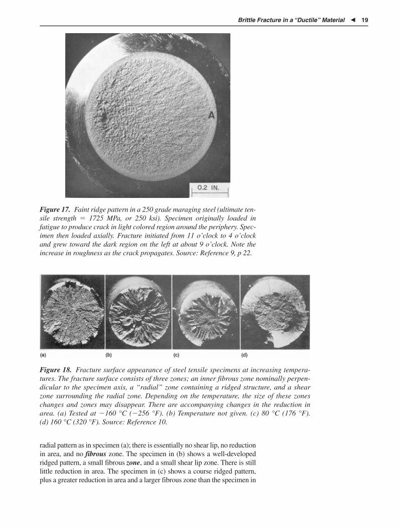
Figure 17. Faint ridge pattern in a 250 grade maraging steel (ultimate ten-sile strength � 1725 MPa, or 250 ksi). Specimen originally loaded infatigue to produce crack in light colored region around the periphery. Spec-imen then loaded axially. Fracture initiated from 11 o’clock to 4 o’clockand grew toward the dark region on the left at about 9 o’clock. Note theincrease in roughness as the crack propagates. Source: Reference 9, p 22.
Figure 18. Fracture surface appearance of steel tensile specimens at increasing tempera-tures. The fracture surface consists of three zones; an inner fibrous zone nominally perpen-dicular to the specimen axis, a “radial” zone containing a ridged structure, and a shearzone surrounding the radial zone. Depending on the temperature, the size of these zoneschanges and zones may disappear. There are accompanying changes in the reduction inarea. (a) Tested at �160 °C (�256 °F). (b) Temperature not given. (c) 80 °C (176 °F). (d) 160 °C (320 °F). Source: Reference 10.
radial pattern as in specimen (a); there is essentially no shear lip, no reductionin area, and no fibrous zone. The specimen in (b) shows a well-developedridged pattern, a small fibrous zone, and a small shear lip zone. There is stilllittle reduction in area. The specimen in (c) shows a course ridged pattern,plus a greater reduction in area and a larger fibrous zone than the specimen in

20 � Ductile and Brittle Fracture
(b). Finally, in specimen (d) the ridge pattern has disappeared, the reductionin area is large, and the fracture surface consists of a central fibrous region(largest of the four specimens) and a large shear zone.
Identification of the fracture-initiation site is an important step in deter-mining cause for failure, and documentation of the fracture-initiation siteis important in preparation of a report. Therefore, it is important that pho-tographs show the presence of these marks. They may not be visible ifincorrect lighting is used. Qualitatively, the smoother the fracture surface,the more oblique the lighting on the specimen must be to create the neces-sary relief contrast. One procedure that often works well is to use one lightperpendicular to the specimen together with a high-intensity lamp at anoblique angle. By moving the high-intensity light around the specimen, anoptimal location to best bring out the ridge pattern can be obtained. Morethan one lighting arrangement may be necessary to identify clearly all ofthe information visible on the fracture surface. It is critical to have posi-tive, nonconfusing evidence to support stated conclusions.
The location of the crack-initiation site sometimes provides informa-tion as to whether failure occurred because of loading above the valuesused in design or whether the material contained imperfections thatcaused the material to fail at or below the design loads. Constraint devel-ops first at midthickness of an edge or center-notched member for axialand bending loading. Consequently, in a specimen containing a similarcracklike defect, the crack-initiation site is located near the centerline inopening-mode loading. If the fractured component shows crack initiationvery close to one side, the implication is that some other condition movedthe crack-initiation site away from the location predicted by macroscalestress analysis. This could be a second local stress concentrator superim-posed on the macroscale, cracklike defect or could be a region containinga microstructural imperfection. Alternatively, the loading conditions maynot have been simple mode I.
Several tests have been developed to determine the effect of temperatureon fracture toughness. They include the Charpy (three-point bending) andIzod (cantilever bending) pendulum-impact tests, the slow-bend Charpytest, the drop-weight test (which defines the nil-ductility temperature),and the Robertson test. Each test has advantages and disadvantages in cor-relations with service performance including section size effects, difficul-ty and expense of specimen preparation, testing, and so forth. This lessondiscusses only the Charpy test, but discussions of the other tests are avail-able in the literature.
The pendulum-impact test has been used for many years to evaluatethe toughness of materials, especially steels. In this test, a notched steelspecimen is impacted by a falling weight. Either absorbed energy, per-cent shear fracture, or lateral expansion are measured as a function ofthe test temperature. If impact energy is measured, two data points ofinterest are the temperature at which the toughness first starts to rapidlyincrease (often indexed at 13.5 J, or 10 ft � lbf) and the toughness on theupper shelf. Unfortunately, the ability of the test to distinguish differ-ences in behavior due to composition and/or microstructures at low tem-
Transition TemperatureApproaches to Fracture
Toughness

Brittle Fracture in a “Ductile” Material � 21
Loading Rate
peratures (i.e., at low toughness), is poor. The curves of all steels show1.35 to 6.78 J (1 to 5 ft � lbf) of absorbed energy at low temperatures.However, the 13.5 J (10 ft � lbf) (or sometimes 20.3 J, or 15 ft � lbf) tran-sition temperature and the upper-shelf toughness are sensitive tomicrostructure and composition. Consequently, this test is a standard wayto evaluate differences in toughness for these variables.
It is difficult to use data from the Charpy and Izod tests to predict thefracture stress or fracture toughness of a failed component having a differ-ent geometry. The loading rate in the test is high relative to the loading ratein many service conditions, and the crack geometry relative to the sectionsize is often significantly different from that of the failed component. Fur-thermore, there is no way to extract from the data the stress at the time offracture. However, the stress-intensity factor shows the same variation withtest temperature as the pendulum-impact data, and results from this test doprovide a value of stress at the time of fracture if the fracture occurred underessentially plane-strain conditions. (Values of the stress at fracture whenplane-strain conditions are not met can also be obtained, but are beyond thescope of this lesson.) Also, stress-intensity factor data do not lose their sen-sitivity at low temperatures. There are empirical correlations in the literatureto convert Charpy data to fracture toughness data (KIc) for structural gradesteels. The collected results of that work and other correlations are availablein Roberts and Newton (Reference 11) and in Hertzberg (Reference 16).
Another variable of importance in determining toughness of a material isthe loading rate. An increased loading rate raises the yield strength of thematerial and also increases the DBTT (Figure 19). The shift in DBTTtends to decrease as the yield strength of the steel increases.
Figure 19. Change in fracture toughness with loading rate for an A572 steel.b is the cutoff for plane-strain fracture. Source: Reference 12, p 118.

22 � Ductile and Brittle Fracture
Figure 20. The differences in. surface topology created by differences inatom shear for (a) slip and (b) twinning. Source: Reference 13, p 205.
The preceding discussion shows the importance of loading conditions,specimen geometry, and test temperature in causing a change frommacroscale ductile to brittle fracture. If cracklike imperfections are pre-sent in the material, geometric constraint can develop high triaxial stress-es near the defect and result in macro brittle fracture. Cracklike imperfec-tions may be geometric in nature (changes in cross section resulting inregions of high stress concentration, nicks, and gouges in the part). Theymay also be laps and seams that formed during prior plastic forming, orthey may be metallurgical in nature such as quench cracks.
Two other variables of importance are the service temperature and theloading rate. Larger sections and higher loading rates increase the temper-ature at which the ductile-brittle fracture transition occurs. As discussedpreviously, two other important variables in controlling the toughness andthe DBTT are composition (especially nickel, manganese, carbon, sulfur,phosphorus) and microstructure.
Single crystals of metallic materials may deform plastically by twoprocesses: slip and deformation (mechanical) twinning. They may frac-ture due to continued plastic deformation due to slip or fracture in a brit-tle way due to an elastic stress by cleavage. Slip and deformation twin-ning are shear processes and occur on specific crystallographic planes inspecific directions when a shear stress reaches a critical value (Figure 20).Cleavage also occurs on a specific crystallographic plane, but occurswhen a sufficiently high normal stress is obtained on the cleavage plane
Figure 21. Cleavage cracking in a molybdenum single crystal at roomtemperature. Source: Reference 13, p 438.
Summary
MicroscaleDeformation and
FractureMechanisms

Microscale Deformation and Fracture Mechanisms � 23
*The very small amount of dislocation motion, and therefore, plastic deformation, that mustoccur to grow a cleavage-crack nucleus to critical length is neglected here.
(Figure 21). Cleavage in the bcc lattice usually occurs on the cube plane,that is, (001), and, in the case of the hcp lattice, cleavage occurs on thebasal plane, that is, (0001). However, other cleavage planes have beenreported for both lattices. Slip usually occurs on planes of high packingdensity and small interplanar spacing so as to minimize the shear strainrequired for the process. Similarly, deformation twinning occurs onplanes that minimize the shear strain in the process. Cleavage crackingmay be initiated due to the strains created by mechanical twinning,* andthe intersection of two twins inside a grain may become a crack-initiationsite. Polycrystalline materials deform and fracture by these same process-es, but may also fracture in the grain boundaries.
The term “twin” refers to a particular atomic arrangement and stackingsequence of atoms. This arrangement may be obtained by either mechani-cal (deformation twins) or thermal processing (annealing or growthtwins). Growth twins are common in materials having a fcc lattice exceptaluminum and its alloys. They do not form in bcc or hcp lattices. Figure 22shows mechanical twining in a 26Cr-1Mo ferritic stainless steel that wasexplosively loaded (expansion forming). Note that these deformationtwins have the shape of a lens. This is in contrast to annealing or growthtwins that have parallel straight sides (Figure 23a).
There are three common arrangements of atom sites in metallic materi-als—fcc, bcc, and hcp (Figure 24), and, in metallic materials, there is usual-ly only one atom per lattice site. Metals and alloys that have a fcc lattice(aluminum, copper, nickel, gold, silver, and their alloys, austenitic stainlesssteels) deform easily by slip but do not mechanically twin (Figure 25)except possibly under extreme conditions of impact loading rates at lowtemperature, nor do they fracture by cleavage (Figure 8). Therefore, brittlefracture by cleavage in a benign environment is not a possible fracture
Figure 22. Mechanical twins formed in a 26Cr-1Mo ferritic stainlesssteel. Magnification: 750�. Etchant: 10% oxalic acid. Illumination:Nomarski differential interference contrast. Source: Reference 14.

24 � Ductile and Brittle Fracture
Figure 23. (a) Annealing twins in 70–30 cartridge brass revealed by contrast etching. Annealing twinsare parallel sided and generally extend completely across the grain. (b) Same material after annealingand then cold rolling 20%. Note the curvature in some of the twins. Courtesy of Gene Stansbury.
Figure 24. The three most common crystal structures of metallic materials. (a) Face-centered cubic(fcc). (b) Body-centered cubic (bcc). (c) Hexagonal close packed (hcp).
fcc
Growth twinsexcept in Al
Increasing ease of cleavage withdecreased temperature or increased loading rate
Increasing ease of deformation twinning withdecreased temperature or increased loading rate
bcc
No growth twins No growth twins
hcp
Figure 25. Prevalence of growth twins, deformation twins, and cleavagewith crystal lattice, temperature, and loading rate.

Microscale Deformation and Fracture Mechanisms � 25
*Some researchers have argued that cleavage does occur in highly nitrogenated austeniticstainless steels and in austenitic stainless steels subjected to SCC conditions.
mechanism in the matrix of these alloys.* Metals and alloys having a hcplattice (zinc, cadmium, magnesium, titanium, zirconium, beryllium, andtheir alloys) deform easily by slip, but also mechanically twin easily.Additionally, they may fracture by cleavage at relatively low loading ratesand at moderate fractions of the melting point (e.g., room temperature).(Some of these materials deform so easily by deformation twinning thatartifact twins can be introduced in metallographic specimens by the pol-ishing pressure.) Metals and alloys having a bcc lattice (iron, niobium,chromium, molybdenum, tantalum, tungsten, and their alloys) deform byslip, deformation twinning at higher strain rates and/or lower temperaturesthan the hcp materials, and they may also cleave, especially at low tem-peratures and high loading rates. A specimen of ingot iron will mechani-cally twin at room temperature with a hammer blow and will mechanical-ly twin at lower temperatures at strain rates encountered in tensile testing(e.g., 0.01 in./in./min). Although the lattice of the matrix phase of com-mon engineering alloys is fcc, bcc, or hcp, second phases created by alloy-ing tend to have less symmetrical lattices and are typically brittle and failby cleavage. Cleavage cracking in second phases then provides a potentialmechanism for crack initiation and propagation in two-phase alloys:cleavage-crack initiation in large second phases and propagation by duc-tile crack coalescence through the matrix. This fracture mechanism isobserved in some aluminum alloys.
The relative magnitude of the required shear stress to cause slip ortwinning and the magnitude of the normal stress required to cause cleav-age depends on several factors including crystal lattice, temperature, andstrain rate as noted above. An understanding of these factors is importantbecause it precludes improper identification of microscale and macroscalefracture mechanisms and associated fractographic features. For example,fcc austenitic stainless steels do not fail by cleavage in a benign atmos-phere (Figure 25). There is a particle/phase size dependence for cleavage-crack initiation. Larger particles are more prone to cleave than smallerparticles. This is likely because more dislocations can pile up at a grainboundary in a larger-grained matrix or within larger phases to create thecleavage-crack nucleus.
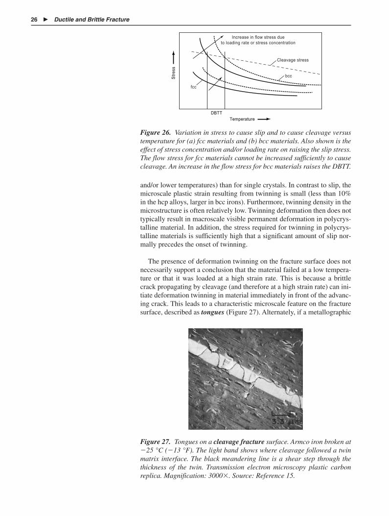
The temperature dependence of deformation by slip is high in the bccmaterials as well as in hcp titanium and zirconium and lower in the fccmaterials and other hcp materials. A large temperature dependence sug-gests that an increased loading rate can cause fracture to change from aductile to a brittle mechanism at a given temperature (Figure 26). The tem-perature dependence of twinning is also probably high, but the normalstress required for cleavage is not a strong function of temperature.
Polycrystalline materials (most, but not all commercial alloys) maydeform or fracture by the above mechanisms (transgranular, or TG, defor-mation or fracture), but they may also deform and fracture in the grainboundaries (intergranular, or IG, deformation or fracture). The conditionsrequired for mechanical twinning are more severe (higher loading rates
26 � Ductile and Brittle Fracture
������
����
���������
� ����� � ���� ������ ���
�� ���� � ��� �� ������ �� �� �����
������ ������
���
���
Figure 26. Variation in stress to cause slip and to cause cleavage versustemperature for (a) fcc materials and (b) bcc materials. Also shown is theeffect of stress concentration and/or loading rate on raising the slip stress.The flow stress for fcc materials cannot be increased sufficiently to causecleavage. An increase in the flow stress for bcc materials raises the DBTT.
and/or lower temperatures) than for single crystals. In contrast to slip, themicroscale plastic strain resulting from twinning is small (less than 10%in the hcp alloys, larger in bcc irons). Furthermore, twinning density in themicrostructure is often relatively low. Twinning deformation then does nottypically result in macroscale visible permanent deformation in polycrys-talline material. In addition, the stress required for twinning in polycrys-talline materials is sufficiently high that a significant amount of slip nor-mally precedes the onset of twinning.
The presence of deformation twinning on the fracture surface does notnecessarily support a conclusion that the material failed at a low tempera-ture or that it was loaded at a high strain rate. This is because a brittlecrack propagating by cleavage (and therefore at a high strain rate) can ini-tiate deformation twinning in material immediately in front of the advanc-ing crack. This leads to a characteristic microscale feature on the fracturesurface, described as tongues (Figure 27). Alternately, if a metallographic
Figure 27. Tongues on a cleavage fracture surface. Armco iron broken at�25 °C (�13 °F). The light band shows where cleavage followed a twinmatrix interface. The black meandering line is a shear step through thethickness of the twin. Transmission electron microscopy plastic carbonreplica. Magnification: 3000�. Source: Reference 15.
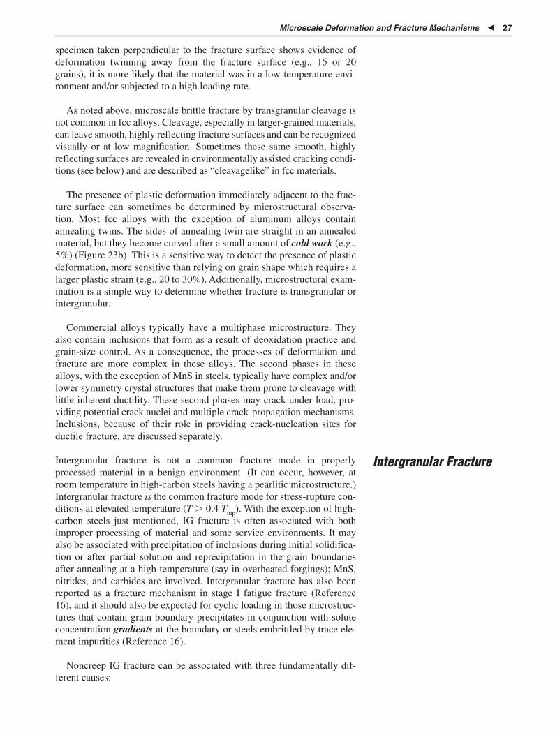
Microscale Deformation and Fracture Mechanisms � 27
specimen taken perpendicular to the fracture surface shows evidence ofdeformation twinning away from the fracture surface (e.g., 15 or 20grains), it is more likely that the material was in a low-temperature envi-ronment and/or subjected to a high loading rate.
As noted above, microscale brittle fracture by transgranular cleavage isnot common in fcc alloys. Cleavage, especially in larger-grained materials,can leave smooth, highly reflecting fracture surfaces and can be recognizedvisually or at low magnification. Sometimes these same smooth, highlyreflecting surfaces are revealed in environmentally assisted cracking condi-tions (see below) and are described as “cleavagelike” in fcc materials.
The presence of plastic deformation immediately adjacent to the frac-ture surface can sometimes be determined by microstructural observa-tion. Most fcc alloys with the exception of aluminum alloys containannealing twins. The sides of annealing twin are straight in an annealedmaterial, but they become curved after a small amount of cold work (e.g.,5%) (Figure 23b). This is a sensitive way to detect the presence of plasticdeformation, more sensitive than relying on grain shape which requires alarger plastic strain (e.g., 20 to 30%). Additionally, microstructural exam-ination is a simple way to determine whether fracture is transgranular orintergranular.
Commercial alloys typically have a multiphase microstructure. Theyalso contain inclusions that form as a result of deoxidation practice andgrain-size control. As a consequence, the processes of deformation andfracture are more complex in these alloys. The second phases in thesealloys, with the exception of MnS in steels, typically have complex and/orlower symmetry crystal structures that make them prone to cleavage withlittle inherent ductility. These second phases may crack under load, pro-viding potential crack nuclei and multiple crack-propagation mechanisms.Inclusions, because of their role in providing crack-nucleation sites forductile fracture, are discussed separately.
Intergranular fracture is not a common fracture mode in properlyprocessed material in a benign environment. (It can occur, however, atroom temperature in high-carbon steels having a pearlitic microstructure.)Intergranular fracture is the common fracture mode for stress-rupture con-ditions at elevated temperature (T 0.4 Tmp). With the exception of high-carbon steels just mentioned, IG fracture is often associated with bothimproper processing of material and some service environments. It mayalso be associated with precipitation of inclusions during initial solidifica-tion or after partial solution and reprecipitation in the grain boundariesafter annealing at a high temperature (say in overheated forgings); MnS,nitrides, and carbides are involved. Intergranular fracture has also beenreported as a fracture mechanism in stage I fatigue fracture (Reference16), and it should also be expected for cyclic loading in those microstruc-tures that contain grain-boundary precipitates in conjunction with soluteconcentration gradients at the boundary or steels embrittled by trace ele-ment impurities (Reference 16).
Noncreep IG fracture can be associated with three fundamentally dif-ferent causes:
Intergranular Fracture

28 � Ductile and Brittle Fracture
� Brittle, second-phase particles and/or films in grain boundaries
� Fracture where no film is visible and due to impurity atom segrega-tion at the grain boundary
� Environmentally induced fracture where there is neither a grain-boundary precipitate or solute segregation
The causes for IG fracture can be categorized as follows (Reference17): (1) environmentally assisted fracture, (2) errors in heat treatment,and (3) normal practice. Relative to the latter, normal practice couldinclude, for example, fracture in the case of a carburized steel (due atleast in part to the large prior-austenite grain size found in this region).Environmentally assisted fracture could be just behavior at elevated tem-perature, but it could also include interaction of the material with theenvironment. This would include hydrogen embrittlement, liquid metalembrittlement, oxidation or reduction of second phases in the grainboundaries, radiation embrittlement, and stress-corrosion cracking.These topics are specifically considered later in this lesson. Some specif-ic examples of IG fracture include:
� Grain-boundary carbide films due to eutectoid divorcement in low-carbon steels and grain-boundary hypereutectoid cementite in car-burized or hypereutectoid steels
� Iron nitride grain-boundary particles or films in nitrided steels
� Temper embrittlement in heat treated steels due to segregation ofphosphorus, antimony, arsenic, or tin
� Grain-boundary carbide precipitation in stainless steels (“sensitiza-tion”)
� Improperly hardened, high-strength aluminum alloys resulting incoarse, grain-boundary precipitates and a denuded region adjacentto the grain boundary
� Overheating of material during hot forming—can result in exces-sive grain size and also partial liquation or eutectic melting; canalso result in partial solution of second phases and/or inclusions thatreprecipitate during cooling
� Embrittlement of molybdenum by interstitials (carbon, nitrogen,oxygen)
� Embrittlement of copper by antimony
� Reduction of Cu2O in tough pitch copper by hydrogen
� Hydrogen embrittlement by grain-boundary absorption of hydrogen
� Stress-corrosion cracking (sometimes)
� Liquid-metal embrittlement (LME)—e.g., mercury in brass, lithiumin 304 stainless steel
� Solid-metal embrittlement (SME)
� Embrittlement due to a large prior austenite grain size in quenchedsteels (and therefore in the heat-affected zone of a weldment)

Ductile Fracture and Necking � 29
Ductile Fractureand Necking
Tensile testing of a smooth ductile member is a convenient way to intro-duce the correlation between material behavior and the resulting appear-ance of the fracture surface. When a specimen is loaded, it initiallydeforms elastically and then, at larger loads above the yield strength,deforms by a combination of elastic and plastic deformation. If the load isincreased still further, it reaches a maximum value and then decreases tosome lower value where fracture occurs (Figure 28). Careful observationwill show that below the maximum load, the diameter of the specimendoes not change with position along the gage length. (The small-scalechange in cross section at Lüder bands is neglected.) However, once themaximum load is exceeded, the specimen diameter is no longer constantalong its length, and the specimen is said to have necked (Figure 2). Neck-ing in a fractured, axially loaded member indicates gross overloading.
The actual shape of the load-elongation curve after plastic deformationinitiates is controlled by both strain hardening and strain-rate hardening.Strain hardening causes the flow stress to increase with an increase instrain; strain-rate hardening causes the flow stress to increase with anincrease in strain rate. Qualitatively, the larger the difference between theyield stress and the tensile strength, the greater the strain-hardening capa-bility. Therefore, materials cold worked prior to testing have little strain-hardening capacity.
The ability to see the neck in the specimen depends on the amount ofstrain hardening and of strain-rate hardening. Consider first just strainhardening. As the specimen extends, it decreases in cross section (geomet-ric softening), so the actual stress on the cross section is increased. At thesame time, the plastically deformed material is strain hardened so that itsflow stress is increased. Up to the maximum load, strain hardening isgreater than geometric softening, and deformation remains uniform alongthe length of the specimen. Beyond the load maximum, the increase in flowstress of the geometrically softened material does not increase sufficiently
���
�
�
� �
���� ����� ��� ��������
���� ������
�� ���
������ ������������ ��
� ���� �
��
�� ��
Figure 28. Load-extension curve for a ductile metal.

30 � Ductile and Brittle Fracture
to stop flow in the smallest-diameter region, that is, the neck. Flow inregions contiguous to the neck essentially stops. Therefore, the ability tosee a neck in a tensile specimen depends on strain hardening. If there is nohardening, necking starts when plastic deformation starts and the strain isnot distributed along the length of the specimen.
The strain at the onset of necking correlates well with the magnitude ofthe strain-hardening exponent (n in � K�n). If that exponent is small,the length of the neck is decreased. In common metallic engineering mate-rials that are not cold worked the amount of strain hardening is usuallylarge enough to cause the neck to have a length of the order of the diame-ter of a cylindrical specimen, and it is therefore readily visible.
Most, but not all, materials also strain-rate harden when tested at roomtemperature. Once necking initiates in the tensile specimen, the diameter inthe neck is smaller than the diameter outside the neck, so the strain rate ishigher inside the neck than outside the neck [�� � (1/A)(�A/�t)]. The flowstress of this material is therefore increased above that of the material outsideof the neck causing the neck to grow along the length of the specimen. Somematerials strain-rate soften when tested at room temperature, and this cancause a dramatic change in the appearance of the fracture surface (seebelow). Strain-rate hardening typically initially increases as service tempera-ture increases above room temperature, but then it decreases at high fractionsof the melting point where dynamic recovery and recrystallization occur.
If a necked, but not fractured tensile specimen, is sectioned longitudinally,it is apparent that crack initiation started along the centerline of the speci-men on a plane macroscopically normal to the applied load, initially grow-ing outward in a radial direction (Figure 29). Before necking initiates in thespecimen, the stress is the same at any location along the gage length. Fail-ure could then initiate at any point anyplace in the specimen. Once neckinginitiates in the specimen, the stress distribution is no longer constant alongthe length or across the cross section. Figure 30 shows that both the axialstress and the hydrostatic stress are highest (more constraint) near the cen-terline of the necked region, which then becomes the predicted andobserved macroscale crack-initiation site. After some growth in the trans-verse plane, the crack turns and runs on a plane of maximum shear stress.This is because geometric constraint is highest along the centerline of thespecimen but is reduced at positions closer to the surface of the specimen.Progressive crack growth leads to the familiar cup-and-cone fracture asso-ciated with fracture of ductile cylindrical specimens (Figure 2).
The macroscopic appearance of the fracture surface is characterized bya central fibrous zone, a region containing ridge marks and a shear zone(Figure 31). Ridge marks point back to the crack-initiation site and are animportant feature for determining these sites. As pointed out earlier, thecoarseness and definition of the ridge marks depend on the generalstrength level of the material, test temperature, and loading rate. Ridgemarks are usually visible without magnification, but sometimes somewhathigher magnification (e.g., to 5 diameters) is required Therefore, low-magnification examination is desirable if the crack-initiation site is notvisible with the naked eye.
MacroscopicAppearance of the
Fracture Surface

Microscopic Appearance of the Fracture Surface � 31
Figure 29. Longitudinal section through a necked tensile specimen. Frac-ture has initiated in the center of the specimen normal to the applied load.After some growth on this transverse plane, the crack turns and runs on aplane of high shear stress as shown. Source: Reference 18.
Stre
ss, k
g/m
m2
00
20
140
40
60
80
100
120
20 40
Radius, %
60 80 100
Longitudinalstress
Maximumshear stress
Radial stress
Circumferential stress
Hydrostatic stress
Longitudinalstress
Maximumshear stress
Radial stress
Circumferential stress
Hydrostatic stress
Figure 30. Stress components in a necked tensile specimen. Adapted fromReference 19.

32 � Ductile and Brittle Fracture
Top view
Side view
F
R
S
S
F, FibrousR, RadialS, Shear lip
RF
Figure 31. The ductile fracture of a tensile specimen showing three possi-ble zones. (a) Centerline fibrous. (b) Radial zone (which may or may notbe present). (c) Shear zone. Source: Reference 20, p 217.
Figure 32. The change in reduction of area with volume fraction secondphases (inclusions). Source: Reference 21, p 22.
The size of the cup (fibrous zone) and the reduction in area measuredon the broken specimen depend in part on the volume fraction of second-phase particles/inclusions (Figure 32). A large volume fraction of secondphases results in a small reduction in area and a large fibrous zone. Alter-natively, if the volume fraction is low, the reduction in area at fracture canapproach very large values; more than 95% as in annealed, commercially

Microscopic Appearance of the Fracture Surface � 33
pure aluminum (1100-O). In such a case, the fibrous region of the fracturecan become diminishingly small. Such a fracture process is sometimesdescribed as ductile rupture, sometimes as plastic attenuation. Highanisotropy within the matrix may cause the fracture surface to be noncir-cular, sometimes resulting in a knife-edge fracture (i.e, highly elliptical).If the material is a single-phase alloy with very few second-phase parti-cles, fracture cannot initiate by microvoid coalescence. In that case, frac-ture can be initiated within a “shear band” or, if local heating occurs dur-ing deformation, within an “adiabatic shear band.” Shear bands andfracture initiation within shear bands are discussed below.
When a tensile specimen containing elongated inclusions is sectionedlongitudinally after fracture, it is observed that the inclusions in the shearzone of the fracture have been rotated and now lie parallel to the fracturesurface (Figure 33). The width of the band containing the rotated inclu-sions is quite narrow, and it described as a shear band. Shear-band forma-tion—localization of shear strain to a narrow band—is a natural conse-quence of plastic deformation. Whether shear bands develop and arevisible depends on component geometry (that is, the state of stress), mate-rial properties, and the total strain at fracture. They are more visible whenstrain to fracture is increased, as in compression loading relative to tensileloading. (See the discussion in Lesson 2 for compression loading.)
Doing work on a specimen by plastic deformation results in a temper-ature rise in the specimen (about 95% of the energy required to producethe plastic deformation is dissipated as heat). If the heat is not conductedaway from the site of deformation, local heating results. This in turn low-ers the yield strength and further concentrates the strain. In this case, theshear bands are described as adiabatic shear bands. In extreme cases oflarge section sizes, poor thermal conductivity, and high strain rates,
Figure 33. The cup and shear wall side of a cup-and-cone ductile frac-ture. The black indications are inclusions. Note how the inclusions areturned and rotated within a narrow band adjacent to the fracture surface.(a) As polished. (b) Etched. Source: Reference 22, p 227.

34 � Ductile and Brittle Fracture
Orange Peel
phase changes can occur within the band. One example is the formationof thin bands of untempered martensite within shear bands in explosivelyloaded steels.
Although the external shape of the cross section at fracture and theshape of the cupped region are usually both circular, this is not always thecase. As noted previously, strong preferred orientation of the grains in the specimen can cause the shape to be noncircular. If the necked region isnot circular, it should be expected that the mechanical properties (espe-cially ductility and toughness) vary with orientation in the material.
When a ductile material having a smooth surface is pulled to fracture,there is usually some roughening of the external surface of the specimenadjacent to the fracture that increases as the grain size increases. Howev-er, if the grain size of the material is very large, the complete surface ofthe specimen becomes very rough, and, in fact, individual grains can beseen on the surface of the specimen (Figure 34). This appearance isdescribed as orange peel. There is still some ductility at fracture, but thecup-and-cone appearance characteristic of a small grain size may disap-pear. The presence of orange peel very likely indicates improper heattreatment.
When prismatic specimens having a large width-to-thickness ratio areloaded in tension, the fracture-surface topography may be different fromthat shown above for cylindrical specimens. Square specimens show thesame features as cylindrical specimens (Figure 35). There is necking inboth the width and thickness directions (rather than radial in the cylindri-cal specimen), and there is a fibrous zone and shear zone. A ridged pat-tern may or may not be present. For moderate width-to-thickness speci-mens, necking can still be observed on both the width and thickness facesof the specimen, but final fracture occurs on a plane containing the widthdirection (Figure 36). There may be only one shear plane in this finalfracture.
As the width-to-thickness ratio is increased still further, the orientationof the fracture surface changes to one in which a trough evident on the
Sheet and PlateSpecimens
Figure 34. Tensile fracture of a large-grained cartridge brass. The speci-men has elongated, but there is no cup-cone fracture. The surface is roughand reveals individual grains (6.35–12.7 mm, or 0.25–0.5 in.). The com-mon name for this surface roughness is orange peel.

Microscopic Appearance of the Fracture Surface � 35
Figure 35. Fracture surface of a prismatic tensile specimen showing acentral fibrous zone, radial marks, and a shear zone. Source: Reference 23.
Figure 36. (a) View of a prismatic steel tensile specimen showing the fracture surface and necking.Shear lips are visible on the fracture surface and there is a small fibrous zone in the center of the spec-imen (not visible in fractograph). (b) Fracture surface of a 6061-T6 aluminum tensile specimen.Width/thickness ratio � 2/1. Necking and shear lips are visible as is a central fibrous zone. There is noradial zone. Courtesy of Patrick Werner, University of Tennessee.
face of the specimen is inclined to the width direction (Figure 37). Thespecimen now contains two types of inhomogeneous shear: one describedas a “diffuse neck” and the second described as a “local neck” in whichshear localization can occur. Bird (Reference 24) has reported that strainlocalization initiates at the intersection of the diffuse neck and the non-necked region of the material. These local necks then grow inward towardthe centerline of the specimen. There are then five possible locations forfracture initiation. Cracking may initiate at the surface of the specimen

36 � Ductile and Brittle Fracture
Figure 37. Ductile fracture within a local neck of a tensile specimen (width/thickness ratio �13.5). A diffuse neck is also visible. Fracture initiation is within the shear band at the edge ofthe specimen. (a) OFHC copper. (b) 400 Monel.
within the local neck (four sites) or at the intersection of two shear bands,where the strain is twice as large as it is in a single shear band. Puttick(Reference 25) has shown this crack initiation in aluminum single crystalsloaded in tension. Others have reported crack initiation at the intersectionof shear bands in compression. Figure 37 shows crack initiation at theedge of the specimen within the shear band.
Figure 38 shows a plate of 7075-T6 aluminum (width-to-thickness ratio � 23.5) that was pulled in tension to fracture. This material has littlestrain-hardening capacity and very little or negative strain-rate-hardeningcapacity. All four planes of maximum shear stress are visible on the frac-ture surface. Ridge marks indicate that at least one crack initiated at the (relatively rough) saw-cut edge of the specimen. Other ridge marksprogress from the specimen interior, indicating fracture at the intersectionof the shear bands. There is no central fibrous zone. Figure 39 shows anessentially single shear plane of fracture in a cylindrical specimen of thesame material. There is a fibrous zone in the center of the specimen, but
Figure 38. Tensile fracture of a 7075-T6 plate (width-to-thickness ratio � 23.5). Frac-ture has occurred on all four planes of maximum shear stress. There is no fibrous zone.Fracture has initiated in multiple locations: at the (rough machined) edge of the mate-rial and at the intersection of the shear bands.
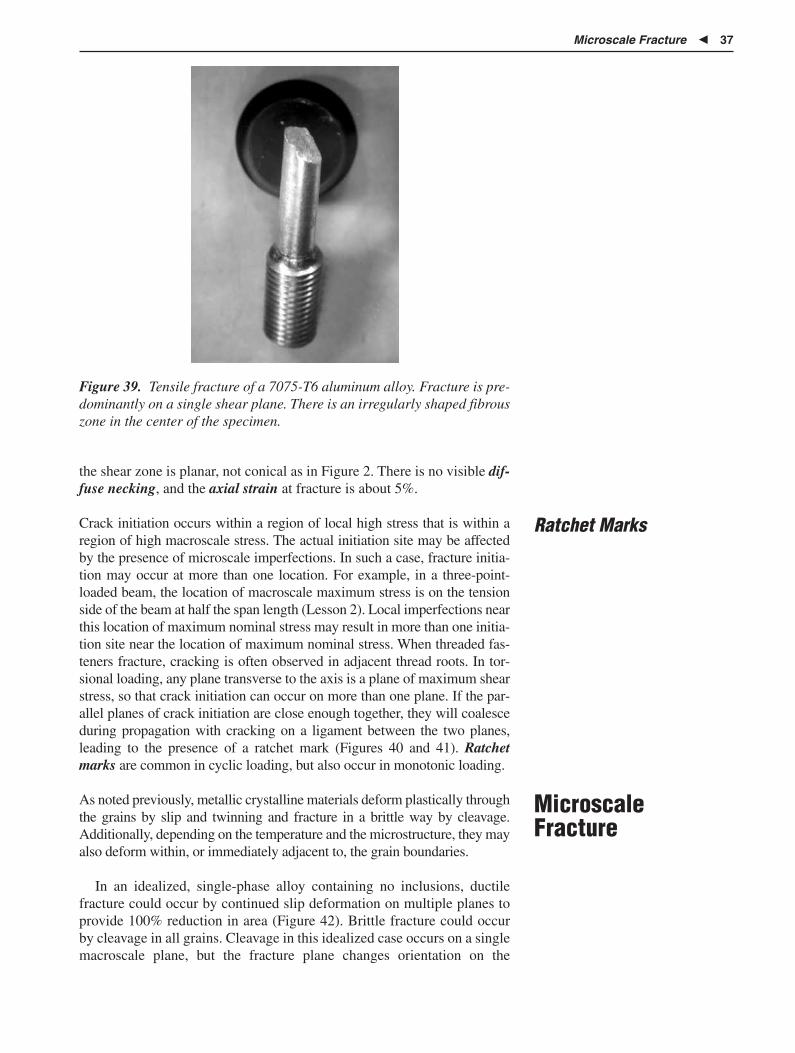
Microscale Fracture � 37
Figure 39. Tensile fracture of a 7075-T6 aluminum alloy. Fracture is pre-dominantly on a single shear plane. There is an irregularly shaped fibrouszone in the center of the specimen.
Ratchet Marks
the shear zone is planar, not conical as in Figure 2. There is no visible dif-fuse necking, and the axial strain at fracture is about 5%.
Crack initiation occurs within a region of local high stress that is within aregion of high macroscale stress. The actual initiation site may be affectedby the presence of microscale imperfections. In such a case, fracture initia-tion may occur at more than one location. For example, in a three-point-loaded beam, the location of macroscale maximum stress is on the tensionside of the beam at half the span length (Lesson 2). Local imperfections nearthis location of maximum nominal stress may result in more than one initia-tion site near the location of maximum nominal stress. When threaded fas-teners fracture, cracking is often observed in adjacent thread roots. In tor-sional loading, any plane transverse to the axis is a plane of maximum shearstress, so that crack initiation can occur on more than one plane. If the par-allel planes of crack initiation are close enough together, they will coalesceduring propagation with cracking on a ligament between the two planes,leading to the presence of a ratchet mark (Figures 40 and 41). Ratchetmarks are common in cyclic loading, but also occur in monotonic loading.
As noted previously, metallic crystalline materials deform plastically throughthe grains by slip and twinning and fracture in a brittle way by cleavage.Additionally, depending on the temperature and the microstructure, they mayalso deform within, or immediately adjacent to, the grain boundaries.
In an idealized, single-phase alloy containing no inclusions, ductilefracture could occur by continued slip deformation on multiple planes toprovide 100% reduction in area (Figure 42). Brittle fracture could occurby cleavage in all grains. Cleavage in this idealized case occurs on a singlemacroscale plane, but the fracture plane changes orientation on the
MicroscaleFracture

38 � Ductile and Brittle Fracture
(a) (b) (c) (d) (e)
B
B
B
B
D
B, Brittle on plane(s) of max normal stressD, Ductile on plane(s) of max shear stress
Multiple crack orientations possible.Cracking may occur on planes of max normal stress and max shear stress.Multiple cracking may lead to ratchet marks as in (c) or (d).
T
T
D
DD
DD
Reversedloading
Cracking in torsional loading
Figure 40. Schematic showing all possible ratchet marks that may be creat-ed in torsion loading so that cracking on multiple planes is likely. The maxi-mum shear stress has the same magnitude as the maximum normal stress.See Lesson 2 for more details. If cracking occurs on two closely spaced par-allel planes, the two cracks tend to coalesce as they grow toward the interior.
Radial marks
Radial
Connectingligament
Fractureplane
(a)
Figure 41. A ratchet mark forming in bending loading of a circular section. (a) Schematicview of a ratchet mark for a component loaded in bending. (b) Ratchet mark in a specimenloaded in bending. Source for (b): Reference 26.
microscale as the crack propagates across grain boundaries. Differentfracture-surface morphologies are observed depending on the orientationrelationship between two grains. Often, when a propagating cleavagecrack crosses a grain boundary, there is usually nucleation on multipleplanes in the new grain. These cracks subsequently coalesce as the crackpropagates, creating a characteristic feature known as a river pattern (Fig-ure 43). Coalescence of the multiple cracks “down river” indicates thecrack-propagation direction. Microscale river patterns, like macroscaleradial and chevron patterns, point back to the crack-initiation site.
Commercial polycrystalline alloys contain second phases and inclusionsof varying shape and deformability as well as lamellar structures. Thesemicrostructural constituents provide additional mechanisms of crack initia-tion and propagation that are not present in single-phase alloys. Inclusions
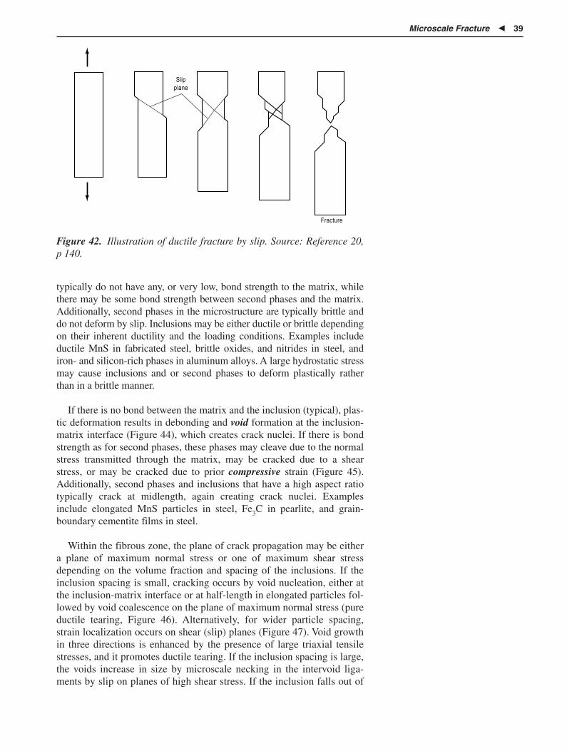
Microscale Fracture � 39
Slipplane
Fracture
Figure 42. Illustration of ductile fracture by slip. Source: Reference 20, p 140.
typically do not have any, or very low, bond strength to the matrix, whilethere may be some bond strength between second phases and the matrix.Additionally, second phases in the microstructure are typically brittle anddo not deform by slip. Inclusions may be either ductile or brittle dependingon their inherent ductility and the loading conditions. Examples includeductile MnS in fabricated steel, brittle oxides, and nitrides in steel, andiron- and silicon-rich phases in aluminum alloys. A large hydrostatic stressmay cause inclusions and or second phases to deform plastically ratherthan in a brittle manner.
If there is no bond between the matrix and the inclusion (typical), plas-tic deformation results in debonding and void formation at the inclusion-matrix interface (Figure 44), which creates crack nuclei. If there is bondstrength as for second phases, these phases may cleave due to the normalstress transmitted through the matrix, may be cracked due to a shearstress, or may be cracked due to prior compressive strain (Figure 45).Additionally, second phases and inclusions that have a high aspect ratiotypically crack at midlength, again creating crack nuclei. Examplesinclude elongated MnS particles in steel, Fe3C in pearlite, and grain-boundary cementite films in steel.
Within the fibrous zone, the plane of crack propagation may be eithera plane of maximum normal stress or one of maximum shear stressdepending on the volume fraction and spacing of the inclusions. If theinclusion spacing is small, cracking occurs by void nucleation, either atthe inclusion-matrix interface or at half-length in elongated particles fol-lowed by void coalescence on the plane of maximum normal stress (pureductile tearing, Figure 46). Alternatively, for wider particle spacing,strain localization occurs on shear (slip) planes (Figure 47). Void growthin three directions is enhanced by the presence of large triaxial tensilestresses, and it promotes ductile tearing. If the inclusion spacing is large,the voids increase in size by microscale necking in the intervoid liga-ments by slip on planes of high shear stress. If the inclusion falls out of

40 � Ductile and Brittle Fracture
Figure 43. River patterns that develop during cleavage fracture. Multiple crack reinitiationsoccur when the propagating crack crosses a grain boundary. In (a), crack propagation is from7 o’clock to 2 o’clock. In (b) propagation is from 1 o’clock to 5 o’clock. (c) Schematic showingthe effect of a grain boundary to cause reinitiation of the cleavage crack. (a) and (b) Source:Reference 27. (c) Source: Reference 28.
the fracture surface, slip plane extrusions are sometimes visible on thewall of the matrix, and these extrusions should not be confused withfatigue striations. Whether the volume fraction of inclusions is large orsmall, this ductile fracture process of void nucleation, growth and coales-cence is known as microvoid coalescence (MVC). This process is themost common mechanism for ductile fracture. If the volume fraction ofsecond-phase particles is sufficiently low, crack initiation cannot occurby this mechanism. The required low volume fraction of inclusions istypically not obtained in commercial and especially polyphase materials.The fracture appearance at the microscale due to MVC is often describedas being dimpled, hence the term dimple rupture (Figure 48).

Microscale Fracture � 41
Figure 44. Debonding at a MnS inclusion in heat treated SAE 4140.Courtesy of Michael West, University of Tennessee.
Figure 45. Cracked cementite particles in a low-carbon steel due to priorcold work. (a) Nital etch.
After a macroscale crack has been created in the specimen, constraint islost, and deformation continues in a ductile manner by plane-stress load-ing in the remaining ligament. Figure 33 shows the microstructuralappearance of the shear zone. Note that the elongated MnS particles,which were originally parallel to the axis of the specimen, have rotatedand lie parallel to the fracture surface in the shear band. Also note that thisregion of intense shear strain is quite narrow. The presence of inclusionsor second phases in the shear band can facilitate crack propagation bydebonding at inclusion-matrix interfaces.
A dual dimple size is sometimes observed (Figure 48). Quenched-and-tempered steel microstructures typically contain large, weakly bonded

42 � Ductile and Brittle Fracture
(a) Initial state
(c) Coalescence of voids with the crack tip
(b) Void growth at the crack tip
Figure 46. Pure ductile tearing on the plane of maximum normal stress.Source: Reference 29, p 280.
(a) Inclusions in a ductile matrix (b) Void nucleation (c) Void growth
(d) Strain localization between voids (e) Necking between voids (f) Void coalescence and fracture
Figure 47. Schematic of ductile fracture by void coalescence. Source: Reference 29, p 270.
inclusions in conjunction with smaller carbide particles. Age-hardeningaluminum alloys may contain large second phases (e.g., CuAl2) in con-junction with smaller particles rich in iron and silicon. For steels, debond-ing occurs first at the inclusion-matrix interface and later at a higher stressby debonding at second-phase particles. Qualitatively, larger particles orinclusions create larger dimples, so if fracture initiates at both inclusionsand second-phase particles, a bimodal distribution of dimple sizes isobserved.

Microscale Fracture � 43
Figure 48. Dimple rupture. Note the variation in dimple size associatedwith the variation in MnS size in the dimples. Source: Reference 2.
Recent work on an aluminum-lithium alloy suggests different behaviorin this alloy system (Reference 30). Careful in situ fracturing in the SEMpermitted a detailed study of the fracture process as microcrackingoccurred in front of the advancing crack tip. The alloy contained severaltypes of second-phase particles, some iron- and silicon-rich that are pres-ent in all aluminum alloys, and other phases containing copper, magne-sium, zirconium, and titanium. It was concluded that the iron- or silicon-rich phases that were very small played no part in the fracture process.The other phases, which were not cracked prior to loading the specimen,in some cases cracked during deformation (larger particles) and, in othercases, did not (smaller particles). However, the important point is thatthere was no debonding and void growth observed at the interfacebetween the second phase and the matrix. Debonding at the inclusion-matrix interface did not initiate the fracture process. The primary crackmoved through the matrix nominally normal to the applied load. If a suffi-ciently large second-phase particle in front of and on a closely spaced par-allel plane as the advancing primary fractured, the primary crack was thendeflected slightly and the crack within the particle became a part of theprimary crack. The implication is that debonding may be the most com-mon mechanism to create crack nuclei, but it may not be the only possibleprocess.
In high-strength, limited-ductility alloys, ladle additions for grain-sizerefinement may result in the presence of nondeformable, faceted inclu-sions (e.g., nitrides). These inclusions can initiate cracking in the adjacentmatrix due to stress concentration at the corners of the inclusions.
When quenched-and-tempered steels are tempered, the fracture surfaceis often composed of thin ridges containing dimples interspersed betweenregions containing cleavage facets. The macroscale fracture is brittle.Individual grains may or may not be delineated. River patterns are com-mon and indicate multiple crack initiation in front of the macroscale

44 � Ductile and Brittle Fracture
Dimple Morphology andType of Loading
crack. This fracture appearance has historically been described as quasi-cleavage. However, there is nothing “quasi” about the cleavage thatoccurred. Current preference is to describe the fracture process as “cleav-age” (Figure 49).
High-magnification examination of the fracture surface reveals dimpleshape. Dimple shape can eliminate some possible loading conditions andalso indicate the direction of crack propagation. Figure 50 shows void for-mation for axial, bending, and shear loading. For axial loading, the dimplesformed around the second phases are circular. For shear and bend loading,they are elongated and open on one end (parabolic shape). There is oftenlittle elongation of the dimples in combined axial and bending loading.Each half of the fracture surface should be examined if the dimples are notround in cross section to distinguish bending from shear loading.
Shear loading can occur for two orientations of the applied load (Figure50), described as in-plane shear or edge sliding mode (mode II deforma-tion) and out-of-plane shear, anti-plane shear, or screw sliding mode(mode III deformation, not shown in Figure 50). Mode III deformation isthe deformation mode associated with torsional loading. For Mode IIIdeformation, the dimples are rotated with respect to the direction of crackpropagation. In some ways, the use of the term “mode” to describe thetype of loading is inconvenient as term is also used to describe themicroscale mechanism (slip versus cleavage and/or transgranular versusintergranular fracture) responsible for fracture. The difficulty can be min-imized if the term “loading mode” is used to describe loading conditionsand use of the term “mode” restricted to microscopic scale phenomena.
There are other microscale fractographic features in addition to dimples,cleavage, and river patterns discussed above. Some of these features areassociated with cyclic loading (for example, fatigue striations). Care must
Other MicroscaleFractographic Features
Figure 49. Cleavage in an O1 tool steel quenched and tempered to 10HRC. Source: Reference 31.

Microscale Fracture � 45
Figure 50. Influence of loading conditions on dimple shape in ductilefracture. (a) Equiaxed dimples in tension loading. (b) Open-ended dim-ples in in-plane shear loading (Mode II). Dimples point in opposite direc-tion on opposite sides of the fracture surface. (c) Open-ended dimples inopening mode (mode I). If dimples are elongated, they point in the samedirection on each side of the fracture surface. Source: Reference 28.
be taken to not confuse similarly appearing fractographic features causedby different mechanisms. An untrained observer might confuse the lamel-lar morphology of pearlite, if it is revealed on a steel fracture surface, withfatigue striations. Another somewhat similar-appearing structure is thepresence of slip bands extruded on a smooth surface such as the interfacebetween an inclusion and the matrix or at porosity. Striations and stria-tionlike features are discussed in Lesson 4.
Some care must be taken also to not confuse a cracked surface deposit(mud cracks) with the metal fracture surface. If an electron-dispersiveanalysis by x-ray (EDAX) attachment is available on the SEM, chemicalanalysis will quickly reveal the presence of a nonmetallic surface depositand dried body fluids (Figure 51).
It may be possible to clarify features on the fracture surface by etch-ing. This procedure will delineate a lamellar structure (such as pearlite)or needles of a second phase and distinguish it from structure fatiguestriations. Once the fracture surface has been etched, the material is nolonger in its as-fractured condition. As a result, some caution must beobserved before this is done, and if litigation is involved, judiciallyapproved permission of the proposed procedures is probably required.

46 � Ductile and Brittle Fracture
Figure 51. Mud cracks on the fracture surface of a mild steel weldmenttested in synthetic seawater. Source: Reference 32.
Additionally, there is sometimes a lack of contrast between two phaseson the fracture surface; so if both dimples and cleavage are observed, itmay not be possible to associate cleavage with the second-phase parti-cles and dimples with the matrix. Again, etching the fracture surface canhelp identification. Alternatively, metallographic sections may be takenthrough the fracture surface.
A common crack-initiation site in cast materials is at locations ofshrinkage porosity (Figure 52). Shrinkage porosity is easy to recognizebecause of the characteristic appearance of the revealed dendrites on thewalls of the porosity.
Figure 52. Crack initiation at shrinkage porosity in aluminum casting alloy A356 specimenloaded in bending. Crack initiation at the top of the figure as indicated by a faint ridge pat-tern in the dendritic region. Source: Reference 33.

Summary of Macroscale and Microscale Fractographic Features � 47
The group of features used to identify the location of fracture initiation,crack-propagation direction, and loading conditions are:
� Ridge patterns (including radial lines) and chevrons
� Shear lips
� Ratchet marks
� Surface roughness and light reflectivity
� Crack-arrest lines (more accurately, a change to dimpled rupturefrom cleavage or quasi-cleavage)
� Rubbing and or smeared metal
All of these markings may not be present simultaneously depending onsection size, loading conditions, loading rate, test temperature, and rela-tive motion of the fracture surfaces during crack propagation. If ridge pat-terns or chevrons are present, they point back to the crack-initiation site.In their absence, cracks propagate parallel to shear lips on a multiplanefracture, and, if ratchet marks are present, the crack-initiation site(s) is atthe location of the ratchet mark(s). Surface roughness increases as thecrack propagates, and the roughest region on the surface is the last to fail.The rougher the fracture surface, the more likely the microscale fracturemechanism is ductile, even though the macroscale surface is “flat.”
Brittle fracture in a coarse-grained material causes light reflection fromcleavage facets within individual grains, and the fracture surface appearsbright and shiny. Microscale ductile fractures have a matte, silky dull, ordark gray appearance and are not highly reflective.
Consider a tensile specimen subjected to a rising load and containing acracklike defect on a plane perpendicular to the load (Figure 13). Crackinitiation will occur at some critical load at or adjacent to the imperfec-tion. However, there may be insufficient stored elastic strain energy todrive the brittle crack completely through the cross section, so the crackarrests at some distance into the material. Then the load begins to riseagain causing some (microscale) ductile crack propagation, but theincreased elastic strain energy again causes the crack-propagation mecha-nism to change to microscale cleavage. This can occur a number of timesas the crack propagates across the specimen. Each time the crack arrestsand the microscale fracture mode changes to ductile fracture, a distinctivesmall band is left on the specimen (Figure 53). These bands are describedas crack-arrest lines. Note that they have curvature, but the lines point inthe direction of crack propagation, rather than away from the initiationsite as do radial marks and chevrons. Note too, that the lines do not closealong the centerline in the two thickest specimens in the figure for whichthere is more constraint. Similar features are often observed on Charpyimpact specimens. Crack-arrest lines may also be visible on intermittentlyloaded fatigue fracture surfaces (Lesson 4), where they are identified asbeach marks caused by local oxidation or a change in loading spectrum.
Macroscale visible smeared metal can sometimes be examined toidentify the final direction of separation. Rub marks at the macroscale
Summary ofMacroscale andMicroscaleFractographicFeatures

48 � Ductile and Brittle Fracture
(b)Displacement
Ductile tearing
Load
Crack propagation bycleavage
Figure 53. (a) Crack-arrest lines formed on the fracture surface (dark curved lines thatlook like parabolas pointing “up” in the figure) in an O1 tool steel. Shear lips (dark) arealso visible on the sides of the specimen. Note that the first arrest line occurs at a furtherdistance from the initiating notch as the specimen increases in thickness. Also note thatat intermediate (and larger) thickness, the arrest lines are not closed along the center-line of the specimen, indicating more constraint in this region. Thin dark bands andsmall shear lips on side of specimen show MVC fracture. Fracture in the higher reflec-tivity regions is predominantly by cleavage. Source: Reference 31. (b) Load-extensioncurve for the material shown in (a).
can polish a surface resulting in high reflectivity. They are commonlyassociated with fatigue cracking and in which case the fracture surfacesare in intimate contact At the microscale, rubbing may result in fine, ran-dom-orientation scratches especially if vibration is present, and it mayoften obliterate a crack-initiation site. Alternatively, final separation mayresult in unidirectional rubbing and gouging of the fracture surface, pro-viding some information about loading conditions. Ductile torsional frac-ture often results in a rubbed “swirl pattern” visible on the fracture sur-face (Figure 54).
Figure 54. Fracture surface of a torsion-loaded steering assembly compo-nent that failed in a ductile manner on a plane of maximum shear stress.Note the swirling rubbed pattern on the fracture surface.

Crack-Initiation in Surface-Treated Components � 49
Crack-InitiationSites inManufacturedComponents
Manufactured components may contain manufacturing imperfections thatcan be either geometric or metallurgical. Microscale cracking will alwaysinitiate where the local stress exceeds the local strength of the material.
The distribution of macroscale stresses across a cross section is dis-cussed in Lesson 2. Axial tension until the onset of necking produces auniform local stress across the cross section, while in bending and torsionthe nominal stress is maximum at the surface. Therefore, assuming for the moment that the strength is constant across the cross section, crack-initiation sites in axial loading are equally likely at any place on the crosssection, but are at the surface in bending and torsion. However, manufac-turing operations often create both macroscale and microscale stress con-centrators or, in some instances, cause microscale cracking. Manufactur-ing imperfections typically occur at the centerline and at the surface(discounting surface-treated components).
Note that crack initiation cannot occur at the centerline in bending ortorsional loading. Therefore, the component shown in Figure 55 musthave been loaded axially. The radial pattern diverges from what appears tobe a near-centerline imperfection. There is essentially no stress at thislocation in bending or torsion.
Surface treating (induction hardening, carburizing, nitriding, ion implan-tation) is a common practice to increase both the load-bearing capacityand the wear resistance of parts, especially for cyclic loading conditions.Lesson 4 contains additional details. The issue is raised here to show howa varying microstructure and a varying nominal stress can interact to causesubsurface crack initiation in a location where the nominal stress is notmaximum.
Assume that a component has been surface treated to produce a high-strength and wear-resistant surface and that the component is to be loadedin bending or torsion. With reference to Figure 56, the applied nominalbending or torsional stress varies linearly from the surface as shown. Two
Crack Initiation inSurface-TreatedComponents
Figure 55. Crack initiation in an axially loaded AISI 4340 tensile specimen(ultimate tensile strength � 1945 MPa, or 282 ksi). Radial marks point to asmall defect near the center of the specimen. Source: Reference 34.

50 � Ductile and Brittle Fracture
Surface Center
Material strengththick case
Material strengththin case
Core strength
Stress fromapplied load
Stre
ss
Figure 56. Plot of internal stress versus distance from the surface to thecenterline for bending or torsion loading. Superimposed is a curve ofmaterial strength versus distance from the surface to the centerline for asurface-treated component. Curves are drawn for both a “thin” case anda “thick” case and assume no decarburization has occurred. Failure forthe “thin” case is below the surface. Thick case material would fail at thesurface.
different material strength gradients are shown, one for a “thick” case andone for a “thin” case. Fracture initiation is subsurface for the “thin” case.Subsurface fracture can also initiate if the hardness change from case tocore is too steep and the case is not very deep. This illustrates the fact thatspecifications for the surface treatment of parts should be written with sig-nificant forethought. It is inadequate to just specify a surface hardness. Asecond subsurface hardness is necessary to preclude subsurface failure.
In addition to microvoid formation at inclusions and second phases andcracking in second phases or inclusions, a number of other crack-initiationsites have been observed in commercial alloys. However, not all of theseinitiation sites are to be considered “imperfections” or defects. Crackingalways initiates where the local stress exceeds the local strength. The fol-lowing is a list of potential crack-initiation sites (with some locations ormechanisms listed more than once).
Transgranular:
� Intersection of mechanical twins
� Tempered martensite embrittlement—fracture in ferrite between thecarbides located in the martensite plate boundaries
� Fracture in cementite plates within a pearlite colony normal to thecementite plates
Microscale Crack-Initiation Sites

Crack-Initiation in Surface-Treated Components � 51
� Fracture at pearlite colony boundaries
� Fracture at bainite colony boundaries
� Fracture within ferrite in upper bainite
Grain-boundary related:
� Grain-boundary triple points—may be ductile by shear, ductile nor-mal separation, brittle normal separation
� Cleavage crack initiation at a grain boundary
� Void (R) and wedge (W) crack nucleation and propagation at elevat-ed temperature
� Intersection of a mechanical twin and a grain boundary
� Temper embrittlement at prior austenite grain boundaries in steels
� Adjacent to a grain boundary due to solute denudation (austeniticstainless steels, precipitation-hardenable aluminum alloys, and others)
� At a grain boundary due to partial liquation (incipient melting)
Second-phase or inclusion related:
� Debonding at inclusions and second phases (the dominant ductilefracture mechanism in commercial-purity metallic materials)
� Matrix crack initiation and propagation caused by stress concentra-tion at a faceted second phase
� Matrix crack propagation from a cracked second phase (crackedsecond phase may have been created by prior forming operations)
Fabrication related:
� Matrix propagation from a cracked second phase
� Cracking due to cold work
� Centerline cracking from prior cold work (e.g., a forging burst)
� Shrinkage porosity not closed by working
� At the intersection of a shear band and the surface of the material
� At the intersection of shear bands
� At laps and seams created in forming (forging, wire drawing, etc.)
� At machining marks
� At locations where poor grain flow exits at the surface of a forging
Welding imperfections:
� Incomplete penetration
� Incorrect weld metal profile (reentrant angle)
� In weld metal due to hot tearing

52 � Ductile and Brittle Fracture
� In the heat-affected zone of a steel due to the presence of untem-pered martensite in large prior austenitic grains
Casting imperfections:
� Shrinkage porosity
� At concentrations of casting sludge
� At internal oxide surfaces due to casting splash
Environmental:
� At surface corrosion pits
� Due to hydrogen absorption in grain boundaries (IG)
� Due to aqueous corrosion (TG and IG)
� Due to liquid metal embrittlement along grain boundaries (IG)
� Due to oxygen diffusion and the formation of oxide particles ingrain boundaries (IG)
At elevated temperatures where creep (time-dependent deformation atconstant load) occurs, experimental work indicates that significant viscousflow occurs in or adjacent to the grain boundary in addition to transgranu-lar deformation. As the temperature is increased from room temperature,ductility initially increases, but then it goes through a minimum beforeagain increasing (Figure 57).
Metallographic examination shows that before the maximum in frac-ture strain there is typically some grain growth in the material and that theminimum in Figure 57 is associated with intergranular (IG) fracture ratherthan transgranular (TG) fracture in large-grained material. Location of theminimum depends on the penultimate grain size and loading rate. Abovethe minimum, dynamic recrystallization may occur, in which case fractureis then transgranular in recrystallized material.
Two types of intergranular fracture are recognized: wedge (W)cracking and round (R) cracking (void formation) as shown in Figures58 and 59. Wedge cracking (Figure 59a) occurs at lower temperaturesand higher stresses than does R cracking (Figure 59b). R crackingresults from condensation of vacancies on grain boundaries, which low-ers the grain-boundary area, increasing the stress on the boundary. Nor-mal separation along the grain boundary may occur by a ductileprocess, resulting in the formation of small dimples on the boundary(sometimes described as grain-boundary decohesion) (Figure 60), butthis does not result in significant macroscale plastic deformation. In thetemperature range in which R cracks form, there may also be consider-able porosity formed in grain interiors. The result is that considerableporosity may be visible in metallographic specimens at and adjacent tothe fracture surface (Figure 61). This type of fracture is often termedcavitation fracture.
IntergranularFracture and
Behavior atElevated
Temperature

Intergranular Fracture and Behavior at Elevated Temperature � 53
Figure 57. Variation in ductility with temperature. Fracture below theminimum is transgranular. Fracture in the minimum is intergranular.Fracture above the minimum is transgranular in recrystallized material.Source: Reference 21, p 26.
Figure 58. (a) “W” and (b) “R” cracking. Source: Reference 28.
The fundamental causes for intergranular as opposed to transgranularcracking are fairly limited in number, some of which are associated withimproper heat treatment and may be alloy specific. Because they are lim-ited, the presence of IG fracture can often be used to help identify thecause for failure. Additional causes for IG fracture are discussed later inthis lesson.

54 � Ductile and Brittle Fracture
Figure 59. Cracking at elevated temperature. (a) Wedge (“W”) cracking in nickel at agrain boundary triple point. Source: Reference 35, p 101. (b) “R” cracking. Tensile axisis vertical. Note higher incidence of voids on grain boundaries perpendicular to stress.Source: Reference 36, p 266a.
Figure 60. Intergranular fracture by microvoid coalescence. Source: Ref-erence 28.
Exposure to elevated temperature implies changes in microstructurewith time in service. Plain-carbon steels may graphitize at elevated tem-perature. Cementite present in the microstructure transforms to graphite,resulting in much lower strength and ductility with long-time service. Inan oxidizing atmosphere, decarburization occurs at the surface of thematerial. If decarburization is extensive, oxide formation also results. Notonly is there an oxide coating on the surface, but oxides may be present inthe grain boundaries. The latter can result in intergranular crack propaga-

Imperfections Associated with Heat Treatment � 55
Figure 61. Cavitation fracture in nickel tested at 403 °C (755 °F).Etchant: Mixed acids. Magnification: 35�. Source: Reference 37.
tion. Oxide on the surface of a plain-carbon steel does not form an adher-ent protective barrier so that new material is continually exposed to theatmosphere. In situ graphitization (decomposition of cementite tographite and ferrite) and scaling resistance are both improved by the addi-tion of chromium to steels. In a carburizing atmosphere, hypereutectoidcementite may be formed in the grain boundaries at elevated temperaturewhen the solubility given by the Acm is exceeded, and/or during cooling totemperatures below the Acm (Acm is the temperature at which cementitecompletes solution in austenite). Again, intergranular fracture may result.Also, the high-carbon steel has little inherent ductility.
Nonferrous materials are also subject to several deleterious changes in themicrostructure when subjected to elevated-temperature service. A fewspecific examples include:
� Excessive grain growth at elevated temperature
� Partial solution of inclusions at elevated temperature that reprecipi-tate during cooling, often in the grain boundaries
� Partial liquation of eutectic and divorced-eutectic constituents locat-ed in the grain boundaries
� Creation of coarse, grain-boundary precipitates and a denuded zoneadjacent to the grain boundary
� Materials containing oxides such as tough-pitch copper that becomeunstable in reducing conditions (the oxides are reduced to formpockets of steam that then create large hydrostatic stresses; copperoxides are not present in phosphorus-deoxidized copper, so thismaterial is better suited for service in a reducing environment thantough pitch copper)
A material may lose strength and toughness due to improper thermal pro-cessing, including both time at a temperature and cooling through a tem-perature range, or may lose strength and toughness in service at tempera-ture. There are a large number of embrittling phenomena that can occur,some of which are alloy specific. Some examples are given to illustrate the
ImperfectionsAssociated withHeat Treatment

56 � Ductile and Brittle Fracture
Sensitization ofAustenitic Stainless
Steels
importance of understanding the role of the microstructure in controllingbehavior. A more extensive discussion of embrittlement in steels due toheat treatment can be found in References 17, 38, and 39.
Some austenitic stainless steels after normal commercial processing donot have thermodynamically stable microstructures. These alloys (e.g.,302, 304, 316) contain some low residual carbon in solution that exceedsthe equilibrium solubility unless the carbon has been deliberatelyremoved (321 and 347 grades). If these alloys are heated into the temper-ature range of 675 to 900 °C (1250 to 1650 °F) or slowly cooled throughthat temperature range, chrome-rich carbides precipitate at the grainboundaries, resulting in embrittlement. The material is then said to besensitized. “L” grades of stainless (containing a specified maximum car-bon content) are available but still become embrittled, although therequired time is increased and the degree of embrittlement decreases.Carbide precipitation is accompanied by a chromium-denuded zone adja-cent to the grain boundary. When loaded to failure at room temperature,the fracture path changes from transgranular in unsensitized material tointergranular in the denuded zone, accompanied by a reduction in frac-ture strain, toughness, and corrosion resistance. The denuded zone adja-cent to the grain boundary is anodic relative to the grain interior. Stan-dardized procedures are available to test for this condition Chemical testsdesigned to test for sensitivity are described in ASTM A 708 (Reference40). Similar embrittlement can occur in other fcc alloys containing somechromium and either nitrogen or carbon. If carbides or nitrides precipi-tate due to elevated-temperature service, the denuded zone is not alwaysapparent with metallographic examination, and, in fact, it may not be pre-sent if time at temperature was long enough to homogenize themicrostructure. Fracture can still be intergranular, but corrosion resis-tance is improved (Reference 41).
Ferritic and duplex stainless steels are also sensitive to intergranularcorrosion attack, but the conditions causing embrittlement are differentthan for the austenitic grades. Sensitization occurs after air cooling orquenching from 925 to 1100° C (1700 to 2010 °F). Slow cooling fromthese temperatures does not result in embrittlement. Again, the mecha-nism responsible for embrittlement is the precipitation of chrome-richcarbides and for these materials, also nitrides. Lower solubility of car-bon and nitrogen in the bcc lattice results in precipitation even withwater quenching from high temperatures. The higher diffusion coeffi-cients of nitrogen and carbon permit removal of composition gradientsin the matrix by reheating the material in the temperature range 425 to925 °C (800 to 1700 °F) (and slow cooling permits homogenizationduring cooling). Required times to remove embrittlement after quench-ing are of the order of minutes at 925 °C (1700 °F) and greater at lowertemperatures.
A type of embrittlement similar to that in austenitic stainless occurs in age-hardening aluminum alloy systems and potentially in all age-hardeningsystems. Precipitation of a second phase rich in the solute added for agehardening occurs in the grain boundaries; for example, CuAl2 in 2xxx alu-minum alloys. The solution anneal prior to aging is supposed to take this
Aluminum Alloys

Imperfections Associated with Heat Treatment � 57
phase into solid solution. If cooling from the solution-annealing tempera-ture is not sufficiently rapid and especially if there is some residual secondphase remaining in the grain boundary, solute adjacent to the grain bound-ary diffuses to the preexisting phase in the boundary, creating a denudedzone.
Figure 62 shows denudation in an age-hardening Al-Zn-Mg alloy.Aging response, fracture toughness, and corrosion resistance aredegraded. The situation can be made worse by selection of an improperaging temperature. As for the stainless steels, phase-composition differ-ences create a corrosion couple. However, in the case of aluminumalloys, the couple may be between the grain interior and the precipitat-ed second phases rather than the grain interior and the denuded grain-boundary area.
Partial liquation (also called incipient melting and eutectic melting)can occur during the solution anneal if the temperature and time are notcarefully selected. If the divorced eutectic does not go into solid solutionbefore the material reaches the eutectic temperature, the eutectic reac-tion reverses, causing a pool of liquid of larger volume than the previoussolid in the grain boundaries. When this material resolidifies, localshrinkage occurs, leaving porosity in the grain boundaries (Figure 63).Fortunately, this situation is easy to recognize by metallographic exami-nation.
Incipient melting is also an imperfection that occurs due to overheatingduring hot forging in both ferrous and nonferrous alloys.
Several types of embrittlement can occur in steel depending on composi-tion and heat treatment. They are identified by terms associated with heattreating practice as well as by the temperature ranges in which they occur.Detailed discussions are available in References 17, 38, and 39. In someinstances, embrittlement results in IG fracture. Correct thermal processingof these same steels does not ordinarily result in IG fracture:
Figure 62. Transmission electron micrograph of a precipitate-free zone(PFZ) in an Al-Zn-Mg alloy formed after aging 2.5 h at 180 °C (355 °F).Source: Reference 42.
Embrittlement in Steels
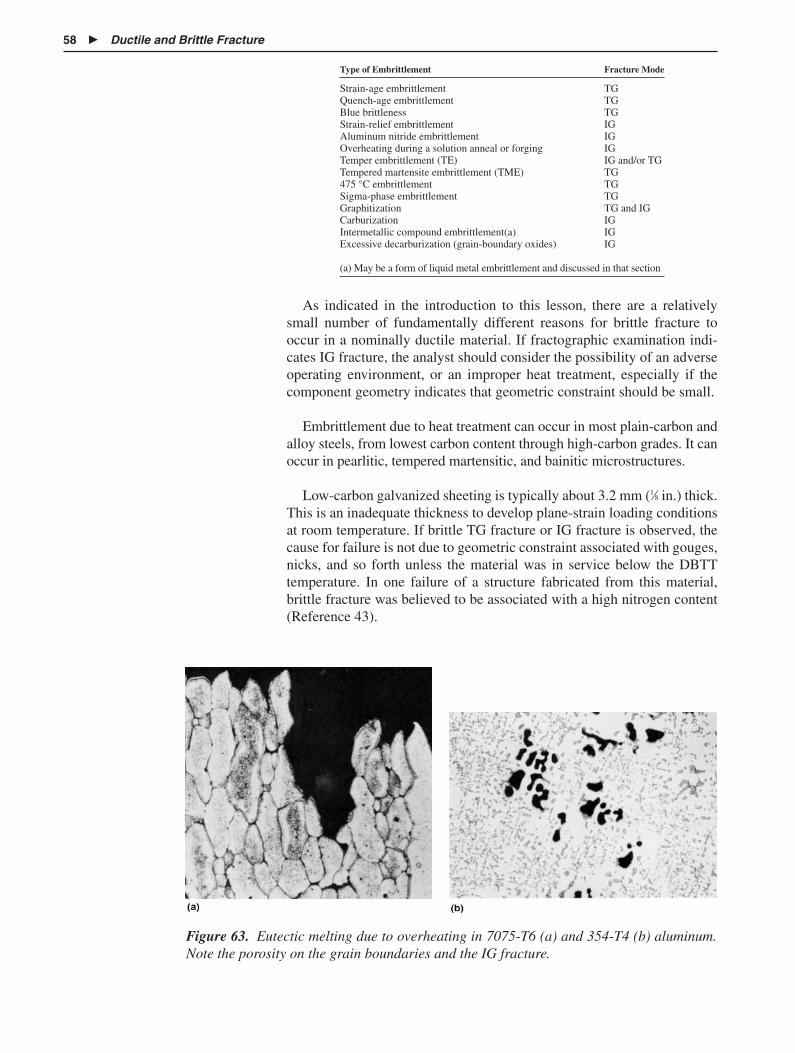
58 � Ductile and Brittle Fracture
Figure 63. Eutectic melting due to overheating in 7075-T6 (a) and 354-T4 (b) aluminum.Note the porosity on the grain boundaries and the IG fracture.
Type of Embrittlement Fracture Mode
Strain-age embrittlement TGQuench-age embrittlement TGBlue brittleness TGStrain-relief embrittlement IGAluminum nitride embrittlement IGOverheating during a solution anneal or forging IGTemper embrittlement (TE) IG and/or TGTempered martensite embrittlement (TME) TG475 °C embrittlement TGSigma-phase embrittlement TGGraphitization TG and IGCarburization IGIntermetallic compound embrittlement(a) IGExcessive decarburization (grain-boundary oxides) IG
(a) May be a form of liquid metal embrittlement and discussed in that section
As indicated in the introduction to this lesson, there are a relativelysmall number of fundamentally different reasons for brittle fracture tooccur in a nominally ductile material. If fractographic examination indi-cates IG fracture, the analyst should consider the possibility of an adverseoperating environment, or an improper heat treatment, especially if thecomponent geometry indicates that geometric constraint should be small.
Embrittlement due to heat treatment can occur in most plain-carbon andalloy steels, from lowest carbon content through high-carbon grades. It canoccur in pearlitic, tempered martensitic, and bainitic microstructures.
Low-carbon galvanized sheeting is typically about 3.2 mm (1⁄8 in.) thick.This is an inadequate thickness to develop plane-strain loading conditionsat room temperature. If brittle TG fracture or IG fracture is observed, thecause for failure is not due to geometric constraint associated with gouges,nicks, and so forth unless the material was in service below the DBTTtemperature. In one failure of a structure fabricated from this material,brittle fracture was believed to be associated with a high nitrogen content(Reference 43).

Imperfections Associated with Heat Treatment � 59
Low-carbon steels are subject to strain-age embrittlement as well asquench-age embrittlement and blue brittleness. Medium-carbon alloysteels that are used in the quenched-and-tempered condition are subjectto both temper embrittlement (also called one-step temper embrittlement)and tempered martensite embrittlement (two-step temper embrittlement).Alloy steels are subject to still other types of embrittlement, such as 475 °C embrittlement in steels containing more than 13% Cr. Tool steelsmay be subject to “500–700 °C embrittlement.” In many, but not all ofthese embrittlement types, embrittlement is associated with the locationand morphology of carbides precipitated in the microstructure. Strain-age embrittlement (SAE) is associated with both nitrogen and carbon, butnitrogen is assumed to play a more important role. Embrittlement mayalso be caused by precipitation or partial solution and subsequent repre-cipitation of inclusions during annealing. Examples include MnS insteels austenitized at a high temperature and thermal embrittlement ofmaraging steels due to precipitation of TiC and/or Ti(C,N) as a result ofbeing cooled too slowly after annealing. Embrittlement may also becaused by aluminum nitride in aluminum-killed steels if the aluminumcontent is too high.
Plain-carbon steels containing ferrite and pearlite (or divorced pearlite)are not normally considered to be age-hardening systems because thedominant strengthening mechanisms are assumed to be associated withthe volume fraction of pearlite, grain size, and cold work. However, thereis an aging effect due to precipitation of TiC and/or Ti(C,N) carbide and/ornitride precipitation that leads to embrittlement. Multiple terms are usedto describe the embrittlement depending on the mechanical and thermalprocessing used.
Strain-age embrittlement occurs by aging of cold-worked, low-carbonsteels, especially rimming grades and capped steels, at room temperature,or slightly higher (as in a hot warehouse during the summer). Two exam-ples where SAE has been identified include punched rivet holes in sheetsteel and in boilers (Reference 44). Cold working of these steels is oftendone to suppress the yield point, and, therefore, these materials often havea small amount of prior cold work. However, when they are heated to tem-peratures at or a little above room temperature and held for some period oftime, the yield point returns due to nitride and possibly some carbide pre-cipitation. The result is a loss of ductility concurrent with an increase inyield strength. In one example (Reference 44), the hardness changed fromabout 70 HRB in the cold-worked material to about 84 HRB in the embrit-tled material after 200 days at 40 °C (105 °F). The time necessary to causeembrittlement decreases as the temperature is increased, and only a fewminutes are required at temperatures near 205 °C (400 °F). Because theembrittlement is associated with the return of sharp yield behavior and aloss in ductility, this type of embrittlement can be identified by tensiletesting of a specimen removed from the component. An alternate andmore common method, if the section thickness permits, is to anneal mate-rial that has been cold worked about 5% at 260 °C (500 °F). Then CharpyV-notch specimens are prepared and tested to determine if there has beena shift in the DBTT. An increase of the DBTT indicates embrittlement as aresult of SAE. Strain-age-embrittled materials fail by cleavage.

60 � Ductile and Brittle Fracture
A similar type of embrittlement, blue brittleness, occurs in plain-car-bon steels and some alloy steels that have been heated between 230 and370 °C (446 and 698 °F). Again, the embrittled material displays anincrease in strength and a decrease in ductility and toughness. The termarises from the color of the oxide scale produced on steels heated intothis temperature range. Embrittlement is again associated with carbideprecipitation, which can be accelerated by prior cold work. Becauseyield strength increases with strain rate, blue brittleness can be pushedto higher temperatures with increased loading rates. Fracture is trans-granular.
Quench-age embrittlement occurs in low-carbon steels that are cooledrapidly from a temperature just below the lower critical temperature (Ac1)and then aged at temperatures near room temperature. There is once againan increase in strength and hardness with a concurrent loss in ductility andtoughness. As with strain-age embrittlement, quench-age embrittlement isa diffusion-controlled process, so that shorter times are required as thetemperature is increased. Additionally, if the temperature at the start ofrapid cooling is decreased further below the Ac1, there is less supersatura-tion of carbon and a concurrent decrease in the degree of embrittlement.Quenching from temperatures below 560 °C (1040 °F) does not result inembrittlement, and carbon contents greater than 0.12% are not suscepti-ble. Like strain-age embrittlement, quench-age embrittlement occurs bytransgranular fracture. Presumably, the fracture will change from MVCto mixed MVC and cleavage and then to essentially total cleavage as thedegree of embrittlement increases. Examples and numeric data are avail-able in Reference 44.
Two types of embrittlement should be recognized in welded assemblies.One type, noticed most in low-carbon steels, is associated with precipita-tion of carbides in the heat-affected zone of the weld. A second type isassociated with higher carbon and solute content and is associated withthe formation of higher-carbon martensite in large-grained prior austenitein the heat-affected zone.
For lower-carbon-content materials, embrittlement may occur during apostweld stress-relief anneal (stress-relief embrittlement). In this case,some limited precipitation occurs both in the grains and at the grainboundaries during initial cooling. The terms heat treat cracking or reheatcracking are also used to describe this behavior.
Embrittlement due to martensite formation can occur in both plain-carbon and alloy steels in the heat-affected zone, depending on the carbonand solute contents. The heat-affected zone is material heated above theupper critical temperature and is located adjacent to the molten weldmetal. As a result, there may be a large amount of austenite grain growth,which increases hardenability. In the lower-carbon contents, martensiteformed during cooling can self temper and embrittlement is minimized.However, above about 0.3% C, the combination of fresh martensite and alarge prior austenite grain size results in low toughness. Depending onconstraint present at the weld, quench cracking may result, and fracturemay be intergranular.
Embrittlement of Weldments

Imperfections Associated with Heat Treatment � 61
The contemporary HSLA steels of which one group has a carbon con-tent of approximately 0.12% and a second group at 0.18 to 0.20% C weredeveloped specifically to provide weldable-grade steels having yieldstrengths greater than 345 MPa (50 ksi). The low carbon content results ina steel free of embrittlement.
Quench-and-temper operations for heat treatable steels are common oper-ations designed to impart maximum toughness sometimes in conjunctionwith a high yield strength. Yet, if times and temperatures for the temperingoperation are not selected properly and if certain trace alloying elementsare present, the resulting fracture toughness may be low. Unfortunately,although it is common to use hardness measurements as a quality-controlcheck of the heat treatment, hardness changes with tempering typically donot reveal the embrittlement.
Embrittlement during tempering operations has been recognized formany years, but debate concerning the fundamental causes of embrittle-ment has changed as new research tools have become available. Oneadvancement occurred with the development of electron microscopy,which made it possible to examine carbide morphology and location, anda second advancement occurred with the development of Auger spec-troscopy, which made it possible to obtain chemical analysis from near-surface material on a fresh fracture surface.
Embrittlement today is felt to be due to three different mechanisms:(1) an improper carbide morphology and distribution resulting from thetempering of martensite, (2) the decomposition of retained austenite dur-ing tempering, and (3) the presence of some specific impurity elementsand the associated segregation of solute elements during tempering. Allthree factors may be involved in tempered-martensite embrittlement, but itis primarily the third factor that is involved in temper embrittlement. Asso-ciated with these mechanisms in a practical heat treating operation is thepossibility of decarburization and oxide formation in the grain boundariesat the surface of the material.
Tempered martensite embrittlement (TME) occurs in alloy steels inthe tempering temperature range 200 to 370 °C (400 to 700 °F) or duringslow cooling through that temperature range. It is therefore associatedwith tempering operations that produce relatively high strength and hard-ness. One factor involved is the decomposition of martensite to form acarbide and/or the decomposition of thin bands of retained austenite toform either bainite or tempered martensite. A second factor involved andidentified by Auger spectroscopy is the segregation of minor impurities toaustenite grain boundaries. Elements that have been identified include tin,antimony, arsenic, and phosphorus. Tempered martensite embrittlement isstill considered to be incompletely understood today, in part because morethan one mechanism may be involved.
Careful examination of fracture surfaces indicates that fracture can betransgranular, intergranular, or mixed. Some workers report that temper-ing in the lower part of the embrittling range leads to transgranular frac-ture, while tempering in the higher part of the embrittling range leads to
Temper Embrittlementand Tempered-MartensiteEmbrittlement
62 � Ductile and Brittle Fracture
intergranular fracture. Transgranular fracture is associated with carbidemorphology and location, while intergranular fracture is associated withtrace-element segregation.
In the absence of the complicating factors discussed below, TME is asso-ciated with transgranular fracture in ferrite or low-carbon martensite alongprior martensite plate or bainite plate boundaries. During the temperingoperation, martensite initially decomposes to a slightly tetragonal matrixphase and a transition carbide (� � Fe2.4C). The carbide is distributed overthe prior martensite plate as well as at the plate boundaries. At a slightlyhigher tempering temperature, the � carbide and tetragonal ferrite disappearand the equilibrium carbide (Fe3C, cementite) and ferrite appear. A similarmorphology can be produced during transformation of retained austenite to bainite, and the same morphology may also occur in microstructuresisothermally transformed to bainite. So-called upper bainite is a mixture offerrite and a rodlike carbide that forms principally at high-angle bainiteplate boundaries. If the temperature of the bainite formation is in the lowerrange of bainite formation, lower bainite is formed and the carbide is againmetastable, but it is precipitated more uniformly over the bainite plates.Attempts to improve the toughness of the upper bainitic microstructure areonly partially successful. Tempering at high temperatures does improve theupper-shelf toughness, but the DBTT is shifted upward (Reference 50).Fracture occurs within the ferrite in the tempered martensitic or bainiticmicrostructure and also at the bainite packet boundaries.
An additional factor may be involved in some steels. Retained austenitecan be present as thin sheets between the martensite plates after quench-ing. This retained austenite has a high carbon content and, when tempered,forms thin carbide plates in the prior thin bands of retained austenite (Ref-erence 38).
Temper embrittlement (TE) occurs when martensitic microstructuresof alloyed steel are tempered in the range 375 to 575 °C (700 to 1070 °F)or slow cooled through this temperature range after tempering at highertemperatures. The embrittlement is diffusion controlled and therefore timedependent. It is associated with the concentration of certain trace alloyingelements, notably arsenic, antimony, tin, and especially phosphorus.Because it results from tempering at higher temperatures and for longertimes, it is associated with lower strength and hardness. It is a reversibleprocess, in that toughness can be restored by reheating the steel to abovethe embrittlement range (but below the Ac1) followed by cooling rapidlythrough the embrittling range.
It is known that segregation of the embrittling trace-level elements is notsufficient to cause embrittlement. The presence of some other alloying ele-ment such as chromium and manganese is required. Molybdenum, tung-sten, and zirconium greatly reduce embrittlement, and nickel, titanium, andvanadium reduce it slightly (Reference 28). Manganese is routinely addedto steel to improve hardenability and to prevent hot-short behavior. Recentalloy development work has suggested that temper embrittlement can beminimized if the manganese content is reduced from above 0.5% to about0.3%. This then prevents or minimizes embrittlement associated with slow

Environmental Service Conditions � 63
Grain-Size Effects andDeoxidation Practice
EnvironmentalService Conditions
cooling of heavy sections. It has been known for many years that molybde-num is beneficial in reducing TE, but its mitigating effect is related to howmuch is in solid solution versus how much is tied up as carbides. Molybde-num tied up as carbides does not suppress TE.
It is again emphasized that, although it is common to use hardness mea-surements to determine acceptable heat treating, hardness measurementsdo not detect TE or TME (or most other types of embrittlement). Addi-tionally, standard tensile tests using smooth cross sections of TE embrit-tled materials do not indicate the embrittlement, except perhaps for adecreased reduction in area for extreme cases. A standard procedure usedto detect TE is to measure the DBTT using Charpy impact specimens.Embrittled specimens show an increase of as much as 200 to 300 °F in the10 ft � lbf transition temperature. Examination of the fracture surface athigh magnification in the SEM will show whether the fracture is inter-granular or transgranular.
Toughness problems of heat treated steels are sometimes associated with alarge, prior-austenitic grain size, and intergranular quench cracking isfacilitated by a large austenite grain size. Additionally, the yield strength ofthe steel is reduced because of its square-root dependence on grain size. Alarge austenite grain size may be created because of high annealing tem-peratures used in an attempt to homogenize the steel or overheating duringhot forming or forging. High homogenization temperatures may also causeother difficulties. It is common to add manganese to steel to tie up the sul-fur as MnS and therefore to prevent hot-short behavior. However, if thetemperature is too high during annealing or hot working (e.g., tempera-tures of 1040 to 1095 °C, or 1900 to 2000 °F), MnS partially dissolves andsubsequently reprecipitates on austenite grain boundaries during cooling.The result is low fracture toughness and intergranular fracture. Reprecipi-tation of the MnS can, if severe, be identified by its morphology (spher-oidal rather than elongated) and its intergranular location.
The 10 ft � lbf transition temperature of hot-rolled mild steel measuredin a Charpy test can be shifted more than 100 °F due to changes in priorgrain size. Hence, it is desirable from a toughness standpoint to keep theprior-austenitic grain size as small as possible. The traditional means ofpreventing austenite grain growth has been to use a grain-size refiner. Alu-minum has been a common ladle addition for this purpose. However, toomuch aluminum can result in excess aluminum nitrides or oxides in thegrain boundaries and IG fracture.
Service environments include both high and low temperatures as well asthe possible presence of a chemically reactive atmosphere. The change intoughness associated with materials having a bcc lattice (and a few mate-rials having a hcp lattice) at low temperature is discussed earlier in thislesson; this section considers high-temperature behavior.
Plain-carbon steels show little change in properties with an increase inservice temperature until approximately 400 °C (750 °F). Above this tem-perature, several changes in behavior begin to occur: (1) there is a loss inelastic modulus, (2) decarburization of steels results in scale formation
Elevated-TemperatureService in an OxidizingAtmosphere

64 � Ductile and Brittle Fracture
Hydrogen Degradation
and possible oxides in the grain boundaries, (3) fine pearlite begins tospheroidize, (4) cementite in pearlite may decompose to graphite, and(5) time-dependent deformation (creep) begins to contribute to the totalstrain as does strain resulting from thermal expansion.
Plain-carbon steels heated for long-time service at temperatures above425 °C (800 °F) graphitize. That is, cementite in the pearlite decomposesto graphite with a corresponding decrease in elevated-temperaturestrength and ductility. Consequently, it is necessary to stabilize the car-bide in some manner if the steel is to be exposed to long-time, elevated-temperature service. Such is the case in the chemical process industries(piping, reaction vessels, heat exchangers). Graphitization is enhanced inaluminum-killed steels containing more than about 0.025% Al. However,silicon-deoxidized steels can also be prone to graphitization. The standardprocedure to minimize graphitization is to stabilize the carbides by the useof molybdenum and/or chromium additions. Chromium additions providean additional benefit. Plain-carbon steels have poor scaling resistance, andwhen chromium is added to the steel the surface oxide becomes adherent,providing protection to the underlying metal.
The following material is excerpted in part from References 17 and 45.
Hydrogen pickup in steels can lead to severe embrittlement, but otheralloys may also be susceptible. There are multiple sources of hydrogenpickup that include:
� Dissolved hydrogen precipitation upon solidification
� Acid cleaning (pickling) baths
� Electroplating operations
� Water or water vapor, or other hydrogen-containing liquids orincluding methane and hydrogen sulfide
� Pure hydrogen gas
The presence of hydrogen can result in:
� Hydrogen embrittlement
� Hydrogen stress cracking
� Hydrogen environmental embrittlement
� Partial loss of tensile ductility
� Blistering
� Shatter cracks, flakes and fisheyes
� Metal hydride formation
Hydrogen stress cracking is the brittle fracture of a material afterhydrogen absorption. Hydrogen diffuses into the material and collects atregions of high stress concentration. Because some time is required fordiffusion, there is typically a delay time before fracture occurs under load,

Environmental Service Conditions � 65
leading to the (poor) term static fatigue fracture. Fracture occurs at astress below the nominal yield strength, and susceptibility to this type offracture increases as the strength level of the steel increases. Some personsconsider a hardness of 30 HRC or a yield strength in excess of 1100 MPa(160 ksi) to be the threshold values for the occurrence of hydrogen embrit-tlement. Lower-strength materials may suffer a loss in ductility, but frac-ture in a ductile manner. Sensitivity to fracture increases with a decreasein strain rate and an increase in hydrogen content of the atmosphere. Thetemperature dependence of hydrogen embrittlement is low at low temper-atures, increases to a maximum at intermediate temperatures, and thendecreases again at still higher temperatures.
Hydrogen pickup and subsequent embrittlement associated with elec-trochemical corrosion is considered to be a form of stress-corrosioncracking, and they are discussed below.
Some of the following discussion is taken in part from Reference 45, andthe reader is referred to that text for more detail. Stress-corrosion cracking(SCC) is the result of a synergistic interaction of the presence of a materi-al under load (or residual stress) in a corrosive environment. Features ofSCC include:
� The required stress may be very low (considerably less than theyield strength).
� The necessary concentration of the corroding species may also bevery low.
� The amount of corrosion products visible on the surface of the partdoes not correlate with sensitivity to SCC or time to fracture; that is,the part may show little visible indication of an impending failure.
� Stress-corrosion cracking generally occurs in systems that in theunstressed condition show little corrosion attack.
� At the macroscale, SCC fracture is brittle and can occur in alloysthat show considerable ductility in the absence of the corrodingenvironment (e.g., austenitic stainless steel).
� At the microscale, SCC is often, but not always, intergranular.
For those metal systems that rely on a passive film for corrosion protec-tion, SCC occurs when the environment causes film rupture and the film isunable to repair itself. The passive film is quite thin (less than 100 Å) andtypically not macroscale (and in some instances, microscale) visible. Theformation of a protective film and the conditions for its breakdown aremeasured electrochemically via polarization curves (Figure 64). Figure 65illustrates the change in polarization curves for sensitized stainless steel.Because passive film rupture is a necessary prerequisite to SCC, contem-porary laboratory procedures to examine SCC consider it to be a two-stepprocess of crack initiation and crack propagation. Prior to the develop-ment of fracture-mechanics-based concepts, laboratory procedures tostudy SCC used statically loaded tensile and bending specimens exposedto the environment. The time to fracture was measured as a function of the
Stress-CorrosionCracking

66 � Ductile and Brittle Fracture
Figure 64. Potential ranges of stress-corrosion cracking by hydrogenembrittlement, cracking of an unstable passive film, and cracking initiatedby pitting. Source: Reference 45.
Figure 65. Potential curve for an austenitic stainless steel showingchanges in the active corrosion region with degree of sensitization.Source: Reference 45.
applied stress. Today, there are well-established procedures based on lin-ear elastic fracture mechanics to measure crack propagation and the crit-ical value of the stress-intensity factor for propagation in a specific envi-ronment (KISCC). Figure 66 shows typical data and defines three regions ofcrack propagation. Two types of behavior are observed: (1) stage I behav-ior, in which SCC crack growth occurs at diminishingly small values of Kand rises linearly to a plateau and (2) stage I behavior is absent, and thecurve rises almost instantaneously to stage II behavior, which then definesKISCC. Aluminum alloys tend to show stage I behavior while stage I isabsent in stainless steels (Reference 45).

Environmental Service Conditions � 67
Figure 66. Typical subcritical crack-growth rate by stress-corrosioncracking versus the stress-intensity factor. Three regions are defined. StageI is not always present. See text for discussion. Source: Reference 45.
Prior to the development of fracture-mechanics-based concepts, sim-pler laboratory procedures using U-bend and other geometry specimenswere popular and still remain popular today for qualitative work. Thedevelopment of standard tests to measure crack initiation in a corrosiveenvironment is currently an active research area.
Small changes in a variable (say, alloy composition) can initiate crack-ing because of the onset of general film dissolution or pitting. A change indissolved oxygen is also a major factor because the dissolved-oxygen con-centration can shift the corrosion potential to values where a passive filmis not stable.
In addition to anodic polarization curves discussed previously, othertesting procedures have been developed to determine sensitivity to stresscorrosion. Metallographic examination is useful for determining grain-boundary attack. Because a tensile stress is a necessary prerequisite toSCC, several test specimen configurations are available to create bothbending and axial loading as noted previously.
Stress-corrosion cracking can be both transgranular and intergranular.For some alloys, the cracking mode may change from IG fracture to TGfracture depending on the corroding medium. Intergranular fracture isusually associated with microstructures in which a grain-boundary precip-itate is present and in which there is a solute-denuded zone adjacent to thegrain boundary. The grain-boundary precipitate may be quite small anddifficult to identify. Therefore, it is possible for a given alloy to showeither, or both, IG and TG fracture. Transgranular fracture in stress-corrosion systems can create fractographic features in fcc alloys very sim-ilar in appearance to cleavage fracture observed in bcc alloys (see Figures67 to 69). Etch pitting of the fracture surface has been used in an attempt

68 � Ductile and Brittle Fracture
Figure 67. Stress-corrosion cracking IG fracture plus TG fracture groov-ing attack in an 18Cr-10Ni alloy. 5 N H2SO4 0.1 N NaCl. Source: Ref-erence 46, p 133.
Figure 68. Stress-corrosion cracking cleavagelike fracture in a 16Cr-16Ni alloy. Source: Reference 46, p 144.
to identify the fracture planes and therefore to develop possible disloca-tion mechanisms for crack nucleation. Transgranular crack propagation insome instances occurs by the formation of deep crack tunnels that leavedistinctive grooves on the fracture surface. Tearing then occurs subse-quently between the tunnels, resulting in grooved regions bounded bydimples.
Liquid-metal embrittlement (LME) is a phenomenon in which ductilityand fracture stress are reduced by surface contact with a liquid metal. Thefracture stress may be well below the yield strength of nonembrittledmaterial, and the time to fracture decreases as the stress level increases.
Liquid-Metal and Solid-Metal
Embrittlement
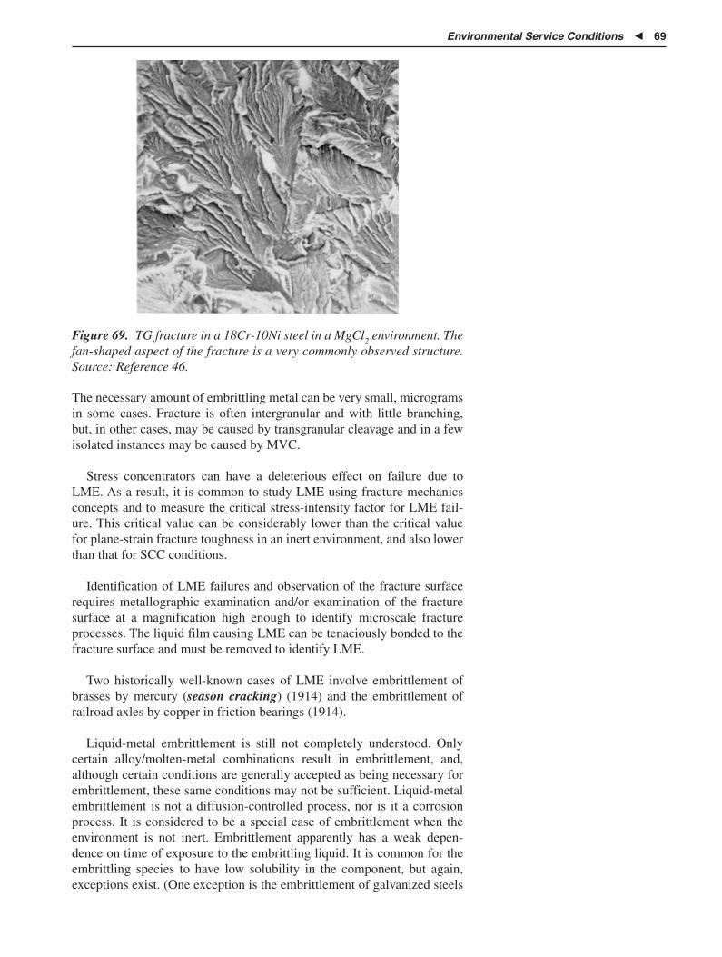
Environmental Service Conditions � 69
Figure 69. TG fracture in a 18Cr-10Ni steel in a MgCl2 environment. Thefan-shaped aspect of the fracture is a very commonly observed structure.Source: Reference 46.
The necessary amount of embrittling metal can be very small, microgramsin some cases. Fracture is often intergranular and with little branching,but, in other cases, may be caused by transgranular cleavage and in a fewisolated instances may be caused by MVC.
Stress concentrators can have a deleterious effect on failure due toLME. As a result, it is common to study LME using fracture mechanicsconcepts and to measure the critical stress-intensity factor for LME fail-ure. This critical value can be considerably lower than the critical valuefor plane-strain fracture toughness in an inert environment, and also lowerthan that for SCC conditions.
Identification of LME failures and observation of the fracture surfacerequires metallographic examination and/or examination of the fracturesurface at a magnification high enough to identify microscale fractureprocesses. The liquid film causing LME can be tenaciously bonded to thefracture surface and must be removed to identify LME.
Two historically well-known cases of LME involve embrittlement ofbrasses by mercury (season cracking) (1914) and the embrittlement ofrailroad axles by copper in friction bearings (1914).
Liquid-metal embrittlement is still not completely understood. Onlycertain alloy/molten-metal combinations result in embrittlement, and,although certain conditions are generally accepted as being necessary forembrittlement, these same conditions may not be sufficient. Liquid-metalembrittlement is not a diffusion-controlled process, nor is it a corrosionprocess. It is considered to be a special case of embrittlement when theenvironment is not inert. Embrittlement apparently has a weak depen-dence on time of exposure to the embrittling liquid. It is common for theembrittling species to have low solubility in the component, but again,exceptions exist. (One exception is the embrittlement of galvanized steels

70 � Ductile and Brittle Fracture
by molten zinc in which case zinc penetrates the grain boundaries duringhot-dip galvanizing.)
Variables of importance include:
� Composition of the base alloy and the liquid metal
� Temperature
� Strain rate
� Grain size
� Thermal/mechanical history
Some combinations resulting in embrittlement can be found in Refer-ence 47. Temperature effects are sometimes unpredictable, but embrittle-ment is usually worst just above the freezing point of the embrittling liquid,although there are several cases in which embrittlement occurs below thefreezing point of the liquid (solid-metal embrittlement, or SME). Anincrease in temperature decreases embrittlement so that LME couples showa ductile-brittle transition with temperature, changing from IG fracture orcleavage to dimpled rupture at higher temperatures. Grain-size effects aresimilar to those for fracture in a benign environment; the fracture stressvaries inversely with the square root of the grain diameter and an increasein grain size increases the DBTT. Strain-rate effects are also similar to thosein a benign environment: an increase in strain rate increases the DBTT.
Materials subjected to a source of neutrons, as in nuclear reactors, maybecome embrittled. The most obvious change in mechanical properties isan increase in the DBTT as measured by a Charpy test (Figure 70) or anincrease in the nil-ductility temperature as measured by a drop-weighttest. Variables affecting behavior include:
� Composition and microstructure
� Neutron fluence (dosage)
� Temperature
Radiation (Neutron)Embrittlement
Ene
rgy,
ft •
lbf
0−40 0 40 80 120
20
40
60
80
100
12012080400−40−80 160 200 240 280 320
Temperature, °C
Temperature, °F
160°
NDT
5.2 kgm/cm2
NDT
Unirradiated
6 in. A302-B plateCommerical heat
Irradiated550 °F, ~ 3 × 10¹⁹
n/cm2 > 1 MeV
Figure 70. The shift of the Charpy impact curve to higher temperaturesdue to irradiation. Source: Reference 48.

Further Reading � 71
Summary of Conditionsfor Embrittlement
Tempered-martensitic microstructures are less susceptible to embrittle-ment than tempered bainite (especially upper bainite) and pearliticmicrostructures. Phosphorus (above 0.015%) and copper (above 05%) aredetrimental to behavior.
Below the DBTT temperature, embrittled steels show both transgranu-lar cleavage and IG fracture, while the unembrittled material shows onlycleavage. Above the DBTT, embrittled materials show a change to smallerand shallower dimples.
Austenitic stainless steels have also been reported to show degradedbehavior due to irradiation-assisted SCC when exposed to radiation in ahot-water environment (Reference 49).
Embrittlement of a nominally ductile member can occur as the result of(1) low-temperature service (bcc materials), (2) high-temperature serviceat the minimum in ductility with temperature, (3) improper heat treating,(4) several oxidizing and reducing manufacturing and service environ-ment conditions. In many, but not all of these cases, fracture is intergranu-lar rather than transgranular. Since the number of causes for IG fracture issomewhat limited and is often alloy specific, identification of IG fracturein a failed component is helpful in deciding root cause for failure. Identi-fication may be made by either examination of the fracture surface or ametallographic section adjacent to the fracture surface. A metallographicsection taken perpendicular to the fracture surface is a good way to exam-ine the role of the microstructure in controlling the fracture process.Unfortunately, this test is destructive and therefore may require approval iflitigation is involved.
This lesson covers several topics that have been reported extensively in theliterature. A few selected references are cited below for the major areascovered in this lesson.
General
� Failure Analysis and Prevention, Vol 11, 9th ed., Metals Handbook,American Society for Metals, 1986 (in revision 2002)
Fracture Mechanics
Fracture mechanics and the general issue of brittle fracture induced bynonmetallurgical variables
� T.A. Anderson, Fracture Mechanics, 2nd ed., CRC Press, 1995(excellent source for analytical fracture mechanics)
� J. Barsom and S. Rolfe, Fracture and Fatigue Control in Structures,2nd ed., Prentice Hall, 1987 (not much materials content)
� R.W. Hertzberg, Deformation and Fracture Mechanics of Engineer-ing Materials, 4th ed., John Wiley, 1996, Section 13.7 (containsmaterials issues as well as behavior of nonmetallics)
Further Reading

72 � Ductile and Brittle Fracture
Embrittlement in Steels
� G. Vander Voort, Embrittlement of Steels, Properties and Selection:Irons, Steels, and High-Performance Alloys, Vol 1, ASM Handbook,ASM International, 1990, p 689–736
Environmentally Assisted Fracture
� E.E. Stansbury and R.A. Buchanan, Fundamentals of Electrochemi-cal Corrosion, ASM International, 2000 (no creep-related informa-tion)
Failure Analysis and Fractography
� C. Brooks and A. Choudhury, Metallurgical Failure Analysis,McGraw-Hill, 1993
� Fractography, Vol 12, 9th ed., Metals Handbook, ASM Interna-tional, 1987
1. D.A. Ryder, “The Elements of Fractography,” NTIS AD-734 619,U.S. Dept. of Commerce, 1971
2. Ductile and Brittle Fracture, Failure Analysis and Prevention, Vol11, 9th ed., Metals Handbook, American Society for Metals, 1986,p 82–101
3. H. Tada, P.C. Paris, and G.R. Irwin, Stress Analysis of CracksHandbook, ASM International, 2000
4. Fracture Mechanics Properties of Carbon and Alloy Steels, Fatigueand Fracture, Vol 19, ASM Handbook, ASM International, 1996,p 614–654
5. R.J. Jesseman and G.J. Murphy, Some Effects of SpecimenDesign, Sample Location and Material Strength on Through-Thickness Tensile Properties, Thickness Tension Testing of Steel,STP 794, R.J. Gladowski, Ed., ASTM, p 109
6. A.D. Wilson, Comparing the Effect of Inclusions on Ductility,Toughness, and Fatigue Properties, Through Thickness TensionTesting of Steel, STP 794, ASTM, 1983, p 130
7. A.G. Atkins and Y.-W. Mai, Elastic and Plastic Fracture, HalstedPress, 1985
8. D. Wulpi, Understanding How Components Fail, ASM Interna-tional, 1999
9. W.A. Spitzig et al., Fracture Toughness and Surface Topography,Electron Fractography, STP 436, ASTM, 1968
10. F.R. Larson and F.L. Casrr, “How Failures Occur–Topography ofFracture Surfaces,” Met. Prog., Feb 1964 and Source Book in Fail-ure Analysis, American Society for Metals, 1974, p 26
11. R. Roberts and C. Newton, Bulletin 265, Welding Research Coun-cil, Feb 1981
References

References � 73
12. J. Barsom and S. Rolfe, Fracture and Fatigue Control in Struc-tures, 2nd ed., Prentice Hall, 1987
13. R.W.K. Honeycombe, The Plastic Deformation of Metals, Ameri-can Society for Metals, 1984
14. G. Bodine, “The Effect of Strain Rate upon the Morphology ofHigh Purity 26 Per Cent Chromium 1 Per Cent Molybdenum Fer-ritic Stainless Steel Tubing,” M.S. thesis, University of Tennessee,Knoxville, TN, 1974
15. Atlas of Fractographs, Fractography, Vol 12, 9th ed., Metals Hand-book, ASM International, 1987, p 224
16. R.W. Hertzberg, Deformation and Fracture Mechanics of Engi-neering Materials, 4th ed., John Wiley, 1996, Section 13.7
17. G. Vander Voort, Embrittlement of Steels, Properties and Selec-tion: Irons, Steels, and High-Performance Alloys, Vol 1, ASMHandbook, ASM International, 1990, p 689–736
18. K.E. Puttick, Philos. Mag., Vol 4, 1959, p 964
19. E.R. Parker, H.R. Davis, and A.E. Flanigan, ASTM Proc., Vol 46,1946; as shown in D. McLean, Mechanical Properties of Metals,John Wiley, 1962, p 228
20. C. Brooks and A. Choudhury, Metallurgical Failure Analysis,McGraw-Hill, 1993, p 140
21. G.E. Dieter, Introduction to Ductility, Ductility, American Societyfor Metals, 1984, p 1
22. F.A. McClintock and A.S. Argon, Mechanical Behavior of Materi-als, Addison-Wesley, 1966, p 522
23. G.F. Vander Voort, Visual Examination and Light Microscopy,Fractography, Vol 12, 9th ed., Metals Handbook, ASM Interna-tional, 1987, p 91
24. J.E. Bird, T. Pollock, and S.K. Srivastava, Flow Localization Dur-ing Plane Strain Punch Stretching of a Ferrite-Austenite Steel,Metall. Trans., Vol 17A, 1986, p 1537
25. K.E. Puttick, Necking and Fracture in Aluminum Crystals, ActaMetall., Vol 11, 1963, p 989
26. D.A. Bales, “Fatigue Behavior of Decarburized Steels,” M.S. the-sis, University of Tennessee, Knoxville, TN, 1975
27. H.C. Burghard and N.S. Stoloff, Cleavage Phenomena and Topo-graphic Features, Electron Fractography, STP 436, ASTM, 1968, p 46
28. V. Kerlins and A. Phillips, Modes of Fracture, Fractography, Vol12, 9th ed., Metals Handbook, ASM International, 1987, p 12–71
29. T.A. Anderson, Fracture Mechanics, 2nd ed., CRC Press, 1995
30. H. Tada, T. Kobayashi, and A. Takahashi, Micromechanism ofFracture in Wrought Aluminum Alloy Containing Coarse InclusionParticles, Aluminum Trans., Vol 1 (No. 1), 1999, p 109
31. W.S. Lin, “Scanning Electron Metallography of Plane Stress toPlane Strain Fracture Transition in Tool Steel,” M.S. thesis, Uni-versity of Tennessee, Knoxville, TN, 1974

74 � Ductile and Brittle Fracture
32. Y. Kirsunai, M. Tanaka, and E. Yoshihisa, Metall. Trans. A, Vol29A, April 1998, p 1293
33. G. Powell, S. Cheng, and C.E. Mobley Jr., A Fractographic Atlasof Casting Alloys, Battelle Press, 1992
34. C.D. Beachem and D.A. Meyn, Fracture by Microscopic PlasticDeformation Processes, Electron Fractography, STP 436, ASTM,1968, p 77
35. F. Garofalo, Ductility in Creep, Ductility, American Society forMetals, 1967
36. A.J. Kennedy, Processes of Creep and Fatigue in Metals, Oliver &Boyd, Edinburgh, 1962
37. E. Bloom, “Effect of Grain Size and Strain Rate on the ElevatedTemperature Ductility of Nickel,” M.S. thesis, University of Ten-nessee, Knoxville, TN, 1964
38. C. Brooks, Heat Treatment of Plain Carbon and Low Alloy Steels,ASM International, 1996, p 171
39. K.-E. Thelning, Steel and Its Heat Treatment, Butterworths, 1975
40. “Practice for Detection of Susceptibility to Intergranular Corrosionin Severely Sensitized Austenitic Stainless Steel,” A 708, AnnualBook of ASTM Standards, ASTM
41. R.H. Adler, W.T. Becker, and J.B. Smith, Challenges in Compre-hensive Failure Analysis in a Complex System, Failure PreventionThrough Education Conference Proceedings, J. Scutti, Ed., ASMInternational, 2000
42. A.J. Sedriks, P.W. Slattery, and E.N. Pugh, Trans. ASM, Vol 62,1969, p 238
43. W.T. Becker, Brittle Failure in a Grain Storage Bin, Handbook ofCase Histories in Failure Analysis, Vol 2, ASM International,1993, p 470
44. B.R. Queneau, Ed., Embrittlement of Metals, American Society forMetals, 1956
45. E.E. Stansbury and R.A. Buchanan, Fundamentals of Electrochem-ical Corrosion, ASM International, 2000
46. J. Scully, Theory of Stress Corrosion Cracking, NATO, Brussels, 1971
47. M.H. Kamdar, Liquid-Metal Embrittlement, Failure Analysis andPrevention, Vol 11, 9th ed., Metals Handbook, American Societyfor Metals, 1986, p 225–238
48. L.E. Steele, “Influence of Composition on the Fracture Toughnessof Commercial Nuclear Vessel Welds,” NRL Report 7095, NavalResearch Laboratory, Washington, D.C., 1970
49. E.P. Simonen and S.M. Bruemmer, Radiation Effects on Environ-mental Cracking of Stainless Steels, J. Met., Dec 1998, p 52
50. D.R. Johnson, “Toughness of Tempered Bainitic Microstructuresin a 4150 Steel, M.S. thesis, University of Tennessee, Knoxville,TN, 1990

Metric Conversion Factors
To convert from To Multiply by
in. mm 25.4in. m 25.4 � 10�3
mil �m 25.4�in. �m 25.4in.2 m2 6.45 � 10�4
in.3 m3 1.64 � 10�5
ft m 3.048 � 10�1
ft2 m2 9.29 � 10�2
ft3 m3 2.831 � 10�2
oz g 2.834 � 10lb kg 4.536 � 10�1
Btu J 1.054 � 103
Btu/lb � °F J/kg � K 4.18 � 103
Btu/ft � h � °F W/m � K 1.730in./in. � °F m/m � K 1.8
psi Pa 6.895 � 103
psi kPa 6.895ksi kPa 6.895 � 103
ksi MPa 6.895ksi � in.1/2 MPa � m1/2 1.099
ksi MPa 1.099ozf gf 28.4lbf kgf 4.536 � 10�1
lbf N 4.448ft � lbf N � m (or J) 1.356lbf/in.2 kgf/cm2 14.223lbf/in.3 kgf/m3 2.768 � 104
lb/ft3 kg/m3 16.019lb/in.3 g/cm3 2.768 � 10lb/in.3 kg/m3 2.768 � 104
gal (U.S. liquid) L 3.785gal (U.S. liquid) m3 3.785 � 10�3
lb/gal g/L 119.826ft/gal ml/L 748
°F °C (°F � 32)/1.8°F K (°F 459.67)/1.8°C °F (°C � 1.8) 32°C K °C 273.15K °C K � 273.15
Multiple and submultiple units
1012 tera 10�1 deci109 giga 10�2 centi106 mega 10�3 milli103 kilo 10�6 micro102 hecto 10�9 nano10 deka 10�12 pico
Abbreviations
J joule m meter Pa pascalkgf kilogram force mm millimeter K kelvinL liter N Newton W watt
√m√in.
ASM International®
Materials Park, OH 44073-0002www.asminternational.org


