There are various types of lasers. Each one has different characteristics that depend,to a large extent, on the active medium used for laser action. In this chapter, we firstdiscuss the major types of lasers, based primarily on the active medium. In addition,we also discuss recent developments in laser technology, especially with regard toindustrial lasers, specifically those used for materials processing. The principal lasercategories include the following.
1. Solid-state lasers
2. Gas lasers
3. Liquid dye lasers
4. Semiconductor (diode) lasers
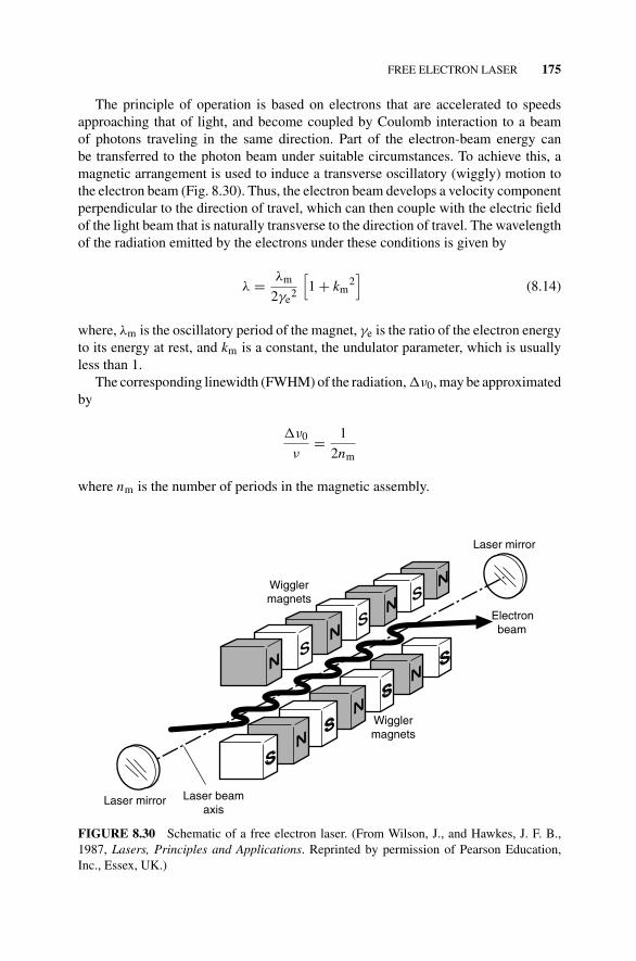
5. Free electron lasers.
Even though semiconductor lasers are also based on solid material, they are con-sidered separately since the pumping and lasing mechanisms are different. In eachcategory, a number of lasers have been developed using different active media. Thedifferent laser types are discussed in the order listed above in the following sec-tions. The basic concepts related to each general type are discussed using one or twoexamples for illustration. The basic characteristics of some major industrial lasersare summarized in Appendix 8B, and the wavelength range of common lasers aresummarized in Appendix 8C.
The notations used to represent the electron configurations in other laser texts areusually complex. In this book, we use an unconventional but very simple representa-tion, which starts with the letter E with a subscript that designates the energy level,for example, Ex, indicating energy level x.
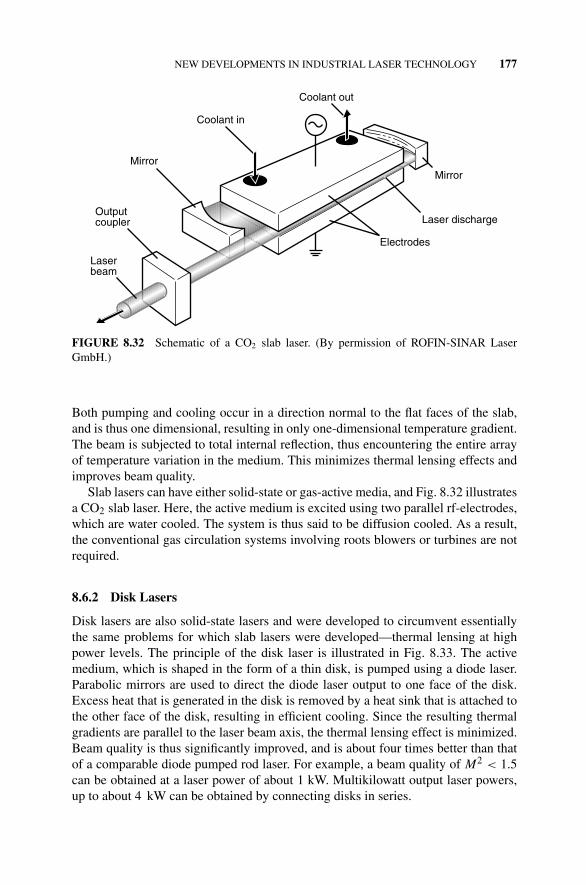
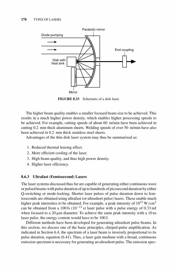
In addition to the major laser categories, we shall discuss new developments inindustrial laser technology. Ultrafast (utrashort pulse or femtosecond), slab, disk,and fiber lasers are considered separately under this category. Ultrafast lasers (whichare also based on solid-state laser technology) use special techniques, in addition tomode-locking, to achieve the ultrashort pulse duration. Slab and disk lasers are alsogiven special consideration even though they both use solid-state active media. Slablasers can also use gas active media, and may be optically or electrically pumped.
Fiber lasers are also based on solid-state laser technology and can generate ultrashortpulse outputs.
8.1 SOLID-STATE LASERS
Solid-state lasers normally use an insulating crystal or glass as the host lattice. In itis embedded the active medium, which is either a dopant or an impurity in the hostmaterial. The crystal host material does not participate directly in the lasing action.The dopant is the component that participates directly in laser action. It is normally atransition metal or rare earth element, and it substitutes for some of the atoms in thehost material, rather than being an interstitial impurity. For the solid-state lasers thatwe consider under this section, the active medium is shaped in the form of either arod or a slab. Since the rod form is the traditional shape for the active medium, we useit as illustration in most of our discussion. The slab configuration is discussed at theend of this section. The rod is normally cylindrical in shape, with ends that are groundand polished to be plane and parallel. Its dimensions depend on the active mediumbeing used. The ends of the rod may either be silvered (one completely and the otherpartially), in which case the rod constitutes the optical cavity, or the rod may be placedbetween two external mirrors. Pumping is commonly done using a flash lamp, andthe configuration involves either a cylindrical cavity with elliptical cross-section ora helical flashtube (see Chapter 3, Fig. 3.1). The rod temperature may be controlledby circulating air or liquid around it. Otherwise, the heat generated can change thecavity dimensions and consequently, the cavity modes.
Most solid-state lasers generate pulsed beams, even though some generate contin-uous wave outputs. Their coherence lengths are thus relatively short, making themunsuitable for a number of interference-based applications. However, the significantamount of energy available in each pulse makes them attractive to applications thatrequire such energy bursts. These include resistor trimming, initiation of thermonu-clear fusion, and spectroscopic research. Common types of solid-state lasers includethe ruby, Nd:YAG, and Nd:Glass lasers. These are further discussed in the followingsections.
8.1.1 The Ruby Laser
The significance of the ruby laser is that it was the first laser to be successfullymade and operated. The rod is a single crystal of ruby, which consists of crystallinealuminum oxide (Al2O3) that is doped with chromium. The chromium constitutesabout 0.05% of the rod by weight and replaces some of the aluminum ions. Theresulting material is pinkish in color. The aluminum oxide (sapphire) is the hostlattice while the chromium ions, Cr3+, constitute the active medium. The size of theruby rod normally ranges from 0.5 to 1.0 cm in diameter and from 5 to 20 cm inlength.
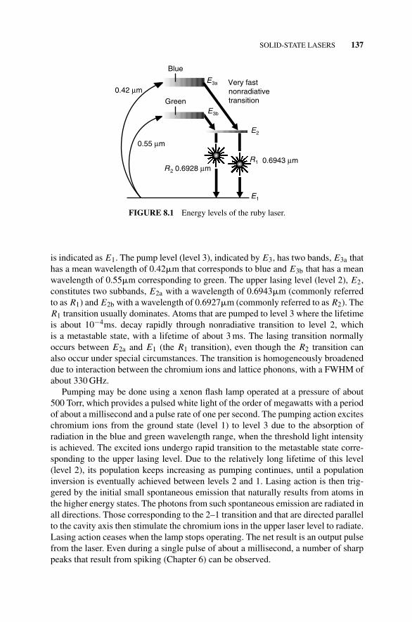
The energy levels involved in the lasing action are those of the chromium ions, andthese are illustrated in Fig. 8.1. This is a three-level system. The ground level (level 1)
SOLID-STATE LASERS 137
Very fastnonradiativetransition
Blue
Green
0.55 μm
0.42 μm
E2
E1
E3b
E3a
R2
R1 0.6943 μm0.6928 μm
FIGURE 8.1 Energy levels of the ruby laser.
is indicated as E1. The pump level (level 3), indicated by E3, has two bands, E3a thathas a mean wavelength of 0.42�m that corresponds to blue and E3b that has a meanwavelength of 0.55�m corresponding to green. The upper lasing level (level 2), E2,constitutes two subbands, E2a with a wavelength of 0.6943�m (commonly referredto as R1) and E2b with a wavelength of 0.6927�m (commonly referred to as R2). TheR1 transition usually dominates. Atoms that are pumped to level 3 where the lifetimeis about 10−4ms. decay rapidly through nonradiative transition to level 2, whichis a metastable state, with a lifetime of about 3 ms. The lasing transition normallyoccurs between E2a and E1 (the R1 transition), even though the R2 transition canalso occur under special circumstances. The transition is homogeneously broadeneddue to interaction between the chromium ions and lattice phonons, with a FWHM ofabout 330 GHz.
Pumping may be done using a xenon flash lamp operated at a pressure of about500 Torr, which provides a pulsed white light of the order of megawatts with a periodof about a millisecond and a pulse rate of one per second. The pumping action exciteschromium ions from the ground state (level 1) to level 3 due to the absorption ofradiation in the blue and green wavelength range, when the threshold light intensityis achieved. The excited ions undergo rapid transition to the metastable state corre-sponding to the upper lasing level. Due to the relatively long lifetime of this level(level 2), its population keeps increasing as pumping continues, until a populationinversion is eventually achieved between levels 2 and 1. Lasing action is then trig-gered by the initial small spontaneous emission that naturally results from atoms inthe higher energy states. The photons from such spontaneous emission are radiated inall directions. Those corresponding to the 2–1 transition and that are directed parallelto the cavity axis then stimulate the chromium ions in the upper laser level to radiate.Lasing action ceases when the lamp stops operating. The net result is an output pulsefrom the laser. Even during a single pulse of about a millisecond, a number of sharppeaks that result from spiking (Chapter 6) can be observed.
138 TYPES OF LASERS
The output of a ruby laser may be about 10–50 MW with a pulse duration of about10–20 ns when Q-switched. Since ruby lasers are three-level lasers, high-thresholdenergy is needed to excite at least half of the Cr3+ ions to achieve population inversion.High levels of energy are thus required to operate them, resulting in extensive heatingof the laser rod. This, coupled with the low thermal conductivity of ruby, makes themdifficult to operate in continuous mode. As a result, they are not widely used anymore.
8.1.2 Neodymium Lasers
Neodymium (Nd) lasers have either a crystal or glass material as the host lattice, andthis is doped with neodymium ions, Nd3+, that constitutes the active medium. Theenergy levels are thus those of the neodymium ions and are illustrated in Fig. 8.2.These are four-level lasers. The ground level (level 0) is the E0 energy level. Again,the pump level (level 3) has two bands, with E3a having a mean wavelength of0.73�m, while E3b has a mean wavelength of 0.8�m. The upper lasing level (level2) is E2 with a lifetime of about 0.23 ms., and from there, transition occurs to thelower lasing level (level 1), E1. This transition is also primarily homogeneouslybroadened with a FWHM of about 195 GHz, and a transition wavelength of 1.06�min the infrared range. Atoms are pumped from level 0 to level 3, from which theyundergo rapid nonradiative decay to level 2, which is a metastable state. The energydifference between level 1 and the ground state, level 0, is such that hpν � kBT
at room temperature, so that level 1 is practically empty under thermal equilibriumconditions. Furthermore, transition from level 1 to level 0 is very fast, and occurs bynonradiative processes. Any atoms that make a transition to level 2 then essentiallyresult in a population inversion. Neodymium lasers thus have a much lower inversionthreshold requirements than ruby lasers. The traditional pumping schemes are similarto those outlined for the ruby laser. There is a variety of host materials that are usedfor neodymium lasers, but the most common ones are YAG and glass.
0.73 μm
ν = 2 × 103cm–1
E2
0.80 μm
E0
1.06 μm
E1
E3a
E3b
FIGURE 8.2 Energy levels of neodymium lasers.
GAS LASERS 139
8.1.2.1 The Nd:YAG Laser The host lattice for this laser is a crystal of yttriumaluminum garnet (YAG) with the chemical composition Y3 Al5 O12, where the Nd3+ions (about 0.1–2%) substitute for some of the Y3+ ions. Operation of the Nd:YAGlaser can be either in the continuous wave (CW) or in pulsed mode, depending onwhether pumping is continuous or intermittent. A xenon flash lamp may be usedat medium pressure (500–1500 Torr) or a krypton lamp at high pressure (4–6 atm),and the rod size is similar to that of the ruby laser. The power output in CW modevaries from 150 W to 6 kW, and that in Q-switched pulsed mode is of the order of50 MW with a pulse duration of about 20 ps, at a repetition rate of 1–100 Hz. Thehigh-power (up to 2 kW) CW laser may be achieved by having three Nd:YAG rodsin line as a single oscillator, with each rod being arc lamp pumped. The very highpowers (up to 6 kW) are obtained by pumping with a diode laser (Figs 3.3 and 3.4).The efficiency of both pulsed and CW Nd:YAG lasers typically ranges between 1 and3%. Applications of Nd:YAG lasers include laser surgery and materials processing,for example, welding, cutting, drilling, and surface modification.
8.1.2.2 The Nd:Glass Laser The host lattice for the Nd:Glass laser is glass suchas silicate, phosphate, or fluoride glass, with 1–5% Nd3+. It has the advantage that therod size can be much larger (up to 1 m in length and about 50 mm in diameter) than thatfor Nd:YAG since glass can be easily made with high-quality or optical homogeneity(free of residual stresses) to large sizes because of its lower melting temperature. Withpower output per unit volume being comparable to that of Nd:YAG, relatively largerpower outputs can be obtained with this type of laser. Since glass has an amorphousstructure, it has short range order. Thus, the environment and therefore the field ofeach ion is different from that of any other ion. This variation of ion environmentsin the glass matrix results in additional inhomogeneous broadening, and thus a muchbroader bandwidth. The Nd:Glass laser therefore normally operates in multimode.Very short pulse periods, of the order of 5 ps, with high-output powers, can thus beobtained when the output is mode-locked.
One major disadvantage of Nd:Glass lasers is the low thermal conductivity ofglass, which is about an order of magnitude smaller than that of Nd:YAG. This limitstheir usefulness for CW operation, and are thus only used for low-rate pulsed outputs,with a typical output pulse rate of 1 Hz. The relatively high-peak pulse outputs (upto 20 TW) of Nd:Glass lasers enable them to be used in laser-induced nuclear fusionreactions. However, the low pulse rates limit their applicability in manufacturingto such operations as drilling and spot welding, and in the cases where they areacceptable, are able to produce superior quality holes at depth-to-diameter ratios upto 50:1, much higher than what can be achieved with the Nd:YAG laser.
8.2 GAS LASERS
Gas lasers are among the most common form in the laser industry. The power levelsrange from several kilowatts (carbon dioxide (CO2) lasers) to milliwatts (helium–neon (He–Ne) lasers). They can be operated in either the continuous mode or pulsedmode, with output frequencies ranging from ultraviolet to infrared.
140 TYPES OF LASERS
As the name implies, gas lasers use a gaseous medium as the active medium.Common examples are the He-Ne and CO2 lasers. The broadening mechanisms ingas lasers are not as strong as those in solids. Thus, the resulting linewidths, deter-mined primarily by Doppler broadening, are relatively small. This is because collisionbroadening is relatively small due to the low pressures normally used in gas lasers.As a result, the energy levels are relatively narrow, and thus a sharp emission line isessential for excitation. Optical pumping, with its broad emission spectrum, is there-fore not suitable for pumping gas lasers, since it would result in inefficient pumping.Electrical pumping is thus the most common means of exciting the active medium ingas lasers. Pumping is also done by chemical means, with an electron beam, or bygas-dynamic expansion.
When classified by the active medium, one can identify four principal types of gaslasers:
1. Neutral atom lasers
2. Ion lasers
3. Metal vapor lasers
4. Molecular lasers.
8.2.1 Neutral Atom Lasers
The most common example of neutral atom lasers (using inert gases as the activemedium) is the He–Ne laser, which was also the first laser to generate CW output.The active medium in this case consists of 1 part neon to 10 parts helium. This is afour-level laser, and Fig. 8.3 illustrates the energy level schemes of He and Ne.Thehelium atoms are more easily or efficiently excited to the higher levels by electroncollision than are neon atoms. Thus, the electrons that are accelerated by the passage
Helium
Excitationby collision
by Atomiccollisions
Collision withwall
Neon
0.6328 μm
Rapid
3.39 μm
1.15 μm
HE0
HE3b
HE3aNE3a
NE3b
NE1
NE2a
NE2b
NE0
Ne ground stateHe ground state
FIGURE 8.3 Energy levels of the He–Ne system.
GAS LASERS 141
of a discharge through the mixture excite the helium atoms to the metastable higherenergy levels denoted by HE3a and HE3b. These energy levels of helium happen tocoincide with some of the excited states of neon, the NE3a and NE3b levels. Theexcited helium atoms are thus able to transfer energy to neon atoms, which are in theground state when collision takes place between the two. This results in de-excitationof the helium atoms involved to the ground state while the neon atoms are excited tothe higher energy level. This process of energy transfer through collision is referredto as resonant collision or resonant energy transfer, and is so called because thecorresponding energy levels coincide. The process increases the population of theNE3a and NE3b levels of neon relative to the lower NE2a and NE2b levels, resultingin a population inversion between the two sets of levels.
Lasing action occurs between energy levels of the neon atoms. The role of helium isthus to assist in the pumping process. The metastable state of the excited helium atoms(staying at the high level for a relatively long time) makes the energy transfer processmore efficient. The decay time of the upper lasing levels of neon (about 100 ns) isabout an order of magnitude greater than that of the lower lasing levels (about 10 ns),thereby satisfying a necessary condition for CW operation (see Section 4.3).
Even though there are a large number of possible transitions between the sublevelsof the Ne laser transition states, the principal or strongest ones are shown in Fig. 8.3,with transition at wavelengths of 0.633, 1.15, and 3.39�m. The last two wavelengthsfall in the infrared region, while the first one results in the red light, and is the mostcommon mode in which the laser is used. The desired wavelengths can be selectedusing techniques discussed in Chapter 2.
After transition, the atoms in the lower lasing level relax spontaneously to the NE1level which is metastable. Thus, if the temperature of the neon gas is high enough,electrons from the NE1 state may jump back to the NE2a and NE2b levels (Boltzman’slaw). This phenomenon is known as radiation trapping, and will cause the populationinversion between the upper lasing level and the NE2a and NE2b levels to decrease,resulting in quenching.
The three main factors that affect radiation trapping and the population inversionof He–Ne lasers are current density, total and partial gas pressures of He and Ne, anddiameter of the discharge tube. With a higher current density in the discharge tube,the temperature of the gas becomes higher. Therefore, there is an optimum currentdensity that provides maximum pumping power without quenching laser action.
The gas pressures of He and Ne influence the population of the NE1 state.If thepopulation of the NE1 state is increased due to a pressure change, the chances ofradiation trapping are increased. The optimum pressures have been found to be about1 mmHg (1 Torr) for helium and about 0.1 mmHg for neon. Finally, in order to reducethe population of the NE1 level and thus reduce the chances for radiation trapping, theNE1 neon atoms must collide with the discharge tube walls to de-energize. If the innerdiameter of the discharge tube wall is too large, there will be less chance of collisionswith the wall. Thus, the tube wall must be made small enough to ensure a high-enoughprobability of wall collisions. In practice, tube diameters range from about 1 to 6 mm.Beyond that range, the output power is reduced because the population inversion islessened due to a fewer number of wall collisions by atoms in the NE1 state.
142 TYPES OF LASERS
Discharge (helium + neon)
M1
Windows at Brewster angle
Laserbeam
M 2
Electrodes
θB
FIGURE 8.4 Schematic of a He–Ne laser (external mirrors).
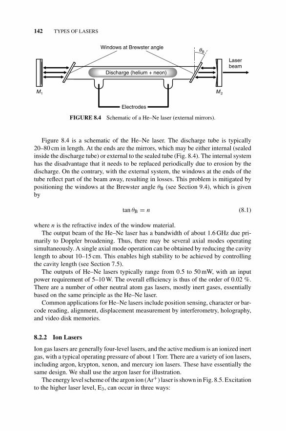
Figure 8.4 is a schematic of the He–Ne laser. The discharge tube is typically20–80 cm in length. At the ends are the mirrors, which may be either internal (sealedinside the discharge tube) or external to the sealed tube (Fig. 8.4). The internal systemhas the disadvantage that it needs to be replaced periodically due to erosion by thedischarge. On the contrary, with the external system, the windows at the ends of thetube reflect part of the beam away, resulting in losses. This problem is mitigated bypositioning the windows at the Brewster angle θB (see Section 9.4), which is givenby
tan θB = n (8.1)
where n is the refractive index of the window material.The output beam of the He–Ne laser has a bandwidth of about 1.6 GHz due pri-
marily to Doppler broadening. Thus, there may be several axial modes operatingsimultaneously. A single axial mode operation can be obtained by reducing the cavitylength to about 10–15 cm. This enables high stability to be achieved by controllingthe cavity length (see Section 7.5).
The outputs of He–Ne lasers typically range from 0.5 to 50 mW, with an inputpower requirement of 5–10 W. The overall efficiency is thus of the order of 0.02 %.There are a number of other neutral atom gas lasers, mostly inert gases, essentiallybased on the same principle as the He–Ne laser.
Common applications for He–Ne lasers include position sensing, character or bar-code reading, alignment, displacement measurement by interferometry, holography,and video disk memories.
8.2.2 Ion Lasers
Ion gas lasers are generally four-level lasers, and the active medium is an ionized inertgas, with a typical operating pressure of about 1 Torr. There are a variety of ion lasers,including argon, krypton, xenon, and mercury ion lasers. These have essentially thesame design. We shall use the argon laser for illustration.
The energy level scheme of the argon ion (Ar+) laser is shown in Fig. 8.5. Excitationto the higher laser level, E3, can occur in three ways:
GAS LASERS 143
E1
Metastablestate
Ar+ ground state
1
E0
E2
E32
3
Ar ground state
0.515 μm0.488 μm
FIGURE 8.5 Energy levels of the Ar+ system.
1. Through collision of (Ar+) ions in their ground state with electrons;
2. Through collision of (Ar+) ions in the metastable state with electrons;
3. Through radiative cascading from higher levels (to the E3 level).
Laser transition occurs between the E3 (higher) and E2 (lower) levels, with thelifetime of the E3 level being about 10−8, which is an order of magnitude greater thanthat of the E2 level (about 10−9), thereby satisfying the condition for CW operation.
Unfortunately, the pumping process involves two stages instead of one. In thefirst stage, the neutral atom is ionized by colliding with an electron in the dischargetube. The ion may then be excited to a higher energy level by another collision with anelectron, in the second stage. Since pumping requires two stages, the pumping process,and therefore the ion laser in general, is inefficient. The efficiency is approximately0.1%. Current densities of around 1000 A/cm2 are therefore required to maintain thethreshold population inversion in ion lasers.
The need for such high-current densities complicates the design of ion lasers. Tobegin with, the tube diameter must remain relatively small to achieve such high-current densities. In addition, the high-current densities necessary for laser operationraise the temperature of the ions in the discharge tube to very high levels (of theorder of 3000 K). This has the effect of broadening the Doppler linewidth to about3.5 GHz (see equation (5.26)). Furthermore, with the ions at such high temperatures,collisions with the tube walls would normally cause significant damage. This damagemight be reduced by increasing the diameter of the tube wall, but that requires higherpumping currents for the same power output. Thus, discharge tubes must be madeof ceramic materials to withstand collisions with the hot ions. Wall damage may be
144 TYPES OF LASERS
Return tube
–+
Discharge
Anode Cathode
θB
M1 M2
FIGURE 8.6 Schematic of an Ar+ laser.
further reduced by applying a static magnetic field along the tube axis in the dischargezone. This is done by wrapping a current-carrying coil around the tube. It forces theelectrons to undergo a spiral motion along the tube axis, thereby confining them tothe tube center, and reducing contact with the walls. This solution also has the benefitof increasing the electron density along the tube center, which increases the pumpingrate and thus the output power.
In addition to raising the temperature of the discharge tube, the high-current densitycauses the ions to migrate toward the cathode. Since the ions have a lower mobilitythan electrons, there is a tendency for the ions to accumulate at the cathode. Thismight result in the discharge being extinguished due to a loss of active medium. Toprevent this from happening, a return path is provided between the anode and thecathode (Fig. 8.6). The return tube is made longer than the discharge tube to preventthe discharge from passing through the return tube (path of least resistance). Overall,the two-stage pumping scheme of ion lasers significantly complicates their designand restricts their performance. Yet, ion lasers have been put to practical use.
Output of the Ar+ ion laser occurs at a number of wavelengths, with the strongestbeing the 0.4881�m (blue) and 0.515�m (green) wavelengths. Power outputs typi-cally range from about 1 to over 20 W CW, but can also be lower than 1 W. Ar+ ionlasers are used in laser printers, in surgery, for pumping dye lasers, and in spectroscopy.Other ion lasers include the krypton (Kr+) ion laser with an output wavelength of0.6471�m and a CW output of 5-6 mW, and the xenon (Xe+) ion laser with an outputwavelength of 0.5395–0.995�m, and a pulsed peak power output of about 200 W.
8.2.3 Metal Vapor Lasers
The design of a metal vapor laser is similar to that of the He–Ne laser, since both useHe to assist the pumping process. However, the metal vapor laser employs a metalvapor instead of a second inert gas. The metal vapor is generated by a metal componentthat is contained in a small reservoir close to the anode, where it is heated to producethe vapor in the discharge tube. The ionized vapor atoms migrate toward the cathode
GAS LASERS 145
where the vapor eventually condenses. This process is referred to as cataphoresis. Anadequate supply of metal is therefore necessary for the life of the laser (about 5000 h).It may also result in coating of a laser mirror with the metal, causing the laser beamto be quenched. The metal vapor lasers are used in facsimiles, spectroscopy, andphotochemical experiments. Typical CW output powers for these lasers fall between50 and 100 mW, filling the range between He–Ne and Ar+ ion lasers.
Several different tube configurations have been designed to prevent the outputwindows from being coated with metal. One example is where the tube is designedwith a second anode between the output window and the cathode. The second anodemaintains a discharge that keeps the metal from approaching the output window(Fig. 8.7.). There are a variety of metal vapor lasers, but the most common ones arethe helium–cadmium (He–Cd) and helium–selenium (He–Se) lasers. In the followingparagraphs, we discuss the He–Cd laser as an example of a metal vapor laser.
Figure 8.8 illustrates the energy level scheme of the He–Cd system. The energylevels of the excited He states, HE3a and HE3b, are much higher than those of theexcited Cd+ ions ((Cd+)∗—combined ionization and excitation energies (CE3)). Col-lision between the excited He atoms (He∗) and Cd atoms in their ground state resultin transfer of energy to the Cd atoms causing their ionization and excitation to thehigher energy level:
He∗ + Cd → He + (Cd+)∗ + e− (8.2)
This mode of energy transfer is called Penning ionization, and is not resonant.Unlike the case of ion lasers, the excitation or pumping process involves a singlestage. As a result, the pump rate is proportional to the current density. The excessenergy is transformed into kinetic energy of the electron that is ejected. The excitedhelium states are metastable, thereby making the energy transfer efficient.
Even though both the CE2 and CE3 states of the Cd+ ion can be excited, the CE3states are more easily excited. Moreover, they have a much longer lifetime (10−7s)than the CE2 states (10−9 s). Population inversion is thus easily achieved between
Heater
CathodeAnode Anode
Cadmium
HeaterCondenser
Discharge
FIGURE 8.7 Metal vapor laser with two anodes. (From Duley, W. W.,1983, Laser Processingand Analysis of Materials. By permission of Springer Science and Business Media.)
146 TYPES OF LASERS
Penningionization
Cd+ ground state
Cadmium
HE0
HE3b
HE3a
CE0
CE1
CE2a
CE3a
Helium
Cd ground stateHe ground state
CE3b
CE2b0.4416 μm
0.325 μm
FIGURE 8.8 Energy levels of the He–Cd system.
the CE2 and CE3 states. Laser transition occurs on the CE3b → CE2a line with awavelength of 0.325�m in the ultraviolet range, and the CE3a → CE2b line with awavelength of 0.4416�m in the blue range. Efficiencies may be up to 0.02 %, whilethe oscillation bandwidths are about 5 GHz.
8.2.4 Molecular Gas Lasers
Unlike the neutral atom and ion gas lasers, molecular gas lasers derive their transitionalenergy from a molecule. The overall energy of a molecule is normally composed offour principal components:
1. Electronic energy, which results from electron motion about each nucleus.
2. Vibrational energy, which results from vibrations of the constituent atoms aboutan equilibrium position.
3. Rotational energy, which results from rotation of the molecule as a whole aboutan axis.
4. Translational energy, which results from linear or curvilinear motion of themolecule as a whole.
Each electronic energy level (Fig. 8.9a), consists of a number of vibrational levels(Fig. 8.9b) and each vibrational level in turn consists of a number of rotational levels(Fig. 8.9c). In Fig. 8.9, E1 refers to the ground level, and E2 refers to the first excitedstate (cf. Fig. 8.19) for the case where the atoms of the molecule are held fixed at anuclear separation distance r. The electronic, vibrational, and rotational energies arequantized, and transitions between the various levels can produce laser oscillations.Translational energy, on the contrary, is not quantized, and is thus not useful forlaser oscillations. There are three common transitions associated with the quantizedenergies. These are normally used to categorize the lasers as
GAS LASERS 147
3
2
1
V = 0′
″
3
2
1
V = 0E1
E
(a) (b) (c)
2
FIGURE 8.9 Energy levels of a molecule. (a) Electronic. (b) Vibrational. (c) Rotational.
1. Vibrational–rotational.
2. Vibronic (vibrational–electronic).
3. Pure rotational.
A fourth type of molecular laser, which falls in a category of its own, but some ofwhich may classify as a vibronic laser, is the excimer laser. In the following sections,we shall discuss the vibrational–rotational, vibronic, and excimer lasers, since theseare more easily produced commercially. Since laser action is relatively difficult toachieve in rotational lasers, these are not further discussed.
8.2.4.1 Vibrational–Rotational Lasers In vibrational-rotational lasers, oscillationis achieved as a result of transitions that occur between vibrational levels (rotationallevel of one vibrational state and the rotational level of another vibrational state) of agiven electronic state, normally the ground state. The wavelength of the output beamis usually in the range 5–300�m (middle to far-infrared).
The CO2 laser is the most common example. It has the advantage of relatively highefficiencies, about 10–30 %. Common applications of the CO2 laser include materialsprocessing, communications, spectroscopy, and surgery.
Figure 8.10 shows the following three fundamental vibration modes of the CO2molecule:
1. Asymmetric stretching.
2. Bending.
3. Symmetric stretching.
The energy level or oscillation behavior of the system is described using the numberof energy quanta in each vibrational mode. For example, (pqr) indicates that thereare p quanta in the symmetric mode, q quanta in the bending mode, and r quanta inthe asymmetric mode.
148 TYPES OF LASERS
Symmetric (n00)ν1 = 4 × 10¹³ Hz
Carbon OxygenOxygen
Bending (0n0)ν2 = 2 × 10¹³ Hz
Asymmetric (00n)ν3 = 7 × 10¹³ Hz
FIGURE 8.10 Vibrational modes of the CO2 molecule.
The active medium for the CO2 laser is a mixture of CO2, N2, and He. The CO2molecule provides the transitions that generate the laser beam. N2 helps to increasethe population of the upper lasing level, while He helps to depopulate the lowerlasing level, thereby enhancing the achievement of population inversion. Since N2 isa diatomic molecule, it has only one vibrational mode, unlike the CO2 molecule. Thecontributions of the individual gases are now further discussed.
The energy level scheme of the electronic ground state for this type of laser isshown in Fig. 8.11. The (001) level of the CO2 molecule, which is the upper lasinglevel, is pumped by the following:
1. Direct electron collision.
2. Resonant energy transfer.
3. Radiationless transition from upper excited levels.
9.6 μm
symmetric BendingN2CO2
10.6 μm
020
010
100
001
000
1
0
Atomiccollisions
Asymmetric
CO2 ground state N2 ground state
FIGURE 8.11 Energy level scheme of the CO2 laser.
GAS LASERS 149
Collision between electrons accelerated in the discharge and the CO2 moleculeresults in the molecule being excited preferentially to the (001) energy level. Thisprocess can be represented as
e− + CO2(000) → e− + CO2(001) (8.3)
With resonant energy transfer, electron collision with an N2 molecule first resultsin the latter being excited from the ground level (0) to the upper level (1). This is a veryefficient process, and since the upper level is a metastable state and has about the sameenergy level as the (001) level of CO2, resonant transfer of energy can occur easilybetween the (1) level of N2 and the (001) level of the CO2 molecule. Finally, higherexcited levels (00r) of CO2 decay rapidly to the metastable (001) state. As a result ofthese various processes, pumping of the (001) level is very efficient, contributing tothe relatively high efficiency (up to 30 %) of the CO2 laser.
The upper lasing level is the (001) level, and the lower levels are the (100) and(020) levels. Transition between the (001) and (100) levels results in oscillation at thewavelength 10.6�m, while that between the (001) and (020) results in oscillation at thewavelength 9.6�m, with the transition at 10.6 �m having a much greater likelihood(about 20 times) of occurring than the 9.6�m transition, since it has a higher gain. The10.6�m output is thus more common. Frequency-selection techniques can be used tosuppress the 10.6�m output if the 9.6�m output is desired.
In reality, each of the vibrational levels mentioned, say (001), is composed ofseveral rotational levels that have a population distribution given by the Boltzmanndistribution. Thus ideally, all the rotational levels would be oscillating. However, onlythe rotational level with highest gain oscillates since the thermalization rate of therotational levels (about 107 s−1 (mmHg)−1) is much greater than the rate at whichthe population of the oscillating rotational level decreases. Thermalization refers toredistribution of the population of various levels to achieve equilibrium or steady-statedistribution.
The lifetimes of the various levels are influenced by the partial pressures of the gasmixture. For a typical mixture with partial pressures of 1.5mmHg for CO2, 1.5 mmHgfor N2, and 12 mmHg for He, the lifetime of the upper lasing level is found to be about0.4 ms. The energy difference between the lower lasing levels (100) and (020) is verysmall, much less than kBT , and thus the (100) → (020) decay is very fast. Likewise,the (100) → (010) and (020) → (010) decays are very fast. Thermal equilibrium isthus reached between the three levels (100), (020), and (010) in a relatively shortperiod. As a result, if the decay from the (010) level to the ground state (000) is notfast enough, then there would be an accumulation of atoms in all three lower levelssince they are in thermal equilibrium. This would lead to a quenching of populationinversion. The decay of the (010) level to the ground state is accelerated or enhancedby the presence of He in the gas mixture. For the partial pressures mentioned, thecorresponding lifetime of the (010), (100), and (020) levels is about 20 �s, thereforesatisfying the condition for laser oscillation.
The presence of He in the mixture serves another purpose. To prevent repopulationof the (010) level and thus lower lasing levels by thermal excitation, the energy
150 TYPES OF LASERS
difference between (010) and the ground state has to be much greater than kBT . Thisoccurs if the temperature of the CO2 gas is kept relatively low. Since He has a highthermal conductivity, it can conduct heat away to the tube walls effectively, therebykeeping the CO2 gas at a low temperature.
The long lifetime of the upper lasing level makes CO2 lasers highly suited to Q-switching. However, the average output power that results from the Q-switched laserof this type is only about 5% of the power available from one that is operated in theCW mode. This results from the fact that the pulse period is of the same order ofmagnitude as the time taken for thermalization of the various rotational levels of thevibrational lasing level. Thus only a small fraction of the rotational levels are able tocontribute to the lasing action.
There are various designs for CO2 lasers, including the following:
1. Sealed tube lasers
2. Longitudinal-flow lasers
3. Transverse-flow lasers
4. Transversely excited atmospheric (TEA) lasers
5. Gas-dynamic lasers.
For the first four types, excitation may be by either radio frequency (rf) or directcurrent (dc) (Section 3.2).
Sealed Tube Lasers In sealed tube lasers, the gas mixture or active medium iscontained in an enclosed chamber (the discharge tube). Therefore, there is no freshsupply of gases or active medium to the laser. In the case of CO2 lasers, dissociationproducts (simpler chemical constituents of larger compounds) that are undesirablefor laser operation may form in the tube. For example, carbon monoxide (CO) formsfrom CO2:
2CO2 → 2CO + O2 (8.4)
The formation of carbon monoxide is undesirable in CO2 lasers, because it absorbslight at 10.6 �m (the main transition wavelength of a CO2 laser). Thus, if a largeamount of dissociation products exist within the discharge tube, the laser may bequenched.
To prevent quenching of laser action due to accumulation of dissociation products,a catalyst is used to regenerate CO2 from CO. There are a number of ways this canbe done:
1. A small amount (about 1 %) of water vapor (H2O) is added to the gas mixture;
2. A Ni cathode that is heated to about 300◦C is used as the catalyst.
With these catalysts, the laser can be used for over 10, 000 h. Typical output powersfor sealed tube lasers are of the order of 60 W/m. The output beam of the sealed tubeCO2 laser normally operates in the low-order mode. Therefore, it has been used in
GAS LASERS 151
M1
Laserbeam
M2
Discharge electrodes
CO2N2He
Discharge
FIGURE 8.12 Schematic of the axial flow CO2 laser.
microsurgery and micromachining where high accuracy of the low-order mode beamis essential. Machining applications include drilling and cutting of thin metal sheets(about 0.5–1.5 mm in steels), and non–metals.
Axial Flow Lasers Figure 8.12 shows the configuration of a typical axial (longitu-dinal) flow CO2 laser, where the gas mixture is made to flow continuously throughthe tube. Continuous flow of the gas mixture is used mainly to enable the dissociationproducts of the discharge, especially CO, to be removed, thereby preventing contam-ination. The cavity mirrors can be either internal or external. For the external system,the windows at each end are configured at the Brewster angle. The tube walls are watercooled to remove heat that is dissipated in the discharge. The pressure of the gas inthe tube is normally kept around 15 mmHg. Broadening of the output laser is thenprimarily due to Doppler broadening, with a linewidth of about 50 MHz, even thoughcollision broadening is also significant. Because of the relatively small linewidth, thesystem can easily be operated in a single longitudinal mode by confining the cavitylength to less than 1 m (see Section 2.2.3.2). For mechanical and thermal stability,the tubes are mounted in an invar rod frame to reduce expansion during operation.There are two types of axial flow lasers:
1. Slow axial flow lasers.
2. Fast axial flow lasers.
slow axial flow lasers In this type of laser, the gas mixture flows at a relativelyslow speed (about 20 L/min), with the prime objective of removing the dissociationproducts. Heat is removed by conduction from the tube center to the walls. The outputpower is typically about 50–60 W/m, or 50–500 W overall, and does not depend onthe tube diameter which is about 25 mm. The higher output powers are obtained byincreasing the optical path length of the beam in the resonator, using folding mirrorsto redirect the beam along different paths (Fig. 8.13). The lower power levels are usedin laser surgery, while the higher powers are more appropriate for scribing, resistortrimming, welding of thin sheets, and cutting nonmetals.
152 TYPES OF LASERS
M2
M1
FIGURE 8.13 One possible resonator configuration.
fast axial flow lasers The output power of axial flow lasers is limited by theheat generation within the laser, and the manner in which it is extracted. Since theefficiency of the laser is up to 30 %, over 70 % of the energy input is dissipated asheat that, in slow axial flow lasers, is removed by diffusion from the tube center tothe walls. Removal of the dissipated heat can be made more efficient by flowing thegas mixture through the tube at much higher speeds of about 300–500 m/s to carryaway the heat by convection. The gas is then recycled through a heat exchanger. Thisenables the power to be greatly increased to about 600 W/m, or 500 W to 6 kW inoverall power output and units as large as 20 kW have been built. This is a fast axialflow laser. Axial flow lasers are extensively used in materials processing, for example,welding and cutting. They tend to have better beam characteristics than transverseflow lasers described in the following section.
transverse flow lasers In transverse flow lasers, the gas flow, electrical dischargeor current flow, and resonator axis are mutually perpendicular to one another (Fig.8.14a and b). This is because the heat generated within the discharge tube can be moreefficiently extracted by flowing the gas at a rate of about 60 m/s in a direction normalto the resonator axis. This results in a reduced operating temperature, and undersuch circumstances, the laser can be operated at higher pressures. But the outputpower for CO2 lasers increases with the pressure. Thus, for a given discharge currentdensity, higher output powers are achieved by increasing the total pressure from 15to 100 mmHg. However, the electric field required to maintain the discharge at thehigher pressures also increases to very high levels of about 500 kV/m. For standardaxial flow lasers of cavity length 1 m or more, the amount of voltage required wouldbe impractical. To circumvent this, the discharge is applied normal to the resonatoraxis so that the distance between the electrodes is as small as possible, of the orderof 10 mm. This is also sometimes referred to as a transversely excited (TE) laser.
There are two principal ways in which the discharge is sustained in transverse flowlasers.
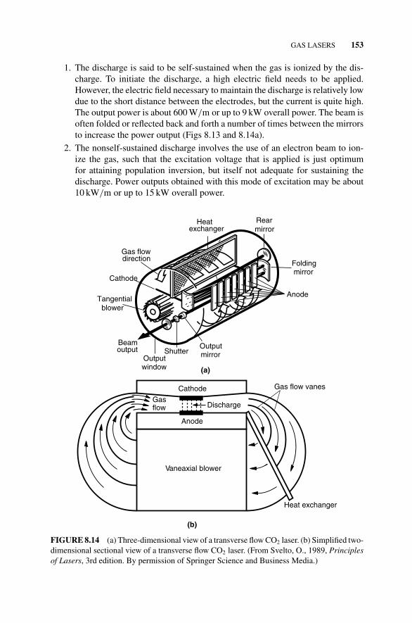
GAS LASERS 153
1. The discharge is said to be self-sustained when the gas is ionized by the dis-charge. To initiate the discharge, a high electric field needs to be applied.However, the electric field necessary to maintain the discharge is relatively lowdue to the short distance between the electrodes, but the current is quite high.The output power is about 600 W/m or up to 9 kW overall power. The beam isoften folded or reflected back and forth a number of times between the mirrorsto increase the power output (Figs 8.13 and 8.14a).
2. The nonself-sustained discharge involves the use of an electron beam to ion-ize the gas, such that the excitation voltage that is applied is just optimumfor attaining population inversion, but itself not adequate for sustaining thedischarge. Power outputs obtained with this mode of excitation may be about10 kW/m or up to 15 kW overall power.
Anode
Foldingmirror
Rearmirror
Heatexchanger
Gas flowdirection
Tangentialblower
Cathode
Outputmirror
(a)
Outputwindow
ShutterBeamoutput
Cathode
Anode
Vaneaxial blower
Heat exchanger
(b)
Gas flow vanes
Gasflow Discharge
FIGURE 8.14 (a) Three-dimensional view of a transverse flow CO2 laser. (b) Simplified two-dimensional sectional view of a transverse flow CO2 laser. (From Svelto, O., 1989, Principlesof Lasers, 3rd edition. By permission of Springer Science and Business Media.)
154 TYPES OF LASERS
The high powers attainable from transverse flow lasers make them highly suitablefor materials processing applications such as welding, surface heat treatment, andcladding.
Transversely Excited Atmospheric Pressure Lasers Since the output power of theCO2 laser increases with operating pressure, the power output of the transverselyexcited laser is significantly increased if it is made to operate at atmospheric pressure.This is the TEA pressure laser. Unfortunately, in the CW mode, glow dischargeinstabilities develop, causing arcing in the discharge, when the laser is operated atatmospheric pressure. The instability is prevented by pulsing the electric field thatis applied to the electrodes. For a short enough pulsing period, of the order of amicrosecond, there is no time for the instability to fully develop, resulting in a pulsedoutput beam with a peak power of up to 20 TW. The potential for arc formation maybe further reduced by preionizing the gas mixture just before applying the voltagepulse. This may involve the use of a trigger electrode that applies a high-voltagetrigger pulse to ionize the mixture in a localized area, or it may involve the use of apulsed electron beam. When the gas mixture is sealed, low pulse rates of about 1 Hzare obtained, while rates of about 1 kHz are obtained when it is transversely flowed.
The linewidths, due mainly to collision broadening at atmospheric pressure, arerelatively broad, of the order of 4 GHz, making it suitable for achieving even shorterpulse duration (about 1 ns) by mode-locking. TEA CO2 lasers are often used in laserfusion experiments, and also in pulsed laser marking.
Gas-Dynamic Lasers The principle of the gas-dynamic laser is based on the changein state of a gas as it undergoes adiabatic expansion. When a gas mixture is initiallykept at a high temperature and pressure (about 1400 K and 17 atm, respectively) thepopulation distribution given by the Boltzmann distribution law at that temperatureand pressure is such that the population of the upper lasing level (001) is relativelyhigh, about 10% that of the ground level. However, that of the lower lasing level, (100),is still higher, about 25%, so that there is no population inversion. If, however, themixture is now made to undergo adiabatic expansion through a nozzle, the temperatureof the gas is significantly reduced downstream of the nozzle. This redistributes thepopulations to the equilibrium level equivalent to the corresponding temperature at anydownstream location. Even though both the upper and lower lasing level populationswill be reduced, the shorter lifetime of the lower lasing level will result in its populationbeing reduced sooner (at a location closer to the nozzle) than that of the upper lasinglevel. Consequently, there will be a significant region downstream of the nozzle wherea population inversion will exist (Fig. 8.15a).
There are two conditions that need to be satisfied for a population inversion to bepossible:
1. The period over which there is a reduction in pressure and temperature duringexpansion has to be smaller than the lifetime of the upper lasing level. Thisrequires expansion to very high downstream velocities.
2. The period has to be longer than the lifetime of the lower lasing level.
GAS LASERS 155
0.15
0–10 50
Distance from throat (cm)(a)
0.25
0.10
0.05
403020100
0.20NN000
Lower Level
Upper Level
T = 1400 KP = 17 atm7.5% CO291.3% N21.2% H2O
T = 354 KP = 0.086 atm
Subsonicregion
Active region(L = 20 cm)
Throat height 0.8 mm
Expansion region
Expansionnozzles
Mirror
Mirror
(b)
L = 20 cm
3 cm
30 cm
FIGURE 8.15 (a) Gas-dynamic CO2 laser principle. (b) Schematic of a gas-dynamic CO2
laser. (From Svelto, O., 1989, Principles of Lasers, 3rd edition. By permission of SpringerScience and Business Media.)
The lifetime of the lower lasing level can be further reduced by the addition of smallamounts of water vapor at the nozzle exit. This increases the population inversion. Thecavity mirrors are mounted in the downstream region where most of the populationinversion occurs (Fig. 8.15b). Power outputs of up to 80 kW have been produced, anddue to the high energy involved, can only be used for short periods in the CW mode. Adisadvantage of this type of laser is the size and noise associated with the lasing action.
8.2.4.2 Vibronic Lasers As the name implies, oscillation is achieved in vibroniclasers as a result of transitions between different electronic states (vibrational level ofone electronic state and the vibrational level of another electronic state). A commonexample is the nitrogen (N2) laser with an output wavelength of 0.3371�m in theultraviolet range. Another type of vibronic laser is the hydrogen (H2) laser withoutput wavelengths of 0.160 and 0.116�m in the vacuum ultraviolet range. At suchlow wavelengths, the threshold power increases rapidly with decreasing wavelength,making it difficult to achieve laser oscillation.
156 TYPES OF LASERS
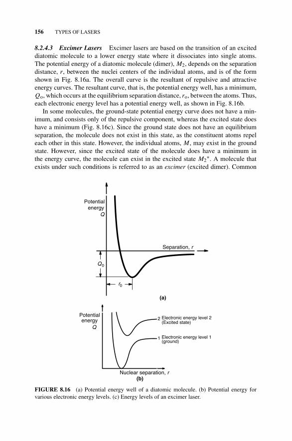
8.2.4.3 Excimer Lasers Excimer lasers are based on the transition of an exciteddiatomic molecule to a lower energy state where it dissociates into single atoms.The potential energy of a diatomic molecule (dimer), M2, depends on the separationdistance, r, between the nuclei centers of the individual atoms, and is of the formshown in Fig. 8.16a. The overall curve is the resultant of repulsive and attractiveenergy curves. The resultant curve, that is, the potential energy well, has a minimum,Qo, which occurs at the equilibrium separation distance, ro, between the atoms. Thus,each electronic energy level has a potential energy well, as shown in Fig. 8.16b.
In some molecules, the ground-state potential energy curve does not have a min-imum, and consists only of the repulsive component, whereas the excited state doeshave a minimum (Fig. 8.16c). Since the ground state does not have an equilibriumseparation, the molecule does not exist in this state, as the constituent atoms repeleach other in this state. However, the individual atoms, M, may exist in the groundstate. However, since the excited state of the molecule does have a minimum inthe energy curve, the molecule can exist in the excited state M2
∗. A molecule thatexists under such conditions is referred to as an excimer (excited dimer). Common
r0
Potentialenergy
Q
Q0
Separation, r
(a)
Nuclear separation, r(b)
Potentialenergy
Q
2
1
Electronic energy level 2(Excited state)
Electronic energy level 1(ground)
FIGURE 8.16 (a) Potential energy well of a diatomic molecule. (b) Potential energy forvarious electronic energy levels. (c) Energy levels of an excimer laser.
GAS LASERS 157
Transition
Nuclear separation, r
Potentialenergy Excited state
Ground state
(c)
FIGURE 8.16 (Continued)
examples are the noble gases (Ar2∗, Kr2
∗, Xe2∗) or their oxides, (e.g., ArO∗), or
halides (e.g., ArF∗). The noble gas halide excimer lasers tend to have better beamproperties than the pure noble gas excimer lasers.
For such a material, the excimer corresponds to the upper lasing level, while the freeatoms represent the lower lasing level. Transition occurs between different electronicstates. Thus when the molecule undergoes a transition from the upper (excimer state)to the lower lasing level (ground state), it dissociates into individual atoms. As aresult, the ground state of the molecule is always empty, making it easier to achievepopulation inversion. The transition is broadband since there are no well definedvibrational–rotational transitions. The resulting output laser beam is thus tunableover a range of wavelengths.
Pumping may involve subjecting the noble gas to a pressure of about 10 atm andusing an electron beam or an electrical discharge to excite it to the higher level,where the atoms combine to form the excited M2
∗ excimer. For the Xe2∗ excimer,
transition occurs at a wavelength of 0.172�m with a linewidth of �λ = 0.015 �m,over which the laser beam is tunable, while the output wavelength of the Ar2
∗ excimerlaser is about 0.125�m. The noble gas halide excimer lasers also generate beams inthe ultraviolet range. Examples include ArF, 0.193�m; KrF, 0.248�m; XeCl,0.308�m; and XeF, 0.351�m. The linewidth of the ArF excimer laser, for example,is about �λ = 500 pm. This can be reduced to about �λ = 1 pm1 using wavelengthdispersive optical elements in the laser cavity.
The output beam is normally pulsed with a pulse duration of about 10 ns, averageoutput power of up to 200 W, and a pulse rate of up to 1 kHz. The efficiency of the
1 http://www.excimers.com/Narrowband.htm
158 TYPES OF LASERS
laser is about 1 %. Excimer lasers are useful in applications such as isotope separationwhere the ultraviolet output is very useful. XeCl excimer lasers have been used inlaser-assisted chemical vapor deposition for semiconductor manufacture. Generally,excimer lasers are useful for removal processes such as photochemical reactions, ormore specifically, photoablation, and are typically used for polymers, ceramics, andglass. One application involves making holes in the nozzles of ink jet components forprinters. Other applications include wire stripping and burr removal. In recent years,they have also been gaining increasing importance in materials processing.
8.3 DYE LASERS
The dye laser is a form of liquid laser where the active medium is an organic dye,which is solid that is dissolved in a solvent such as water, ethyl alcohol, or methylalcohol. Various dyes are used, including scintillator dyes with wavelengths lessthan 0.4 �m; coumarin dyes with wavelengths in the range 0.4–0.5 �m; xanthenedyes (e.g., rhodamine 6 G) from 0.5–0.7 �m; and polymethine dyes in the range0.7–1.0 �m.
The energy level scheme of a typical dye laser is illustrated in Fig. 8.17. Thereare two types of states in the energy level structure of lasing dyes. One is the singletstate, indicated by Si, where the total spin of the electrons in each level is zero. Theother is the triplet state Ti with a total spin of 1. Each electronic energy level ofeither state consists of a number of vibrational levels, with each vibrational level inturn consisting of a number of rotational levels. The energy difference between thevibrational levels is of the order of 1500/cm, while that between the rotational levels is
S2
SingletTotal spin = 0
S1
S0
T2
T1
TripletTotal spin = 1
Absorbingtransition
Spinchange
Ground
FIGURE 8.17 Energy levels of a dye laser.
DYE LASERS 159
Absorption
Wavelength (nm)
Fluorescence
Amplitude
FIGURE 8.18 Fluorescence in a dye laser.
about 15/cm, which is relatively small.2 The rotational levels thus essentially overlap.This overlap, when coupled with line broadening, results in electronic energy levelsthat are broadband or almost continuous from one vibrational level to another.
Pumping results in excitation of the dye molecule from the ground level S0 toa vibrational level in the next electronic level, S1. Radiative transitions between S
and T levels, that is, singlet–triplet transitions, are forbidden, since selection rulesindicate that the total spin of an atom or molecule cannot change during a transition(see Section 1.2.1). Thus, pumping can only excite the molecule to the S1 level orhigher. Due to the continuous nature of the electronic energy levels, absorption canoccur over a broadband. After excitation to a vibrational level of S1, the moleculeundergoes a nonradiative transition to the lowest vibrational level of S1. The lifetimefor this transition is of the order of 1 ps. In reality, it is thermalization of the S1level that occurs. This results in the lowest vibrational level of the S1 state beingeffectively populated, and laser transition then occurs between this level and any ofthe vibrational levels of S0, from which the molecule undergoes another very fastnonradiative transition, also with a lifetime of about 1 ps, to the lowest vibrationallevel of S0. The latter nonradiative transition also effectively depopulates the lowerlasing level. By comparison, the lifetime of the laser transition from S1 to S0 is of theorder of 1 ns. These are the reasons why lasing action occurs from what might appearto be a two-level system. Since absorption occurs between the lowest S0 vibrationallevel and any S1, while lasing occurs between the lowest S1 level and any S0 level, theabsorption and emission wavelengths are usually different, with the latter being longer(Fig. 8.18). This is termed fluorescence, where light is absorbed at one frequency andre-emitted at another frequency. Since lasing action can result from transition betweena number of vibrational levels, the resulting emission spectrum is very broad.
Even though the triplet Ti states are not directly involved in lasing action, theydo have significant influence on the process, essentially limiting laser action. This is
2 When frequency is expressed in units of cm−1, the actual frequency is obtained by multiplying the numberby the velocity of light in vacuum (3 × 1010 cm/s). The corresponding energy is obtained by multiplyingthe frequency by Planck’s constant (see equation (1.2)).
160 TYPES OF LASERS
due to the fact that intermolecular collisions can result in a transition from state S1to T1. This is referred to as intersystem crossing, and reduces the population of theupper lasing level S1. Furthermore, transition from T1 to S0, which is referred to asphosphorescence, is forbidden radiatively, but may also occur by collision. However,if its lifetime is longer than the lifetime for intersystem crossing, then accumulationof molecules in level T1 will result. Now transition from T1 to T2 is allowed, andoccurs in a wavelength range that corresponds to the lasing transition wavelengthrange, S1 to S0. The absorption associated with the T1 → T2 transition results in aloss in laser gain, and can quench laser action after pumping has progressed for sometime. Thus, pumping sources with very fast rise times, short relative to the time ittakes for molecules to accumulate in level T1 to an appreciable degree, are necessaryfor good lasing action. The lifetime of the triplet state T1 can be reduced from about10−3 s. to about 10−7 s. by the addition of oxygen to the dye solution. This has theeffect of reducing the accumulation of molecules in state T1, thus minimizing thequenching effect of the T1 level. Either short-pulsed lasers, for example, the N2 laser,or flashlamps with very fast rise times are used as pumping sources.
The broad output of each dye enables the resulting laser to be tuned over a widefrequency range, about 50 nm wavelength range. This can be done using wavelength-selecting devices such as a diffraction grating unit or a dispersive prism. The use of alarge variety of dyes, which are automatically interchanged further enables tuning tobe extended over an even broader range of frequencies from near-ultraviolet, throughnear-infrared. However, the dyes have a tendency to degrade, and often require acomplex liquid-handling system.
The CW output power of dye lasers is of the order of 10–100 mW, while thepulsed outputs may average about 100 W with peak powers of about 1 kW. The broadoscillation bandwidth enables the output of dye lasers to be mode locked to producevery short pulses of the order of picoseconds. The tunable characteristics of dyelasers make them very useful for spectroscopy, pollution detection, photochemicalprocessing, and isotope separation.
Tunable solid-state lasers are easier to operate, and also generate output powersin comparison with dye lasers. Furthermore, they do not involve the use of toxicmaterials that may pose significant disposal problems. On the contrary, dye lasers canbe tuned over a wider range of the electromagnetic spectrum, and are also capable ofgenerating much shorter pulses.
8.4 SEMICONDUCTOR (DIODE) LASERS
Semiconductor lasers, also known as diode lasers, are based on the generation ofphotons when electrons in the conduction band of an appropriate semiconductormaterial recombine with holes in its valence band. The discussion in this sectionstarts with a background on semiconductor materials in general. This is followedby the basic principles of semiconductor lasers, and finally the different types ofsemiconductor lasers.
SEMICONDUCTOR (DIODE) LASERS 161
8.4.1 Semiconductor Background
As discussed in Sections 1.1 and 1.2, electrons in an atom can only occupy specificquantum states, and the distribution of electrons in the atom depends on the temper-ature. In semiconductors, it is more appropriate to consider the energy levels of theentire solid rather than individual atoms. This is because the available energy levelsfor electrons in these solids can be grouped into two broad bands, where the energylevels within each band are so closely spaced that they essentially overlap. These arethe following:
1. The valence band where the energy levels are almost completely filled byelectrons such that the electrons are not freely mobile in the solid.
2. The conduction band where the energy levels are either empty or partiallyoccupied by electrons that are able to move freely within the solid (Fig. 8.19).
The energy separation between these two bands is referred to as the bandgap orforbidden band, and cannot be occupied by electrons in the solid.
The energy levels in the valence and conduction bands are described by Fermi–Dirac statistics where the probability, p(E), of occupation of an energy level is givenby
p(E) = 1
1 + e
(E−FekBT
) (8.5)
where E is the energy of the level of interest, Fe is the energy of the Fermi level, kBis Boltzmann’s constant, and T is the absolute temperature.
Conduction band, C
(a)
b
Valence band, V b
Forbiddenband, Eg
Fe
Conduction band,
(b)
C bValence band, Vb
Fe
Fe
Conduction band, Cb
Valence band, Vb
Forbidden band,
(c)
Eg
FIGURE 8.19 Energy bands of (a) insulators, (b) metals, and (c) semiconductors. (FromO’Shea, D. C., Callen, W. R., and Rhodes, W. T., 1977 Introduction to Lasers and TheirApplications. Reprinted by permission of Pearson Education, Inc.)
162 TYPES OF LASERS
The Fermi energy defines the energy level where the probability that an electronwill be in that state (i.e., the probability of occupation) is 0.5. From this equation it isfound that at absolute zero,
p(E) ={
0 for E > Fe,
1 for E < Fe.(8.6)
At absolute zero temperature, the electrons occupy the lowest possible energylevels allowed, with all lower energy levels being completely filled before the nextlevel is occupied. Under these conditions, the valence band is completely occupiedwhile the conduction band is empty, and the boundary between them is the Fermienergy level. The material is then an insulator (Fig. 8.19a). This is because conductionof current results from flow of electrons from one level in a band to another level ina band, when the material is subjected to an electric field. With the valence bandbeing completely occupied, then, the electron has no place to go since all levels thatit could occupy are already filled, and the energy required to cross the forbidden gap,Eg and reach the conduction band is much greater than the available thermal energy,that is, Eg >> kBT . However, in good electrical conductors such as metals, eitherthe conduction band is filled to some extent or there is an overlap between it and thevalence band (Fig. 8.19b). There are then empty levels available for electrons to moveinto when the material is subjected to a voltage source. The material is classified asa semiconductor if the forbidden gap is small enough that electrons can be thermallyexcited from the valence to the conduction band, that is, Eg ≈ kBT (Fig. 8.19c). Thematerial’s conductivity then lies in between that of a good conductor and an insulator.
When an electron is raised from the valence band into the conduction band, a holeis created in the valence band (Fig. 8.20). This has essentially the same characteristicsas an electron, except that it has an opposite, that is, positive, charge. The hole alsomoves when subjected to an electric field. In fact, when a voltage is applied to thematerial, holes will flow toward the negative terminal, while electrons flow towardthe positive terminal.
+
– –
– –+
–––
–
Cb
Vb
Eg
–
–
–
––
–
–
–
Eg
C
(a) (b)
b
Vb
FIGURE 8.20 Creation of holes in a valence band. (a) Filled valence band. (b) Partiallyoccupied conduction band with holes in valence band.
SEMICONDUCTOR (DIODE) LASERS 163
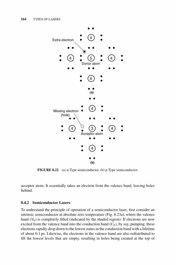
A pure semiconductor that contains no impurities is referred to as an intrinsicsemiconductor. Such a semiconductor has an equal number of conduction electronsand holes since the holes are created by the excitation of electrons to the conductionband. The number of holes in the valence band, and electrons in the conduction band(which are available for electrical conduction), increases with temperature since occu-pation of higher energy levels increases with temperature, according to Boltzmann’slaw. Thus, the conductivity of such materials increases with temperature (the oppositeis true of metals). Examples of such class of materials are silicon and germanium,which are group IV elements of the periodic table, and each has four electrons inthe outermost orbits of their atoms. Each atom shares its four outermost electronswith four other surrounding atoms to form covalent bonds (Fig. 8.21), and since eachbond involves two electrons, the outermost shell now has eight electrons altogetherand is thus completely filled. It thus behaves as an insulator at absolute zero, with theconductivity increasing with temperature.
If now a group V element, say arsenic, which has five valence electrons, is addedin small amounts as impurities to the germanium solid (a process called doping),four of its electrons will form stable bonds with the surrounding germanium atomsleaving the fifth atom not tightly bound and thus essentially free and mobile in thesolid (Fig. 8.22a). When a semiconductor is doped in this manner, it is said to ben-type, where the “n” indicates negative since there is an excess of electrons availablefor conduction. Arsenic is then a donor element. On the contrary, if the original solidis doped with a group III element, say gallium, which has three valence electrons,then there is a deficiency in bonding electrons, resulting in the creation of holes (Fig.8.22b). The resulting semiconductor is said to be p-type. The gallium atom is then an
Covalent
bonds
Si
Si
Si
Si
FIGURE 8.21 Covalent bonding in an intrinsic semiconductor.
acceptor atom. It essentially takes an electron from the valence band, leaving holesbehind.
8.4.2 Semiconductor Lasers
To understand the principle of operation of a semiconductor laser, first consider anintrinsic semiconductor at absolute zero temperature (Fig. 8.23a), where the valenceband (Vb) is completely filled (indicated by the shaded region). If electrons are nowexcited from the valence band into the conduction band (Cb), by say, pumping, theseelectrons rapidly drop down to the lowest states in the conduction band with a lifetimeof about 0.1 ps. Likewise, the electrons in the valence band are also redistributed tofill the lowest levels that are empty, resulting in holes being created at the top of
SEMICONDUCTOR (DIODE) LASERS 165
C
(a)
b
Vb
Eg
C
(b)
b
Vb
Fc
Fv
hpν
Eg
FIGURE 8.23 Basic concepts in semiconductor laser operation. (a) A completely filled va-lence band. (b) A population inversion resulting from a partially filled conduction band. (FromSvelto, O., 1989, Principles of Lasers, 3rd edition. By permission of Springer Science andBusiness Media.)
the valence band (Fig. 8.23b). Under these circumstances, the semiconductor as awhole is not in thermal equilibrium, even though the redistribution process results inlocalized equilibrium in each band. Within each band, there is a quasi-Fermi level thatseparates the fully occupied and empty levels in that band. These are indicated by Fcand Fv for the conduction and valence bands, respectively, and their values dependon the number of electrons pumped to the conduction band. When the semiconductoras a whole is in equilibrium, Fc = Fv.
166 TYPES OF LASERS
With the bottom of the conduction band being occupied by electrons while thetop of the valence band contains holes, a population inversion then exists betweenthe conduction and valence bands (Fig. 8.23b). When the electrons in the conductionband drop down into the valence band and recombine with the holes, either a photon(light wave) or a phonon (thermal wave) will be emitted depending on the material.In materials such as silicon and germanium where the radiation is emitted in the formof heat (phonons), no laser action can be obtained. Laser action can be achieved inmaterials like gallium arsenide where the radiation is in the form of light (photons).
The probability of occupation of any energy level, E, of each band is given by arelationship similar to equation (8.5), with that for the conduction band, pc(E), being
pc(E) = 1
1 + e
(E−FckBT
) (8.7)
while that for the valence band, pv(E), is
pv(E) = 1
1 + e
(E−FvkBT
) (8.8)
During pumping from energy level Ev in the valence band to energy level Ec inthe conduction band, the rate of absorption depends on the following:
1. The density of incident radiation, e(ν)
2. The transition coefficient, B
3. The probability that the valence band energy level is occupied, pv(Ev)
4. The probability that the conduction band energy level is empty, 1 − pc(Ec),
It is therefore given by
dN1
dt= kcBpv(Ev)[1 − pc(Ec)]e(ν) (8.9)
where kc is a constant. Likewise, the rate of stimulated emission is given by
dN2
dt= kcBpc(Ec)[1 − pv(Ev)]e(ν) (8.10)
Here, N1 and N2 are the number of photons absorbed and emitted, respectively.Laser amplification will prevail only when dN2
dt> dN1
dt, that is,
pc(Ec)[1 − pv(Ev)] > pv(Ev)[1 − pc(Ec)] (8.11)
Substituting for pc(E) and pv(E) from equations (8.7) and (8.8) gives
Fc − Fv > Ec − Ev = hpν (8.12)
SEMICONDUCTOR (DIODE) LASERS 167
n-Typep-Type
FIGURE 8.24 p–n Junction diode (forward bias).
where ν is the emitted photon frequency, while Ec and Ev are the upper and lowerlaser levels, corresponding to energy levels in the conduction and valence bands,respectively.
When an electron undergoes a transition from an energy level Ec in the conductionband to an energy level Ev in the valence band, the energy associated with the transitionis also greater than the energy gap, Eg. Thus,
Fc − Fv > hpν = hpc
λ> Eg (8.13)
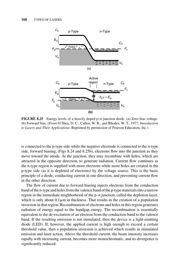
Laser action is more easily achieved in a semiconductor when using a p-n junctiondiode (Fig. 8.24), which is obtained by joining an n-type to a p-type semiconductor.The energy levels for a diode are shown in Fig. 8.25. The energy levels of the con-duction and valence bands are different on the two sides of the junction, with thosefor the n-type being at a lower level than those for the p-type, Fig. 8.25a. Populationinversion is achieved if the diode is heavily doped with acceptors and donors. Undersuch circumstances, the Fermi level Fn for the n-type lies in the conduction band,while that for the p-type Fp lies in the valence band (Fig. 8.25a). A portion of theconduction band in the n-type region is then occupied by electrons up to Fn, and inthe p-type region, holes are added by the acceptors down to Fp.
When there is no voltage applied across the junction, excess electrons flow fromthe n-type to the p-type, setting up an electric field that opposes and thus stops theflow. The Fermi levels on the two sides of the junction, Fn and Fp, are then at thesame level or have the same energy (Fig. 8.25a). The energy levels Ec and Ev in Fig.8.25 indicate the lower level of the conduction band and upper level of the valenceband, respectively.
If the junction is reverse biased by connecting the n-type portion of the junction toa positive electrode and the p-type portion to a negative electrode, the electrons flowtoward the anode while the holes flow toward the cathode, until there are no more freeelectrons available. Current flow then stops. On the contrary, if the positive electrode
168 TYPES OF LASERS
Holes
p-Type n-Type
(a)
FnFp
Cb
Vb
EgCb
Vb
Fn
Fp
p-Type n-Type
Holes
Active
(b)
region
hpν = Eg
Cb
Vb
Eg
Cb
Vb
FIGURE 8.25 Energy levels of a heavily doped p–n junction diode. (a) Zero bias voltage.(b) Forward bias. (From O’Shea, D. C., Callen, W. R., and Rhodes, W. T., 1977, Introductionto Lasers and Their Applications. Reprinted by permission of Pearson Education, Inc.)
is connected to the p-type side while the negative electrode is connected to the n-typeside, forward biasing, (Figs 8.24 and 8.25b), electrons flow into the junction as theymove toward the anode. At the junction, they may recombine with holes, which areattracted in the opposite direction, to generate radiation. Current flow continues asthe n-type region is supplied with more electrons while more holes are created in thep-type side (as it is depleted of electrons) by the voltage source. This is the basicprinciple of a diode, conducting current in one direction, and preventing current flowin the other direction.
The flow of current due to forward biasing injects electrons from the conductionband of the n-type and holes from the valence band of the p-type materials into a narrowregion in the immediate neighborhood of the p–n junction, called the depletion layer,which is only about 0.1�m in thickness. That results in the creation of a populationinversion in that region. Recombination of electrons and holes in this region generatesradiation of energy equal to the bandgap energy. The recombination is essentiallyequivalent to the de-excitation of an electron from the conduction band to the valenceband. If the resulting emission is not stimulated, then the device is a light-emittingdiode (LED). If, however, the applied current is high enough to exceed a certainthreshold value, then a population inversion is achieved which results in stimulatedemission and laser action. Above the threshold current, the beam intensity increasesrapidly with increasing current, becomes more monochromatic, and its divergence issignificantly reduced.
SEMICONDUCTOR (DIODE) LASERS 169
Normally, laser oscillation involves using two mirrors to form a cavity. In semi-conductor lasers, this is achieved by cleavage of the material along natural crys-talline planes to obtain highly reflecting and parallel surfaces at two ends of thecrystal which are also perpendicular to the junction. The other two surfaces are leftrough to suppress oscillation in undesired directions. Furthermore, since semicon-ductors have a very high index of refraction, about 3.6, the inherent reflectivity at thecrystal–air interface is very high, about 35 %, making it unnecessary to use reflectingcoatings.
Semiconductor lasers have the advantage of being relatively small in size and easyto fabricate by mass production, thereby being low cost. Typical dimensions are 1mm × 1 mm × 200�m, with the thickness of the active region, where most of theoscillation is concentrated, being about 1�m (Fig. 8.26). However, due to diffraction,the beam itself is much wider, about 40�m, extending away from the interface into thep- and n- regions. The extension of the beam into the regions away from the interfaceresults in high cavity losses since absorption is much greater than emission as onemoves away from the interface. These losses result in high threshold current densitiesbeing required for laser oscillation.
The threshold current increases with temperature and this is because pv(Ev)[1 − pc(Ec)] increases, and pc(Ec)[1 − pv(Ev)] decreases as temperature increases,and from equation (8.11), that means the oscillation gain decreases with increasingtemperature. The relatively narrow width of the beam, about 40�m, as it comes outof the optical cavity, results in high beam divergence, compared to other lasers, asit is diffracted at the cavity aperture. This may range from 5◦ to 15◦. Also, sincetransition occurs between two broad bands, its monochromaticity is not as good as inother lasers. The direct conversion of electrical energy into optical energy, however,results in very high efficiencies for semiconductor lasers, up to about 50 %. The output
Roughsurfaces
Cleavedsurfaces
–
+
100–300μm
1 mm
1 mm
p
n
Laserbeam
FIGURE 8.26 Schematic of a semiconductor laser.
170 TYPES OF LASERS
wavelengths range from 0.7 to 30�m in the infrared region. Semiconductor lasers areparticularly suited to optical fiber communications.
8.4.3 Semiconductor Laser Types
There are several forms of semiconductor lasers. These include the following:
In the following sections, we shall provide highlights of the first three types thatare listed above.
8.4.3.1 Homojunction Lasers Homojunction lasers are made out of a single semi-conductor material such as gallium arsenide, GaAs. In such lasers, the high concen-tration of electrons and holes in the active region increases the refractive index ofthe material in that region. This results in the emitted light being internally reflectedand thus confined to that region. However, the amount that is lost out of the regionis significant enough to require high threshold current densities for oscillation. Forexample, the threshold current density at room temperature for GaAs is about 105
A/cm2. Thus, homojunction lasers require cryogenic temperature environment forCW operation. At room temperatures, they can only be operated in pulsed mode. Atliquid nitrogen temperature of about 77K, the GaAs laser can be operated under CWconditions. The output wavelength at room temperature is about 0.9�m, decreasingto 0.84�m at 77K, and can thus be tuned by varying the temperature.
8.4.3.2 Heterojunction Lasers Heterojunction lasers are made out of two or morematerials. This significantly reduces the threshold current density to the extent that forsome material combinations, CW operation can be achieved at room temperature. Thisis because the different materials used have different refractive indices and bandgaps.These differences cause radiation generated in the junction region to be reflected backinto the region, resulting in higher efficiency. The difference in bandgap results in thecarriers being confined to the junction region, and this reduces the threshold currentdensity.
Heterojunction lasers can be one of two forms:
1. Single heterojunction.
2. Double heterojunction.
SEMICONDUCTOR (DIODE) LASERS 171
Laserbeam
Contact–
(a)
p-Type
GaAs p-Type
p/n-Type
n-Type
GaAs
Alx Ga1–x As
Alx Ga1–x As
GaAssubstrate
n-Type
Activeregion 0.5 μm
Active Region np
p-TypeAlx Ga1–x As
p-TypeGaAs n-Type
Alx Ga1–x As
p – pheterojunction
n – pheterojunction
(b)
C b
Vb
Cb
Vb
FIGURE 8.27 (a) Schematic of a double heterojunction laser. (b) Energy level scheme of adouble heterojunction laser. (From Luxon, J. T., and Parker, D. E., 1985, Industrial Lasers andTheir Applications, Prentice Hall, Englewood Cliffs, NJ.)
In a single heterojunction, the junction is formed between say, a p-typeAlxGa1−xAs semiconductor and an n-type GaAs semiconductor, where x is a fraction.A typical double heterojunction has an active region of p-type GaAs which is a thinlayer of about 0.1-0.5 �m, sandwiched between an n-type and a p-type AlxGa1−xAs
semiconductor (Fig. 8.27a). There are thus two junctions between different materi-als. This reduces the threshold current density to about 103 A/cm2, enabling roomtemperature CW operation to be achieved. This is due to a number of reasons.
(1) The difference in refractive indices of the materials (being about 3.4 forAlxGa1−xAs and about 3.6 for GaAs) confines the laser to the GaAs activeregion where there is high gain, thereby reducing losses due to absorption.
172 TYPES OF LASERS
(2) The energy gap in the AlxGa1−xAs semiconductor is greater than that in theGaAs semiconductor (Fig. 8.27b). This acts as an energy barrier that reflectsboth holes and electrons back into the active region where they are confined,increasing their concentration and thus, gain in that region.
Since the output wavelength depends on the fraction x of Al in the semiconductor,the oscillation wavelength can be tuned by varying x. Peak pulse powers of 10–20 Wcan be obtained at room temperature with a pulse repetition rate of about 104 Hz,and a pulse duration of the order of a picosecond. Output powers of 5–100 mW canbe achieved at room temperature under CW operation, but 5–10 mW is typical.
8.4.3.3 Quantum Well Lasers If the potential energy well of Fig. 8.16a becomesso narrow that it confines the motion of electrons or holes to two dimensions (planarmotion), then we have a quantum well. Confining motion to one dimension results ina quantum wire, and a quantum dot is obtained when motion is restricted in all threedimensions. The structure of the quantum well laser is similar to the heterojunctionlaser illustrated in Fig. 8.27a, except that with the quantum well laser, the middlelayer is made thin enough to confine electron motion in this region to two dimensions.This improves the efficiency of the laser. Further improvements in efficiency can beobtained with further restrictions in motion to produce a quantum wire, and furtheryet, a quantum dot.
8.4.4 Low-Power Diode Lasers
The CW power output of diode lasers is comparable to that of helium-neon lasers.Thus, the two types of lasers are competitive in the 5–10 mW power range. The charac-teristics of common industrial lasers are summarized in Appendix 8A. Semiconductorlasers are much smaller, and their power requirements are lower (due to the higherefficiency) compared to He–Ne lasers. On the contrary, the output beam quality ismuch better for He–Ne lasers. Also, the 0.6328�m output of He–Ne lasers is moresensitive to the human eye. However, they are more expensive than semiconductorlasers.
There have been significant improvements in the output powers of diode lasers inrecent years. This is achieved by using stacks of diode lasers. In the next section, wepresent a brief background on high-power diode lasers.
8.4.5 High-Power Diode Lasers
The basic unit of high power diode lasers is an individual diode laser with an out-put power of up to 100 mW, (Fig. 8.26). The power that is necessary for materialsprocessing is acquired by combining the individual diode lasers in a linear setupto form an array. A number of arrays are further combined to form a laser bar ofapproximate dimensions 10 mm × 0.6 mm × 0.1 mm, and which is mounted on a
heat sink or cooling device (Fig. 8.28a). The output power of each bar is about30–50 W. The individual bars are then stacked one on top of the other to form thelaser diode stack (Fig. 8.28b). The number of bars used determines the overall poweroutput of the stack. Combining stacks enables output powers of up to 5 kW to beachieved.
The lifetime of the laser diode stack is influenced by its operating temperature.More efficient operation is achieved at lower temperatures. Different methods havebeen developed for cooling the stack. One involves forcing a coolant through mi-crochannels etched into a silicon manifold layer, with each channel being approxi-mately 25�m in width and 150�m in depth. Others involve the use of microfins orporous materials.
The beam from a diode laser is strongly divergent in the direction of the diodejunction. Beam shaping therefore generally starts with collimating the beam in thatdirection. As an example, the divergence angle of an InGaAs-based diode laseralong the fast axis (see Section 9.5) is about 45–60◦, while that along the slowaxis is about 12◦. Microlenses may be mounted directly in front of the diodes tocollimate the fast axis and reduce the divergence angle in that direction to about0.6◦. Since the emitting aperture of the laser is rather large, about 10 × 15 mm2,and the divergence differs in different directions, cylindrical lenses are necessaryto collimate the slow axis divergence, before using an ordinary lens to focus itdown to about 8.56 × 0.62 mm2 (Fig. 8.29), which would be desirable for say, heattreatment.
The advantages of high-power diode lasers compared to the conventional CO2 andNd:YAG lasers include the following:
174 TYPES OF LASERS
Laser bar
Expanding unit
Beam-forming unitFocussing
lens
FIGURE 8.29 Setup of a stacked diode laser with beam transformation optics.
� Compact size.� High efficiency (over 30 %).� Almost maintenance-free operation.� Fiber optic beam guiding capability.� Higher absorption at metallic surfaces.
The disadvantages include the following:
� Low power.� Poor beam quality.
8.4.6 Applications of High-Power Diode Lasers
Early applications of diode lasers were limited to pumping of solid-state lasers, wherethe diode laser substitutes for the lamp. This increases efficiency, beam quality, life-time, and reliability of the solid-state laser. Other applications in materials processingwere in areas such as surface treatment, soldering small components, and weldingplastics. With increased output powers of up to about 5 kW, diode lasers have alsofound application in laser welding, but are mainly limited to conduction mode weldingof thin sheets, due to the relatively low power densities of up to 3–4×10⁵ W/cm2.
Since the output of the diode laser is usually either rectangular or square in shape,special optics are required to transform the beam from the linear emission charac-teristics of the laser bars to a round (or square) shape for coupling into an opticalfiber.
8.5 FREE ELECTRON LASER
Compared to the other lasers that we have discussed thus far, with free electron lasers,energy levels of atoms or molecules are not involved in the laser radiation. Even thoughthey are not commercially available, we briefly introduce them here because of theirpotential as high-power, high-efficient lasers of excellent beam quality, and with thecapability of being tuned over a wide range of wavelengths, from ultraviolet throughthe infrared.
FREE ELECTRON LASER 175
The principle of operation is based on electrons that are accelerated to speedsapproaching that of light, and become coupled by Coulomb interaction to a beamof photons traveling in the same direction. Part of the electron-beam energy canbe transferred to the photon beam under suitable circumstances. To achieve this, amagnetic arrangement is used to induce a transverse oscillatory (wiggly) motion tothe electron beam (Fig. 8.30). Thus, the electron beam develops a velocity componentperpendicular to the direction of travel, which can then couple with the electric fieldof the light beam that is naturally transverse to the direction of travel. The wavelengthof the radiation emitted by the electrons under these conditions is given by
λ = λm
2γe2
[1 + km
2]
(8.14)
where, λm is the oscillatory period of the magnet, γe is the ratio of the electron energyto its energy at rest, and km is a constant, the undulator parameter, which is usuallyless than 1.
The corresponding linewidth (FWHM) of the radiation, �ν0, may be approximatedby
�ν0
ν= 1
2nm
where nm is the number of periods in the magnetic assembly.
Laser mirror
Wigglermagnets
Wigglermagnets
Laser mirror
Electronbeam
Laser beamaxis
FIGURE 8.30 Schematic of a free electron laser. (From Wilson, J., and Hawkes, J. F. B.,1987, Lasers, Principles and Applications. Reprinted by permission of Pearson Education,Inc., Essex, UK.)
176 TYPES OF LASERS
Free electron lasers have the advantage that they can be tuned to specific wave-lengths, and over a very wide range. They are also capable of producing intense laserpulses with extreme precision, and since there is no active medium in the laser cavity,high power levels can be achieved without overheating the cavity. However, they arerarely used because they currently require large electron-beam accelerators to oper-ate. Also, they have very low efficiencies (of the order of 0.001–0.01 %). However,since they have great potential, efforts are being made to increase their efficiency.
8.6 NEW DEVELOPMENTS IN INDUSTRIAL LASER TECHNOLOGY
There have been significant advances in laser technology in recent years. In thissection, we discuss the principal developments in laser technology that are useful formaterials processing. We focus on the following:
1. Slab lasers.
2. Disk lasers.
3. Ultrafast lasers.
4. Fiber lasers.
8.6.1 Slab Lasers
The active medium for solid-state lasers is traditionally shaped in the form of acylindrical rod, with pumping and cooling occurring in the radial direction (Figs 3.1and 3.2), while the beam propagates axially. However, with this configuration, a radialtemperature gradient is induced in the rod. This leads to thermal focusing effects thatcause the beam to be distorted at high laser power levels. This further makes it difficultto obtain a low order mode of operation or high beam quality at such power levels.This phenomenon is referred to as thermal lensing.
The use of a slab geometry for the active medium enables the beam quality to besignificantly improved. The slab configuration is shown schematically in Fig. 8.31.
M1
Pump light Pump light
Pump light Pump light
Outputbeam
Laserbeam
Side View End View
M2
Slab
MirrorPartialmirror
FIGURE 8.31 General schematic of a slab laser.
NEW DEVELOPMENTS IN INDUSTRIAL LASER TECHNOLOGY 177
Coolant out
Coolant in
Electrodes
Laser discharge
MirrorMirror
Outputcoupler
Laserbeam
FIGURE 8.32 Schematic of a CO2 slab laser. (By permission of ROFIN-SINAR LaserGmbH.)
Both pumping and cooling occur in a direction normal to the flat faces of the slab,and is thus one dimensional, resulting in only one-dimensional temperature gradient.The beam is subjected to total internal reflection, thus encountering the entire arrayof temperature variation in the medium. This minimizes thermal lensing effects andimproves beam quality.
Slab lasers can have either solid-state or gas-active media, and Fig. 8.32 illustratesa CO2 slab laser. Here, the active medium is excited using two parallel rf-electrodes,which are water cooled. The system is thus said to be diffusion cooled. As a result,the conventional gas circulation systems involving roots blowers or turbines are notrequired.
8.6.2 Disk Lasers
Disk lasers are also solid-state lasers and were developed to circumvent essentiallythe same problems for which slab lasers were developed—thermal lensing at highpower levels. The principle of the disk laser is illustrated in Fig. 8.33. The activemedium, which is shaped in the form of a thin disk, is pumped using a diode laser.Parabolic mirrors are used to direct the diode laser output to one face of the disk.Excess heat that is generated in the disk is removed by a heat sink that is attached tothe other face of the disk, resulting in efficient cooling. Since the resulting thermalgradients are parallel to the laser beam axis, the thermal lensing effect is minimized.Beam quality is thus significantly improved, and is about four times better than thatof a comparable diode pumped rod laser. For example, a beam quality of M2 < 1.5can be obtained at a laser power of about 1 kW. Multikilowatt output laser powers,up to about 4 kW can be obtained by connecting disks in series.
178 TYPES OF LASERS
Parabolic mirror
Diode pumping
Disk withheat sink
End coupling
Mirror
FIGURE 8.33 Schematic of a disk laser.
The higher beam quality enables a smaller focused beam size to be achieved. Thisresults in a much higher power density, which enables higher processing speeds tobe achieved. For example, cutting speeds of about 60 m/min have been achieved incutting 0.2 mm thick aluminum sheets. Welding speeds of over 50 m/min have alsobeen achieved in 0.2 mm thick stainless steel sheets.
Advantages of the thin disk laser system may thus be summarized as:
1. Reduced thermal lensing effect.
2. More efficient cooling of the laser.
3. High beam quality, and thus high power density.
4. Higher laser efficiency.
8.6.3 Ultrafast (Femtosecond) Lasers
The laser systems discussed thus far are capable of generating either continuous waveor pulsed beams with pulse duration of up to hundreds of picosecond duration by eitherQ-switching or mode-locking. Shorter laser pulses of pulse duration down to fem-toseconds are obtained using ultrafast (or ultrashort pulse) lasers. These enable muchhigher peak intensities to be obtained. For example, a peak intensity of 1015 W/cm2
can be obtained from a 100 fs (10−13 s) laser pulse with a pulse energy of 0.33 mJwhen focused to a 20 �m diameter. To achieve the same peak intensity with a 10 nslaser pulse, the energy content would have to be 100 J.
Different methods have been developed for generating ultrashort pulse beams. Inthis section, we discuss one of the basic principles, chirped-pulse amplification. Asindicated in Section 6.4, the spectrum of a laser beam is inversely proportional to itspulse duration, equation (6.41). Thus, a laser gain medium with a broad, continuousemission spectrum is necessary for generating an ultrashort pulse. The emission spec-
NEW DEVELOPMENTS IN INDUSTRIAL LASER TECHNOLOGY 179
trum of traditional media such as CO2 and Nd:YAG is such that they cannot supportpulse duration down to the femtosecond range. Nd:YAG lasers, for example can onlygenerate pulse duration down to 30 ps. Typical materials that are used as active mediafor ultrafast lasers include Ti:sapphire (6 fs), Nd:glass (100 fs), Yb:glass, Yb:YAG,Cr:YAG, and dyes.
The generation of ultrashort pulses starts with mode-locking (Section 6.4). Thisgenerally results in a pulse repetition rate of about 100 MHz, with a pulse energyof the order of nanojoules. For a number of applications, it is necessary to amplifythe pulse to the microjoule and millijoule range. However, due to the high intensityof the pulses, they cannot be directly amplified since this would damage the opticalcomponents. The technique of chirped-pulse amplification (CPA) is one approachthat is used to overcome this limitation. The CPA principle is illustrated in Fig. 8.34.The peak power of the pulse generated by the oscillator is first reduced by stretchingthe pulse duration by a factor of 103 to 104 to make it longer. The stretched pulseis then amplified, and then finally recompressed back to its short pulse state using acompressor. To avoid damage to the compressor, the laser beam diameter is expandedbefore being sent to the compressor.
Pulse stretching is normally achieved using a pair of optical gratings which are notparallel, or by using optical fibers. For pulses of relatively narrow bandwidths, a fiberoptic cable is used. This first broadens the pulse bandwidth by about 50 times, andthen stretches the widened pulse, usually about three to five times. Optical gratingsare used for pulses that have large bandwidths. The principle of the latter stretchingprocess is illustrated in Fig. 8.35a. The width of a pulse that has a broadband spectrumis changed as a result of the dispersive properties of the gratings. In the original pulse,all the frequency components travel together. However, the gratings disperses thedifferent frequency components into different directions, with each one having adifferent optical path length. And since the frequency component with the shorteroptical path length emerges earlier than the one with the longer optical path length,the pulse becomes stretched in time.
Oscillator Stretcher Amplifier Compressor
FIGURE 8.34 Principle of chirped-pulse amplification for ultrashort pulse generation. (FromLiu, X., Du, D., and Mourou, G., 1997, IEEE Journal of Quantum Electronics.)
180 TYPES OF LASERS
Grating
(a)
Inputpulse
Grating
Mirror
Grating
Inputpulse
Grating
Mirror
(b)
FIGURE 8.35 Chirped-pulse amplification. (a) Pulse stretching using an antiparallel gratingpair. (b) Pulse compression using a parallel grating pair. (From Liu, X., Du, D., and Mourou,G., 1997, IEEE Journal of Quantum Electronics.)
For compression, the gratings are arranged to be parallel (Fig. 8.35b). The sepa-ration between the gratings determines the amount of compression that is achieved.
A typical ultrafast laser that has a Ti:sapphire active medium operates at a wave-length of 800 nm with a pulse duration of 100 fs, and generates pulses up to 1 mJ ata pulse repetition rate of 1 kHz, resulting in an average power of about 1 W.
8.6.4 Fiber Lasers
As the name implies, a fiber laser uses an optical fiber (Section 9.9.2) with a corethat is doped with a rare earth element as the active medium. Common elements usedfor doping include erbium (Er), neodymium (Nd), and ytterbium (Yb). Pumping isnormally done using a diode laser (Section 3.1.2), either longitudinally or transversely.
In the simplest case, the laser cavity consists of the doped optical fiber, with the endscleaved and butted with dielectric mirrors (multiple thin layers of different transparentoptical materials) (Fig. 8.36). In practice, however, fiber Bragg gratings are used forthe end mirrors since these are easier to mass produce, and fiber-coupled laser diodesare used for pumping. In a fiber Bragg grating, the effective refractive index in thecore of the optical fiber is varied (periodically or aperiodically).
The output power of fiber lasers is typically up to hundreds of watts, but some lasershave been produced in the kilowatt power range. Developments in the higher power
NEW DEVELOPMENTS IN INDUSTRIAL LASER TECHNOLOGY 181
FIGURE 8.36 Schematic of a fiber laser. (From Encyclopedia of Laser Physics and Tech-nology. With permission of RP Photonics Consulting GmbH.)
range are on the rise, and these are normally achieved by using double-clad opticalfibers where there is an additional outer cladding (usually a polymer) which restrictsthe pump beam to the inner cladding and the core. The fiber core can be either single-mode or multimode. Single-mode fibers enable diffraction-limited output beams tobe generated, but result in relatively lower output powers, while multimode fibersare able to produce much higher output beams, but of relatively lower quality. Thecross-sectional area of the inner cladding is typically about 100–1000 times that ofthe core, enabling higher power diode lasers to be used for pumping. To ensure that allmodes of the inner cladding are coupled to the core, the optical fiber is either coiledor the cladding is made noncircular in shape (Fig. 8.36).
Advantages of fiber lasers include the following:
1. Compact designs, since the fibers can be packaged in a coiled configuration.In fact the term “briefcase laser” has been used to refer to these types of lasers.
2. High beam quality (diffraction limited) that results from the use of single-modefiber cores.
3. Ability to generate ultrashort pulse laser beams and/or wide tunable range, dueto the broad emission spectrum of the glass gain medium.
4. Relatively high output efficiency of about 50 % compared to about 10–30 %for CO2 and 2 % for Nd:YAG lasers.
Disadvantages of fiber lasers include the following:
1. Difficulty in aligning the pump laser output to single-mode core optical fibers.
2. Potential for fiber damage at high powers.
3. Need to use long cavity lengths since the pump absorption per unit length islimited.
182 TYPES OF LASERS
8.7 SUMMARY
In this chapter, we have discussed some of the major types of lasers, focusing onthose that are either currently used, or have the potential to be used for manufacturingapplications. The discussion started with solid-state lasers, with a focus on the rubylaser (which is a three-level laser) and Nd:YAG laser (which is four-level, and isextensively used in manufacturing applications). The Nd:YAG laser is capable oftransmission using a fiber optic cable, and can be used in either the pulsed or CWmode, with CW power levels up to 6 kW. The Nd:Glass laser is able to deliver higheroutput peak power pulses than the Nd:YAG laser. However, it has a more limited use inmanufacturing because of its inability to deliver CW output power for any reasonableperiod of time.
The discussion on solid-state lasers was followed by gas lasers, where the focuswas on neutral atom (He–Ne), ion (argon ion), metal vapor (He–Cd), and molecular(CO2 and excimer) lasers. The low power CW output of the He–Ne laser makesit suitable for position sensing and alignment, among other applications. The CWpower output of the argon ion laser is higher than that of the He–Ne laser, but muchlower than can be obtained from the CO2 laser. Metal vapor lasers were discussed forcompleteness, even though they are not used in manufacturing. The CO2 laser, whichis the other laser that is extensively used in processing, is much more efficient thanthe Nd:YAG laser, and generates much higher CW output powers, as well as higherbeam quality. However, the longer wavelength output does not lend itself to fiber opticcable transmission. The CO2 lasers that are most extensively used in industry are thefast axial flow and transverse flow lasers, which produce the highest power outputs.Other forms are the sealed tube, transversely excited atmospheric, and gas-dynamiclasers. The excimer laser, which normally generates pulsed beams in the ultravioletwavelength range, is beginning to see increasing use in manufacturing.
Dye lasers, which are used primarily in spectroscopy, photochemical processing,etc., were also discussed for the sake of completeness. They were followed by diodelasers, which constitute the fastest growing laser type in materials processing. Eventhough the power output of an individual diode laser is relatively small, stacking ofthe individual lasers enables high output powers suitable for materials processing tobe achieved. The near infrared wavelength of the diode laser makes it suitable fortransmission using fiber optic cables. The major drawback of this type of laser is thehigh beam divergence, which requires special optics for collimating and focusing thebeam. Even then, it is limited to processes that require a relatively wide beam area,such as surface modification, and conduction mode welding.
Following diode lasers, free electron lasers were briefly mentioned, to put thingsin perspective for this type of laser which holds promise for the future, but is notfully commercialized yet. Next, slab lasers were discussed. These can have eithersolid state or gas as the active medium. However, the pumping configuration enableshigher quality output beams to be obtained compared to the beams generated usingtraditional pumping techniques. This was followed by a discussion on disk lasers,which produce even better beam quality because of reduced thermal lensing effects.Ultrafast lasers were then discussed. Even though these are also solid-state lasers,
REFERENCES 183
they were considered separately because of the special characteristics imparted bythe ultrashort pulse duration in materials processing, enabling materials to be ablatedor removed with minimal thermal damage to the surrounding material. Finally, fiberlasers, where the active medium is a doped optical fiber, were discussed. These havethe advantage of compactness, coupled with high beam quality, and the potential forvery high output powers.
REFERENCES
Abil’siitov, G. A., and Velikhov, E. P., 1984, Application of CO2 lasers in mechanical engi-neering technology in the USSR, Optics and Laser Technology, Vol. 16, No. 1, pp. 30–36.
Barrett, C. R., Nix, W. D., and Tetelman, A. S., 1973, The Principles of Engineering Materials,Prentice Hall, Englewood Cliffs, N.J.
Duley, W. W., 1982, Laser Processing and Analysis of Materials, Plenum Press, New York.
Harry, J. E., 1974, Industrial Lasers and Their Applications, McGraw Hill, London.
Henderson, R. A., 1997, A Guide to Laser Safety, Chapman & Hall, London, UK.
Laud, B. B., 1985, Lasers and Non-Linear Optics, Wiley Eastern Limited, New Delhi.
Liu, X., Du, D., and Mourou, G., 1997, Laser ablation and micromachining with ultrashortlaser pulses, IEEE Journal of Quantum Electronics, Vol. 33, No. 10, pp. 1706–1716.
Loosen, P., Treusch, G., Haas, C. R., Gardenier, U., Weck, M., Sinnhoff, V., Kasperowski,St., and Esche, R., 1995, High-power diode-lasers and their direct industrial applications,Proceedings of SPIE, Vol. 2382, pp. 78–88.
Luxon, J. T., and Parker, D. E., 1985, Industrial Lasers and Their Applications, Prentice Hall,Englewood Cliffs, N.J.
Mann, K., and Morris, T., 2004, Disk lasers enable application advancements, Photonics Spec-tra, Vol. 38, No. 1, pp. 106–110.
Marabella, L. J., 1994, Future solid state lasers, Automotive Laser Applications Workshop,Dearborn, MI, 1994.
O’Shea, D. C., Callen, W. R., and Rhodes, W. T., 1977, Introduction to Lasers and TheirApplications, Addison-Wesley, Reading, MA.
Rofin-Sinar, Technical Note: CO2 Laser Welding, Rofin Sinar, Plymouth, MI.
Shimoda, K., 1986, Introduction to Laser Physics, 2nd edition, Springer-Verlag, Berlin.
Solarz, R., et al., 1994, The future of diode pumped solid state lasers and their applicability tothe automotive industry, Automotive Laser Applications Workshop, Dearborn, MI.
Svelto, O., 1982, Principles of Lasers, Plenum Press, New York.
Thyagarajan, K., and Ghatak, A. K., 1981, Lasers, Theory and Applications, Plenum Press,New York.
Tiffany, W. B., 1985, Drilling, marking, and application for industrial Nd:YAG lasers, SPIE,Applications of High Powered Lasers, Vol. 527, pp. 28–36.
Walsh, C. A., Bhadeshia, H. K. D. H., Lau, A., Matthias, B., Oesterlein, R., and Drechsel, J.,2003, Characteristics of high-power diode-laser welds for industrial assembly, Journal ofLaser Applications, Vol. 15, No. 2, pp. 68–76.
184 TYPES OF LASERS
Wilson, J., and Hawkes, J. F. B., 1987, Lasers Principles and Applications, Prentice HallInternational Series in Optoelectronics, New York.
APPENDIX 8A
List of symbols used in the chapter.
Symbol Parameter UnitsCb conduction band −(Cd+)∗ excited cadmium ion −e− electron −Ec energy level in conduction band JEg energy of forbidden gap JEv energy level in valence band JFc energy of Fermi level in conduction band JFn Fermi level for n-type semiconductor JFp Fermi level for p-type semiconductor JFv energy of Fermi level in valence band JHe∗ excited helium atom −kc constant /m3 − Hz2
km constant −nm number of periods in magnetic assembly −pc probability of occupation of conduction band −pv probability of occupation of valence band −Vb valence band −γe ratio of electron energy to its energy at rest −λm oscillatory period of magnet m�ν0 linewidth of radiation Hz
APPENDIX 8B
Comparison of Common Industrial Lasers
Characteristics CO2 Nd:YAG Excimer Diode He–NeWavelength
(�m)10.6 1.06 0.125–
0.3510.6–10 0.633
Divergence(Degree)
0.1–0.2 0.06–1.15 0.06–0.3 5–30 0.03–0.06
FWHM (GHz) 0.1–4 up to 195 8–4000 1875 1.4Output power,
CW (W)up to
30 × 103up to
8 × 1035–200 1–100
×10−3(0.5–100)
×10−3
APPENDIX 8C 185
Peak power(MW)
0.024 50 10–100 10−5 to 10−6 –
Overallefficiency (%)
5–30 1–3 1–4 30–50 0.02
Focused beamintensity(W/cm2)
106−8 105−9 – 103−5 –
Laser head size(10−3 m3)
103 102 – 1 –
Price (2009$/W)
35–120 100–120 1000 60–90 –
Maintenanceperiods (H)
2000 200(Lamps)
– Maintenancefree
–
Pulsed or CW CW/pulsed pulsed/CW pulsed/CW CW/pulsed CWPulse rate (Hz) 1–5000 1–100 up to 1000 12 × 106 –Pulse duration
(sec)10−4 10−3 to 10−8 10−9 10−12 –
APPENDIX 8C
Wavelength Range of Common Lasers (Table 1.1, Henderson, 1997)
Type Wavelength (�m)Krypton fluoride excimer 0.249Organic dye 0.3–1.0 (tunable)Xenon chloride excimer 0.308Helium–cadmium 0.325, 0.442Krypton ion 0.335–0.800Nitrogen 0.337Argon ion 0.450–0.530 (0.488 and 0.515 strongest)Copper vapor 0.510, 0.578Helium–neon 0.543, 0.633, 1.15Gold vapor 0.628Titanium sapphire 0.660–1.06 (tunable)Semiconductor (GaInP family) 0.670-0.680Ruby 0.694Alexandrite 0.700–0.830 (tunable)Semiconductor (GaAlAs family) 0.750–0.900Nd:YAG 1.064Semiconductor (InGaAsP family) 1.3–1.6Carbon monoxide 5.0–6.0Carbon dioxide 9.0–11.0 (main line 10.6)Free electron lasers Any wavelength
186 TYPES OF LASERS
PROBLEMS
8.1. (a) List three ways in which solid-state lasers may be pumped.
(b) Explain why it is necessary to have temperature control of the rod in solid-state lasers.
8.2. (a) What is a typical gas ratio by volume for a He–Ne laser? (e.g. He:Ne -XX:YY)
(b) What is a typical total gas pressure in a He–Ne laser?
(c) How many different transitions normally occur in a He–Ne laser?
(d) What types of mirrors would typically be used in a He–Ne laser cavity?
(e) Would you prefer the mirrors in a He–Ne laser to be internal or external tothe discharge tube? Why?
8.3. How would you expect the gain of an Ar+ ion laser to vary with the internaldiameter of the discharge tube? Explain.
8.4. (a) What is the purpose of Nitrogen in the CO2 laser?
(b) What is the purpose of Helium in the CO2 laser?
(c) What is the purpose of CO2 in the CO2 laser?
(d) In CO2 lasers, transition occurs at 10.6 �m and at 9.6 �m. What methodwould be used to ensure that only the 10.6 �m wavelength beam is availableat the output?
(e) Which would you recommend for butt welding of relatively thick steel, slowaxial flow or transverse flow CO2 laser? Explain.
8.5. (a) What type of CO2 laser would you recommend for cutting relatively thinmaterials?
(b) What type of CO2 laser would you recommend for butt-welding two thinpieces?
(c) Everything else being the same, which laser type would you recommend forcutting a given material, CO2 or Nd:YAG? Explain.
8.6. Give two reasons why excimer lasers are a serious candidate for materials pro-cessing.
8.7. (a) Explain the basis of fluorescence in dye lasers. Show why the output beamwavelength is longer than the wavelength of the pumping source.
(b) What is the level structure of dye lasers?
8.8. Show why pv(E)[1 − pc(E)] increases, and pc(E)[1 − pv(E)] decreases as tem-perature increases.
8.9. (a) Relative to most lasers, the diode laser is highly efficient. Why?
(b) Give two reasons why double heterojunction diode lasers require a lowerthreshold current density than homojunction diode lasers.
(c) Show that the divergence of a semiconductor laser should be about 5–15◦.
PROBLEMS 187
8.10. Determine the power efficiency of a semiconductor laser which is operated inpulsed mode if the power input to the laser is 20 W , and the input current pulse isrectangular in shape. The peak output power is 7.5 W, with a duration of 0.5 ps,and the pulse repetition rate is 10 kHz. Further determine the duty cycle of thelaser. The duty cycle is the ratio of the time that the laser is on to the total time.