Daniel Malacara-Hernandez Centro de Investigaciones en Optica, A.C., Mexico Keywords: Optics, Optical Instruments, Optical Metrology, Lasers, Interference, Diffraction Contents 1. Geometrical Optics 1.1 Fermat’s Principle and Law of Refraction 1.2 First Order Optics 1.3 Aberrations 2. Wave Optics 2.1 Diffraction 2.2 Young’s Double Slit 2.3 Interferometers and Coherence of Light Sources 3. Photon or Quantum Optics 4. Optical Instruments 4.1 Magnifiers 4.2 Ophthalmic Lenses 4.3 Telescopes and Microscopes 4.4 Medical Optical Instruments 4.5 Projectors 5. Optical Metrology and Interferometry 5.1 Main Interferometers Used in Metrology 5.2 Newton Rings and Fizeau Interferometer 5.3 Twyman-Green Interferometer 5.4 Ronchi and Lateral Shear Interferometers 6. Holography 6.1 Thin Holograms 6.2 Thick Holograms 6.3 Interferometric Holography 7. Lasers 7.1 Laser Principles 7.2 Laser Types 7.3 Laser Applications 8. Applications of Optics 8.1 Optics in Astronomy and Physics 8.2 Optics in Medicine and Life Sciences 8.3 Optics in Industry 8.4 Optics in Telecommunications Glossary Bibliography Biographical Sketch Summary
UNESCO – EOLS
S
SAMPLE C
HAPTERS
FUNDAMENTALS OF PHYSICS – Vol. I - Principles Of Optics - Daniel Malacara-Hernandez
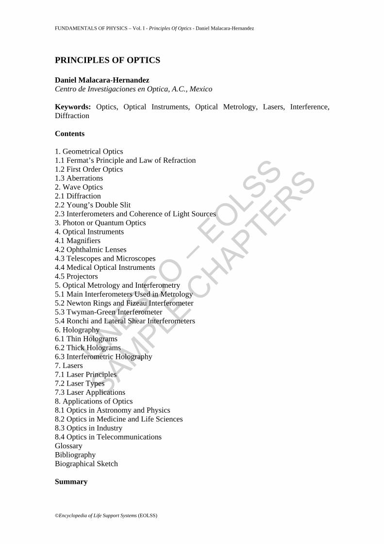
Optics is the study of light and all luminous phenomena. Luminous phenomena can be of many kinds, related to the interaction of light with matter, like reflection, refraction, diffraction and scattering. On the other hand, light, is generally defined as that range of electromagnetic waves to which the eye is sensitive, plus those in the near vicinity. Thus, light also includes the near ultraviolet and the near infrared regions. Wave optics studies the light as an electromagnetic wave, geometrical or ray optics considers light as rays and quantum optics considers light as photons. In this chapter we will briefly describe these three aspects of optics. The applications of optics and optical science are extremely numerous and interesting in many fields. In this chapter we will describe some of the most important. 1. Geometrical Optics Light is an electromagnetic wave propagating in the perpendicular direction to the wavefronts, according to the Malus law. A wavefront is a surface in space with has a constant phase at a given time for all points in the surface. A light ray is a mathematical entity describing the direction in which the light energy propagates. In the next sections we will study geometrical optics. 1.1 Fermat’s Principle and Law of Refraction The basis of all geometrical optics theory is the Fermat principle which states that the path followed by the light when traveling from one point in space to another is that for which the traveling time is an extremum. Thus, the traveling time is a minimum, maximum or stationary with respect to any neighboring path. The speed of light is different in different media, with a maximum value c = 299,792 km/sec in vacuum and smaller in any other medium. The refractive index n is defined as the ratio of the speed of light in vacuum to the speed of light in that medium as follows
cn = v
(1)
This refractive index is in most practical cases greater than one. The refractive indices values for some transparent media are given in the following Table 1.
Material Refractive index Vacuum 1.0000 Air 1.0003 Water 1.33 Fused silica 1.46 Plexiglass 1.49 Borosilicate crown 1.51 Ordinary crown 1.52 Canada Balsam 1.53
UNESCO – EOLS
S
SAMPLE C
HAPTERS
FUNDAMENTALS OF PHYSICS – Vol. I - Principles Of Optics - Daniel Malacara-Hernandez
Light flint 1.57 Extra dense barium crown 1.62 Extra dense flint 1.72 Diamond 2.42
Table 1: Refractive indices for some transparent materials
Figure 1: Fermat’s Principle in a reflecting sphere and a reflecting ellipsoid The optical path OP, from one point P1 to another point P2 is defined as the physical distance multiplied by the refractive index, as follows
2
1
P
P
OP = n dx∫ (2)
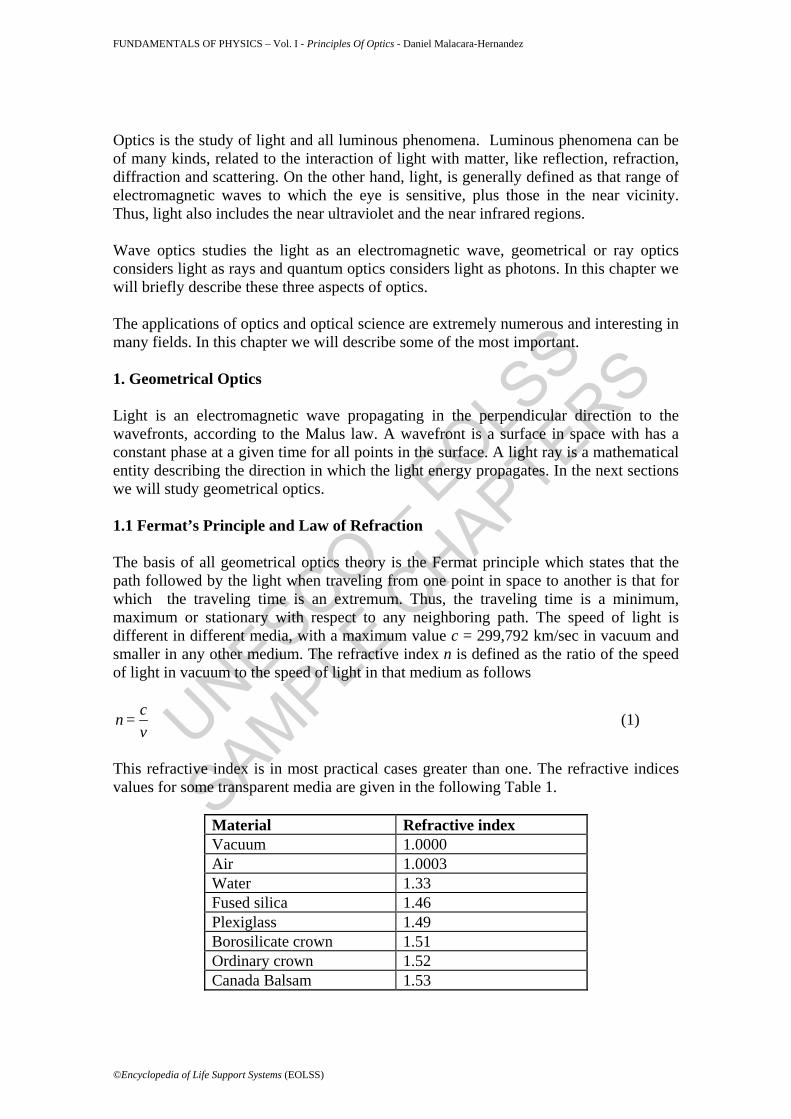
r a reflecting circle and a reflecting ellipse. The laws of refraction and reflection can then be derived from the Fermat’s principle. Thus, if the light travels from one point P1 in a medium with refractive index n to a point P2 in a medium with refractive index n=, separated by a plane interface, as is Fig. 2 we have
sin sinn I = n I′ ′ (3) where I and I= are the angles forming the incident and refracted rays with respect to the normal to the flat interface. Besides, the incident and the refracted rays are in a common plane with the interface normal. This is Snell=s refraction law. BY close analogy, the reflection law is I = - I ′ (4) which is a special case of Snell=s law when n = - n=.
UNESCO – EOLS
S
SAMPLE C
HAPTERS
FUNDAMENTALS OF PHYSICS – Vol. I - Principles Of Optics - Daniel Malacara-Hernandez
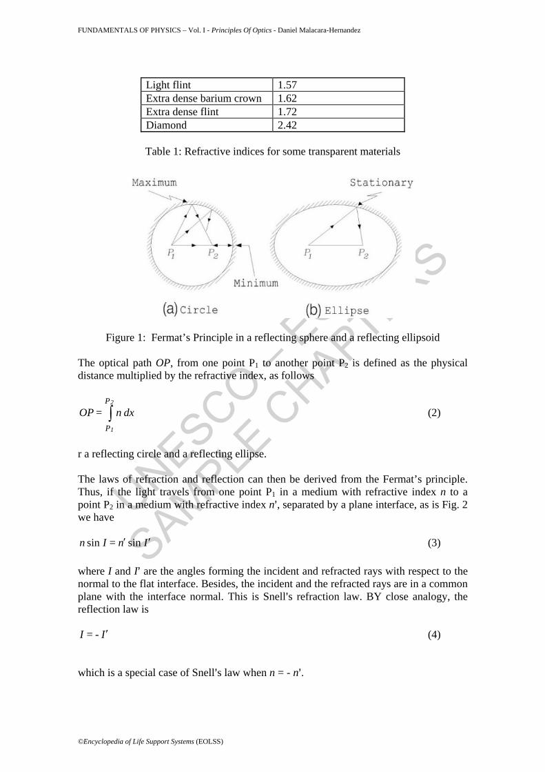
Figure 2: Snell=s Law of reflection 1.2 First Order Optics Most reflective or refractive surfaces used in optical systems are spherical or flat, where a flat surface can be considered as a spherical surface with an infinite radius of curvature. Non spherical surfaces are called aspheric surfaces but their use is quite restricted to special optical systems. So, it is natural to begin with the study of systems with only spherical surfaces. The spherical surface is a circular section of a sphere with radius of curvature r. The center V of the circular section is the vertex. A straight line passing through the vertex V and the center of curvature C is the optical axis. In a system with homogeneous refractive indices a light ray follows a straight trajectory in the first medium. If it is not in a common plane with the optical axis it is an oblique ray, but the geometry involved in the refraction of oblique rays is a little complicated.
Figure 3: Refraction of a ray of light in a spherical surface.
If the ray of light is in a common plane with the optical axis it is also called a meridional ray and the plane containing both rays is the meridional plane. This plane is the drawing plane. Meridional rays provide most of the important properties of optical
UNESCO – EOLS
S
SAMPLE C
HAPTERS
FUNDAMENTALS OF PHYSICS – Vol. I - Principles Of Optics - Daniel Malacara-Hernandez
systems. Let us consider a meridional ray with the parameters indicated in Fig. 3. The incident ray has two degrees of freedom, i.e., the angle slope U with respect to the optical axis and the distance from the vertex to the intersection of the ray with the optical axis L. The refracted ray is also defined by two parameters (U= and L=. Thus, four equations are necessary to define the ray paths sin sin I U = - L - r r
′ ′′
(5)
sin sin I U = - L - r r
′ ′′
(6)
- U + I = - U + I′ ′ (7) and
sin sinn I = n I′ ′ (8) With these four expressions we can show that if a beam of rays starts from a common point on the optical axis (object), they pass very close to each other at another point in the optical axis (object) as illustrated in Fig. 4. We see that if the diameter of the surface is sufficiently reduced, we can consider all rays to be refracted to a common point. These meridional rays, which are not far from the optical axis, are the paraxial rays.
Figure 4: Converging of a beam of rays in a spherical refracting surface The study of paraxial rays is called paraxial or first order optics. Thus, we can replace the sine of the angles by the angles measured in radians. Then, it is possible to obtain the following useful relation known as gaussian equation. n - n n n = -
r l l′ ′
′ (9)
With two spherical surfaces aligned in a common optical axis we have a lens. If the
separation between the surfaces is very small as compared with the radii of curvature of the surfaces we have a thin lens. Applying the gaussian equation to the two surfaces of a thin lens we may obtain:
UNESCO – EOLS
S
SAMPLE C
HAPTERS
FUNDAMENTALS OF PHYSICS – Vol. I - Principles Of Optics - Daniel Malacara-Hernandez
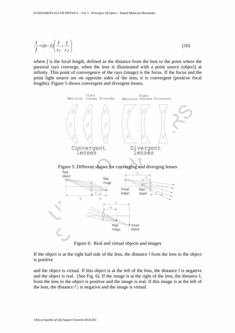
where f is the focal length, defined as the distance from the lens to the point where the paraxial rays converge, when the lens is illuminated with a point source (object) at infinity. This point of convergence of the rays (image) is the focus. If the focus and the point light source are on opposite sides of the lens, it is convergent (positive focal lengths). Figure 5 shows convergent and divergent lenses.
Figure 5: Different shapes for converging and diverging lenses
Figure 6: Real and virtual objects and images If the object is at the right had side of the lens, the distance l from the lens to the object is positive and the object is virtual. If this object is at the left of the lens, the distance l is negative and the object is real. (See Fig. 6). If the image is at the right of the lens, the distance l1 from the lens to the object is positive and the image is real. If this image is at the left of the lens, the distance l’2 is negative and the image is virtual.
UNESCO – EOLS
S
SAMPLE C
HAPTERS
FUNDAMENTALS OF PHYSICS – Vol. I - Principles Of Optics - Daniel Malacara-Hernandez
The object and image distances for a thin lens are related by
2 1
1 1 1 = - f l l′
(11)
Optical systems with spherical surfaces with a common axis of symmetry can also be described with first order optics, as in many geometrical optics textbooks.
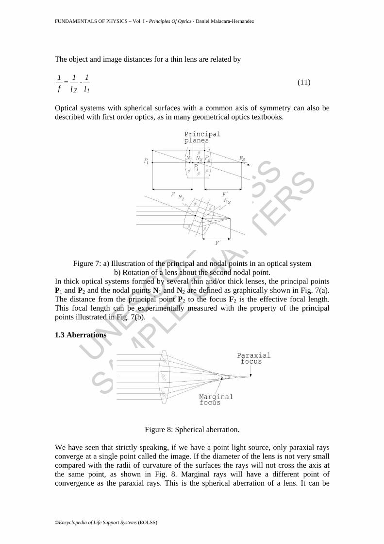
Figure 7: a) Illustration of the principal and nodal points in an optical system b) Rotation of a lens about the second nodal point.
In thick optical systems formed by several thin and/or thick lenses, the principal points P1 and P2 and the nodal points N1 and N2 are defined as graphically shown in Fig. 7(a). The distance from the principal point P2 to the focus F2 is the effective focal length. This focal length can be experimentally measured with the property of the principal points illustrated in Fig. 7(b). 1.3 Aberrations
Figure 8: Spherical aberration. We have seen that strictly speaking, if we have a point light source, only paraxial rays converge at a single point called the image. If the diameter of the lens is not very small compared with the radii of curvature of the surfaces the rays will not cross the axis at the same point, as shown in Fig. 8. Marginal rays will have a different point of convergence as the paraxial rays. This is the spherical aberration of a lens. It can be
UNESCO – EOLS
S
SAMPLE C
HAPTERS
FUNDAMENTALS OF PHYSICS – Vol. I - Principles Of Optics - Daniel Malacara-Hernandez
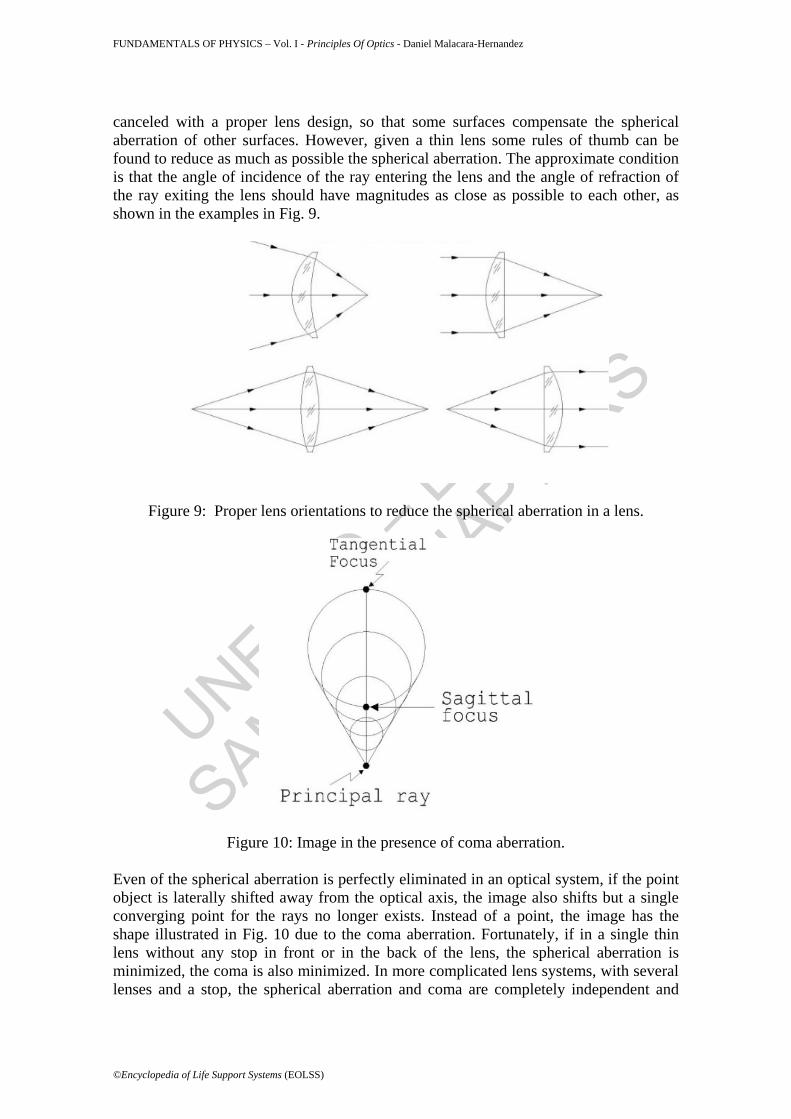
canceled with a proper lens design, so that some surfaces compensate the spherical aberration of other surfaces. However, given a thin lens some rules of thumb can be found to reduce as much as possible the spherical aberration. The approximate condition is that the angle of incidence of the ray entering the lens and the angle of refraction of the ray exiting the lens should have magnitudes as close as possible to each other, as shown in the examples in Fig. 9.
Figure 9: Proper lens orientations to reduce the spherical aberration in a lens.
Figure 10: Image in the presence of coma aberration.
Even of the spherical aberration is perfectly eliminated in an optical system, if the point object is laterally shifted away from the optical axis, the image also shifts but a single converging point for the rays no longer exists. Instead of a point, the image has the shape illustrated in Fig. 10 due to the coma aberration. Fortunately, if in a single thin lens without any stop in front or in the back of the lens, the spherical aberration is minimized, the coma is also minimized. In more complicated lens systems, with several lenses and a stop, the spherical aberration and coma are completely independent and
UNESCO – EOLS
S
SAMPLE C
HAPTERS
FUNDAMENTALS OF PHYSICS – Vol. I - Principles Of Optics - Daniel Malacara-Hernandez
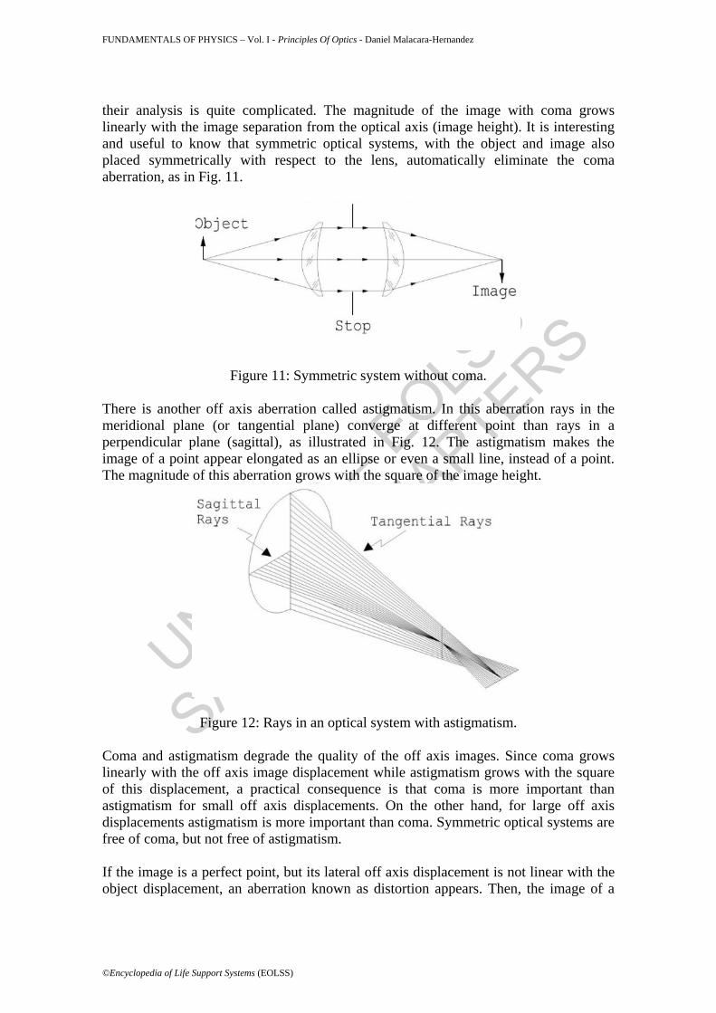
their analysis is quite complicated. The magnitude of the image with coma grows linearly with the image separation from the optical axis (image height). It is interesting and useful to know that symmetric optical systems, with the object and image also placed symmetrically with respect to the lens, automatically eliminate the coma aberration, as in Fig. 11.
Figure 11: Symmetric system without coma.
There is another off axis aberration called astigmatism. In this aberration rays in the meridional plane (or tangential plane) converge at different point than rays in a perpendicular plane (sagittal), as illustrated in Fig. 12. The astigmatism makes the image of a point appear elongated as an ellipse or even a small line, instead of a point. The magnitude of this aberration grows with the square of the image height.
Figure 12: Rays in an optical system with astigmatism. Coma and astigmatism degrade the quality of the off axis images. Since coma grows linearly with the off axis image displacement while astigmatism grows with the square of this displacement, a practical consequence is that coma is more important than astigmatism for small off axis displacements. On the other hand, for large off axis displacements astigmatism is more important than coma. Symmetric optical systems are free of coma, but not free of astigmatism. If the image is a perfect point, but its lateral off axis displacement is not linear with the object displacement, an aberration known as distortion appears. Then, the image of a
UNESCO – EOLS
S
SAMPLE C
HAPTERS
FUNDAMENTALS OF PHYSICS – Vol. I - Principles Of Optics - Daniel Malacara-Hernandez
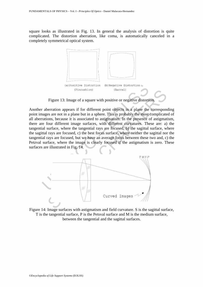
square looks as illustrated in Fig. 13. In general the analysis of distortion is quite complicated. The distortion aberration, like coma, is automatically canceled in a completely symmetrical optical system.
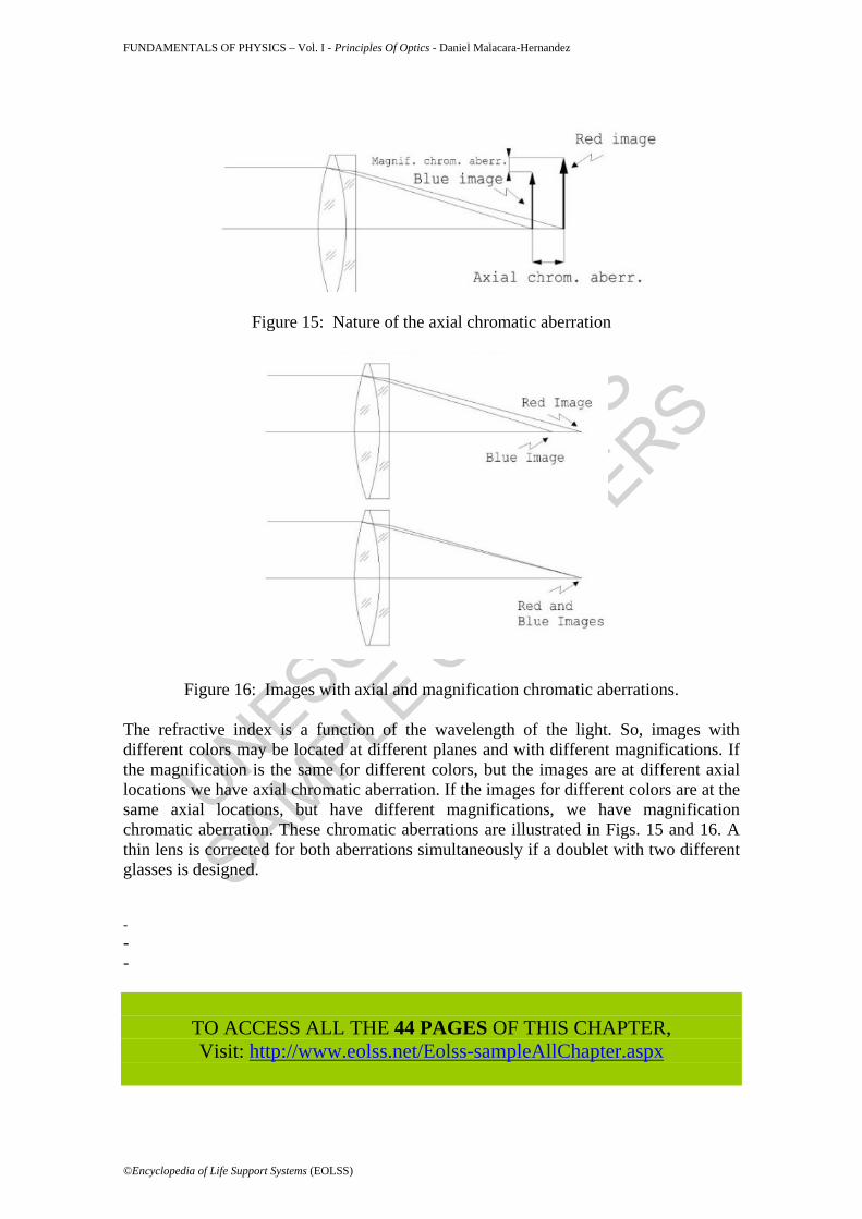
Figure 13: Image of a square with positive or negative distortion. Another aberration appears if for different point objects in a plane the corresponding point images are not in a plane but in a sphere. This is probably the most complicated of all aberrations, because it is associated to astigmatism. In the presence of astigmatism, there are four different image surfaces, with different curvatures. These are: a) the tangential surface, where the tangential rays are focused, b) the sagittal surface, where the sagittal rays are focused, c) the best focus surface, where neither the sagittal nor the tangential rays are focused, but we have an average focus between these two and, c) the Petzval surface, where the image is clearly focused if the astigmatism is zero. These surfaces are illustrated in Fig. 14.
Figure 14: Image surfaces with astigmatism and field curvature. S is the sagittal surface, T is the tangential surface, P is the Petsval surface and M is the medium surface,
between the tangential and the sagittal surfaces.
UNESCO – EOLS
S
SAMPLE C
HAPTERS
FUNDAMENTALS OF PHYSICS – Vol. I - Principles Of Optics - Daniel Malacara-Hernandez
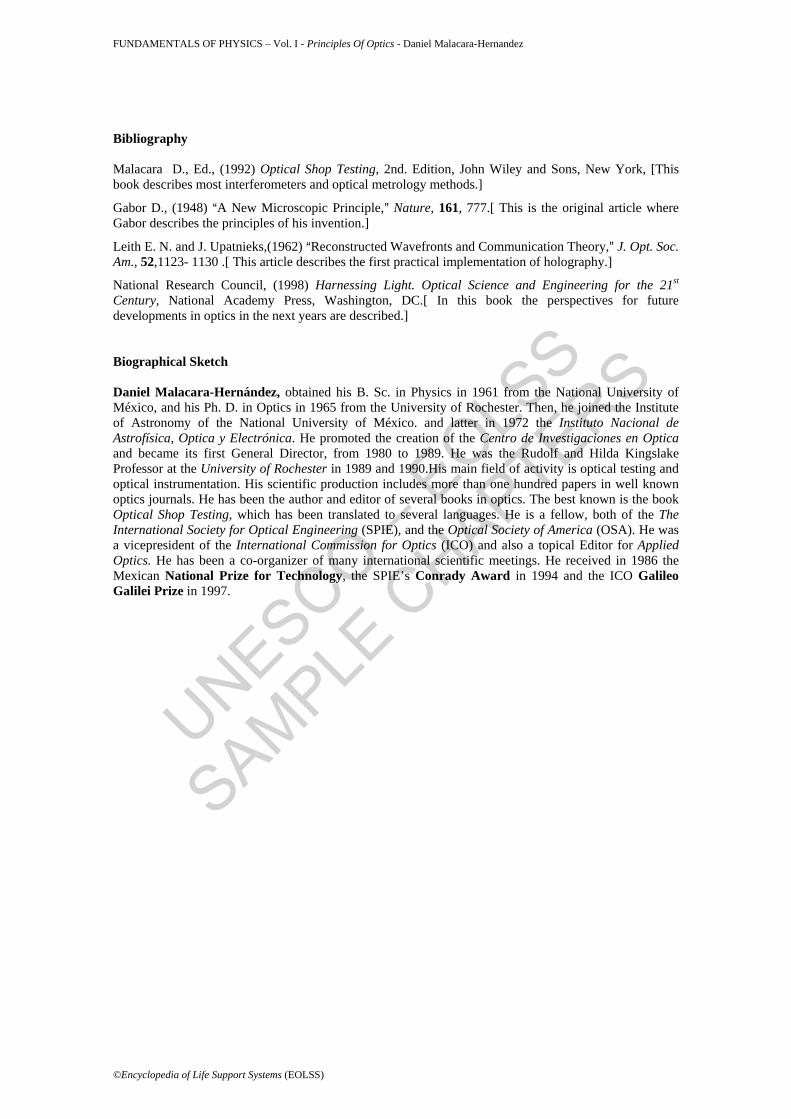
Figure 15: Nature of the axial chromatic aberration
Figure 16: Images with axial and magnification chromatic aberrations. The refractive index is a function of the wavelength of the light. So, images with different colors may be located at different planes and with different magnifications. If the magnification is the same for different colors, but the images are at different axial locations we have axial chromatic aberration. If the images for different colors are at the same axial locations, but have different magnifications, we have magnification chromatic aberration. These chromatic aberrations are illustrated in Figs. 15 and 16. A thin lens is corrected for both aberrations simultaneously if a doublet with two different glasses is designed. - - -
TO ACCESS ALL THE 44 PAGES OF THIS CHAPTER, Visit: http://www.eolss.net/Eolss-sampleAllChapter.aspx
Bibliography Malacara D., Ed., (1992) Optical Shop Testing, 2nd. Edition, John Wiley and Sons, New York, [This book describes most interferometers and optical metrology methods.]
Gabor D., (1948) AA New Microscopic Principle,@ Nature, 161, 777.[ This is the original article where Gabor describes the principles of his invention.]
Leith E. N. and J. Upatnieks,(1962) AReconstructed Wavefronts and Communication Theory,@ J. Opt. Soc. Am., 52,1123- 1130 .[ This article describes the first practical implementation of holography.]
National Research Council, (1998) Harnessing Light. Optical Science and Engineering for the 21st Century, National Academy Press, Washington, DC.[ In this book the perspectives for future developments in optics in the next years are described.] Biographical Sketch Daniel Malacara-Hernández, obtained his B. Sc. in Physics in 1961 from the National University of México, and his Ph. D. in Optics in 1965 from the University of Rochester. Then, he joined the Institute of Astronomy of the National University of México. and latter in 1972 the Instituto Nacional de Astrofísica, Optica y Electrónica. He promoted the creation of the Centro de Investigaciones en Optica and became its first General Director, from 1980 to 1989. He was the Rudolf and Hilda Kingslake Professor at the University of Rochester in 1989 and 1990.His main field of activity is optical testing and optical instrumentation. His scientific production includes more than one hundred papers in well known optics journals. He has been the author and editor of several books in optics. The best known is the book Optical Shop Testing, which has been translated to several languages. He is a fellow, both of the The International Society for Optical Engineering (SPIE), and the Optical Society of America (OSA). He was a vicepresident of the International Commission for Optics (ICO) and also a topical Editor for Applied Optics. He has been a co-organizer of many international scientific meetings. He received in 1986 the Mexican National Prize for Technology, the SPIE’s Conrady Award in 1994 and the ICO Galileo Galilei Prize in 1997.