86
Technical Guide X-TYPE Estate Introduction Plus X-TYPE, S-TYPE, XK 2005 Model Year Updates
Technical Guide
X-TYPE EstateIntroduction
Plus X-TYPE, S-TYPE, XK2005 Model Year
Updates


.
Technical Guide
X-TYPE EstateIntroduction
Plus X-TYPE, S-TYPE, XK2005 Model Year
Updates
Published by Technical Communications, Jaguar Cars LimitedPublication Part No. JJM 18 15 99/50, January 2004

Preface
The Jaguar Technical Guide is intended to provide an overview only and must not be used as a reference source for servicingprocedures. All servicing must be carried out in accordance with ‘JTIS / GTR’.
While every effort is made to ensure accuracy, design changes to the vehicle may be made in the period between the completionof this publication and the introduction of vehicles. Details of changes can be obtained from Service Bulletins and revisions on‘JTIS / GTR’.
All rights reserved. No part of this publication may be reproduced, stored in a retrieval system or transmitted, in any form:electronic, mechanical, including photocopying, recording or other means without prior written permission from the ServiceDivision of Jaguar Cars Limited.
IV

Contents
Subject .. . . . . . . . . . . . . . . . . . . . . . . . . . . . . . . . . . . . . . . . . . . . . . . . . . . . . . . . Page
GlossaryAbbreviations and Acronyms . . . . . . . . . . . . . . . . . . . . . . . . . . . . . . . . . . . . . . . . VIII
Introduction . . . . . . . . . . . . . . . . . . . . . . . . . . . . . . . . . . . . . . . . . . . . . . . . . . . . . . . . . . . . . . . . . . . 1Publication Layout . . . . . . . . . . . . . . . . . . . . . . . . . . . . . . . . . . . . . . . . . . . . . . . . . . . . . . 1
X-TYPE Estate Introduction and Sedan Model Year Update . . . . . . 1S-TYPE Model Year Update. . . . . . . . . . . . . . . . . . . . . . . . . . . . . . . . . . . . . . . . . 1XK Model Year Update . . . . . . . . . . . . . . . . . . . . . . . . . . . . . . . . . . . . . . . . . . . . . 2
General InformationDimensions (X-TYPE Estate) . . . . . . . . . . . . . . . . . . . . . . . . . . . . . . . . . . . . . . . . . . . . 3
Chassis (X-TYPE)Brake System. . . . . . . . . . . . . . . . . . . . . . . . . . . . . . . . . . . . . . . . . . . . . . . . . . . . . . . . . . . . 4
Rear Caliper (Estate and Sedan) . . . . . . . . . . . . . . . . . . . . . . . . . . . . . . . . . . . . 4Steering System . . . . . . . . . . . . . . . . . . . . . . . . . . . . . . . . . . . . . . . . . . . . . . . . . . . . . . . . . 5
Steering Wheel (Estate and Sedan). . . . . . . . . . . . . . . . . . . . . . . . . . . . . . . . . 5Steering Wheel Switches (Estate and Sedan) . . . . . . . . . . . . . . . . . . . . . . 5
Powertrain (X-TYPE)Fuel Charging and Controls . . . . . . . . . . . . . . . . . . . . . . . . . . . . . . . . . . . . . . . . . . . . 7
Organ Throttle Pedal (Estate and Sedan) . . . . . . . . . . . . . . . . . . . . . . . . . . 7
Electrical (X-TYPE)In-vehicle Entertainment Systems. . . . . . . . . . . . . . . . . . . . . . . . . . . . . . . . . . . . . . 8
Audio System (Estate and Sedan) . . . . . . . . . . . . . . . . . . . . . . . . . . . . . . . . . . 8Electrical Distribution . . . . . . . . . . . . . . . . . . . . . . . . . . . . . . . . . . . . . . . . . . . . . . . . . 11
Multimedia Modules (Estate) . . . . . . . . . . . . . . . . . . . . . . . . . . . . . . . . . . . . . . 11Electronic Feature Group. . . . . . . . . . . . . . . . . . . . . . . . . . . . . . . . . . . . . . . . . . . . . . 12
Anti-Theft (Estate). . . . . . . . . . . . . . . . . . . . . . . . . . . . . . . . . . . . . . . . . . . . . . . . . . 12Telematics (Estate and Sedan) . . . . . . . . . . . . . . . . . . . . . . . . . . . . . . . . . . . . . 14Multifunction Electronic Control Modules (Estate). . . . . . . . . . . . . . . 15
Body (X-TYPE)Body System Exterior . . . . . . . . . . . . . . . . . . . . . . . . . . . . . . . . . . . . . . . . . . . . . . . . . . 16
General (Estate) . . . . . . . . . . . . . . . . . . . . . . . . . . . . . . . . . . . . . . . . . . . . . . . . . . . . 16Filler Flap, Hinge and Bowl (Estate) . . . . . . . . . . . . . . . . . . . . . . . . . . . . . . . 17Body Closures and Tailgate (Estate) . . . . . . . . . . . . . . . . . . . . . . . . . . . . . . . 18Glass and Frames (Estate) . . . . . . . . . . . . . . . . . . . . . . . . . . . . . . . . . . . . . . . . . 20Rear Wiper System (Estate) . . . . . . . . . . . . . . . . . . . . . . . . . . . . . . . . . . . . . . . . 20Exterior Trim Components (Estate) . . . . . . . . . . . . . . . . . . . . . . . . . . . . . . . 23Rear Bumper and Beam (Estate). . . . . . . . . . . . . . . . . . . . . . . . . . . . . . . . . . . 25
Body System Interior . . . . . . . . . . . . . . . . . . . . . . . . . . . . . . . . . . . . . . . . . . . . . . . . . . 26Luggage Compartment Trim (Estate) . . . . . . . . . . . . . . . . . . . . . . . . . . . . . . 26Tailgate Trim (Estate). . . . . . . . . . . . . . . . . . . . . . . . . . . . . . . . . . . . . . . . . . . . . . . 28Luggage Cover and Load Net (Estate) . . . . . . . . . . . . . . . . . . . . . . . . . . . . . 29
Seating. . . . . . . . . . . . . . . . . . . . . . . . . . . . . . . . . . . . . . . . . . . . . . . . . . . . . . . . . . . . . . . . . . 32Front Seats (Estate and Sedan) . . . . . . . . . . . . . . . . . . . . . . . . . . . . . . . . . . . . 32Rear Seats (Estate) . . . . . . . . . . . . . . . . . . . . . . . . . . . . . . . . . . . . . . . . . . . . . . . . . 33
V

Contents
Occupant Safety (X-TYPE)Advanced Restraints System. . . . . . . . . . . . . . . . . . . . . . . . . . . . . . . . . . . . . . . . . . . 34
Restraints Control Module (Estate and Sedan) . . . . . . . . . . . . . . . . . . . 34Sensors (Estate and Sedan) . . . . . . . . . . . . . . . . . . . . . . . . . . . . . . . . . . . . . . . . 35Rear Safety Belts (Estate). . . . . . . . . . . . . . . . . . . . . . . . . . . . . . . . . . . . . . . . . . . 39Driver Air Bag Module (Estate and Sedan). . . . . . . . . . . . . . . . . . . . . . . . 40Passenger Air Bag Deployment Door — NAS only (Estate andSedan) . . . . . . . . . . . . . . . . . . . . . . . . . . . . . . . . . . . . . . . . . . . . . . . . . . . . . . . . . . . . . . 41Side Curtain Air Bag (Estate). . . . . . . . . . . . . . . . . . . . . . . . . . . . . . . . . . . . . . . 42Driver Lower Air Bag Module (Estate and Sedan) . . . . . . . . . . . . . . . . 43
Chassis (S-TYPE)Brake System. . . . . . . . . . . . . . . . . . . . . . . . . . . . . . . . . . . . . . . . . . . . . . . . . . . . . . . . . . . 44
Electric Park Brake . . . . . . . . . . . . . . . . . . . . . . . . . . . . . . . . . . . . . . . . . . . . . . . . . 44Steering System . . . . . . . . . . . . . . . . . . . . . . . . . . . . . . . . . . . . . . . . . . . . . . . . . . . . . . . . 46
Power Assisted Steering System. . . . . . . . . . . . . . . . . . . . . . . . . . . . . . . . . . . 46
Powertrain (S-TYPE)Evaporative Emissions . . . . . . . . . . . . . . . . . . . . . . . . . . . . . . . . . . . . . . . . . . . . . . . . . 47
Features of the NAS Carbon Can. . . . . . . . . . . . . . . . . . . . . . . . . . . . . . . . . . 47Features of the ROW Carbon Can . . . . . . . . . . . . . . . . . . . . . . . . . . . . . . . . 47
Fuel Tank and Lines . . . . . . . . . . . . . . . . . . . . . . . . . . . . . . . . . . . . . . . . . . . . . . . . . . . . 48Features of the Fuel Tank . . . . . . . . . . . . . . . . . . . . . . . . . . . . . . . . . . . . . . . . . . 48
Vehicle Speed Control . . . . . . . . . . . . . . . . . . . . . . . . . . . . . . . . . . . . . . . . . . . . . . . . . 51Adaptive Cruise Control . . . . . . . . . . . . . . . . . . . . . . . . . . . . . . . . . . . . . . . . . . . 51
Electrical (S-TYPE)Instrumentation and Warning Systems . . . . . . . . . . . . . . . . . . . . . . . . . . . . . . . 53
Instrument Cluster . . . . . . . . . . . . . . . . . . . . . . . . . . . . . . . . . . . . . . . . . . . . . . . . . 53Parking Aid . . . . . . . . . . . . . . . . . . . . . . . . . . . . . . . . . . . . . . . . . . . . . . . . . . . . . . . . . . . . . 54Lighting. . . . . . . . . . . . . . . . . . . . . . . . . . . . . . . . . . . . . . . . . . . . . . . . . . . . . . . . . . . . . . . . . 55
Exterior Lighting . . . . . . . . . . . . . . . . . . . . . . . . . . . . . . . . . . . . . . . . . . . . . . . . . . . 55Battery and Charging Systems.. . . . . . . . . . . . . . . . . . . . . . . . . . . . . . . . . . . . . . . . 56
Battery Cable. . . . . . . . . . . . . . . . . . . . . . . . . . . . . . . . . . . . . . . . . . . . . . . . . . . . . . . 56Electronic Feature Group.. . . . . . . . . . . . . . . . . . . . . . . . . . . . . . . . . . . . . . . . . . . . . 58
V60 Telephone - NAS.. . . . . . . . . . . . . . . . . . . . . . . . . . . . . . . . . . . . . . . . . . . . . 58
Body (S-TYPE)Body System Exterior . . . . . . . . . . . . . . . . . . . . . . . . . . . . . . . . . . . . . . . . . . . . . . . . . . 59
Hood and Mounting . . . . . . . . . . . . . . . . . . . . . . . . . . . . . . . . . . . . . . . . . . . . . . . 60Luggage Compartment Lid and Hinges . . . . . . . . . . . . . . . . . . . . . . . . . . . 60Hood and Luggage Compartment Lid Seals . . . . . . . . . . . . . . . . . . . . . . 60Underbody Systems . . . . . . . . . . . . . . . . . . . . . . . . . . . . . . . . . . . . . . . . . . . . . . . 61Front and Rear Bumper Systems . . . . . . . . . . . . . . . . . . . . . . . . . . . . . . . . . . 62Exterior Trim .. . . . . . . . . . . . . . . . . . . . . . . . . . . . . . . . . . . . . . . . . . . . . . . . . . . . . . 63Windscreen Wiper System . . . . . . . . . . . . . . . . . . . . . . . . . . . . . . . . . . . . . . . . 65
Powertrain (XK)Exhaust System . . . . . . . . . . . . . . . . . . . . . . . . . . . . . . . . . . . . . . . . . . . . . . . . . . . . . . . . 66
Exhaust Tailpipes. . . . . . . . . . . . . . . . . . . . . . . . . . . . . . . . . . . . . . . . . . . . . . . . . . . 66Vehicle Speed Control . . . . . . . . . . . . . . . . . . . . . . . . . . . . . . . . . . . . . . . . . . . . . . . . . 68
Adaptive Cruise Control . . . . . . . . . . . . . . . . . . . . . . . . . . . . . . . . . . . . . . . . . . . 68
VI

Contents
Body (XK)Body System Exterior . . . . . . . . . . . . . . . . . . . . . . . . . . . . . . . . . . . . . . . . . . . . . . . . . . 70
Bumpers. . . . . . . . . . . . . . . . . . . . . . . . . . . . . . . . . . . . . . . . . . . . . . . . . . . . . . . . . . . . 70Sill Appliqué . . . . . . . . . . . . . . . . . . . . . . . . . . . . . . . . . . . . . . . . . . . . . . . . . . . . . . . 72Rear Spoilers . . . . . . . . . . . . . . . . . . . . . . . . . . . . . . . . . . . . . . . . . . . . . . . . . . . . . . . 73Exterior Trim Finishers . . . . . . . . . . . . . . . . . . . . . . . . . . . . . . . . . . . . . . . . . . . . 73
VII

Glossary
The following abbreviations and acronyms are used in this publication:
Abbreviation / Acronym Description
ac alternating currentACC adaptive cruise controlACCM adaptive cruise control moduleAM amplitude modulationAMS automatic music searchASL automatic speed limiterBIW body-in-whiteBTS belt tension sensorCD compact discCHMSL centre high mounted stop lampcm centimeterD2B digital data busdc direct currentDTC diagnostic trouble codeDVD digital versatile discFM frequency modulationGECM General Electronic Control ModuleGPS global positioning systemGTR Global Technical ReferenceGVW gross vehicle weightin inchISO International Standards OrganizationJTIS Jaguar Technical Information Systemkbps kilobits per secondkm/h kilometers per hourkV kilovoltLED light emitting diodeLH left-handLHD left-hand driveMHz megahertzMIL malfunction indicator lampmile/h miles per hourmm millimeterms millisecondMY model yearN newtonNAS North American specificationOBD on-board diagnosticsPCM powertrain control moduleRCM restraints control moduleRF radio frequencyRH right-handRHD right-hand driveRKE remote keyless entryROW Rest of WorldSRS supplementary restraints systemTG technical guide
VIII

Glossary
VEMS vehicle emergency messaging systemVICS vehicle information communications systemVIN vehicle identification numberW wattWDS worldwide diagnostic system
IX


Introduction
Publication LayoutThis publication is split into three sections one for each vehicle model; refer to the contents pages and page heading for therequired model.
X-TYPE Estate Introduction and Sedan Model Year UpdateThe introduction of Jaguar’s first estate model coincides with the sedan model year update. The estate is a new body style basedon the X-TYPE sedan. Key points are:
• Unique body shell from the ‘B’ pillar rearwards.
• Standard fitment roof bars.
• Unique tailgate with independent opening backlight.
• Rear wash/wipe system.
• Unique exterior trim, including rear roof spoiler with center high-mounted stop lamp and washer nozzle.
• Unique interior trim with new rear seats, luggage cover with load net and underfloor storage compartment.
Model year updates for the sedan include the following but note that some features are vehicle or market specific:
• Memory feature for the driver’s seat and rear view door mirrors.
• Driver’s lower air bag.
• New steering wheel with entertainment and speed control switchpacks and driver air bag module.
• Revised restraints control module.
• Floor mounted organ throttle pedal.
S-TYPE Model Year UpdateThe update of this model incorporates changes to the following systems:
• Power assisted steering.
• Electronic park brake.
• Fuel system.
• Instrument cluster.
• Starter motor cable route.
• Telephone (NAS).
• Adaptive cruise control.
• Parking aid.
• Body panels and engine undertray.
• Exterior lighting.
• Exterior trim.
• Windscreen wipers and washer.
These changes are to update the vehicle’s appearance, to incorporate both, technical advancements and feedback from Jaguardealers and owners.
1

Introduction
XK Model Year UpdateMinor freshening actions are applied to the XK8 range to enhance the external appearance and introduce cruise (speed) controlmodifications. Note that some features are vehicle or market specific.
Changes to the Body area include:
• New front and rear bumper covers.
• New sill appliqué.
• New rear spoiler for XKR and fitment of former XKR spoiler to XK8.
• New exhaust tailpipe finishers for XKR and fitment of former XKR finishers to XK8.
Changes to the cruise (speed) control include:
• Update of adaptive cruise control from version ACC-2 to version ACC-3.
• Introduction of automatic speed limiter feature.
2

General Information
Dimensions (X-TYPE Estate)
Fig. 1 External dimensions
Dimension inches millimeters
A 185.7 4716
B 106.7 2710
C 59.9 1522
D 60.5 1537
E 78.8 2003
F 70.4 1789
G 55.5 (57.2) 1409 (1451)
Table 1 External dimensions (refer to Fig. 1)
Measurement ‘G’ is at design weight condition, which refers toa vehicle kerb weight including 33% optional equipment, plusoccupant load. Dimension to the roof bars shown in brackets.
NOTE: Measurement ‘G’ for kerb weight condition (completevehicle with all fluids filled to capacity without occupants,optional equipment or luggage) = 56.7 in (1441 mm). To theroof bars = 58.4 in (1483 mm).
Minimum ground clearance (fuel tank undertray to ground)measured at gross vehicle weight (GVW)=4.4 in (112.90mm).
3

Chassis (X-TYPE)
Brake System
Rear Caliper (Estate and Sedan)A new ’Ball-in-Ramp 3’ rear caliper will be introduced as arunning change to reduce weight, improve cabin lever loadsand reduce rear brake noise.
Fig. 2 Rear caliper
4

Chassis (X-TYPE)
Steering System
Steering Wheel (Estate and Sedan)The steering wheel is a hybrid armature comprising:
• Magnesium hub and upper spokes;
• Steel rim and lower spokes.
The steering wheel is available in many different styles to suitthe model and chosen features.
The driver’s air bag is a new design to suit the steering wheeland is removed using a different method to previous air bags;refer to ‘JTIS / GTR’.
Fig. 3 Steering wheel
Steering Wheel Switches (Estate andSedan)The wheel has all-new steering wheel mounted switches,serviceable in the normal manner.
Entertainment Switchpack
The switchpack comprises:
• Two buttons for mode selection and mute/phone;
• Two rotary thumb wheels (which have a 30 angle ofrotation) for the volume and seek functions.
Fig. 4 Entertainment switchpack
5

Chassis (X-TYPE)
Speed Control Switchpack
The switchpack comprises:
• Two buttons for resume and cancel features;
• A rotary thumb wheel used for speed increase anddecrease.
Fig. 5 Speed control switchpack
Rear Wash/Wipe Column Switch (Estate)
Estate models are fitted with a rear screen wash/wipe, whichis operated by the right-hand column stalk and only operateswith the ignition in position ‘II’. If the windscreen wipers areswitched on and reverse gear is selected, the rear wiper willwipe intermittently. If the rear wiper is set to intermittentwhen reverse gear is selected, the rear wiper will wipecontinuously.
Fig. 6 Wash/wipe column switch
1. Rear wiper off and parked
2. Intermittent wipe
3. Continuous wash and wipe
6

Powertrain (X-TYPE)
Fuel Charging and Controls
Organ Throttle Pedal (Estate and Sedan)The organ throttle pedal supplements the driver lower air bagmodule. It helps control the driver’s heel point and offers amore refined pedal feel over the former pendulum pedal. Theorgan throttle pedal comprises:
• throttle sensor mounting bracket with pedal stop;
• throttle sensor;
• organ pad;
• organ pedal mounting bracket.
The throttle sensor’s control arm engages with the organ padand slides freely over its rear bearing when the organ padarticulates from its ’live’ hinge.
Fig. 7 - Organ throttle pedal
1. Throttle sensor mounting bracket with pedal stop
2. Throttle sensors
3. Sensor control arm
4. Organ pad
5. Organ pedal mounting bracket
6. Live hinge
7

Electrical (X-TYPE)
In-vehicle Entertainment Systems
Audio System (Estate and Sedan)Minor refinements are made to the In-vehicle entertainmentsystem including:
• Subwoofer adjustment on premium audio sound systemvehicles.
• Digital signal processing capability on premium audiosound system vehicles. This facilitates adjustment foroptimization of sound for specific seating positions, usingslight time delays between speaker image zones.
• New equalization in the amplifier for premium audio soundsystem vehicles.
• Auto-loudness (to compensate for vehicle speed noise)enhancements with the latest head unit software.
• New steering wheel telematics controls.
On premium audio sound system vehicles, a branded audiosystem is introduced. A remote D2B digital amplifier (320W) isused which replaces the former audio unit integral amplifier.It is located in the luggage compartment, above the stackbracket.
Speakers
The standard audio system is revised from four full rangedoor speakers to a six-speaker arrangement. Each front doorcontains a mid/bass driver and a tweeter. Each rear doorcontains a full range door speaker. The number of speakersfor the premium audio sound system remains at nine: four(upgraded to 2 ohm) mid-bass door speakers, four doormounted tweeters and a new subwoofer speaker. For theestate, the new subwoofer speaker is located in an enclosureon the luggage compartment right-hand side.
Fig. 8 Estate Premium Audio Sound sub-woofer enclosure
8

Electrical (X-TYPE)
Antennas (Estate)
The global positioning system (GPS) antenna is located underthe rear spoiler and is magnetically mounted. The vehicleinformation communications system (VICS) (Japanese market)antenna module is located on the RH side ‘E’ pillar upper areawith the print on the sixth light. The AM/FM and phone rodantenna is fitted on the center line at the rear of the roof.
The TV antenna screen print are located on the LH and RHsixth light. Two modules are located above the LH sixth lightand another two are located above the RH sixth light. Thefixings are one bolt per amplifier.
9

Electrical (X-TYPE)
Fig. 9 Antennas location — estate
1. TV antenna amplifier
2. Phone and AM/FM antenna
3. VICS beacon sensor
4. TV antenna amplifier
5. TV antenna amplifier
6. GPS antenna
7. TV antenna amplifier
8. VICS antenna
10

Electrical (X-TYPE)
Electrical Distribution
Multimedia Modules (Estate)
Stack-Brackets and Components
The estate stack-bracket is similar to the sedan butmodifications are made to accommodate the packagingrequirements of the estate.
Fig. 10 - Stack-bracket
Located on the left-hand side of the luggage compartment, thestack-bracket, houses the following:
• Voice module
• Navigation ECU
• VICS module (Japan only)
• Phone module
• CD autochanger
The inclination sensor is mounted on two weld studs locatedto the left of the stack-bracket. The Premium audio soundsystem amplifier is mounted to a unique bracket above thestack-bracket. It is capable of delivering 8 x 40W output andis part of the D2B network.
Fig. 11 Stack bracket and module location
1. Voice module
2. Navigation ECU
3. VICS module (Japan only)
4. Phone module
5. CD autochanger
6. Premium audio sound system amplifier
7. Inclination sensor
11

Electrical (X-TYPE)
Electronic Feature Group
Anti-Theft (Estate)
Fig. 12 - Anti-theft component locations
12

Electrical (X-TYPE)
Key to Fig. 12
1. Instrument cluster
2. Remote keyless entry RF transmitter
3. Intrusion sensors (modified)
4. Stand alone remote keyless entry RF receiver - new
5. Tailgate latch/ajar switch (new)
6. Opening backlight latch/ajar switch (new)
7. Opening backlight handle with release button (new)
8. Inclination sensor (modified)
9. Door ajar switch
10. Transceiver coil
11. Security system indicator LED (modified)
12. Battery-backed sounder (modified)
13. Horns (modified)
14. Hood ajar switch
15. GECM (modified) - adjacent to ECU
16. Audio unit (non-telematics version)
The estate security system is carry-over sedan with thefollowing changes:
• The perimeter alarm system replaces the trunk latch ajarswitch with individual tailgate door and opening backlightlatch ajar switches. They are under the control of theGeneral Electronic Control Module (GECM).
• The intrusion sensor is modified to provide coverage to therear luggage area of the estate. One part now covers bothsedan and estate with two settings.
• The battery-backed sounder is modified for the estate andsedan.
• The inclination sensor is attached with a bracket to allow acommon estate/sedan solution.
13

Electrical (X-TYPE)
Telematics (Estate and Sedan)
Steering Wheel Telematics Controls
To ensure minimum disruption to concentration when driving,limited control of audio, telephone and voice activationsystems is possible using the steering wheel telematicscontrols.
The controls provide the following functionality:
• Answer phone call, mute, or select voice activation.
• Increase or decrease volume.
• Selection of radio FM, AM, tape cassette, CD, and phoneready mode.
• Cycle through preset radio stations, the next CD track ortape, automatic music search (AMS).
Fig. 13 Steering wheel telematics controls
14

Electrical (X-TYPE)
Multifunction Electronic Control Modules(Estate)
GECM and Remote Keyless Entry Receiver
The general electronic control module (GECM) for the estate isa revised sedan version. It is located in the same place as thesedan, on the right-hand side of the passenger compartment,beneath the instrument panel, close to the ‘A’ pillar.
The additional features on the estate that the GECM controlsare:
• Rear wash/wipe system
• Twin tailgate system and security
Because of the control functions for the above extra features,there is no room left for the remote keyless entry (RKE )previous receiver. Therefore, the receiver is made externalto GECM. The receiver is located under the front end of theheadlining. There are two derivatives: 433.92Mhz withouthelix antenna; 315Mhz with helix antenna. Refer to Fig. 12‘Anti-theft component locations’.
Rear wash/wipe system functions are:
• Intermittent wiper function
• Intermittent wiper function with reverse gear
• Continuous wiper function with reverse gear
• Rear wash function
• Wiper interruption function
• Wiper park control
Twin tailgate system and security functions are:
• External button tailgate door
• External button tailgate opening backlight
• RF function of either tailgate door or opening backlight
• External button function after RF operation
• Courtesy lamp activation from tailgate door or openingbacklight
• Security ajar switches on both tailgate door and openingbacklight.
15

Body (X-TYPE)
Body System Exterior
General (Estate)The X-TYPE estate, when compared to the sedan, has aunique body from the ‘B’ pillar rearwards, with additionalrear quarter windows and tailgate. They are derivatizedbetween all-wheel drive and two-wheel drive versions. Theroof is unique and has two versions: with or without a slidingsunroof. Roof bars are standard fitment. There is a new roofditch moulding, black on all vehicles. The rear floor assembly
is modified to accommodate the open luggage compartmentdesign of an estate. It is therefore without the panel for therear seat squab support, rear parcel shelf and rear parcel shelfside structure. Rear floor additions include wheel housingquarter strengtheners (turrets), plus two torsional stiffnessmembers and two trim brackets to achieve torsional stiffnessrequirements.
Fig. 14 Estate body-in-white (BIW)
16

Body (X-TYPE)
Filler Flap, Hinge and Bowl (Estate)The fuel filler flap and hinge is unique to support the bodyside surface design of the estate. The bowl is a carry-oversedan design, except for the addition of two pins. Althoughthe release system (cables, handles and clips) are carry overitems, the cable routing is changed slightly, near the filler flap,due to the difference between the sedan and estate BIW shape.
Fig. 15 Filler flap, hinge and bowl
17

Body (X-TYPE)
Body Closures and Tailgate (Estate)
Tailgate and Opening Backlight
Fig. 16 Tailgate exploded view
18

Body (X-TYPE)
Key to Fig. 16
1. Tailgate
2. Tailgate latch and striker
3. Wiper motor
4. Opening backlight handle with switch
5. Tailgate struts
6. Opening backlight
7. Opening backlight strut and hinge
8. Tailgate bump stops
9. Tailgate finisher
The tailgate has a compact hinge design, with an independentopening backlight glass, to ease loading of lightweight goods.Two gas struts, fixed to the body rear end drain trough panel,assist tailgate lift. Two bump stops are positioned on the draintrough panel waistline.
The glass on the opening backlight is glued to a metal carrier.Two gas struts positioned on the roof rear upper header,
assist the opening backlight lift. The underside of the openingbacklight handle, houses a switch to release the lock. Theunderside of the tailgate finisher, houses the tailgate releasebutton and the number plate lamps, as on the sedan.
The hinge bolts for the opening backlight, are accessed byremoving the interior trim and the spoiler.
Fig. 17 Opening backlight strut and hinge
19

Body (X-TYPE)
The latch on the tailgate is fixed with three M8 screws andstriker is fixed with two M8 screws. The striker has two lateralbuffers.
Fig. 18 Tailgate latch and striker
Seals
The opening backlight seal and tailgate seal are conventionalflange-mounted single bulb sections with a cosmetic interiortrim flip and moulded joint at the end. The lower side of theopening backlight seal has an exterior cosmetic lip.
The rear side door panels are modified on the upper part tosuit the new roof-line. There are therefore, unique seals forthe rear doors but the primary seal on the door and the innerwaist seal, remain the same as the sedan.
Glass and Frames (Estate)
Rear Door Glass, Quarter Glass and Sixth Light
The new glass for the rear doors, have a unique obscurationband to hide the carried-over door trim.
The fixings for the quarter glass are similar to the sedan, usingtwo M5 screws in the top and in the centre. The bottom areais fixed using a carry-over sedan bracket.
The sixth light is new, supplied with a metal finisher and waistmoulding and is a glue fitment. On the right-hand side glass,there is the antennas print for AM/FM radio and Television.On the left-hand side glass, there is the vehicle informationcommunications system (VICS) for the Japanese market andanother television antenna.
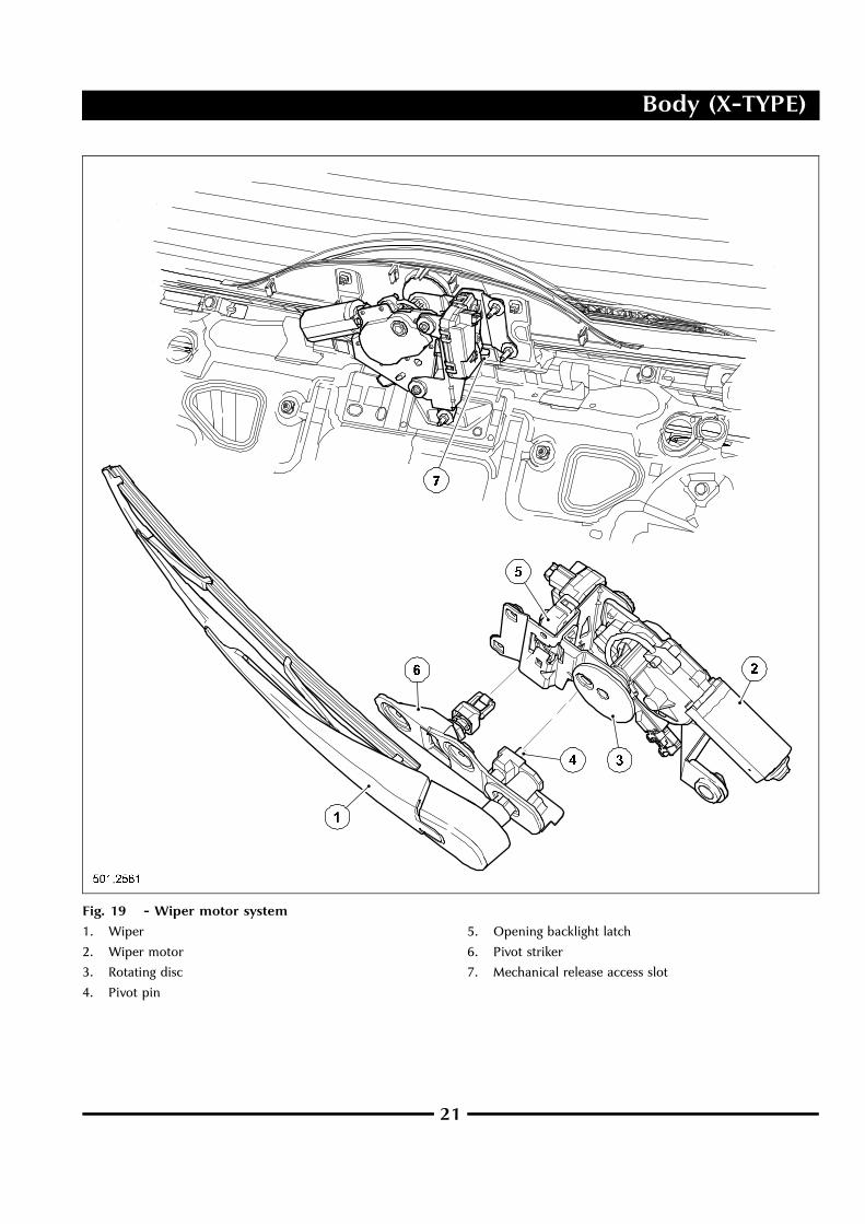
Rear Wiper System (Estate)The wiper in the rear wiper system is mounted on the openingbacklight and the motor is mounted in the lower tailgate.When the backlight is closed, a pin in the wiper arm engagesin a slot in the motor’s rotating disc.
A slot on the backlight latch, gives access to a mechanicalrelease in the event of electrical failure.
20
Body (X-TYPE)
Fig. 19 - Wiper motor system
1. Wiper
2. Wiper motor
3. Rotating disc
4. Pivot pin
5. Opening backlight latch
6. Pivot striker
7. Mechanical release access slot
21

Body (X-TYPE)
The wiper reservoir on the estate has a twin pump to feedthe front and rear wash/wipe. To supply the rear wash/wipe,the washer tube is routed to the rear to emerge at the nozzle,located on the rear spoiler.
Fig. 20 Washer reservoir and washer tube routing to rear
22

Body (X-TYPE)
Exterior Trim Components (Estate)There are several components unique to the estate shown inthe illustration below.
Fig. 21 Exterior trim components
1. Roof rear spoiler
2. Roof rails
3. Roof moulding
4. Quarter glass and fixings
5. ‘C’ and ‘D’ pillar cappings and rear door upper moulding
6. Sixth light
7. Rear bumper
8. Rear lamp cover
9. Rear lamp
23

Body (X-TYPE)
Roof Rear Spoiler
The roof rear spoiler is a painted plastic component fittedto the metal structure of the opening backlight by five M6nuts. The centre highmounted stop lamp (CHMSL) andwashernozzle are incorporated into the roof rear spoiler. To gainaccess to the CHMSL, interior trim and the spoiler need tobe removed.
Fig. 22 Roof rear spoiler, CHMSL and washer
1. Roof rear spoiler
2. Rear washer nozzle
3. CHMSL
24

Body (X-TYPE)
Roof Moulding and Roof Rails
The roof ditch mouldings have the same sections as the sedanbut with a clipping feature. All moulding are low gloss blackand are divided into two parts: front and rear. The roof railsmust be removed before the mouldings can be removed.
The roof rails are a standard fit on all estate vehicles. Black roofbars are standard fitment (silver painted bars are optional).They are fitted to the outside of the vehicle with twoM8 screwson each of the four feet. A plastic cover that requires a specialtool for removal, surrounds each foot.
Fig. 23 Roof rail detail
1. Roof rail foot
2. Roof rail foot cover
3. M8 bolt
‘D’ and ‘C’ Pillar Cappings and Rear Door UpperMoulding
The components are fixed with rivets, similar to the sedan.The ‘C’ pillar capping is 2mm longer than the sedan version.The ‘D’ capping is new and unique to the estate. The rear doorupper moulding is a straight profile to suit the line of the estatebut the moulding’s section is the same as the sedan.
Rear Lamp Shield
The rear lamps are new and fixed with four M6 nuts (thesame type as on the sedan). The tail lamps have a plasticshield located directly to the side of the lampwith plastic clips;the shield profile covers and matches the body-in-white (BIW)profile.
Rear Bumper and Beam (Estate)The rear bumper and beam are new to suit the new body styleand crash requirements. The rear beam fixings are carry-overfrom the sedan version but the beam is a different shape dueto a cut-out in the corner.
The rear bumper fixings are the same as the sedan with thefollowing exceptions:
• To improve the match with the tail lamp, two more fixingsare added in the center bracket.
• On the right-hand side, two fixings instead of one are fittedthrough the wheel arch area.
25

Body (X-TYPE)
Body System Interior
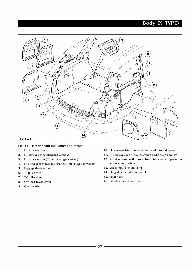
Luggage Compartment Trim (Estate)The headlining is new to fit the extended roof-line of theestate. The new luggage compartment floor trim and sidemouldings are shown on the illustration. Behind the left-handstowage door are three trim panel versions:
• Standard version for stowage space
• CD version with a slot for the CD autochanger
• CD and navigation version with a slot for the CDautochanger and the navigation unit.
The right-hand stowage door is fitted to non-premium audiosound system versions. Premium audio sound system modelshave the stowage door substituted by a cover holding a basssub-woofer speaker.
Four tie-down metal loops are positioned in the luggagecompartment. The loops are hinged and fold flat when notrequired.
26
Body (X-TYPE)
Fig. 24 Interior trim mouldings and carpet
1. LH stowage door
2. LH stowage trim (standard version)
3. LH stowage trim (CD autochanger version)
4. LH stowage trim (CD autochanger and navigation version)
5. Luggage tie-down loop
6. ‘E’ pillar trim
7. ‘D’ pillar trim
8. Seat belt tower cover
9. Quarter trim
10. LH stowage trim: non-premium audio sound system
11. RH stowage door: non-premium audio sound system
12. RH side cover with bass sub-woofer speaker: premiumaudio sound system
13. Waist moulding and lamp
14. Hinged carpeted floor panel
15. Scuff plate
16. Fixed carpeted floor panel
27

Body (X-TYPE)
Tailgate Trim (Estate)The tailgate interior trim comprises: upper interior moulding;lower moulding; side interior moulding; carpet insert; glassmoulding and glass wiper motor cover. On the exterior side
of the tailgate, but interior to the opening backlight, thereare three trim items: upper exterior moulding; side interiormoulding; wiper motor cover.
Fig. 25 Tailgate trim
1. Lower interior moulding
2. Carpet insert
3. Side interior moulding
4. Upper interior moulding
5. Side exterior moulding
6. Upper exterior moulding
7. Opening backlight moulding
8. Opening backlight wiper motor cover
9. Tailgate wiper motor cover
10. Latch bezel
28
Body (X-TYPE)
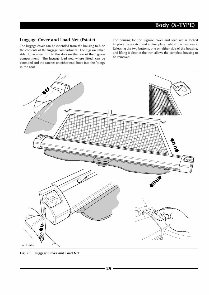
Luggage Cover and Load Net (Estate)The luggage cover can be extended from the housing to hidethe contents of the luggage compartment. The lugs on eitherside of the cover fit into the slots on the rear of the luggagecompartment. The luggage load net, where fitted, can beextended and the catches on either end, hook into the fittingsin the roof.
The housing for the luggage cover and load net is lockedin place by a catch and striker plate behind the rear seats.Releasing the two buttons, one on either side of the housing,and lifting it clear of the trim allows the complete housing tobe removed.
Fig. 26 Luggage Cover and Load Net
29

Body (X-TYPE)
Underfloor Storage
The underfloor storage tray is located below the luggagecompartment floor panel. To access the storage tray, lift thehandle on the rear edge of the floor panel. A retaining strapis fitted to the floor panel, which can be hooked over the toplip of the luggage compartment opening, to hold the floorpanel up when accessing the storage tray.
Fig. 27 - Underfloor storage tray
30
Body (X-TYPE)
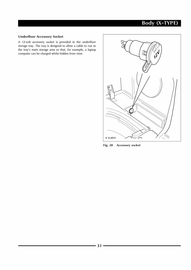
Underfloor Accessory Socket
A 12-volt accessory socket is provided in the underfloorstorage tray. The tray is designed to allow a cable to run tothe tray’s main storage area so that, for example, a laptopcomputer can be charged whilst hidden from view.
Fig. 28 Accessory socket
31
Body (X-TYPE)
Seating
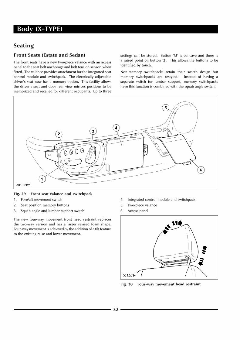
Front Seats (Estate and Sedan)The front seats have a new two-piece valance with an accesspanel to the seat belt anchorage and belt tension sensor, whenfitted. The valance provides attachment for the integrated seatcontrol module and switchpack. The electrically adjustabledriver’s seat now has a memory option. This facility allowsthe driver’s seat and door rear view mirrors positions to bememorized and recalled for different occupants. Up to three
settings can be stored. Button ’M’ is concave and there isa raised point on button ’2’. This allows the buttons to beidentified by touch.
Non-memory switchpacks retain their switch design butmemory switchpacks are restyled. Instead of having aseparate switch for lumbar support, memory switchpackshave this function is combined with the squab angle switch.
Fig. 29 Front seat valance and switchpack
1. Fore/aft movement switch
2. Seat position memory buttons
3. Squab angle and lumbar support switch
4. Integrated control module and switchpack
5. Two-piece valance
6. Access panel
The new four-way movement front head restraint replacesthe two-way version and has a larger revised foam shape.Four-waymovement is achieved by the addition of a tilt featureto the existing raise and lower movement.
Fig. 30 Four-way movement head restraint
32

Body (X-TYPE)
Rear Seats (Estate)The new 30/70 split rear seats provide a perceived flat loadfloor when folded, without needing to remove the headrests,except when a front seat is in its rearmost position. The
outboard headrests and the seat cushion are carry-over fromthe sedan but the center headrest is new. The squab releasecatches, located on the top of each seat back, and squablatching mechanism, are unique to the estate.
Fig. 31 - Rear seat
1. Release catch
2. New center headrest
3. Squab striker
4. Squab latch
33

Occupant Safety (X-TYPE)
Advanced Restraints System
Restraints Control Module (Estate andSedan)With certain modifications made to the advanced restraintssystem, the systems diagram below, provides an indication ofhow the electrical component parts interact with each other.
Fig. 32 Restraints control system block diagram
34
Occupant Safety (X-TYPE)
Key to Fig. 32
1. Crash sensing
2. Front crash sensor
3. Driver’s seat track position sensor
4. Passenger’s seat track position sensor
5. Driver’s front side-crash sensor
6. Passenger’s front side-crash sensor
7. Driver’s seat belt buckle switch
8. Passenger’s seat belt buckle switch
9. Driver’s rear side-crash sensor
10. Passenger’s rear side-crash sensor
11. Passenger’s belt tension sensor
12. Passenger’s seat weight-sensing system
13. Control and processing
14. Restraints control module
15. Diagnostic connector
16. Driver’s dual stage air bag (via clockspring)
17. Passenger’s dual stage air bag
18. Driver’s side air bag
19. Passenger’s side air bag
20. Driver’s front buckle pre-tensioner
21. Passenger’s front buckle pre-tensioner
22. Driver’s front reel pre-tensioner
23. Passenger’s front reel pre-tensioner
24. Driver’s side curtain air bag
25. Passenger’s side curtain air bag
26. Driver’s lower air bag
27. Protection
28. General electronic control module
29. Audible warning tone speaker (buckle status andsecondary warning indicator)
30. Supplementary restraints system (SRS) indicator lamp
31. Passenger’s air bag deactivation lamp
32. Warning
NOTE: Driver’s lower air bag is on all wheel drive vehicles.Belt tension sensor and driver’s and passenger’s reelpre-tensioner are on NAS vehicles.
Sensors (Estate and Sedan)
Belt Tension Sensor
A seat belt tension sensor (BTS) will be introduced in NASmarkets as a running change. It is stitched into the end ofthe passenger seat belt and attached to the seat belt anchor;incorporated is a harness connector.
The belt tension sensor is a strain-gauge type. The sensorconverts the force applied to the belt into an electrical signal.In the event that a child-seat is installed onto the front
passenger seat (not recommended), the force applied to thepassenger safety belt is reflected by the output signal fromthe sensor, which provides data to supplement that receivedfrom the silicon bladder. The passenger seat weight-sensingmodule, processes the input data and makes it availableto the restraints control module (RCM), which then makesthe necessary adjustments in respect of passenger air bagdeployment.
Retractor Pre-tensioner
For vehicles in certain markets, pyrotechnic pre-tensioners arelocated at the retractor, as well as the buckle. Pre-tensionersare designed to remove excess webbing in the event of a crash.They deploy very quickly and early on in the crash before theoccupant starts loading the safety belt.
35

Occupant Safety (X-TYPE)
Fig. 33 Front seat belt with pre-tensioner and belt tensioner sensor
1. Retractor with pyrotechnic pre-tensioner
2. Belt tension sensor connector
3. Passenger belt anchorage with belt tension sensor
36

Occupant Safety (X-TYPE)
Seat Track Position Sensor
A front passenger’s seat-track position sensor is introducedwhich is similar to the existing driver’s side and is locatedon the seat track. There are two versions: one for 8-waymovement seats and one for the 10-way movement seats.
The sensor is actuated by the magnet that is attached to theseat slide. The magnetic field disturbance caused when the
magnet passes the sensor, creates an output signal for theRCM. On receipt of this signal, which indicates when the seatis forward of a defined point in its travel, the RCM disables thesecond stage output of the driver air bag. Malfunction of thesensor or associated circuits will cause the SRS indicator lampto illuminate. Diagnosis must be undertaken using WDS.
Fig. 34 Front passenger seat track position sensor
1. Hall effect sensor 2. Steel bracket
37

Occupant Safety (X-TYPE)
Seat Weight Sensor
The seat weight sensor, part of the passenger seat weightsensing system, is replaced with a new GEN2 weight sensor.
Fig. 35 Seat weight sensor
38

Occupant Safety (X-TYPE)
Rear Safety Belts (Estate)Due to the absence of a rear parcel shelf on the estate, the rearouter seat belt retractors are mounted to the wheel housingquarter strengtheners (turrets). The center belt retractor ismounted inside the seat squab.
Fig. 36 Rear safety belts
39

Occupant Safety (X-TYPE)
Child Restraint Top Tether Anchorages (CanadianMarket)
Rear seats for the Canadian market have top tether anchoragesfitted to the rear of the squab, one for each seat position.Should a child seat with a top tether be fitted into the vehicle,the top tether must not be routed over the luggage cover. Itmust pass between the luggage cover and the seat back.
Fig. 37 Child restraint top tether anchorage
Driver Air Bag Module (Estate and Sedan)WARNING: Before commencing work on any part ofthe restraint system, the vehicle battery should bedisconnected and a period of at least one minuteallowed to elapse.
NOTE: The driver air bag module is a snap-fit design. Accessto release the snap-wire is through the service apertures; referto ‘JTIS / GTR’.
The module is a unique style designed to suit the new steeringwheel; refer to ‘JTIS / GTR’.
The driver air bag module is controlled by the restraintscontrol module (RCM), which chooses between first orsecond stage deployment, depending on driver seat buckleusage, the seat position and crash severity.
Variation in driver air bag deployment is determined by thetiming of the first and second stage ignition signals. Thisfacilitates adaptation of the stiffness and timing of the air bagto optimize occupant protection.
The module comprises:
• A twin stage inflator.
• Separate chambers for the two inflation stages, eachindependently activated by the RCM.
• Two air bag connectors that have fool-proof mechanicalkeying and are color-coded to the respective plug on theinflator.
• A non-azide propellant that reduces particulates andeffluents.
The air bag deploys radially, to reduce the risk of air baginduced injury to a driver that is positioned close to thesteering wheel.
Disposal of twin stage air bags is different to single stage airbags; refer to ‘JTIS / GTR’.
Fig. 38 Driver air bag service apertures
40

Occupant Safety (X-TYPE)
Fig. 39 Snap-wire - driver air bag module
Passenger Air Bag Deployment Door —NAS only (Estate and Sedan)In addition to the lens that displays the air bag deactivatedsymbol, the deployment door now carries the wording ‘PASSAIR BAG OFF’.
Fig. 40 Passenger air bag deployment door
41

Occupant Safety (X-TYPE)
Side Curtain Air Bag (Estate)Whereas the side curtain inflator in the sedan is routed fromthe roof-line down the ‘D’ pillar, for the estate the route forthe inflator remains at roof level.
Fig. 41 Side curtain air bag routing - estate
42

Occupant Safety (X-TYPE)
Driver Lower Air Bag Module (Estate andSedan)On all-wheel-drive vehicles (2.5 and 3.0L), an inflatable lowerair bag module replaces the driver’s side bolster panel. Thishas necessitated deletion of the stowage box. The instrumentpanel is derivatized to accommodate the driver lower air bagmodule with an adapter plate in lieu of a bolster plate.
The inflatable lower air bag module has one electricalconnector and has single stage inflation.
The same safe working procedures apply to this air bag as toany other air bag fitted to the vehicle. Refer to ‘JTIS / GTR’.
WARNING: Before commencing work on any part ofthe restraint system, the vehicle battery should bedisconnected and a period of at least one minuteallowed to elapse.
Fig. 42 Driver lower air bag module
43

Chassis (S-TYPE)
Brake System
Electric Park BrakeThe park brake switch has three positions, Apply, Release andIdle, and is hard wired to a new control module. The switchis fitted with double contacts for increased robustness.
The Electronic Control Module is mounted in the luggagecompartment, using a new mounting bracket. This modulenow connects directly to the CAN network, which haseliminated the gateway delay between the CAN and SCPnetworks.
Fig. 43 Electronic park brake module
1. Mounting bracket
2. Electronic control module
The park brake is applied using a cable mechanism, which isoperated by an actuator fitted to the rear sub-frame.
• Naturally aspirated variants use the existing rear brakecalipers.
• Supercharged variants use dedicated park brake calipers.
A new In-Gear Switch is fitted to the manual transmission toprovide the Drive Away Release feature.
The system provides enhanced diagnostic trouble code (DTC)coverage and diagnostics.
Function
Manual Apply:
The park brake is applied manually by lifting the consoleswitch. Manual application can be effected either when thevehicle is stationary or when in motion.
The application process of the park brake varies, controlled bythe Park Brake Module, depending on whether the vehicle isstationary or in motion.
Static Apply (speed less than 3 km/h):
• The park brake is applied to full force within one second ofactivating the switch.
Dynamic Apply - Low Speed (speed less than 32 km/h):
• Momentary switch activation - the park brake is applied for1/4 second.
• Continuous switch activation - the park brake is applieduntil the switch is released or until completion of the applycycle.
Dynamic Apply - High Speed (speed greater than 32 km/h):
A series of pre-determined on-off pulses is provided,approaching full braking force over a period of approximatelytwo seconds.
Audio and visual warnings are provided if the park brake isapplied whilst the vehicle is in motion.
Manual Release:
The park brake is released manually by pushing down theconsole switch.
44
Chassis (S-TYPE)
Automatic Apply:
Key Out Apply - the park brake is applied automatically whenthe ignition key is removed.
Automatic Release:
Drive Away Release:
• The park brake is released automatically on interpretationof the movement of the accelerator pedal, combined withinformation from the inclination sensor (vehicles withautomatic transmission).
• The release action has been calibrated to allow drivingaway, without rolling back, on an incline of up to 1:3.
Shift From Park Release:
• The park brake is released automatically when a gear isselected, without the engine running.
Service Mode
The Service Modemust be activated (using WDS) to service therear calipers, cables and actuator. This allows decoupling ofthe components and prevention of accidental damage to theactuator.
The park brake switch functions will be inhibited.
Service Bay Diagnostics
The following service bay diagnostics are available:
• Data Logger - Time base graphical representation of PIDvalues
• DTC Monitor - DTC retrieval and pinpoint test
• Guided - Diagnosis of individual component
• System / Sub-System test selection menu
• New symptom based test selection menu
• Configuration - Dealer configuration for replacementmodules.
On Board Diagnostics
Diagnostic trouble codes (DTC) are provided as follows:
• DTC - Fault code coverage for module inputs/outputs.
• DTC Snapshot - Status capture of relevant parameters whenfault code logs.
• Self Test - On Demand Self Test for system functional check.
Service Parts
The following parts will be available to service the parkingbrake system:
• Actuator assembly - serviced as complete unit.
• Two rear cables - a dedicated service tool is required torelease the cable tension.
• Electronic control module.
• Switch assembly and harness link to module.
• Separate park brake calipers on supercharged vehicles.
45

Chassis (S-TYPE)
Steering System
Power Assisted Steering SystemThe system used is the same as that used on previous models,but with the following change.
LHD vehicles:
• Electrical transducer rotated by 180 .
The fixings and torque figures are all carry-over.
46

Powertrain (S-TYPE)
Evaporative Emissions
Features of the NAS Carbon Can• New brackets front and rear to suit the Level II mounting
system.
• New bleed can.
• No items are serviceable separately.
Features of the ROW Carbon Can• New brackets front and rear to suit the Level II mounting
system.
• No items serviceable separately.
For fuel delivery information; refer to Fuel Tank and Lines.
Fig. 44 NAS carbon can
1. Filter
2. Mounting bracket
3. Canister close valve
4. Dust box
5. Pipe to fuel tank
6. Carbon can
47

Powertrain (S-TYPE)
Fuel Tank and LinesModifications and improvements to the fuel system have beenincorporated, mainly, but not only, to conform to the latestNAS requirements.
It is a NAS requirement that vehicles must comply to theimproved Level II evaporative emissions requirements by2005 MY.
Introduction by Jaguar is required by January 2004.
Requirements are that the system should have reducedemissions (Jaguar target 330 mg) and 15 years/150,000 miledurability.
Changes to the fuel system, based on the information givenabove, are as follows:
• New NAS fuel tank with improved sealing systems.
• New carbon can assembly with bleed trap. The ROWcarbon can has changed to suit the new mounting system.Refer to Evaporative Emissions.
• New stainless steel filler neck to satisfy 15 year durabilityrequirement. (NAS and ROW).
• New fuel lines with reduced number of joints. (NAS andROW).
Features of the Fuel TankNew valve cluster with improved sealing system.
New fuel delivery modules with improved sealing system andtank drain ports.
Serviceable parts:
• Fuel delivery modules.
• Tank assembly.
48

Powertrain (S-TYPE)
Fig. 45 Fuel system (supercharged)
1. Fuel pump and sender unit
2. Fuel tank
3. Hose to filler neck
4. Pressure control valve
5. Pipe to carbon can
6. Fuel pump and sender unit
7. Fuel filter
8. Fuel pipes to engine
49

Powertrain (S-TYPE)
Features of the Fuel Filler Neck• Stainless steel construction.
• New fixing arrangement to accommodate the new fillerbowl.
• New low permeation hose, filler neck to tank.
• New filler cap (as X-TYPE Level II).
• New vapor line to eliminate joints in the wheel arch area.
Fig. 46 Fuel filler neck
1. Hose to fuel tank
2. Stainless steel filler neck
3. Filler neck bowl
4. Vapor pipe
50

Powertrain (S-TYPE)
Vehicle Speed Control
Adaptive Cruise ControlThe adaptive cruise control (ACC) is an enhancement ofconventional cruise control, which helps the driver tomaintain a constant headway from the vehicle in front.
The driver inputs a desired cruising speed and engages thesystem, in the same way as he would for conventional cruisecontrol.
The system will then cruise at this set speed until anotherslower moving vehicle is detected in front. In this situationthe system will operate the throttle and brakes to maintain aconstant time based gap (headway) to the vehicle in front.
When using ACC, a chime will sound during circumstanceswhen the driver is required to intervene. These circumstancesmay require the driver to apply more braking effort than theACC is capable of applying. The ACC sounds the chime towarnthe driver, based on the range of the followed vehicle and therate at which the host vehicle is approaching that vehicle.
The new system is designated as ACC-3 whereas the previoussystem was ACC-2.
Functionality is the same as for ACC-2.
Forward Alert
Forward alert is a feature that allows the ACC module,independently of the ACC being set, to continue to monitorthe traffic and invoke the ’driver intervene’ chime and warningmessage.
The driver can select the sensitivity of when the chime sounds.The chime will sound when the threshold selected by thedriver is exceeded.
The ’Forward Alert’ switch enables the user to have this featureswitched ON or OFF.
Forward alert will not respond to stationary targets.
Differences Between ACC-2 and ACC-3
The new system (ACC-3) has a separate Forward LookingSensor and a separate controller: adaptive cruise controlmodule (ACCM), as opposed to the previous system (ACC-2)which combined the radar and controller in a single package.
The Forward Looking Sensor is located at the front of vehiclein the same location as the ACC-2 radar.
The ACCM is now located behind the fascia panel.
The instrument cluster now shows:
• ’Cruise On’ icon display.
• ACC-3 dedicated message centre in the speedometer.
• Chime module incorporated in the cluster.
Changes have been made to the messaging strategy.
Improvements to the performance and sensitivity of thesystem have been incorporated.
51

Powertrain (S-TYPE)
Fig. 47 Adaptive cruise control - main components
1. Sensor
2. Adaptive Cruise Control Module
3. Forward Alert On/Off switch
52

Electrical (S-TYPE)
Instrumentation and Warning Systems
Instrument ClusterA new instrument cluster has been designed having thefollowing redesigned features - two message centres, allillumination of the instruments and warning lamps is nowby light emitting diodes (LED), new chime unit and newautolamp calibration procedure (automatic). The slimmercluster package facilitates removal of the cluster in service.Each of these new features is described as follows:
New Features
Two message centres:
• Allows full time display of the clock and the odometer withthe ignition on. The clock is displayed in the speedometermessage centre and the odometer is displayed in thetachometer message centre.
• Allows concurrent display of the trip or warninginformation (tachometer display) at the same time asACC/cruise information (speedometer display).
• Used to indicate electric park brake status with ignition off.
All illumination now by LED:
• Greater reliability.
• No bulbs, therefore no serviceable lighting within thecluster.
Chime unit:
• Improvement to volume capability.
• Improvement to sound quality.
• Used to generate warning tones for the adaptive cruisecontrol (ACC).
• Used to generate warning tones for the Front Parking Aid.
Autolamp Calibration:
• Addresses the problem of some vehicles having oscillatingoutput around dawn/dusk.
• Addresses the problem of some vehicles having early turnon/late turn off.
Fig. 48 Instrument cluster
1. Engine coolant temperature
2. Tachometer
3. Speedometer
4. Fuel level
5. Message centre, clock and ACC/Cruise information
6. Message centre, odometer, and trip computer
53

Electrical (S-TYPE)
Parking AidThe parking aid is an optional convenience feature. It isavailable in two options:
• Reverse Parking Aid (Rear Only).
• Parking Aid (Front and Rear).
The system performs the same function as on the previousmodels, with following modifications:
• Improved visual integration of the distance sensors into thebumper.
• A new, configurable Park Aid Module.
• A new switch and warning LED in the overhead console, tocontrol the front parking aid. The rear parking aid operateswhen Reverse gear is selected.
Fig. 49 Overhead console
1. Overhead console
2. Front parking aid switch
54

Electrical (S-TYPE)
Lighting
Exterior LightingA new side marker / reflex and new front fog lamps are fittedto accommodate the change in profile of the bumpers.
A new rear lamp assembly is fitted to accommodate the changein profile of the rear body panels.
55

Electrical (S-TYPE)
Battery and Charging Systems
Battery CableThe battery cable performs the normal two functions, namelyto provide power from the battery to the starter motor and toprovide power from the alternator to charge the battery.
At the front bulkhead, it connects to an in-line junction box,located under a gusset panel.
The cable is covered by the undertray and by the wheel archliners. A protective cover is fitted over the cable, adjacent tothe rear jacking point.
Battery Cable Fitting Points
The vehicle must be raised.
All clips must be fitted to secure the cable to the under side ofthe vehicle.
The grommets in the wheel arches and panels must be fitted.
No special tools are required.
Significant Care Points
Extra care should be taken when routing the cable next to thejacking point on the front and rear of the RHS sill.
The harness must be hidden behind the undertray.
The jacking shield, adjacent to the rear jacking point, MUSTbe fitted to protect the cable.
Routing
The cable route is under the floor on the RHS of vehicle, fromthe megafuse in the luggage compartment, around the rearwheel arch, to under the front bulkhead.
56

Electrical (S-TYPE)
Fig. 50 Battery cable route
1. In-line junction box
2. Battery cable
3. Jacking shield
4. Grommet in wheel arch
5. Megafuse
6. Battery
57

Electrical (S-TYPE)
Electronic Feature Group
V60 Telephone - NASThe V60 portable replaces the previous Timeport phone. It isstored in a new hang up cup in the centre console.
It is based on current Motorola aftermarket products, but withunique Jaguar software.
Two derivatives of dual mode mobile phone (digital &analogue) are available, CDMA and TDMA.
There is a new communications bus between the handset andthe control module.
The in-vehicle functions and the diagnostics are all carry over.
Phone System
Only a Jaguar Retailer can install the phone system. However,every vehicle is pre-wired to accommodate the fitting of thesystem.
Operation of the telephone is by use of any of the following:
• The phone handset.
• Audio panel.
• Steering wheel switches.
• Touch screen (where fitted).
• Voice activation (US English) (where fitted).
Comprehensive onboard diagnostics are provided to self-testfor possible faults in the circuits.
Control Module
The control module is located in the left hand side of theluggage compartment. It has one electrical connector and oneD2B optical connector.
The control module is unique to Jaguar, but utilizes carry overhardware.
Microphone
The microphone is integrated into the roof console.
Antenna
The antenna (patch) is mounted on the rear bumper.
58

Body (S-TYPE)
Body System ExteriorThe body side panels and the lower back are the mainmodifications to the vehicle body shell to suit the new style.
The main changes are listed below and shown on theillustration Fig. 51.
• Body side panel.
• Rear lamp mounting panels (part of the body side panel).
• Lower back panel.
• Dash panel.
• Radiator support assembly.
• Bracket - rear floor panel to quarter panel.
Panels not illustrated:
• Floor centre panel.
New bumper mounting brackets have been designed to matchthe profile of the restyled bumpers.
The crash sensor has been repositioned to mount directly onto the rear face of the beam.
Changes to other panels are described in the following subsections.
Fig. 51 New body panels
1. Bracket - rear floor panel to quarter panel
2. Radiator support assembly
3. Dash panel
4. Body side panel
5. Rear lamp mounting panel (part of side panel)
6. Lower back panel
59
Body (S-TYPE)
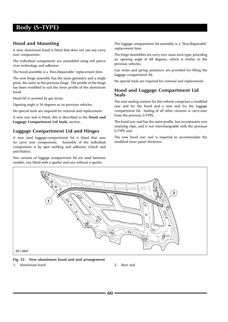
Hood and MountingA new, aluminium hood is fitted that does not use any carryover components.
The individual components are assembled using self piercerivet technology and adhesive.
The hood assembly is a ’Non-Repairable’ replacement item.
The new hinge assembly has the same geometry and a singlepivot, the same as the previous hinge. The profile of the hingehas been modified to suit the inner profile of the aluminiumhood.
Hood lift is assisted by gas struts.
Opening angle is 54 degrees as on previous vehicles.
No special tools are required for removal and replacement.
A new rear seal is fitted, this is described in the Hood andLuggage Compartment Lid Seals, section.
Luggage Compartment Lid and HingesA new steel luggage-compartment lid is fitted that usesno carry over components. Assembly of the individualcomponents is by spot welding and adhesive (clinch andanti-flutter).
Two variants of luggage compartment lid are used betweenmodels, one fitted with a spoiler and one without a spoiler.
The luggage compartment lid assembly is a ’Non-Repairable’replacement item.
The hinge assemblies are carry over swan neck type, providingan opening angle of 68 degrees, which is similar to theprevious vehicles.
Gas struts and spring assistance are provided for lifting theluggage compartment lid.
No special tools are required for removal and replacement.
Hood and Luggage Compartment LidSealsThe new sealing content for this vehicle comprises a modifiedrear seal for the hood and a new seal for the luggagecompartment lid. Sealing of all other closures is carry-overfrom the previous S-TYPE.
The hood rear seal has the same profile, but incorporates newretaining clips, and is not interchangeable with the previousS-TYPE seal.
The new hood rear seal is required to accommodate themodified inner panel thickness.
Fig. 52 New aluminium hood and seal arrangement
1. Aluminium hood 2. Rear seal
60

Body (S-TYPE)
The new luggage compartment lid seal is required to:
• Accommodate the new body side and luggagecompartment lid profiles.
• Provide a trim flip to cover the edge of the new scuff plateand luggage compartment carpet.
Fig. 53 New steel luggage compartment lid and seal
1. New seal
2. New steel luggage-compartment lid
Luggage compartment lid seal specification:
• EPDM and sponge extrusion.
• Wire carrier in place of lanced steel (increased flexibility).
• Mastic in the root of the seal, for sealing against water leaks.
• More flexible than the previous seal, to aid refitting.
• Visual aid (paint dot) to help in the correct alignment whenrefitting.
• A built-in flap to cover the fixed trim panel.
The new luggage-compartment lid seal is not interchangeablewith the previous S-TYPE seal.
No special tools are required for removal and replacement ofeither seal.
Underbody Systems
Engine Undertray
There is a new undertray, manufactured using newblow-moulding technology.
It now includes side walls to reduce the effects of noise andvibration.
The fixing arrangement is the same as the previous S-TYPE.
61

Body (S-TYPE)
Front and Rear Bumper SystemsThe three versions of the bumper have been restyled and havean improved fixing strategy. The three versions are:
• Front bumper.
• Rear bumper.
• ‘R’ version bumper.
The front bumpers now include the incorporation of the frontparking aid (option) sensors, adaptive cruise control (ACC)sensor and ’common fit’ energy absorbers.
Fig. 54 Front bumper system - supercharged shown
1. Front bumper cover
2. Grille
3. Oil cooler mesh
4. New arrangement of mounting brackets
5. Isolating foam - LH and RH
6. Inserts to isolating foam
7. Bumper system main beam
8. Valance panel
62

Body (S-TYPE)
Fig. 55 Rear bumper system
1. Rear bumper cover
2. Towing eye cover
3. Bumper extension panel
4. Rear bumper mounting brackets
5. LH end beam isolator
6. Isolator foam
7. Bumper system main beam (carry over S-TYPE)
8. RH end beam isolator
NOTE: Items 5 to 8 are to NAS Specification.
Exterior TrimVarious items of exterior trim have been changed, both asdesign improvements and to accommodate the new bodystyling.
Wheel Arch Liners
The manufacturing process is by injection moulding.
They are a similar shape and size to the previous S-TYPE liners,but with reduced material thickness for weight optimization.
One variant only, fitted to all vehicle derivatives.
Radiator Sight Shield
Injection moulded, natural black grained plastic component.Nominally 2mm thick.
Similar shape to the previous S-TYPE, fitting across the car,above the headlamps.
It is retained by four push-in/screw-out (not turn) fir treescrivets as the previous S-TYPE. No special tools are required.
One variant only, fitted to all new S-TYPE derivatives.
63
Body (S-TYPE)
Corner Modules
Corner modules have similar geometry to the previous S-TYPEwith the main difference being the removal of the centersection.
Corner modules are situated between the front bumper beamand the cooling pack, and are used to set the alignment of thefront wings, lamps, grille and bumper.
Modules should only require replacement due to crashdamage.
One variant (per corner) for all new S-TYPE derivatives.
Front Grille
New style front grille in four variants:
• Classic grille - Dorchester grey vane pack with chromedbezel.
• Sport grille - Dorchester grey vane pack with painted bezel.
• ‘R’ grille - Stainless steel mesh with painted bezel.
• Highline grille - Dorchester grey vane pack with chromefront face with chromed bezel.
Fixings and torque figures are as previous S-TYPE grilleassembly.
Front Grille Badge
New style corporate front grille badge.
Removal as previous badges - heat and apply wire/line to breakseal.
New corporate growler to be mounted on revised radiatorgrille, not hood.
Hood Leaper
Although using a new hood, which is less convex, a carry-overleaper is used.
Secured with M16 plastic nut.
Sill Appliqué
Injectionmoulded plastic-color keyed. Using carry-over upperfixings and new longer, lower fixings.
Luggage Compartment Lid Finisher
The finisher is now full length and is manufactured usinginjection moulded plastic.
Options of chrome plated and painted are available.
The fixings are external, using four screws and two clips. Asmall Die-Cut piece of 3M tape is fitted to secure the last 70mm of each end of the finisher to the luggage compartmentlid.
There is a depression for emergency key access.
The release button is now on the underside.
Luggage Compartment Lid Spoiler
The new spoiler is a flexible single component part, not a rigidinjection moulded two piece assembly, as previously.
The new features are as follows:
• Flexible moulding.
• Fits within the confine of the luggage compartment lid.
• No interior fixing.
• Painted body color.
• Adhesive tape fix to body.
64

Body (S-TYPE)
Windscreen Wiper SystemThe wiper/washer system now incorporates the washer jets onthe wiper arm, similar to the current XJ vehicles. This providessignificantly better high speed washer performance.
The deletion of the hood mounted washer jets has providedan improved appearance to the hood and there is now norequirement to match the jets to the body color.
There has been no change to the wiper linkage and motor.
The arms and blades retain the same geometry, but:
• The blade clip has changed to a combined clip/jet, as XJ,and is pre-assembled to the blade.
• Jet clips are common to driver and passenger sides, but aredifferent LHD to RHD.
• The hose run is now along the arm assembly and a newhose retention clip, as XJ, is used.
• A hole in the head of the wiper arms allows passage of thehose and is of the same principle as the XJ.
Fig. 56 Windscreen wipers and washers (LHD shown. RHD symmetrically opposite)
1. Washer hose connects to hose feed from reservoir
2. Washer jet and blade retaining clip (Passenger side)
3. Washer hose
4. Washer jet and blade retaining clip (Driver side)
5. Washer hose
6. Hose - through wiper arm assembly (Driver side)
7. Hose - through wiper arm assembly (Passenger side)
8. Leaf shield
9. Hose assembly integral to leaf screen
65
Powertrain (XK)
Exhaust System
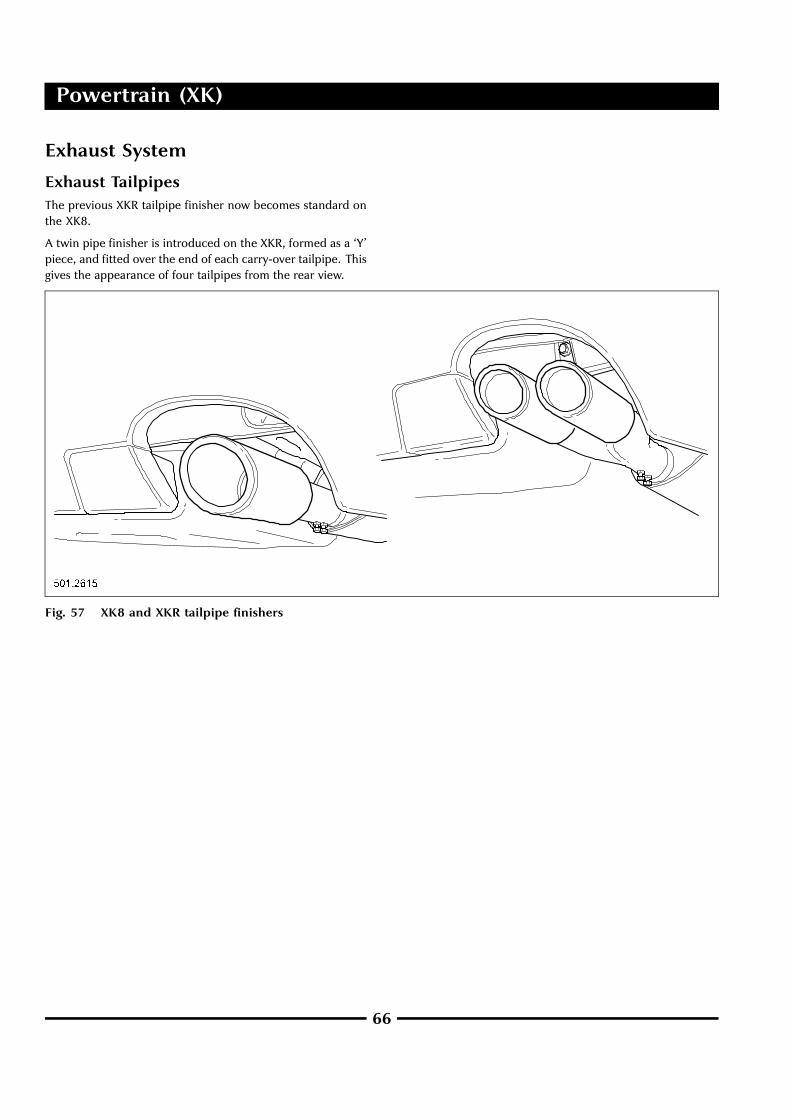
Exhaust TailpipesThe previous XKR tailpipe finisher now becomes standard onthe XK8.
A twin pipe finisher is introduced on the XKR, formed as a ‘Y’piece, and fitted over the end of each carry-over tailpipe. Thisgives the appearance of four tailpipes from the rear view.
Fig. 57 XK8 and XKR tailpipe finishers
66

Powertrain (XK)
For centralizing the tailpipe in the bumper aperture on XK8and XKR, an adjustable exhaust mounting system is provided.
Fig. 58 Adjustable exhaust mounting system
67

Powertrain (XK)
Vehicle Speed Control
Adaptive Cruise ControlThe adaptive cruise control (ACC) is updated from versionACC-2 to version ACC-3 but functions in the same way.The ACC-2 version had the radar sensor and the controlmodule as a single package mounted behind the bumpercover cooling aperture to provide a clear view forward for
the radar beam. The ACC-3 version retains the location forthe radar sensor but has a separate control module, locatedunderhood in the powertrain control module (PCM) cool box,next to the bulkhead. The ACC control module is securedwith self-adhesive Velcro.
Fig. 59 Radar sensor location
Fig. 60 Adaptive cruise control module location Fig. 61 Automatic speed limiter button
68

Powertrain (XK)
Fig. 62 Adaptive cruise control system interface schematic diagram
1. Forward alert switch
2. Adaptive cruise control module
3. Local controller area network (CAN)
4. Forward location sensor
Automatic Speed Limiter
The automatic speed limiter (ASL) can be used by the driverto select a maximum vehicle speed limit between the rangeof 30 km/h (18 mile/h) to 240 km/h (150 mile/h) that is not tobe exceeded. This is an additional feature that is interlockedwith the cruise (speed) control system. The switch on the ‘J’gate surround allows the driver to switch between the cruise(speed) control (or adaptive cruise control, where fitted)system and the automatic speed limiter system.
It is advisable to set the speed limit while the vehicle isstationary but with the engine running. When the ASL systemis switched on, the tell-tail status light will illuminate andthe ASL function will be selected. In the alternative switchposition, the light will be extinguished and the cruise (speed)control system will be selected.
When the ASL has been set, the engine will respond tothe driver’s accelerator pedal demand until the set limit isreached. At this point, provided that the accelerator pedalposition is sustained, the vehicle will maintain the limit speed.
The ASL system controls the vehicle speed through enginethrottle control to match the limit speed.
If the accelerator pedal is depressed further, the vehiclewill not increase speed but the automatic speed limiter willhold the vehicle to the limit speed. The ASL system can becancelled either by switching to cruise (speed) control orapplying kickdown on the accelerator pedal or by pressingthe CANCEL button on the steering wheel.
The application by the driver of the brakes will not deactivatethe ASL system. The system is deactivated and the limit speedmemory deleted, each time the ignition is switched off.
When ASL is selected, the message center will display one ofthe following:
• Limiter set.
• Limiter cancelled.
• Limiter not available.
• Too fast to resume limit.
• Over limit.
69

Body (XK)
Body System Exterior
Bumpers
Front Bumper Cover
The front bumper is deeper and includes the addition of alower ’mouth’. To compliment this, it has a feature creaseline on each side. The splitter vane on the normally aspiratedderivative now sits in line with and goes through the overridersinstead of sitting behind them. On the XKR, the mesh grille sitsin line with the front of the overriders, as opposed to havingthe overriders protrude through.
Fig. 63 New front bumper cover: XK8 and XKR
70

Body (XK)
Rear Bumper Cover
The rear bumper cover is also deeper and has larger cut-outsto accommodate the larger twin exhaust pipe finishers on theXKR. There is a new tow eye cover and on the opposite side ofthe bumper cover, groove lines take the shape of a false coverto give the bumper cover a symmetrical appearance. The sidesof the rear cover as they reach the wheelarches, are now flushto the rear fender panels (as opposed to the previous conditionwhere the rear cover sat inboard / underflush.
Fig. 64 New rear bumper cover and tow eye cover
71

Body (XK)
Sill AppliquéThe new sill appliqué adds depth to the side profile to give amore muscular impression. The sill appliqué is in two parts,with the longer part being able to slide over the shorter,to allow for expansion. The body side rubbing strips weredeleted at 2004 model year which adds further depth to theside profile appearance.
Fig. 65 Sill appliqué
72

Body (XK)
Rear SpoilersThe rear spoiler, previously fitted to the XKR, is now a standardfit to the XK8. A new spoiler is introduced for the XKR usingthe same locating holes and pegs as the previous spoiler.
Exterior Trim FinishersThe front and rear screen Dorchester finishers and otherDorchester trim, including the door mirrors, are now finishedin premium black (low gloss), in-lieu of Dorchester grey.
Fig. 66 XK8 spoiler and XKR spoiler
73

.

.

.
Published by Technical Communications, Jaguar Cars LimitedPublication Part No. JJM 18 15 99/50, January 2004


![Xk jkX]] KD spa opportunities · spa opportunities =`e[ ^i\Xk jkX]]KD 8 JG8 9LJ@E](https://static.documents.pub/doc/80x56/5ce97cf388c9931a558c1121/xk-jkx-kd-spa-spa-opportunities-e-ixk-jkxkd-8-jg8-9lje.jpg)


