50
IER 400B PRINTER User Guide N0C402B N0C402B - Rev. 1 July 6, 2009
IER 400BPRINTER
User GuideN0C402B
N0C402B - Rev. 1July 6, 2009

IER SIEGE - HEADQUARTERSIER S.A.3, rue Salomon de Rothschild92156 SURESNES CEDEXFRANCETel. +33 (0)1 41 38 60 00Fax +33 (0)1 41 38 62 75
IER dans le monde - IER Worldwide
CHINA
IER ShanghaiKuen Yang Plaza #1101798 Zhao Jia Bang RoadSHANGHAI 200030P.R.C.Phone: +86 (21) 6473 6792Fax: +86 (21) 6473 6806
GERMANY
IER GmbHWilhelm-Heinichen-Ring 429227 CellePhone: +49 (0) 5141/980 89 14Fax: +49 (0) 5141/980 89 20
SINGAPORE
IER PTE Ltd120 Lower Delta Road#14-13/16 Cendex CentreSINGAPORE 169208Phone: +65 6276 6966Fax: +65 6271 5563
SPAIN
IER Impresoras Especializadas, S.L.C/ Torre de Don Miguel, 23E-28031 - MADRIDPhone: +34 91 535 89 75Fax: +34 91 535 89 76
UNITED ARAB EMIRATES
IER DubaiPO Box 37585DUBAIPhone: +971 4 347 67 20Fax: +971 4 347 67 03
UNITED KINGDOM
IER LtdUnit G4Middlesex Business CentreBridge RoadSOUTHALL, MIDDX, UB2 4ABPhone: +44 (0)208 744 7650Fax: +44 (0)208 744 7670
UNITED STATES
IER Inc. Dallas2015 Midway Road, Suite 118CARROLLTON TX 75006Phone: +1 (972) 991 2292Fax: +1 (972) 991 1044Toll free: 1-800 624 8538
IER Inc. Belton815 Kirkley BlvdBELTON TX 76513Phone: +1 (254) 933 5000Fax: +1 (254)933 5050
IER 400BUser Guide
Page 2N0C402B Rev. 1July 6, 2009
Ce document est la propiété d'IER et ne doit pas être reproduit ou communiqué sans autorisation écrite.This document is the property of IER and may not be reproduced or communicated without prior written authorization

NOTICE
WARNING
THIS PRODUCT COMES WITH A LITHIUM BATTERY.BATTERY REPLACEMENT MUST IMPERATIVELY BEPERFORMED BY QUALIFIED MAINTENANCEPERSONNEL. MOREOVER, ONLY IER APPROVEDMODELS MAY BE USED.
WARNING
DANGER OF EXPLOSION IF BATTERY ISINCORRECTLY REPLACED. REPLACE ONLY WITH THESAME OR EQUIVALENT TYPE RECOMMENDED BY THEMANUFACTURER. DISPOSE OF USED BATTERIESACCORDING TO THE MANUFACTURER’SINSTRUCTIONS.
The United States Federal Communications Commission (in 47 CFR15.105) has specified that the following notice be brought to the attention ofusers of this product.
NOTE: This equipment has been tested and found to comply with the limitsfor a Class B digital device, pursuant to Part 15 of the FCC Rules. Theselimits are designed to provide reasonable protection against harmfulinterference in a residential installation. This equipment generates, usesand can radiate radio frequency energy and, if not installed and used inaccordance with the instructions, may cause harmful interference to radiocommunications. However, there is no guarantee that interference will notoccur in a particular installation.
If this equipment does cause harmful interference to radio or televisionreception, which can be determined by turning the equipment off and on,the user is encouraged to try to correct the interference by one or more ofthe following measures:- Reorient or relocate the receiving antenna.- Increase the separation between the equipment and receiver.- Connect the equipment into an outlet on a circuit different from that to
which the receiver is connected.- Consult the dealer or an experienced radio/TV technician for help.
In accordance with FCC requirements, changes or modifications not
IER 400BUser Guide
Ce document est la propiété d'IER et ne doit pas être reproduit ou communiqué sans autorisation écrite.This document is the property of IER and may not be reproduced or communicated without prior written authorization
Page 3N0C402B Rev. 1
July 6, 2009

expressly approved by IER could void the user's authority to operate thisproduct.
Use of a shielded cable is required to comply within Class B limits of Part15 of FCC Rules.
NORWAY: This product is also designed for IT power distributionsystem with phase-to-phase voltage 230V.
NORWAY & SWEDEN: Apparaten skall anslutas till jordat uttag närden ansluts till ett nätverk.
WARNING
THIS APPLIANCE MUST BE GROUNDED.THIS PRODUCT MUST EXCLUSIVELY BE CONNECTEDTO AN ELECTRICAL CIRCUIT THAT IS :- PROVIDED WITH A GROUND FAULT CIRCUIT
INTERRUPTER (GFCI) COMPLYING WITH IEC 364 ANDNFC15-100 REGULATIONS, AND
- CONFORMING WITH THE VOLTAGECHARACTERISTICS SPECIFIED BY THE NF EN 50160STANDARD.
The cover(s), door(s) and/or drawer(s) of this product is (are) intended foroccasional use and must be normally closed.
The warranty shall be null and void in case of use of any spare part, special tool orconsumable not expressly approved in writing by IER and in the event of attempted repair or
servicing of the machines by persons lacking the requisite technical qualifications.
This document contains proprietary information of IER. It may not be reproduced orcommunicated without prior written authorization of IER. It is intended solely for the
use of the product described herein, to the exclusion of any other usage.
It is provided as is, for information purposes only, without any warranty of any kind,including any warranty of fitness or a particular purpose, and may be modified by IER
at any time.
The information and specifications contained in this document are subject to changewithout prior notice.
Translated from French - IER Documentation Department
IER 400BUser Guide
Page 4N0C402B Rev. 1July 6, 2009
Ce document est la propiété d'IER et ne doit pas être reproduit ou communiqué sans autorisation écrite.This document is the property of IER and may not be reproduced or communicated without prior written authorization

In compliance with the European Directive 2002/96/CE relative to themanagement of Waste Electrical and Electronic Equipment (WEEE)implemented as of August 13, 2005, this product may not be disposed ofwith regular household waste. All products concerned by this directive aremarked with the above symbol.
The end owner of this product is responsible for either:Transferring the product to an authorized treatment facility where theproduct components, recognized to present a hazard to the environmentand/or public health, will be recycled and recovered properly, orConsulting with the manufacturer for appropriate product wastemanagement according to the terms of the manufacturer.
IER 400BUser Guide
Ce document est la propiété d'IER et ne doit pas être reproduit ou communiqué sans autorisation écrite.This document is the property of IER and may not be reproduced or communicated without prior written authorization
Page 5N0C402B Rev. 1
July 6, 2009
CONTENTS
1. GENERAL ................................................................ 81.1 CONTENTS OF SHIPPING CONTAINER ................................ 81.2 PRESENTATION OF THE PRINTER ...................................... 91.3 PRINTER DESCRIPTION ..................................................... 10
1.3.1 EXTERIOR FRONT VIEW......................................................... 101.3.2 EXTERIOR REAR VIEW........................................................... 121.3.3 INTERIOR VIEW OF PRINTER.................................................. 14
2. CONNECTING THE PRINTER AND POWER-UP.... 152.1 CONNECTING THE PRINTER............................................... 15
2.1.1 PROCEDURE ........................................................................ 152.1.1.1 Connecting the Printer to the AC Power ............. 162.1.1.2 Connecting the Printer to the Data
Communications System .................................... 182.2 POWERING UP THE IER 400 PRINTER............................... 20
2.2.1 PROCEDURE ........................................................................ 202.3 POWERING DOWN THE IER 400 PRINTER.......................... 21
2.3.1 PROCEDURE ........................................................................ 21
3. INSTALLING AND LOADING THECONSUMABLES...................................................... 223.1 OPENING THE PRINTER COVER......................................... 22
3.1.1 PRELIMINARY INFORMATION .................................................. 223.2 INSTALLING FANFOLD MEDIA............................................ 23
3.2.1 PROCEDURE ........................................................................ 233.3 INSTALLING ROLL MEDIA ................................................. 24
3.3.1 INSTALLING A ROLL OF DOCUMENTS...................................... 243.4 ADJUSTING THE PAPER PATH WIDTH................................ 26
3.4.1 PROCEDURE ........................................................................ 263.5 MEDIA LOADING............................................................... 29
3.5.1 PAPER LOAD PROCEDURE .................................................... 29
IER 400BUser Guide
Page 6N0C402B Rev. 1July 6, 2009
Ce document est la propiété d'IER et ne doit pas être reproduit ou communiqué sans autorisation écrite.This document is the property of IER and may not be reproduced or communicated without prior written authorization

4. PRINTER OPERATION............................................ 304.1 INDICATOR AND KEY FUNCTIONS ...................................... 30
4.1.1 MEANING OF PRINTER INDICATOR BEHAVIOR ......................... 304.1.2 CONTROL PANEL KEY FUNCTIONS......................................... 31
4.2 PRINTING DOCUMENTS...................................................... 324.2.1 DOCUMENT PRINTING PROCEDURE ........................................ 32
5. USER LEVEL TROUBLESHOOTING...................... 345.1 OPERATING FAULTS ........................................................ 34
5.1.1 WHEN POWERING UP, THE PRINTER DOES NOT START UP........ 345.1.2 THE PRINTER DOES NOT RECEIVE PRINT DATA........................ 345.1.3 THE PAPER IS NOT FEEDING................................................... 355.1.4 POOR PRINT QUALITY............................................................ 355.1.5 FREQUENT ERROR SIGNALS ................................................. 36
5.2 OPENING THE PRINTHEAD ASSEMBLY - CLEARING ADOCUMENT JAM............................................................... 385.2.1 PROCEDURE ........................................................................ 38
5.3 CLOSING AND LOCKING THE PRINTHEAD ASSEMBLY.......... 405.3.1 PROCEDURE ........................................................................ 40
5.4 UNLOADING THE MEDIA.................................................... 425.4.1 AUTOMATIC REMOVAL........................................................... 425.4.2 MANUAL REMOVAL ............................................................... 43
6. PRINTER MAINTENANCE....................................... 456.1 RECOMMENDED PERIODIC MAINTENANCE ......................... 45
6.1.1 PERIODIC MAINTENANCE FREQUENCY..................................... 456.2 PERIODIC MAINTENANCE PROCEDURES............................. 46
6.2.1 REMOVING DUST FROM THE PRINTER MECHANISM ................ 466.2.2 CLEANING THE PRINTHEAD AND PLATEN................................ 48
6.3 RESTORING THE PRINTER TO OPERATIONAL CONDITIONFOLLOWING PERIODIC MAINTENANCE................................ 506.3.1 ACTIONS TO BE PERFORMED BEFORE PUTTING THE PRINTER
INTO SERVICE ...................................................................... 50
IER 400BUser Guide
Ce document est la propiété d'IER et ne doit pas être reproduit ou communiqué sans autorisation écrite.This document is the property of IER and may not be reproduced or communicated without prior written authorization
Page 7N0C402B Rev. 1
July 6, 2009

1 GENERAL
1.1 CONTENTS OF SHIPPING CONTAINER
The box in which the printer is shipped contains:
an IER 400B Printer,a user safety guide,a power cord (optional),a set of test coupons, one of which contains the default (factory)configuration of the printer.
IMPORTANT: We recommend that you retain the packing material(box and padding) at least throughout the warrantyperiod.Also keep the User Safety Guide and the machineconfiguration coupon near to the printer.
Visit our website to download the PDF version of the User Guidewww.ier.fr
Figure 1.1Contents of printer shipping container
IER 400BUser Guide
Page 8N0C402B Rev. 1July 6, 2009
Ce document est la propiété d'IER et ne doit pas être reproduit ou communiqué sans autorisation écrite.This document is the property of IER and may not be reproduced or communicated without prior written authorization

1.2 PRESENTATION OF THE PRINTER
The IER 400B Printer is designed to print bag tags, ATB1 size couponsand flight strips.
With a standard print resolution of 203 dpi (8 dots/mm), the IER 400BPrinter provides high quality print for text, logos and barcodes.
In its 107mm printhead version (80mm on the standard version), theIER 400B Printer can print documents up to 120mm in width.
The printer can also be fitted with two different types of front panel:
a front panel with a display and a 4-key control panel,a front panel with no display and a 2-key control panel.
The IER 400B Printer uses direct thermal printing technology, whichrequires heat-sensitive paper media.
Blank bag tags or boarding pass strips are fed continuously through therear of the printer. The printer accepts fanfold media or roll media, if fittedwith the IER roll media dispenser option.
The printer is equipped as standard with an output slot with two serratededges for tearing off printed documents.
Optionally, the printer can feature an automatic document separatorsystem,
of the cutter type for applications requiring documents of varying lengths.
For applications offering RFID (Radio Frequency Identification)-enabledbaggage handling, the IER 400B Printer, if equipped with the optional RFIDmodule, is also able to print and encode bag tags containing a radiofrequency antenna.
IER 400BUser Guide
Ce document est la propiété d'IER et ne doit pas être reproduit ou communiqué sans autorisation écrite.This document is the property of IER and may not be reproduced or communicated without prior written authorization
Page 9N0C402B Rev. 1
July 6, 2009

1.3 PRINTER DESCRIPTION
1.3.1 Exterior Front View
The IER 400B Printer features:
On one version, a front panel equipped with a display (8) and a4-key control panel (1), see figure page 11.
The 4-key panel features:- an "ONLINE" key (2) to acknowledge a fault condition or to
toggle from one mode to another ("Offline" / "Online"),
- a "TEST" key (3) enabling the printout of test documents orthe selection of another application (if available),
- a "RESET" key (4) to clear faults,
- a "FEED" key (5) to eject a blank document,
- a red indicator lamp (6),
- a green indicator lamp (7).The activation and behavior of the indicators reflect theoperational status of the printer (see page 30) and the occurrenceof printing errors (see page 34).
On another version, a front panel with no display but a displaycover (16) and a 2-key control panel (11), see figure page 11.
The 2-key control panel (11) features only:- the "ONLINE" (12) and "TEST" (13) keys,
- the red (14) and green (15) indicator lamps.
An "RFID" sticker (17) indicating that the printer is equipped withthe RFID option (can be included with both versions).A paper ejection slot (9).A protective cover (10).
IER 400BUser Guide
Page 10N0C402B Rev. 1July 6, 2009
Ce document est la propiété d'IER et ne doit pas être reproduit ou communiqué sans autorisation écrite.This document is the property of IER and may not be reproduced or communicated without prior written authorization

1 - Control panel2 - Mode key3 - Test document key4 - Fault clear key5 - Eject blank document key
6 - Red indicator lamp7 - Green indicator lamp8 - Display9 - Ejection slot
10 - Protective cover
Figure 1.2Front view - Version: Front panel with display and 4-key control panel.
11 - Control panel12 - Mode key13 - Test document key14 - Red indicator lamp
15 - Green indicator lamp16 - Display cover17 - RFID sticker
Figure 1.3Front view - Version: Front panel without display and 2-key control
panel
IER 400BUser Guide
Ce document est la propiété d'IER et ne doit pas être reproduit ou communiqué sans autorisation écrite.This document is the property of IER and may not be reproduced or communicated without prior written authorization
Page 11N0C402B Rev. 1
July 6, 2009

1.3.2 Exterior Rear View
The rear of the IER 400B Printer features:The communications interface, including:
- an RJ45 network port (1),
- a USB port (2)
- an RS232 serial port (3), COM1,
- an RS232 serial port (4), COM2,
- a "Host" USB port (5).
Two locating pins (6) for the installation of the optional roll mediadispenser.AC power connector (7).AC power switch (8).
IER 400BUser Guide
Page 12N0C402B Rev. 1July 6, 2009
Ce document est la propiété d'IER et ne doit pas être reproduit ou communiqué sans autorisation écrite.This document is the property of IER and may not be reproduced or communicated without prior written authorization

1 - RJ45 network port2 - USB port3 - RS232 serial port (COM1)4 - RS232 serial port (COM2)
5 - "Host" USB port6 - Locating pins (roll media
dispenser)7 - AC power connector8 - AC power switch
Figure 1.4Rear View of Printer
IER 400BUser Guide
Ce document est la propiété d'IER et ne doit pas être reproduit ou communiqué sans autorisation écrite.This document is the property of IER and may not be reproduced or communicated without prior written authorization
Page 13N0C402B Rev. 1
July 6, 2009

1.3.3 Interior View of Printer
Opening the cover allows access to the paper path, which featuresthe following:
the printhead support (1)the printhead (2),the paper path width adjustment tab (3),two paper guides (5),media sensor (6),paper guide locking levers (4).
Figure 1.5Interior View of Printer
IER 400BUser Guide
Page 14N0C402B Rev. 1July 6, 2009
Ce document est la propiété d'IER et ne doit pas être reproduit ou communiqué sans autorisation écrite.This document is the property of IER and may not be reproduced or communicated without prior written authorization
2 CONNECTING THE PRINTER AND POWER-UP
2.1 CONNECTING THE PRINTER
WARNING
This appliance must be grounded.This product must exclusively be connected to anelectrical circuit that is:
- Provided with a Ground Fault Circuit Interrupter(GFCI) complying with IEC 364 and NFC 15-100regulations, and
- conforming with the voltage characteristicsspecified by the NF EN 50160 standard.
2.1.1 Procedure
To connect the printer, simply proceed as follows:- Connect it to the AC power- Connect it to the data communications system (PC, network).
Note: To be compatible with certain applications, the printer may requirethe installation of additional programs and specific configurations(contact IER Technical Support).
IER 400BUser Guide
Ce document est la propiété d'IER et ne doit pas être reproduit ou communiqué sans autorisation écrite.This document is the property of IER and may not be reproduced or communicated without prior written authorization
Page 15N0C402B Rev. 1
July 6, 2009

2.1.1.1 Connecting the Printer to the AC Power
WARNING
It is important to proceed in the order below:
- Make sure the printer is switched off (power switch setto the 0-position).
- Plug the power cord (1) into the correspondingconnector at the rear of the printer.
- Connect the power cord to the line power outlet.
Note: The IER 400 Printer switches automatically to the available ACline power within the authorized voltage range (see User SafetyGuide, IER P/N N0C4SEA, shipped with the printer).
IER 400BUser Guide
Page 16N0C402B Rev. 1July 6, 2009
Ce document est la propiété d'IER et ne doit pas être reproduit ou communiqué sans autorisation écrite.This document is the property of IER and may not be reproduced or communicated without prior written authorization
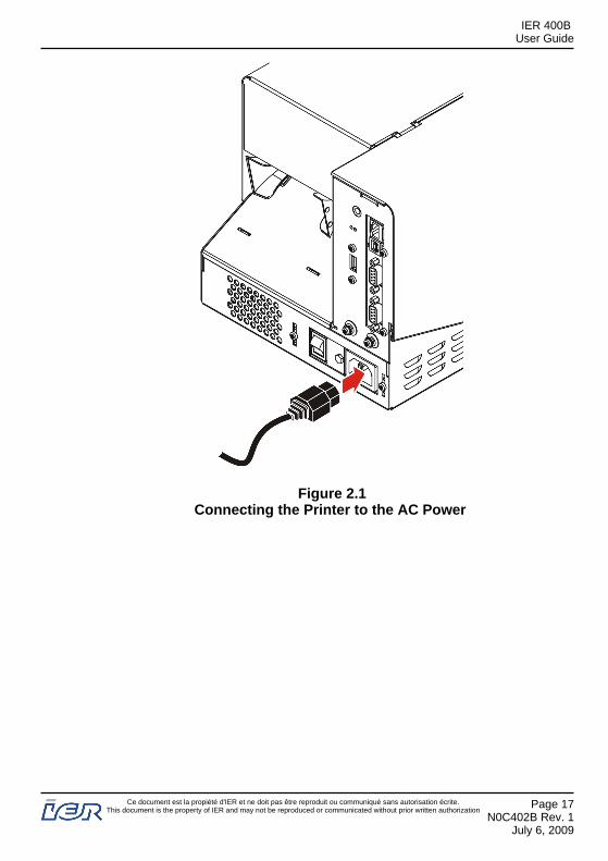
Figure 2.1Connecting the Printer to the AC Power
IER 400BUser Guide
Ce document est la propiété d'IER et ne doit pas être reproduit ou communiqué sans autorisation écrite.This document is the property of IER and may not be reproduced or communicated without prior written authorization
Page 17N0C402B Rev. 1
July 6, 2009
2.1.1.2 Connecting the Printer to the Data CommunicationsSystem
CAUTION
To comply with class A FCC regulations it isnecessary to use a data cable provided with a braidedshield.Use a shielded RS232 cable fitted wit metal platedconnector hoods. The cable shield must be liked tothese hoods and cable length must not exceed 15 m(49.2 ft).The length of a USB cable must not exceed 5 m(16.4 ft).
To connect the printer to the host system, use one of theinterface connectors on the rear connector panel:- 10/100 base T network port (1)- USB 2.0 port (2)- RS232 /DB9 serial port (3) (COM1)- RS232 /DB9 serial port (4) (COM2).
Note: In addition, the rear printer connector panel is provided with a USBHost port (5) to connect a USB key or a Blue Tooth adaptor.
IER 400BUser Guide
Page 18N0C402B Rev. 1July 6, 2009
Ce document est la propiété d'IER et ne doit pas être reproduit ou communiqué sans autorisation écrite.This document is the property of IER and may not be reproduced or communicated without prior written authorization
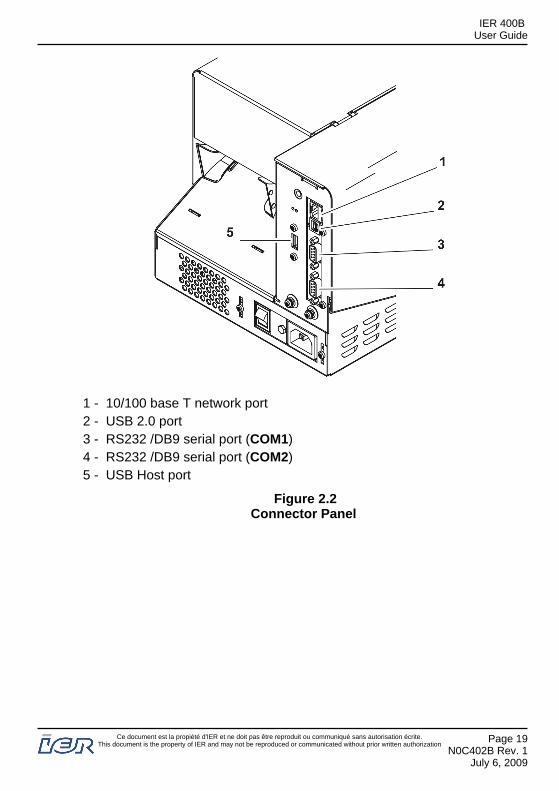
1 - 10/100 base T network port2 - USB 2.0 port3 - RS232 /DB9 serial port (COM1)4 - RS232 /DB9 serial port (COM2)5 - USB Host port
Figure 2.2Connector Panel
IER 400BUser Guide
Ce document est la propiété d'IER et ne doit pas être reproduit ou communiqué sans autorisation écrite.This document is the property of IER and may not be reproduced or communicated without prior written authorization
Page 19N0C402B Rev. 1
July 6, 2009
2.2 POWERING UP THE IER 400 PRINTER
2.2.1 Procedure
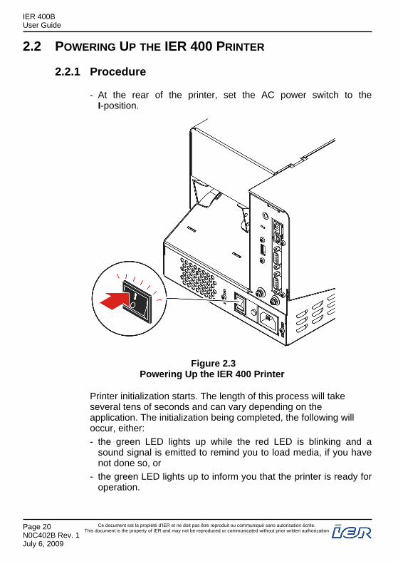
- At the rear of the printer, set the AC power switch to theI-position.
Figure 2.3Powering Up the IER 400 Printer
Printer initialization starts. The length of this process will takeseveral tens of seconds and can vary depending on theapplication. The initialization being completed, the following willoccur, either:- the green LED lights up while the red LED is blinking and a
sound signal is emitted to remind you to load media, if you havenot done so, or
- the green LED lights up to inform you that the printer is ready foroperation.
IER 400BUser Guide
Page 20N0C402B Rev. 1July 6, 2009
Ce document est la propiété d'IER et ne doit pas être reproduit ou communiqué sans autorisation écrite.This document is the property of IER and may not be reproduced or communicated without prior written authorization
2.3 POWERING DOWN THE IER 400 PRINTER
2.3.1 Procedure
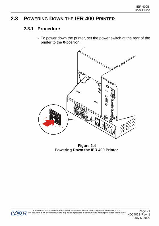
- To power down the printer, set the power switch at the rear of theprinter to the 0-position.
Figure 2.4Powering Down the IER 400 Printer
IER 400BUser Guide
Ce document est la propiété d'IER et ne doit pas être reproduit ou communiqué sans autorisation écrite.This document is the property of IER and may not be reproduced or communicated without prior written authorization
Page 21N0C402B Rev. 1
July 6, 2009
3 INSTALLING AND LOADING THE CONSUMABLES
3.1 OPENING THE PRINTER COVER
3.1.1 Preliminary Information
CAUTION
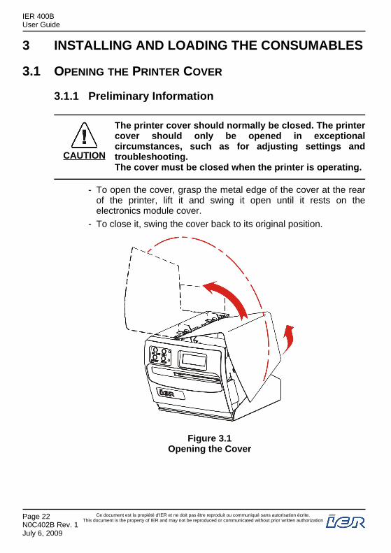
The printer cover should normally be closed. The printercover should only be opened in exceptionalcircumstances, such as for adjusting settings andtroubleshooting.The cover must be closed when the printer is operating.
- To open the cover, grasp the metal edge of the cover at the rearof the printer, lift it and swing it open until it rests on theelectronics module cover.
- To close it, swing the cover back to its original position.
Figure 3.1Opening the Cover
IER 400BUser Guide
Page 22N0C402B Rev. 1July 6, 2009
Ce document est la propiété d'IER et ne doit pas être reproduit ou communiqué sans autorisation écrite.This document is the property of IER and may not be reproduced or communicated without prior written authorization

3.2 INSTALLING FANFOLD MEDIA
3.2.1 Procedure
- Position a box of blank documents at the rear of the printer,following the instructions below.
IMPORTANT: Place the box:- parallel to the printer- in the axis that documents are introduced,- with the heat-sensitive side of the media facing up.
1 - Printer2 - Box of fanfold media3 - Paper intake
Figure 3.2Positioning a Box of Fanfold Media
IER 400BUser Guide
Ce document est la propiété d'IER et ne doit pas être reproduit ou communiqué sans autorisation écrite.This document is the property of IER and may not be reproduced or communicated without prior written authorization
Page 23N0C402B Rev. 1
July 6, 2009
3.3 INSTALLING ROLL MEDIA
3.3.1 Installing a Roll of Documents
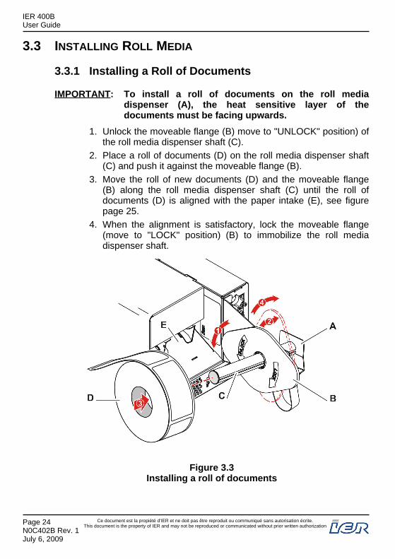
IMPORTANT: To install a roll of documents on the roll mediadispenser (A), the heat sensitive layer of thedocuments must be facing upwards.
1. Unlock the moveable flange (B) move to "UNLOCK" position) ofthe roll media dispenser shaft (C).
2. Place a roll of documents (D) on the roll media dispenser shaft(C) and push it against the moveable flange (B).
3. Move the roll of new documents (D) and the moveable flange(B) along the roll media dispenser shaft (C) until the roll ofdocuments (D) is aligned with the paper intake (E), see figurepage 25.
4. When the alignment is satisfactory, lock the moveable flange(move to "LOCK" position) (B) to immobilize the roll mediadispenser shaft.
Figure 3.3Installing a roll of documents
IER 400BUser Guide
Page 24N0C402B Rev. 1July 6, 2009
Ce document est la propiété d'IER et ne doit pas être reproduit ou communiqué sans autorisation écrite.This document is the property of IER and may not be reproduced or communicated without prior written authorization
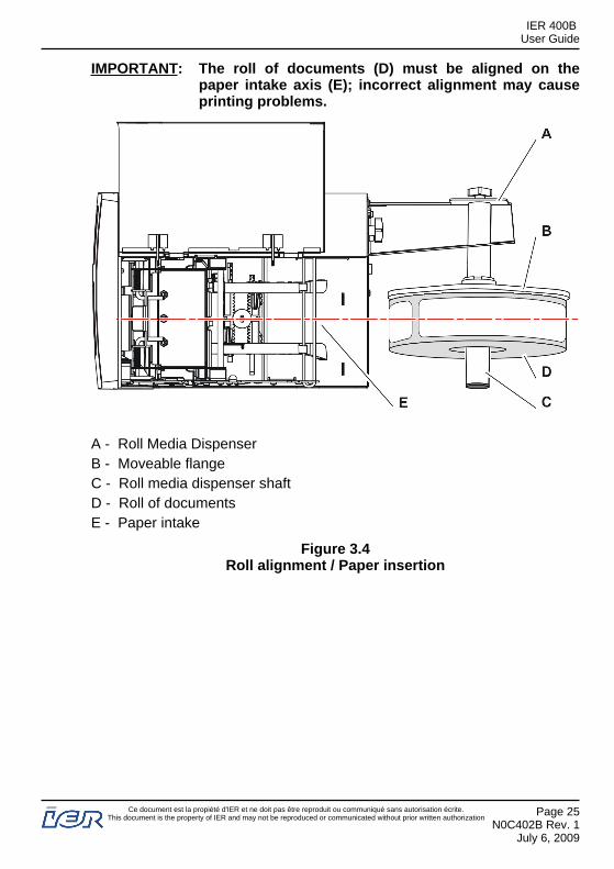
IMPORTANT: The roll of documents (D) must be aligned on thepaper intake axis (E); incorrect alignment may causeprinting problems.
A - Roll Media DispenserB - Moveable flangeC - Roll media dispenser shaftD - Roll of documentsE - Paper intake
Figure 3.4Roll alignment / Paper insertion
IER 400BUser Guide
Ce document est la propiété d'IER et ne doit pas être reproduit ou communiqué sans autorisation écrite.This document is the property of IER and may not be reproduced or communicated without prior written authorization
Page 25N0C402B Rev. 1
July 6, 2009
3.4 ADJUSTING THE PAPER PATH WIDTH
Preliminary Steps: - Make sure the media is correctly loaded. Refer thecorresponding section of the present User Guide.
- Switch the printer off.
3.4.1 Procedure
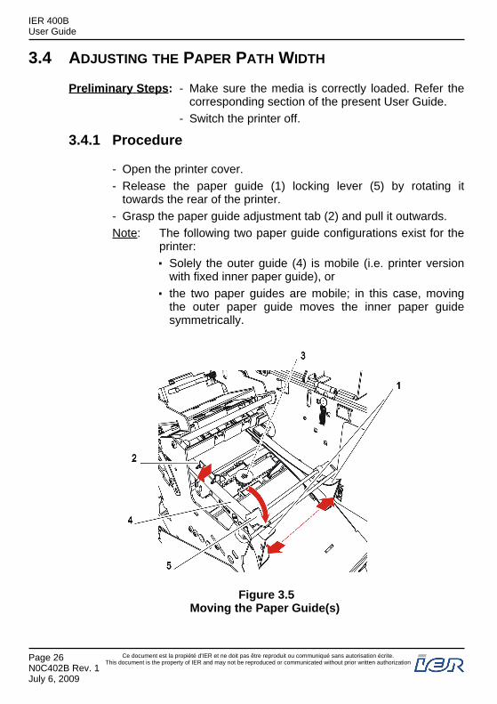
- Open the printer cover.- Release the paper guide (1) locking lever (5) by rotating it
towards the rear of the printer.- Grasp the paper guide adjustment tab (2) and pull it outwards.Note: The following two paper guide configurations exist for the
printer:Solely the outer guide (4) is mobile (i.e. printer versionwith fixed inner paper guide), orthe two paper guides are mobile; in this case, movingthe outer paper guide moves the inner paper guidesymmetrically.
Figure 3.5Moving the Paper Guide(s)
IER 400BUser Guide
Page 26N0C402B Rev. 1July 6, 2009
Ce document est la propiété d'IER et ne doit pas être reproduit ou communiqué sans autorisation écrite.This document is the property of IER and may not be reproduced or communicated without prior written authorization
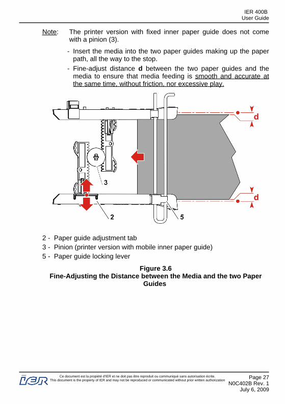
Note: The printer version with fixed inner paper guide does not comewith a pinion (3).
- Insert the media into the two paper guides making up the paperpath, all the way to the stop.
- Fine-adjust distance d between the two paper guides and themedia to ensure that media feeding is smooth and accurate atthe same time, without friction, nor excessive play.
2 - Paper guide adjustment tab3 - Pinion (printer version with mobile inner paper guide)5 - Paper guide locking lever
Figure 3.6Fine-Adjusting the Distance between the Media and the two Paper
Guides
IER 400BUser Guide
Ce document est la propiété d'IER et ne doit pas être reproduit ou communiqué sans autorisation écrite.This document is the property of IER and may not be reproduced or communicated without prior written authorization
Page 27N0C402B Rev. 1
July 6, 2009
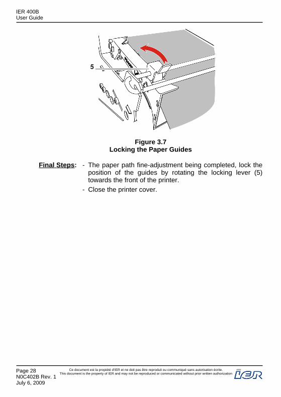
Figure 3.7Locking the Paper Guides
Final Steps: - The paper path fine-adjustment being completed, lock theposition of the guides by rotating the locking lever (5)towards the front of the printer.
- Close the printer cover.
IER 400BUser Guide
Page 28N0C402B Rev. 1July 6, 2009
Ce document est la propiété d'IER et ne doit pas être reproduit ou communiqué sans autorisation écrite.This document is the property of IER and may not be reproduced or communicated without prior written authorization
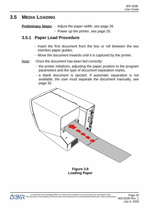
3.5 MEDIA LOADING
Preliminary Steps: - Adjust the paper width, see page 26- Power up the printer, see page 20.
3.5.1 Paper Load Procedure
- Insert the first document from the box or roll between the twoinsertion paper guides.
- Move the document inwards until it is captured by the printer.
Note: Once the document has been fed correctly:- the printer initializes, adjusting the paper position to the program
parameters and the type of document separation marks,- a blank document is ejected. If automatic separation is not
available, the user must separate the document manually, seepage 32.
Figure 3.8Loading Paper
IER 400BUser Guide
Ce document est la propiété d'IER et ne doit pas être reproduit ou communiqué sans autorisation écrite.This document is the property of IER and may not be reproduced or communicated without prior written authorization
Page 29N0C402B Rev. 1
July 6, 2009
4 PRINTER OPERATION
4.1 INDICATOR AND KEY FUNCTIONS
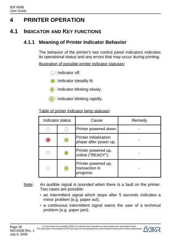
4.1.1 Meaning of Printer Indicator Behavior
The behavior of the printer's two control panel indicators indicatesits operational status and any errors that may occur during printing.
Illustration of possible printer indicator statuses:
: Indicator off.
: Indicator steadily lit.
: Indicator blinking slowly.
: Indicator blinking rapidly.
Table of printer indicator lamp statuses:
Indicator status Cause Remedy
Printer powered down. -
Printer initializationphase after power up. -
Printer powered up,online ("READY"). -
Printer powered up,transaction inprogress.
-
Note: An audible signal is sounded when there is a fault on the printer.Two cases are possible:
an intermittent signal which stops after 5 seconds indicates aminor problem (e.g. paper out),a continuous intermittent signal warns the user of a technicalproblem (e.g. paper jam).
IER 400BUser Guide
Page 30N0C402B Rev. 1July 6, 2009
Ce document est la propiété d'IER et ne doit pas être reproduit ou communiqué sans autorisation écrite.This document is the property of IER and may not be reproduced or communicated without prior written authorization
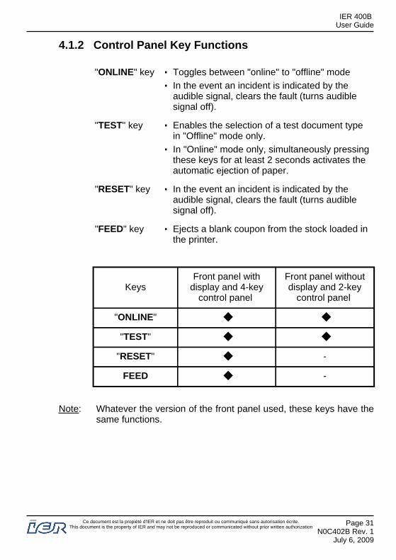
4.1.2 Control Panel Key Functions
"ONLINE" key Toggles between "online" to "offline" modeIn the event an incident is indicated by theaudible signal, clears the fault (turns audiblesignal off).
"TEST" key Enables the selection of a test document typein "Offline" mode only.In "Online" mode only, simultaneously pressingthese keys for at least 2 seconds activates theautomatic ejection of paper.
"RESET" key In the event an incident is indicated by theaudible signal, clears the fault (turns audiblesignal off).
"FEED" key Ejects a blank coupon from the stock loaded inthe printer.
KeysFront panel with
display and 4-keycontrol panel
Front panel withoutdisplay and 2-key
control panel
"ONLINE" ◆ ◆
"TEST" ◆ ◆
"RESET" ◆ -
FEED ◆ -
Note: Whatever the version of the front panel used, these keys have thesame functions.
IER 400BUser Guide
Ce document est la propiété d'IER et ne doit pas être reproduit ou communiqué sans autorisation écrite.This document is the property of IER and may not be reproduced or communicated without prior written authorization
Page 31N0C402B Rev. 1
July 6, 2009

4.2 PRINTING DOCUMENTS
Preliminary Steps: Before using the printer, perform the following checks:- Printer is connected to the power supply and the
host data communications system, see page 15.- Printer is powered up, see page 20.- Printer is loaded with media, see page 29.- If necessary, refer to the section describing printer
functions, see page 30
4.2.1 Document printing procedure
- Set the printer to "Online" by pressing the "ONLINE" key.- Launch a print command from the host system.
The green indicator blinks during printing.
When printing is finished, if the printer is equipped with the cutterassembly, the document is automatically cut and presented to theuser.
If the printer is not equipped with the optional cutting assembly toautomatically separate documents, use the serrated edges of theoutput slot on the front of the printer to manually separate theprinted document, tearing it up or down sharply.
IER 400BUser Guide
Page 32N0C402B Rev. 1July 6, 2009
Ce document est la propiété d'IER et ne doit pas être reproduit ou communiqué sans autorisation écrite.This document is the property of IER and may not be reproduced or communicated without prior written authorization

Figure 4.1Separating documents by tearing off
IER 400BUser Guide
Ce document est la propiété d'IER et ne doit pas être reproduit ou communiqué sans autorisation écrite.This document is the property of IER and may not be reproduced or communicated without prior written authorization
Page 33N0C402B Rev. 1
July 6, 2009

5 USER LEVEL TROUBLESHOOTING
5.1 OPERATING FAULTS
In most cases, a printer operating fault activates the indicators and anaudible signal.
Note: An intermittent signal stopping after 5 seconds indicates a minorproblem, but a continuous signal indicates a technical problem.
5.1.1 When powering up, the printer does not start up
Note: If necessary, remove the media from the printer to access the rearof the printer, see page 42.
- Power down the printer (set power switch to "0" position).- Check the presence of the AC power supply with another
electrical device.- Check the connections of the power cable to the printer
connector and to the power supply.- Restart the printer (set power switch to "I" position).- Wait for the printer to initialize then ensure that the green
indicator lamp is lit in "Online" mode.
If after all these steps the printer does not start up, call the helpdesk.
5.1.2 The printer does not receive print data
Note: If necessary, remove the media from the printer to access to therear of the printer, see page 42.
- Power down the printer (set power switch to "0" position).- Check the connections of the data cable to the printer connector
and to the computer system (computer, network, hub, etc.).- Restart the printer (set power switch to "I" position) and check
that the green indicator lamp is lit in "Online" mode.
Note: If you removed paper media from the printer beforehand, reload itsee page 29.
IER 400BUser Guide
Page 34N0C402B Rev. 1July 6, 2009
Ce document est la propiété d'IER et ne doit pas être reproduit ou communiqué sans autorisation écrite.This document is the property of IER and may not be reproduced or communicated without prior written authorization
- Send a print command from the host system; the printer shouldexecute the requested task.
If the above actions do not solve the problem, call the help desk.
5.1.3 The paper is not feeding
- Check that the printhead assembly is correctly locked,see page 40.
- Insert blank media, all the way, between the paper guides untilpositioned under the printhead assembly.
- Ensure that there is no paper chaff in the paper path that couldinterfere with media feeding.
If the above actions do not solve the problem, call the help desk.
5.1.4 Poor print quality
This problem may have several causes:dirty printing mechanismprint parameter settings do not correspond to the type of mediaused,printhead assembly incorrectly locked, see page 40.faulty part(s).
If the print quality is not satisfactory despite the checks performed,call the help desk.
IER 400BUser Guide
Ce document est la propiété d'IER et ne doit pas être reproduit ou communiqué sans autorisation écrite.This document is the property of IER and may not be reproduced or communicated without prior written authorization
Page 35N0C402B Rev. 1
July 6, 2009
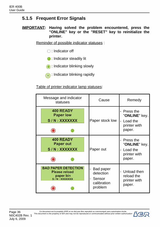
5.1.5 Frequent Error Signals
IMPORTANT: Having solved the problem encountered, press the"ONLINE" key or the "RESET" key to reinitialize theprinter.
Reminder of possible indicator statuses :
: Indicator off
: Indicator steadily lit
: Indicator blinking slowly
: Indicator blinking rapidly
Table of printer indicator lamp statuses:
Message and indicatorstatuses Cause Remedy
Paper stock low
- Press the"ONLINE" key.
- Load theprinter withpaper.
Paper out
- Press the"ONLINE" key.
- Load theprinter withpaper.
- Bad paperdetection
- Sensorcalibrationproblem
- Unload thenreload theprinter withpaper.
IER 400BUser Guide
Page 36N0C402B Rev. 1July 6, 2009
Ce document est la propiété d'IER et ne doit pas être reproduit ou communiqué sans autorisation écrite.This document is the property of IER and may not be reproduced or communicated without prior written authorization
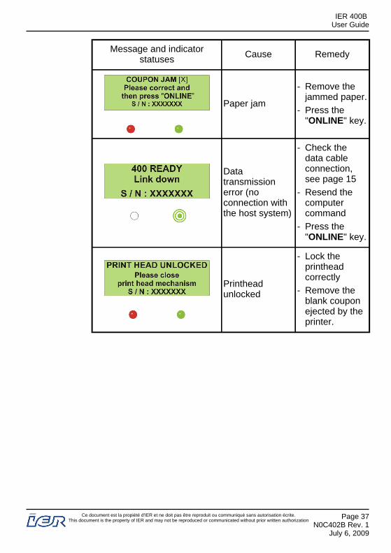
Message and indicatorstatuses Cause Remedy
Paper jam
- Remove thejammed paper.
- Press the"ONLINE" key.
Datatransmissionerror (noconnection withthe host system)
- Check thedata cableconnection,see page 15
- Resend thecomputercommand
- Press the"ONLINE" key.
Printheadunlocked
- Lock theprintheadcorrectly
- Remove theblank couponejected by theprinter.
IER 400BUser Guide
Ce document est la propiété d'IER et ne doit pas être reproduit ou communiqué sans autorisation écrite.This document is the property of IER and may not be reproduced or communicated without prior written authorization
Page 37N0C402B Rev. 1
July 6, 2009
5.2 OPENING THE PRINTHEAD ASSEMBLY - CLEARING ADOCUMENT JAM
WARNING
Before performing any service operation on the printer:unload the paper from the printer, see page 42switch off the printer,disconnect the printer from the power supply,disconnect the data cable.
CAUTION
The printhead is a sensitive electronic component,therefore it is essential to:- put on an anti-static wrist strap before touching it,- avoid any shocks to the printhead,- do not use any tools that could damage it,- do not touch the line of heating elements.
IMPORTANT: Make sure the printhead assembly is closed / lockedduring normal printing operations.
Note: Open the printhead assembly only when necessary, for examplewhen you need access to the paper path to clear a paper jam or toservice the printer.
Preliminary Steps: - Open the printer cover.
5.2.1 Procedure
- Grasp the two levers (1) with your thumb and forefinger andpress them together to unlock the printhead support (2).
- Rotate the printhead support (2) towards the rear, all the way tothe stop.
- Grasp the front edge of the printhead (3) and rotate the printhead(3) to the rear.
Note: Opening the printhead allows you to remove a document(4) stuck in the printhead area, which is causing a jam inthe front part of the printer.
IER 400BUser Guide
Page 38N0C402B Rev. 1July 6, 2009
Ce document est la propiété d'IER et ne doit pas être reproduit ou communiqué sans autorisation écrite.This document is the property of IER and may not be reproduced or communicated without prior written authorization
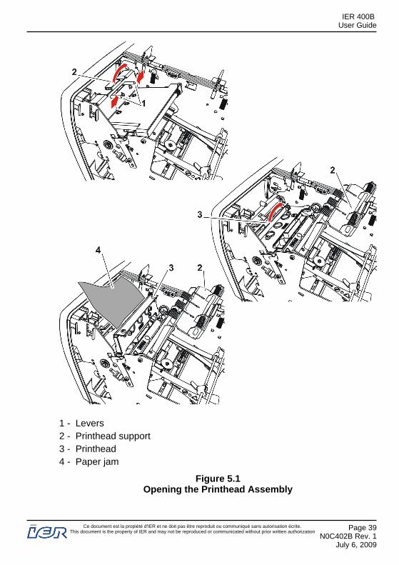
1 - Levers2 - Printhead support3 - Printhead4 - Paper jam
Figure 5.1Opening the Printhead Assembly
IER 400BUser Guide
Ce document est la propiété d'IER et ne doit pas être reproduit ou communiqué sans autorisation écrite.This document is the property of IER and may not be reproduced or communicated without prior written authorization
Page 39N0C402B Rev. 1
July 6, 2009

5.3 CLOSING AND LOCKING THE PRINTHEAD ASSEMBLY
5.3.1 Procedure
CAUTION
Before reinstalling the printhead, make sure the rotatingpins on each side of the printhead (3) are correctlypositioned in their respective seats on the printer.
- Rotate the printhead (3) toward the front of the printer.- Rotate the printhead support (2) toward the front of the printer,
onto the printhead (3).- Press firmly on the green tab at the front of the printhead support
(2) until the assembly clicks into the locked position.
CAUTION
When locking the printhead support (2), make sure youclearly hear two clicks indicating that the two levers (1)have snapped back into position in their respectiveseats.Ensure that the printhead support (2) is solidly locked inposition.
- If no other service operation is to be performed on the printer :close the printer cover,
reconnect the data cable,
reconnect the power cord,
power up the printer
and load the printer with paper.
IER 400BUser Guide
Page 40N0C402B Rev. 1July 6, 2009
Ce document est la propiété d'IER et ne doit pas être reproduit ou communiqué sans autorisation écrite.This document is the property of IER and may not be reproduced or communicated without prior written authorization
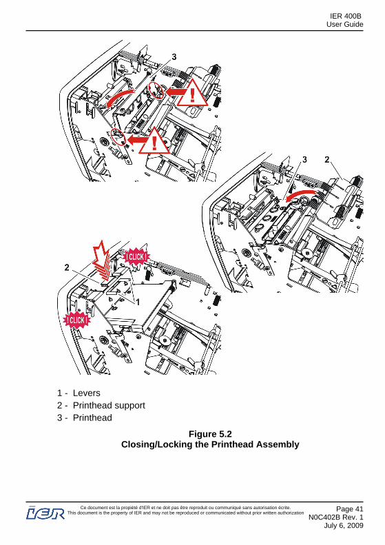
1 - Levers2 - Printhead support3 - Printhead
Figure 5.2Closing/Locking the Printhead Assembly
IER 400BUser Guide
Ce document est la propiété d'IER et ne doit pas être reproduit ou communiqué sans autorisation écrite.This document is the property of IER and may not be reproduced or communicated without prior written authorization
Page 41N0C402B Rev. 1
July 6, 2009
5.4 UNLOADING THE MEDIA
5.4.1 Automatic Removal
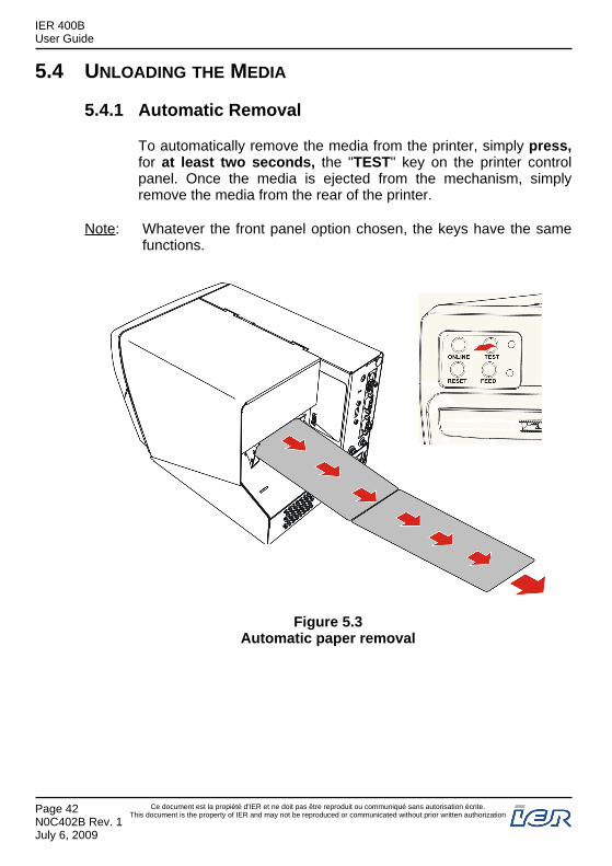
To automatically remove the media from the printer, simply press,for at least two seconds, the "TEST" key on the printer controlpanel. Once the media is ejected from the mechanism, simplyremove the media from the rear of the printer.
Note: Whatever the front panel option chosen, the keys have the samefunctions.
Figure 5.3Automatic paper removal
IER 400BUser Guide
Page 42N0C402B Rev. 1July 6, 2009
Ce document est la propiété d'IER et ne doit pas être reproduit ou communiqué sans autorisation écrite.This document is the property of IER and may not be reproduced or communicated without prior written authorization
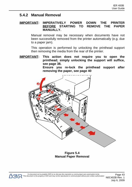
5.4.2 Manual Removal
IMPORTANT: IMPERATIVELY POWER DOWN THE PRINTERBEFORE STARTING TO REMOVE THE PAPERMANUALLY.
Manual removal may be necessary when documents have notbeen successfully removed from the printer automatically (e.g. dueto a paper jam).
This operation is performed by unlocking the printhead supportthen removing the media from the rear of the printer.
IMPORTANT: This action does not require you to open theprinthead; simply unlocking the support will suffice,see page 38.Ensure you re-lock the printhead support afterremoving the paper, see page 40
Figure 5.4Manual Paper Removal
IER 400BUser Guide
Ce document est la propiété d'IER et ne doit pas être reproduit ou communiqué sans autorisation écrite.This document is the property of IER and may not be reproduced or communicated without prior written authorization
Page 43N0C402B Rev. 1
July 6, 2009

IER 400BUser Guide
Page 44N0C402B Rev. 1July 6, 2009
Ce document est la propiété d'IER et ne doit pas être reproduit ou communiqué sans autorisation écrite.This document is the property of IER and may not be reproduced or communicated without prior written authorization
6 PRINTER MAINTENANCE
6.1 RECOMMENDED PERIODIC MAINTENANCE
Schedule: Every 2 weeks or after 2000 m of printing.
Estimated Time: 15 min.
Tools Required / Maintenance Products: - IER cleaning kit, ref. S32129A
WARNING
Before starting to clean the printer:- unload the paper from the printer, see page 42- switch off the printer,- disconnect the printer from the power supply,- disconnect the data cable.
6.1.1 Periodic maintenance frequency
To ensure optimum use of the printer under normal conditions, IERrecommends periodic cleaning every 2 weeks or after 2000m ofprinting.
IMPORTANT: The frequency of cleaning must be adapted to thespecific environmental and operating conditions of theprinter (dusty atmosphere, paper quality, sustainedprinter use, etc. ).
Use the IER cleaning kit, ref. S32129A following the instructions inthe kit, and applying the procedures described in this document.
CAUTION
IER declines all liability for incidents arising from failureto follow its recommendations regarding serviceintervals, products and procedures.
IER 400BUser Guide
Ce document est la propiété d'IER et ne doit pas être reproduit ou communiqué sans autorisation écrite.This document is the property of IER and may not be reproduced or communicated without prior written authorization
Page 45N0C402B Rev. 1
July 6, 2009
6.2 PERIODIC MAINTENANCE PROCEDURES
6.2.1 Removing Dust From the Printer Mechanism
WARNING
To carry out this operation, IER recommends that youonly use the can of compressed air supplied with thecleaning kit, since it has been tested and approved asnon-flammable and non-explosive.IER will not accept responsibility for problems arisingfrom the use of any other product.DO NOT USE THE DUSTER CAN IF THERE IS VERYLITTLE AIR LEFT. THE CAN MOSTLY CONTAINSPROPELLENT, WHICH IS HIGHLY FLAMMABLE.
Use the duster can supplied with the IER Cleaning Kit, followingthe safety precautions on the can and those mentioned above,dislodge any paper chaff and dust in the printer by blowing air intothe following zones:
Arrow #5: inside the two paper guides,Arrow #4: under the two paper guides and the print mechanism,Arrow #3: at the end of the paper path around the media sensorArrows #2: on the platen, to the document separation marksensors and behind the printer front panel, where the optionalcutter is installed,Arrows # 1: in the output slot in the front panel.
IER 400BUser Guide
Page 46N0C402B Rev. 1July 6, 2009
Ce document est la propiété d'IER et ne doit pas être reproduit ou communiqué sans autorisation écrite.This document is the property of IER and may not be reproduced or communicated without prior written authorization
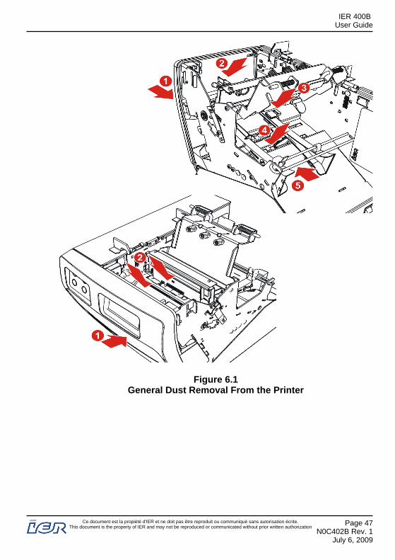
Figure 6.1General Dust Removal From the Printer
IER 400BUser Guide
Ce document est la propiété d'IER et ne doit pas être reproduit ou communiqué sans autorisation écrite.This document is the property of IER and may not be reproduced or communicated without prior written authorization
Page 47N0C402B Rev. 1
July 6, 2009

6.2.2 Cleaning the Printhead and Platen
CAUTION
The printhead is a sensitive electronic component:- put on an anti-static wrist strap before touching it,- avoid physical shocks to the printhead,- do not use any tools that could damage it,- do not touch the printhead heating elements.
Proceed as follows, using the products in the IER cleaning kit and followingthe enclosed instructions:- Use one of the soft, lint-free cloths and moisten it slightly with the
recommended cleaning product to clean the platen surface (2); rotate theplaten (2) manually to have access to the entire platen surface (2).
- Using alcohol filled foam swabs, clean the whole surface of the printheadheating elements (1).
IER 400BUser Guide
Page 48N0C402B Rev. 1July 6, 2009
Ce document est la propiété d'IER et ne doit pas être reproduit ou communiqué sans autorisation écrite.This document is the property of IER and may not be reproduced or communicated without prior written authorization

1 - Printhead2 - Platen
Figure 6.2Cleaning the Printhead and Platen
IER 400BUser Guide
Ce document est la propiété d'IER et ne doit pas être reproduit ou communiqué sans autorisation écrite.This document is the property of IER and may not be reproduced or communicated without prior written authorization
Page 49N0C402B Rev. 1
July 6, 2009

6.3 RESTORING THE PRINTER TO OPERATIONAL CONDITIONFOLLOWING PERIODIC MAINTENANCE
6.3.1 Actions to be Performed Before Putting the PrinterInto Service
After performing periodic maintenance operations:- Close / Lock the printhead assembly, see page 40.- Close the printer cover.- Connect the data cable and the power cord, see page 15.- Switch the printer on, see page 20.- Load paper into the printer, see page 29.- Print a document to check the print quality, see page 32.
IER 400BUser Guide
Page 50N0C402B Rev. 1July 6, 2009
Ce document est la propiété d'IER et ne doit pas être reproduit ou communiqué sans autorisation écrite.This document is the property of IER and may not be reproduced or communicated without prior written authorization


