1. Make sure you have the anti-theft codes for the radio and the navigation system, then write down the frequencies for the radio's preset buttons.
2. Disconnect the battery negative cable, then disconnect the positive cable, and wait at least 3 minutes.
2004 Acura TSX
2004 ELECTRICAL Fuse/Relay Boxes - TSX
Wednesday, March 12, 2008 12:03:27 AM Page 6
3. Remove the under-hood multi-relay box (Canada) from the under-hood fuse/relay box. 4. Remove the screws (A) from the alternator and battery cable terminals. 5. Remove the two mounting bolts (B) from the under-hood fuse/relay box. 6. Remove the under cover from the under-hood fuse/relay box. 7. Disconnect the connectors from the under-hood fuse/relay box.
2004 Acura TSX
2004 ELECTRICAL Fuse/Relay Boxes - TSX
Wednesday, March 12, 2008 12:03:27 AM Page 7
2004 Acura TSX
2004 ELECTRICAL Fuse/Relay Boxes - TSX
Wednesday, March 12, 2008 12:03:27 AM Page 8
Fig. 11: Removing The Under-Hood Fuse/Relay Box
Installation
1. Connect the connectors to the under-hood fuse/relay box, then install the under-hood fuse/relay box in the reverse order of removal.
2. Install the removed parts in the reverse order of removal. 3. Connect the both positive cable and negative cable to the battery. 4. Do the ECM/PCM idle learn procedure (see ECM/PCM IDLE LEARN PROCEDURE ). 5. Do the power window control unit reset procedure (see RESETTING THE POWER WINDOW ). 6. Enter the anti-theft codes for the radio and navigation system, then enter the customer's radio station
presets. 7. Confirm that all systems work properly.
DTC TROUBLESHOOTING
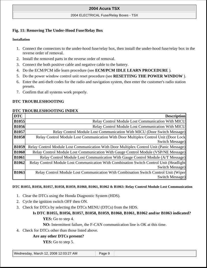
DTC TROUBLESHOOTING INDEX
DTC B1055, B1056, B1057, B1058, B1059, B1060, B1061, B1062 & B1063: Relay Control Module Lost Communication
1. Clear the DTCs using the Honda Diagnostic System (HDS). 2. Cycle the ignition switch OFF then ON. 3. Check for DTCs by selecting the DTCs MENU (DTCs) from the HDS.
Is DTC B1055, B1056, B1057, B1058, B1059, B1060, B1061, B1062 and/or B1063 indicated? YES: Go to step 4. NO: Intermittent failure, the F-CAN communication line is OK at this time.
4. Check for DTCs other than those listed above. Are any other DTCs present?
YES: Go to step 5.
DTC DescriptionB1055 Relay Control Module Lost Communication With MICUB1056 Relay Control Module Lost Communication With MICUB1057 Relay Control Module Lost Communication With MICU (Door Switch Message)B1058 Relay Control Module Lost Communication With Door Multiplex Control Unit (Door Lock
Switch Message)B1059 Relay Control Module Lost Communication With Door Multiplex Control Unit (Panic Message)B1060 Relay Control Module Lost Communication With Gauge Control Module (VSP/NE Message)B1061 Relay Control Module Lost Communication With Gauge Control Module (A/T Message)B1062 Relay Control Module Lost Communication With Combination Switch Control Unit (Headlight
Switch Message)B1063 Relay Control Module Lost Communication With Combination Switch Control Unit (Wiper
Switch Message)
2004 Acura TSX
2004 ELECTRICAL Fuse/Relay Boxes - TSX
Wednesday, March 12, 2008 12:03:27 AM Page 9
NO: Perform Relay Control Module Input Test (see RELAY CONTROL MODULE INPUT TEST ).
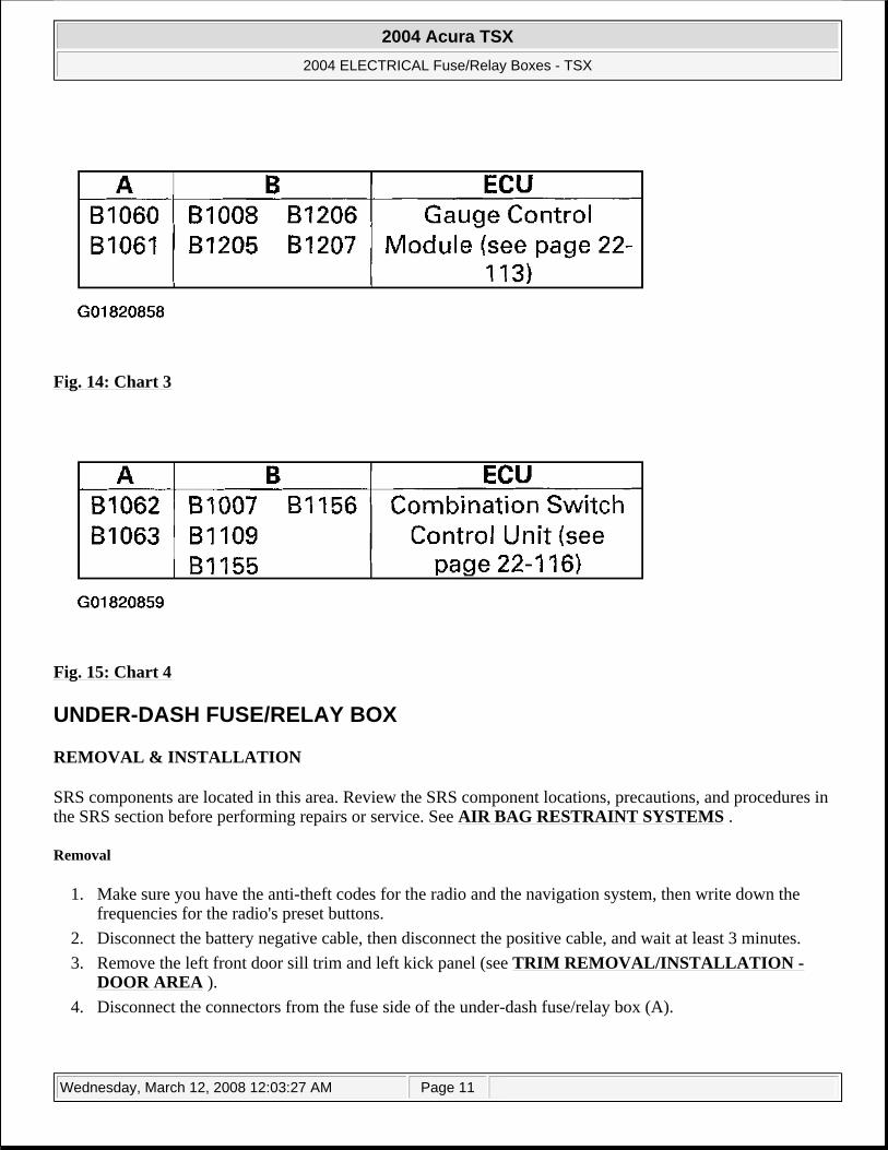
5. Find the chart that contains at least one retrieved DTC in column A and one retrieved DTC in column B. Perform the input test for the ECU listed in that chart. See Fig. 12 through Fig. 15 . If no DTC from column B is found then continue to Relay Control Module input test.
Fig. 12: Chart 1
Fig. 13: Chart 2
2004 Acura TSX
2004 ELECTRICAL Fuse/Relay Boxes - TSX
Wednesday, March 12, 2008 12:03:27 AM Page 10
Fig. 14: Chart 3
Fig. 15: Chart 4
UNDER-DASH FUSE/RELAY BOX
REMOVAL & INSTALLATION
SRS components are located in this area. Review the SRS component locations, precautions, and procedures in the SRS section before performing repairs or service. See AIR BAG RESTRAINT SYSTEMS .
Removal
1. Make sure you have the anti-theft codes for the radio and the navigation system, then write down the frequencies for the radio's preset buttons.
2. Disconnect the battery negative cable, then disconnect the positive cable, and wait at least 3 minutes. 3. Remove the left front door sill trim and left kick panel (see TRIM REMOVAL/INSTALLATION -
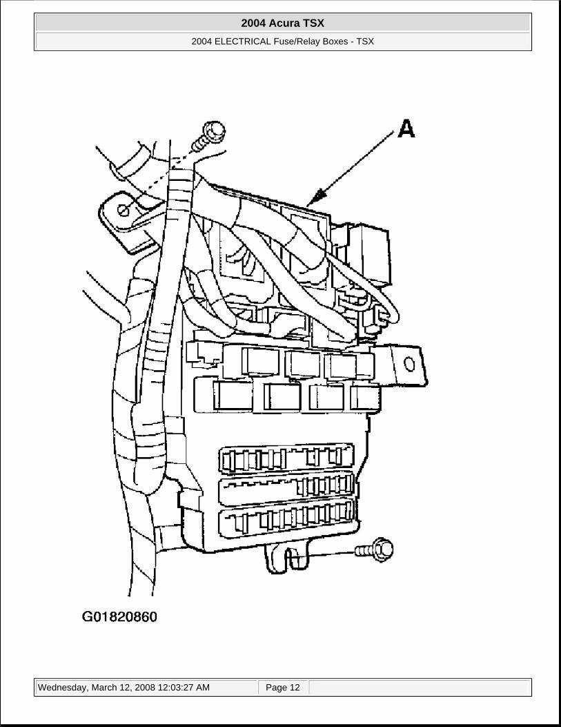
DOOR AREA ). 4. Disconnect the connectors from the fuse side of the under-dash fuse/relay box (A).
2004 Acura TSX
2004 ELECTRICAL Fuse/Relay Boxes - TSX
Wednesday, March 12, 2008 12:03:27 AM Page 11
2004 Acura TSX
2004 ELECTRICAL Fuse/Relay Boxes - TSX
Wednesday, March 12, 2008 12:03:27 AM Page 12
Fig. 16: Disconnecting The Connectors From The Fuse Side Of The Under-Dash Fuse/Relay Box
5. Remove the two mounting bolts and pull the fuse/relay box away from the body. 6. Disconnect the connectors and remove the under-dash fuse/relay box.
Installation
1. Connect the connectors to the under-dash fuse/relay box, then install the under-dash fuse/relay box in the reverse order of removal.
2. Install the removed parts in the reverse order of removal. 3. Connect both the positive cable and negative cable to the battery. 4. Do the ECM/PCM idle learn procedure (see ECM/PCM IDLE LEARN PROCEDURE ). 5. Do the power window control unit reset procedure (see RESETTING THE POWER WINDOW ). 6. Enter the anti-theft codes for the radio and navigation system, then enter the customer's radio station
presents. 7. Confirm that all systems work properly.
RELAYS
POWER RELAY TEST
Use this chart to identify the type of relay, then do the test listed for it. See Fig. 17 .
NOTE: Some SRS harness connectors are spring-loaded lock type (see AIR BAG RESTRAINT SYSTEMS ).
NOTE: For the turn signal/hazard relay input test, see TURN SIGNAL/HAZARD RELAY INPUT TEST ).
2004 Acura TSX
2004 ELECTRICAL Fuse/Relay Boxes - TSX
Wednesday, March 12, 2008 12:03:27 AM Page 13
Fig. 17: Relay Identification Table
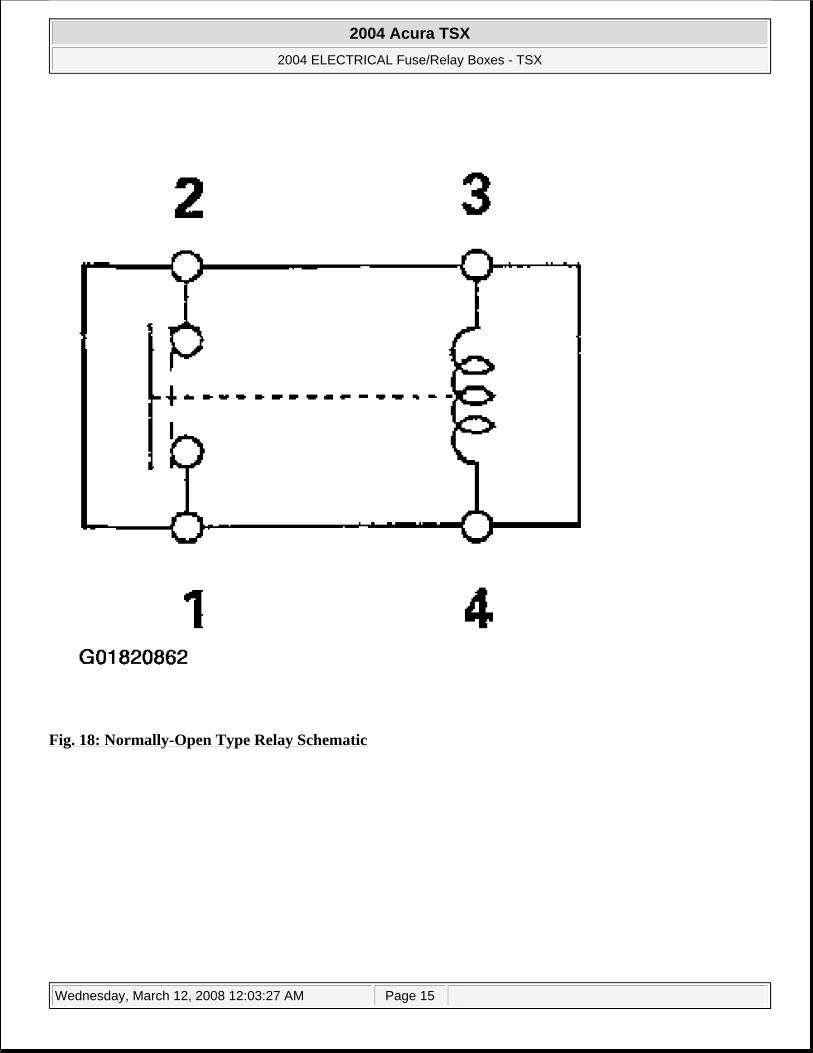
Normally-open type
Check for continuity between the terminals:
There should be continuity between the No. 1 and No. 2 terminals when power and ground are connected to the No. 3 and No. 4 terminals. There should be no continuity between the No. 1 and No. 2 terminals when power is disconnected.
2004 Acura TSX
2004 ELECTRICAL Fuse/Relay Boxes - TSX
Wednesday, March 12, 2008 12:03:27 AM Page 14
Fig. 18: Normally-Open Type Relay Schematic
2004 Acura TSX
2004 ELECTRICAL Fuse/Relay Boxes - TSX
Wednesday, March 12, 2008 12:03:27 AM Page 15
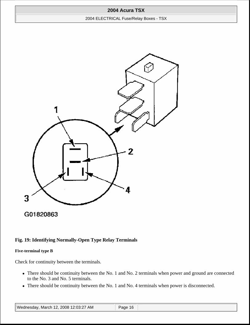
Fig. 19: Identifying Normally-Open Type Relay Terminals
Five-terminal type B
Check for continuity between the terminals.
There should be continuity between the No. 1 and No. 2 terminals when power and ground are connected to the No. 3 and No. 5 terminals. There should be continuity between the No. 1 and No. 4 terminals when power is disconnected.
2004 Acura TSX
2004 ELECTRICAL Fuse/Relay Boxes - TSX
Wednesday, March 12, 2008 12:03:27 AM Page 16
Fig. 20: Five-Terminal Type B Relay Schematic
2004 Acura TSX
2004 ELECTRICAL Fuse/Relay Boxes - TSX
Wednesday, March 12, 2008 12:03:27 AM Page 17
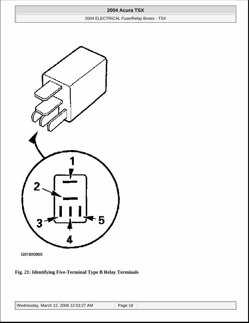
Fig. 21: Identifying Five-Terminal Type B Relay Terminals