XtremeAir GmbH, Harzstr.2, D-39444 Hecklingen Document No. SB-2013-003 Tel: +49 39267 60999 0, Fax: +49 39267 60999 20 www.xtremeair.de [email protected]Issue: A.02 DOA-Nr.: EASA.21J.360 Service Bulletin SB-2013-003 Date: 26.11.2013 Replaces Service Bulletin No. / Date: SB-2013-003 A.01 25.03.2013 Page 1 / 13 Priority 3 – Product improvement Subject: Master Brake Cylinder Aircraft type affected: XA41 & XA42 Serial numbers affected: MSN 01 through 06 and MSN 101 through 120 Compliance: Optional Time of Compliance: at operator’s discretion Purpose: To notify owners of above aircraft of the availability of an improved brake cylinder assembly, and to provide instructions for the removal of the Master Cylinder XA42-3280-230 and the installation of the Master Cylinder 694-3 XA42-3280-232 and Reservoir assembly XA42-3280-233. Background: The previous master brake cylinder XA42-3280-230 might show some leakage of brake fluid, particularly during inverted flight. Manpower: It is estimated that approximately three (3) man-hours will be required to accomplish this bulletin. For the single seat XA41 aircraft, pedal carts need to be sent to XtremeAir for modification. Materials: The following parts kit should be ordered through [email protected]: (2) ea. Master Cylinder 694-3 XA42-3280-232 (2) ea. Reservoir Assembly XA42-3280-233 (4) ea. Reservoir Fitting XA42-3280-250 (2) ea. Reservoir Fitting reduction XA42-3280-249 (2) ea. Blue brake hose l=150mm (4) ea. Lens head screws AN 526-8 R 6 (4) ea. Washer AN 960-8 (4) ea. Hexagonal stop nut MS 21083 N 08 (4) ea. Tap washer 6.4 DIN 463 (6) ea. Split pin 2 x 12 Additionally for XA41: (1) ea. Adjustment cart LH & RH XA41-2780-111 and -116 (2) ea. 90° Elbow fitting AN 822-3D (2) ea. Stop nut MS21083N3
DOA-Nr.: EASA.21J.360 Service Bulletin SB-2013-003 Date: 26.11.2013
Replaces Service Bulletin No. / Date: SB-2013-003 A.01 25.03.2013
Page 1 / 13
Priority 3 – Product improvement
Subject: Master Brake Cylinder Aircraft type affected: XA41 & XA42 Serial numbers affected: MSN 01 through 06 and MSN 101 through 120 Compliance: Optional Time of Compliance: at operator’s discretion Purpose: To notify owners of above aircraft of the availability of an improved
brake cylinder assembly, and to provide instructions for the removal of the Master Cylinder XA42-3280-230 and the installation of the Master Cylinder 694-3 XA42-3280-232 and Reservoir assembly XA42-3280-233.
Background: The previous master brake cylinder XA42-3280-230 might show
some leakage of brake fluid, particularly during inverted flight. Manpower: It is estimated that approximately three (3) man-hours will be
required to accomplish this bulletin. For the single seat XA41 aircraft, pedal carts need to be sent to
XtremeAir for modification. Materials: The following parts kit should be ordered through
[email protected]: (2) ea. Master Cylinder 694-3 XA42-3280-232 (2) ea. Reservoir Assembly XA42-3280-233 (4) ea. Reservoir Fitting XA42-3280-250 (2) ea. Reservoir Fitting reduction XA42-3280-249 (2) ea. Blue brake hose l=150mm (4) ea. Lens head screws AN 526-8 R 6 (4) ea. Washer AN 960-8 (4) ea. Hexagonal stop nut MS 21083 N 08 (4) ea. Tap washer 6.4 DIN 463 (6) ea. Split pin 2 x 12 Additionally for XA41: (1) ea. Adjustment cart LH & RH XA41-2780-111 and -116 (2) ea. 90° Elbow fitting AN 822-3D (2) ea. Stop nut MS21083N3
DOA-Nr.: EASA.21J.360 Service Bulletin SB-2013-003 Date: 26.11.2013
Replaces Service Bulletin No. / Date: SB-2013-003 A.01 25.03.2013
Page 2 / 13
Additionally for XA42: (1) ea. Reservoir Holder LH XA42-3280-251 (1) ea. Reservoir Holder RH XA42-3280-252 (2) ea. 45° Elbow fitting AN 823-3D The following consumables are required:
Locking varnish
Mil-H-5606 red hydraulic fluid Accomplishment Instructions: Perform the following for both, left and right hand pedals. Important: When brake fluid is spilled, clean immediately to avoid
paint damage. Avoid contact between brake fluid and skin. For XA42 Disassembly and assembly
1. Disconnect the brake line from the master brake cylinder and collect the brake fluid.
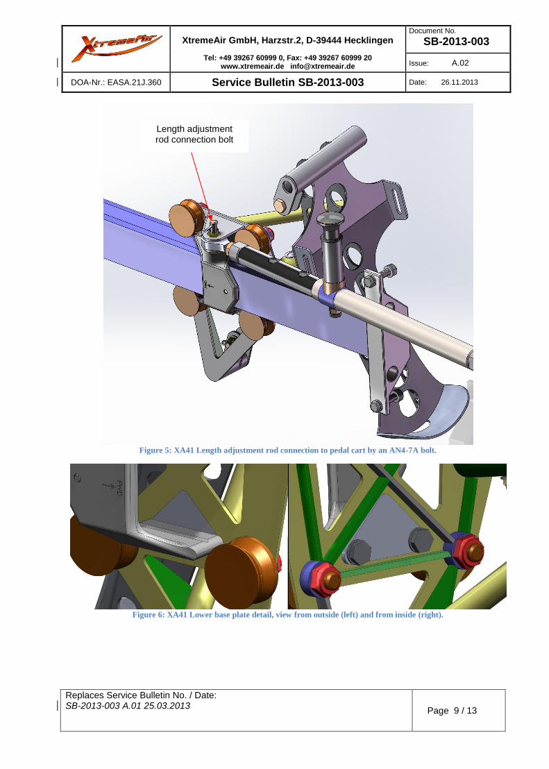
2. Disconnect the connection from the length adjustment rod by removing the AN4-7A bolt. Make sure the split pin is removed before loosening the nut.
3. Remove the two (2) M6x20 bolts from the rear pedal rail mount. Make sure to unfold the tap washer before removing the bolts.
4. Remove the pedal and rail. 5. Remove the master brake cylinder from the pedal by removing
the two (2) AN4-7A bolts. Make sure the split pin is removed before loosening the nuts.
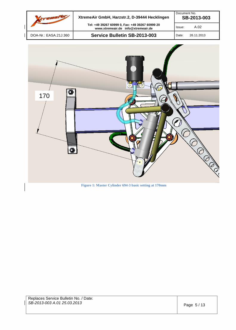
6. Set the basic Master Cylinder 694-3 length to 170mm. (See Figure 1).
7. Assemble the master cylinder making sure the fitting connections face forward. Use a new split pin to secure the bolts.
8. Insert the pedal back in the rail. 9. Assemble pedal and rail by screwing the rail mount back on
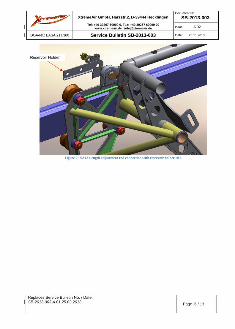
the fuselage wall. Use a new tap washer to secure the bolts. 10. Reconnect the connection from the length adjustment rod by
including the reservoir holder (LH or RH). (See Figure 2). Use a new split pin to secure the bolt.
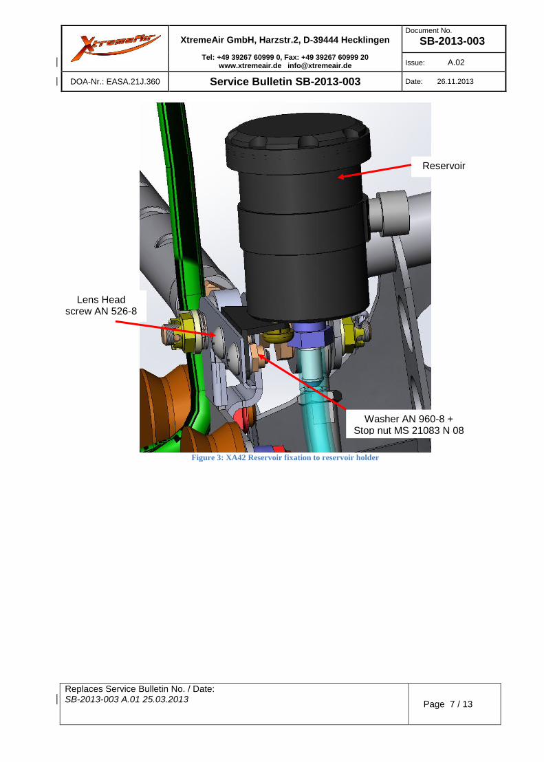
11. Assemble the reservoir assembly to the reservoir holder. (See Figure 3)
12. Connect the blue brake hose between reservoir and master cylinder. (See Figure 1).
13. Reconnect the brake line from the aircraft to the master cylinder.
DOA-Nr.: EASA.21J.360 Service Bulletin SB-2013-003 Date: 26.11.2013
Replaces Service Bulletin No. / Date: SB-2013-003 A.01 25.03.2013
Page 3 / 13
For XA41 Disassembly
1. Disconnect the brake line from the master brake cylinder and collect all the brake fluid.
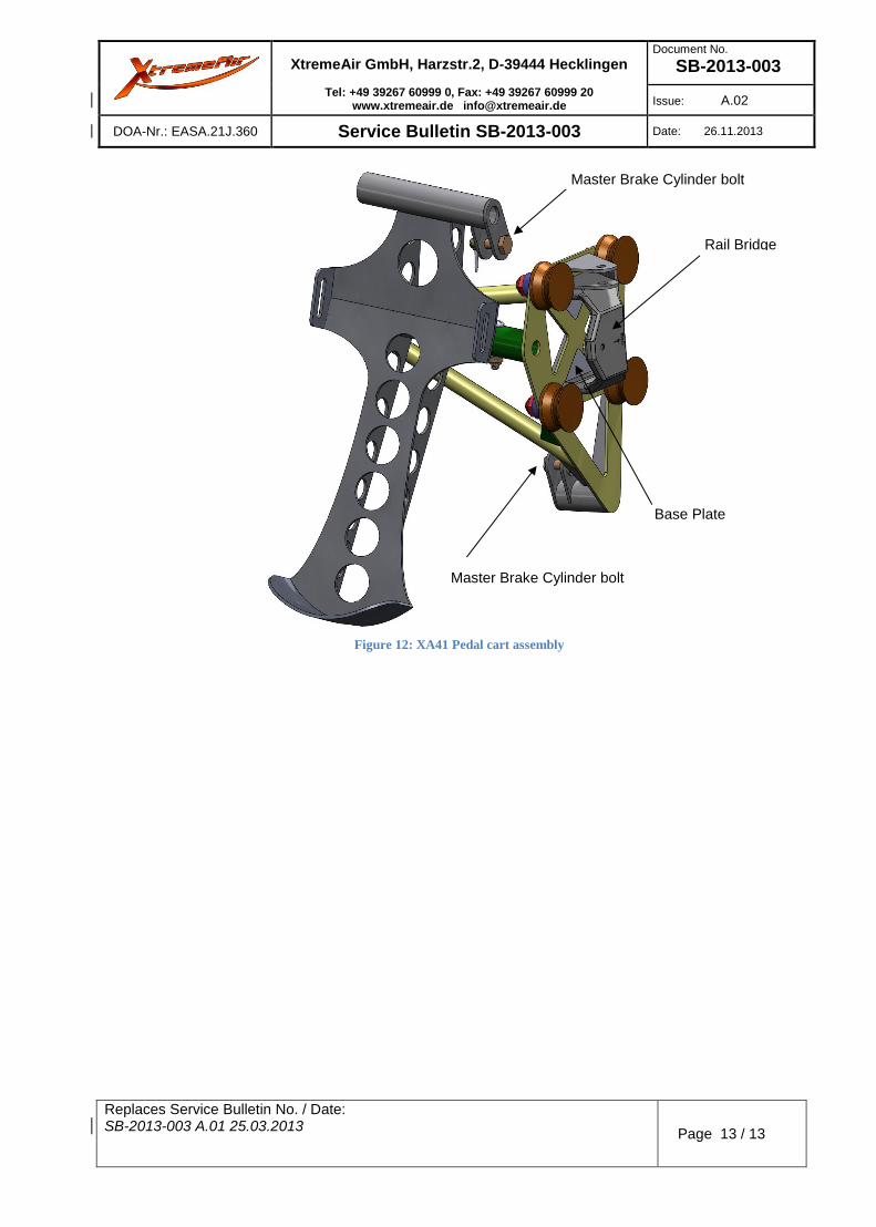
2. Remove the master brake cylinder from the pedal by removing the two (2) AN4-7A bolts. Make sure the split pin is removed before loosening the nuts.
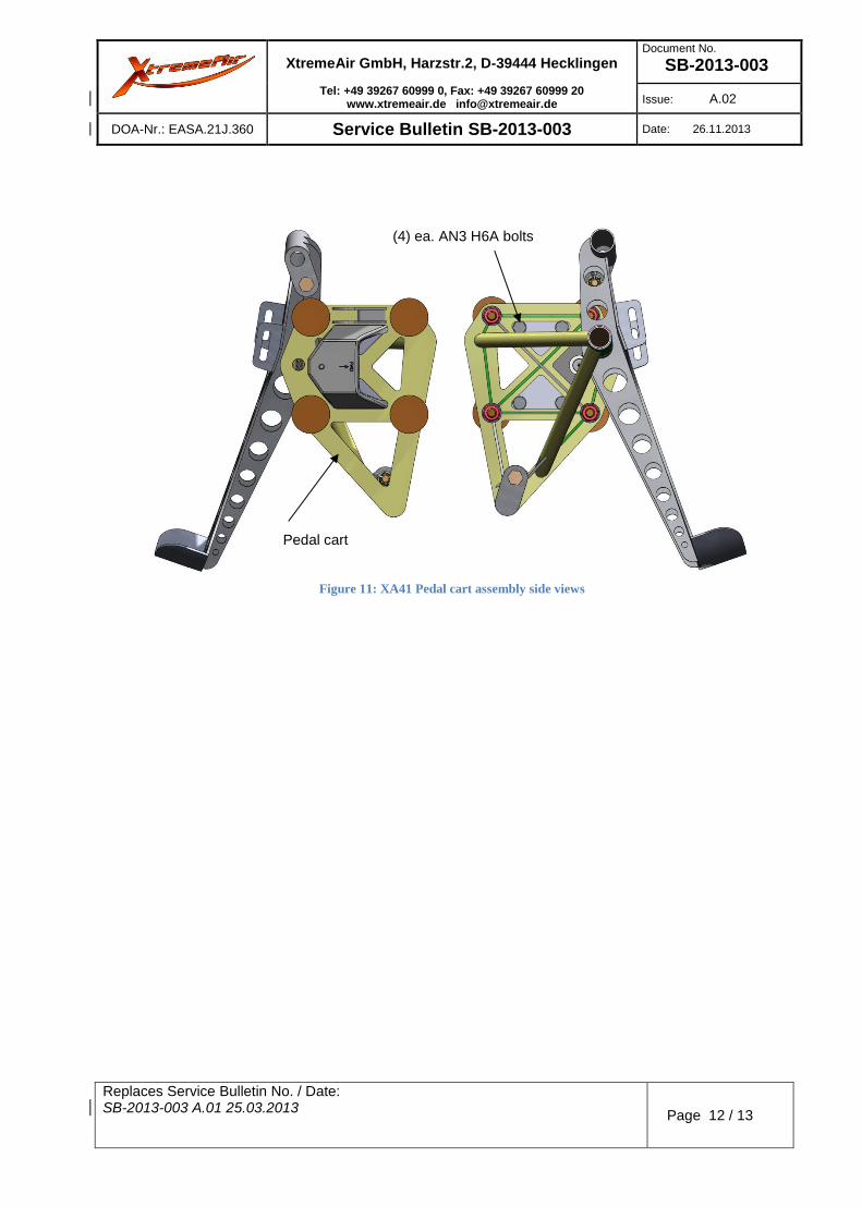
3. Remove the four (4) AN3H6A bolts with AN960-10L washers from the base plates. Make sure to remove the safety wire before loosening the bolts.
4. Loosen the four (4) nuts from the rollers, remove bridge and rollers simultaneously and separate the pedal from the rail.
5. Disconnect the connection from the length adjustment rod by removing the AN4-7A bolt. Make sure the split pin is removed before loosening the nut.
6. Disassemble the pedal from the cart by removing the AN23-18A screw and by removing the axial tube.
7. Send the pedal cart to XtremeAir for modification. Once the modified pedal cart is received proceed with the assembly.
Assembly
1. Reassemble the pedal to the cart by using a new MS21083N stop nut.
2. Reassemble the connection with the length adjustment rod. Make sure the bolt is inserted from the bottom. Replace the 2x12 split pin. (See Figure 5).
3. Place the two base plates from the inside in the upper and lower triangular cut-outs of the pedal cart. Make sure the base plates are seated properly in the cart. The outer plane of the base plate shall be flush with the outer plane of the cart (see Figure 6 left).
4. Place the cart next to the rail 5. Insert the two (2) concentric rollers in the upper locations of
the cart and position the rail bridge simultaneously. Make sure the arrow on the rail bridge is pointing forward.
6. Insert the two (2) eccentric rollers in the bottom locations of the cart (see Figure 7).
7. Reattach the two (2) base plates to the rail bridge using four (4) AN3H6A bolts with AN960-10L washers. Torque to 5 Nm (45 in.lbs.). Make sure the base plates stay flush with the cart as shown in Figure 6.
8. Adjust the eccentric rollers to eliminate any play between the rollers and the rail.
9. Torque all roller nuts to 15 Nm (11 ft.lbs.) 10. Safety wire the AN3H6A bolts of each base plate in pairs. 11. Set the basic Master Cylinder 694-3 length to 170mm (See
DOA-Nr.: EASA.21J.360 Service Bulletin SB-2013-003 Date: 26.11.2013
Replaces Service Bulletin No. / Date: SB-2013-003 A.01 25.03.2013
Page 4 / 13
12. Assemble the new master cylinder making sure the fitting connections face forward. Use a new split pin to secure the bolts.
13. Assemble the reservoir assembly to the reservoir holder. (See Figure 8)
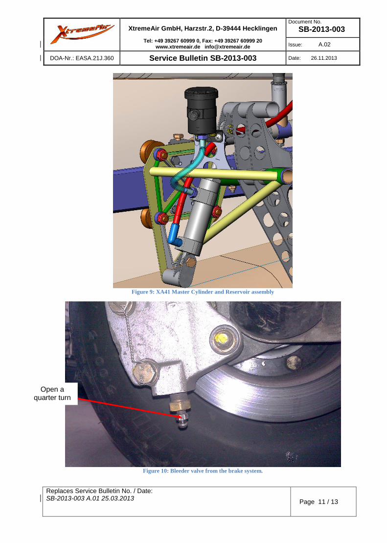
14. Connect the brake blue hose between reservoir and master cylinder. (See Figure 9).
15. Reconnect the brake line from the aircraft to the master cylinder.
16. Seal all fasteners with locking varnish. For XA41 and XA42 Replenishment of brake fluid
1. Unscrew the reservoir top 2. Remove the inner membrane 3. The best method to fill and bleed aircraft brakes is from the
bottom up. Use Mil-H-5606 red hydraulic fluid. 4. Loosely connect a 1/8” ID clear hose to the brake caliper
bleeder screw from your brake fluid source. 5. An oil can used exclusively for this purpose is to be used.
Pump the oil can until the hose is full of fluid, with no air bubbles.
6. Tightly secure the hose to the bleeder valve, while opening it a quarter turn. (See Figure 10)
7. Pump fluid into the system until it fills the brake cylinder reservoir. This is the case when the reservoir sight glass turns red.
8. Tighten the bleeder valve screw, remove the hose, and reseal the reservoir by reinserting the membrane and screwing the reservoir top.
9. Check your work by ensuring that the reservoir is full and that you have a “hard pedal”.
10. If you have a “soft-pedal”, pump the brakes several times. Many times that will fix the problem. If the problem persists, repeat the above process.
Report accomplishment of the service bulletin via email to [email protected], stating aircraft serial number and registration number.
Approval: The technical information contained in this document has been
approved under the authority of EASA Design Organisation Approval no. EASA.21J.360.


![[ 4758 ] - 526](https://static.documents.pub/doc/80x56/61a5c7874dcc62027b35deaf/-4758-526.jpg)


