Page 1
PRO-AROMATIC DYE COMPONENTS FOR DYE-SENSITIZED SOLAR CELLS: THIENOTHIOPHENE AND INDOLIZINE
by George Andrew Puneky
A thesis submitted to the faculty of The University of Mississippi in partial fulfillment of the requirements of the Sally McDonnell Barksdale Honors College
Oxford May 2015
Approved by
__________________________________
Advisor: Professor Jared Delcamp
__________________________________
Reader: Professor Davita Watkins
__________________________________
Reader: Professor Jason Ritchie
Page 2
ii
© 2015 George Andrew Puneky
ALL RIGHTS RESERVED
Page 3
iii
ACKNOWLEDGEMESNTS
We thank the Mississippi NSF-EPSCOR program (EPS-0903787), the University of
Mississippi, and the UM Sally McDonnell Barksdale Honors College for funding this
project. In addition, G.A.P would like to thank Dr. Jared Delcamp and the team of
undergraduate and graduate researchers involved with the Delcamp Group for their
continued support and guidance toward completion of this project.
Page 4
iv
ABSTRACT Four D-π-A dyes based on a 3,4-thienothiophene π-bridge were synthesized for use in
dye-sensitized solar cells (DSCs). The pro-aromatic building block 3,4-thienothiophene
has been reported to stabilize dye excited-state oxidation potentials. This lowering of
excited-state energy levels permits for increased absorption into the near-infrared (NIR)
region using relatively low molecular weight dyes. Strong donor functionality based on
triaryl- and diarylamines are employed in the dye designs to raise both the ground and
excited-state oxidation potentials to values capable of generating DSC devices with good
open-circuit voltages. Solubility, aggregation, and TiO2 surface protection were
addressed by examining an ethylhexyl alkyl chain in comparison to a basic ethyl chain on
the thienothiophene bridge. Through this minor structural modification, a drastic increase
in overall efficiency of up to 7.8% is observed. Again in an attempt to stabilize dye
excited-state oxidation potentials through competing local aromaticity, a fifth dye was
synthesized to incorporate a pro-aromatic indolizine-based donor moiety. Preliminary
optical and electrochemical results with regards to the indolizine-based dye appear to be
undesirable in terms of prospective cell performance. These preliminary results are
believed to stem from the excessively strong electron withdrawing tricyanofuran acceptor
unit seen in this dye.
Page 5
v
TABLE OF CONTENTS
INTRODUCTION……………………………………………………….………………01 RESULTS AND DISCUSSION: THIENOTHIOPHE…………………………..………11 SYNTHESIS: DP1, DP2, PB1, AND PB2……………………………..………..11 OPTICAL AND ELECTROCHEMICAL PROPERTIES……………..………..14 COMPUTATIONAL STUDIES………………………….……………..……….17
PHOTOVOLTAIC PERFORMANCE…………………………………………..18 RESULTS AND DISCUSSION: INDOLIZINE…………………………...….….……..22
SYNTHESIS: DP3…………………………………………………..…………...22 OPTICAL AND ELECTROCHEMICAL PROPERTIES………………..……..23 PHOTOVOLTAIC PERFORMANCE……………………………………….….26 CONCLUSION…………………………………………………………………………..27 REFERENCES…………………………………………………………………………..29 EXPERIMENTAL PROCEDURES……………………………………………………..32 GENERAL INFORMATION…………………………………….……….……..32 SYNTHETIC PROCEDURES: DP1 and DP2……………………….……….…32 SYNTHETIC PROCEDURES: DP3……………………………………….…....40
COMPUTATIONAL DETAILS……………………….………………….…….45 PHOTOVOLTAIC CHARACTERIZATION………………..………………….45 DEVICE FABRICATION……………………………………...………………..46 1H NMR DATA………………………………..……………………….………………..47 INPUT FILES FOR DP1 AND DP2…………………………………...………………..54
Page 6
1
Introduction.
Since the dawn of the Industrial Revolution society has evolved with the vague
assumption that mankind would always have access to a sufficient supply of energy
resources. The vast majority of consumed energy in the world is generated by three fossil
fuels: natural gas, coal, and petroleum. Other major sources of energy being exploited in
modern day consist of nuclear power and renewable energy (hydroelectric, wind, solar).
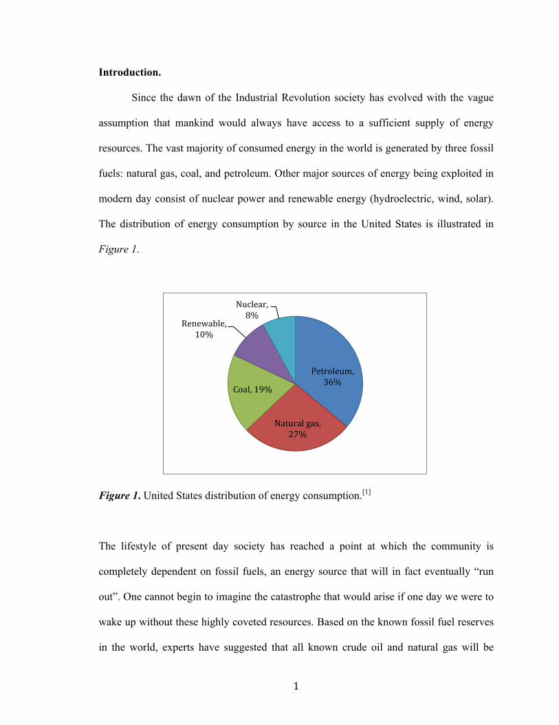
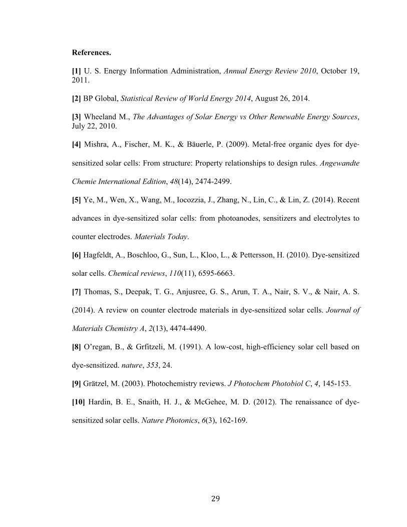
The distribution of energy consumption by source in the United States is illustrated in
Figure 1.
Figure 1. United States distribution of energy consumption.[1]
The lifestyle of present day society has reached a point at which the community is
completely dependent on fossil fuels, an energy source that will in fact eventually “run
out”. One cannot begin to imagine the catastrophe that would arise if one day we were to
wake up without these highly coveted resources. Based on the known fossil fuel reserves
in the world, experts have suggested that all known crude oil and natural gas will be
Petroleum, 36%
Natural gas, 27%
Coal, 19%
Renewable, 10%
Nuclear, 8%
Page 7
2
extracted roughly within the next 50 years, while coal mining will persist for 100 years or
more.[2] This dark foreshadowing of a near future deprived of energy has set the stage for
present day science to develop various solutions.
At the current state of scientific knowledge, solar energy is the clear frontrunner
in the race to power the future. Although there are multiple reasons why the potential of
solar energy trumps the broadly used fossil fuels of today, such as labor and pollution, it
is essentially a futile argument in the sense that these fossil fuels will soon be non-
existent. A renewable source of energy is needed. Among the forms of renewable energy,
solar energy possesses an impressive resume in light of others such as hydroelectric and
wind. Hydroelectric power generally relies on the use of large-scale dams that carry a
very expensive price tag and give rise to possible geological damage and negative effects
on wildlife. In light of the already mentioned downfalls of hydroelectric power, the most
important deterrent of its use is the fact that the production of hydroelectric power has
reached near capacity, with little room for growth.[3] Wind energy also has its associated
cons such as turbine maintenance, region specific noise, and the requirement of large
areas of land.[3] Solar energy stands as a solution to virtually all problems associated with
other forms of renewable energy. Solar panels require essentially no maintenance and do
not cause environmental damage or pollution. Costs associated with the installation of
solar panels may not be inexpensive initially, but the accumulation of electricity savings
will soon surmount to pay for the initial investment. Unlike water and wind, sunlight can
be found nearly anywhere on earth.[3] Given this, and the fact that solar panels are easily
installed on existing unused space such as rooftops, the option of solar energy is very
versatile.
Page 8
3
Solar cells that are commercially available today are primarily composed of fairly
expensive inorganic silicon semiconductors. The use of organic solar cells appears to be a
cost efficient alternative to the presently used silicon-based solar cells. Dye-sensitized
solar cells (DSCs) have recently attracted much attention as a promising future
technology implementing an organic-based solar cell design. Functional ruthenium-based
complexes, zinc-porphyrins, and metal free organic donor-acceptor systems are the three
main classes of dye sensitizers currently used in DSC. Ruthenium-based dyes have been
show to produce impressive efficiencies, but at a high expense and associated risks in
difficult synthesis and purification, while zinc-porphyrin dyes have been associated with
a limited light harvesting range.[5] The alternative class of metal free organic dyes are
currently at a developmental state of slightly lower efficiency but provide a promising
future outlook in their low expense, tunable and easily synthesized molecular structures,
and typically higher molar extinction coefficients compared to that of their competitors.[6]
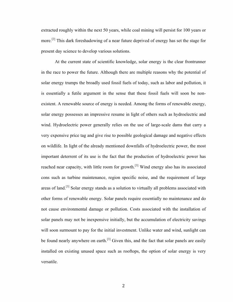
Figure 2 illustrates a typical donor-π-bridge-acceptor (D-π-A) structural design for metal
free organic dyes, along with electron transfer arrows that are further detailed in Figure 3.
Figure 2. Organic D-π-A dye design illustrating the pathway of electron injection.[4]
Donor π - Bridge Acceptor TiO2
Dye/Sensitizer Semiconductor
e-e-hv
Page 9
4
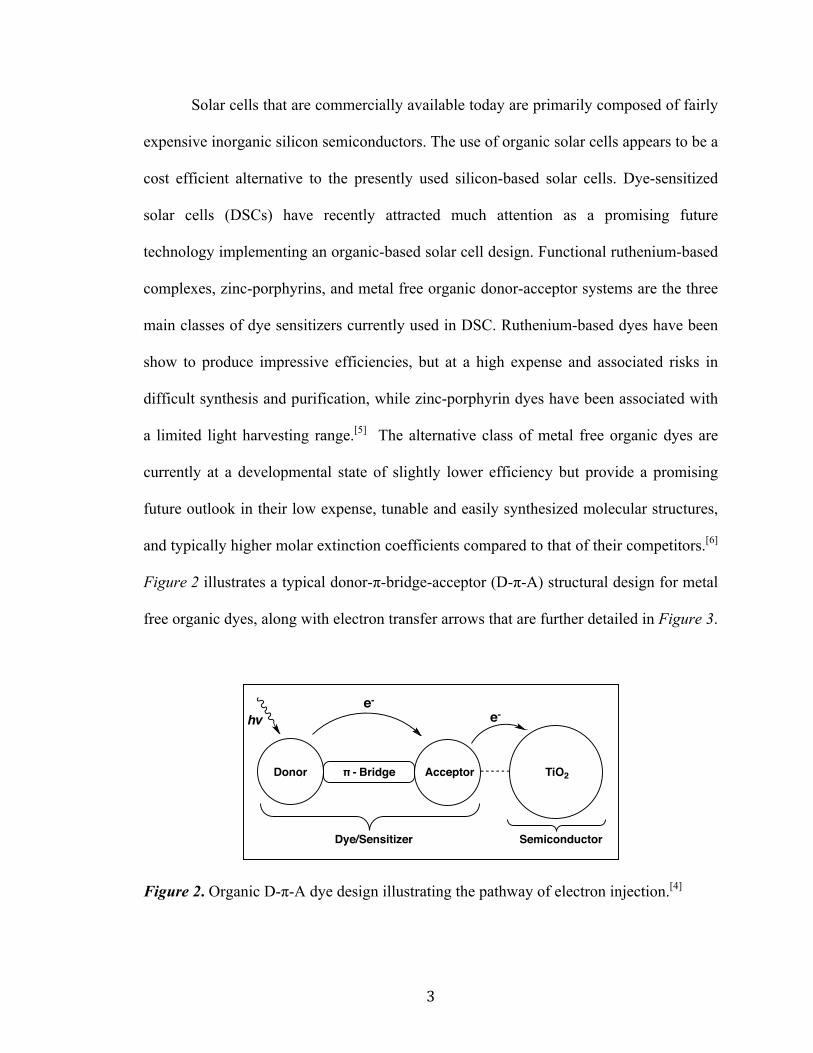
Figure 3. DSC schematic illustrating the general working mechanism of the cell.[7]
Figure 3 illustrates a DSC schematic and the basic pathways necessary to the
device’s function. Initial photon absorption by the dye-sensitizer induces electron
excitation from the ground-state (S+/S) to the excited-state (S+/S*). The excited-state
electron is then injected into the conduction band of a metal oxide electrode (TiO2). After
injection, the electron is conducted to the anode and then travels via an external
connection to the cathode counter electrode. Reduction of the redox couple (commonly I-
/I3-)[9] takes place at the cathode and is used to complete the circuit upon electron
donation to regenerate the ground-state dye.[6]
The main parameter of interest in the process illustrated in Figure 3 is the photon
conversion efficiency (η, PCE), which represents how efficiently sunlight is converted to
usable electrical energy. PCE is determined to be the product of the short circuit current
(JSC), the open circuit voltage (VOC), and the fill factor (FF).
Page 10
5
𝜼 = 𝑱𝒔𝒄𝑽𝒐𝒄𝑭𝑭
Equation 1. PCE equation.
The maximum JSC is relative to how much light can be absorbed by the sensitizer, while
the maximum VOC is a measurement of the potential difference between the conduction
band of the metal oxide and the valence band of the redox couple. FF is a variable that is
largely dependent on the internal resistance present in the device.
In order to develop a highly efficient cell, all thermodynamic and kinetic
parameters must be accounted for with regards to dye structure. An energetically
favorable driving force is necessary for electron injection (ΔGinj) from the excited-state
sensitizer into the metal oxide conduction band as well as a favorable driving force for
the regeneration of the ground-state sensitizer (ΔGreg). It is noted that a minimal driving
force of ~200 mV is needed for an efficient injection and regeneration event.[6] If these
driving forces are not sufficient, counter-productive alternate electron transfer pathways
can emerge. The main interfering pathways of concern consist of: photorelaxation of
excited-state electrons back to the ground-state, unfavorable direct electron transfer
between the metal oxide and sensitizer (the “back-reaction”), and unfavorable cyclical
electron transfer between the metal oxide and redox shuttle (recombination). Common
dye structural features incorporated to correct these potential issues are positioning of the
high electron affinity donor subunit far away from the metal oxide surface in order to
slow the back-reaction, and the implementation of long alkyl chains to block
communication between the redox couple and metal oxide, thus diminishing
recombination.
Page 11
6
With fossil fuel resources quickly fading, a new source of energy will be required
to fill the gap left by the world’s soon-to-be depleted oil reserves. Since the introduction
of DSCs in 1991,[8] tremendous efforts have been made to bring this new technology to
the forefront of alternative energy options.[6] For the major part of the past two decades,
devices using ruthenium-based sensitizers have dominated the DSC field, possessing the
best electronic parameters and providing cells of the highest efficiency.[10, 11, 12, 13] For the
first time in 2014, a purely organic dye, ADEKA-1,[14] and a porphyrin-based dye,
SM315,[15] were seen to surpass these ruthenium-based dyes with PCEs of 12.5% and
13.0% respectively. The success of these dyes are largely driven by the iterative use of
ubiquitous, modular D-π-A dye design. As previously mentioned, dyes of this nature are
typically much more cost efficient as they do not rely on expensive metals and commonly
make use of straightforward synthetic schemes. PCE improvements over these impressive
devices is reasonable and would be aided through the careful development of building
blocks allowing tunable access to the near-infrared (NIR, ~750 nm) region of the solar
spectrum.[10] Pro-aromatic building blocks are promising dye components that allow for
tunability into the NIR region using dyes of relatively low molecular weights.
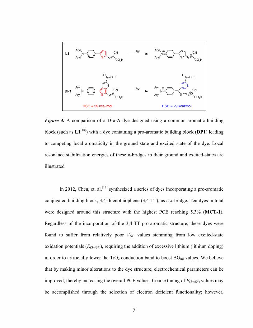
Certain sensitizers have incorporated the use of pro-aromatic structures.[15,16,17]
These structures benefit from an increase in stability provided by an area of local
aromaticity present in their excited-state. This phenomenon is illustrated with a
comparison of L1 with that of DP1 in Figure 4. As a result of pro-aromatic excited state
stabilization, photoexcitation occurs at significantly lower photonic energies, whereas the
ground state energy level is relatively unaffected leading to a narrowing of the optical
band gap.
Page 12
7
Figure 4. A comparison of a D-π-A dye designed using a common aromatic building
block (such as L1[18]) with a dye containing a pro-aromatic building block (DP1) leading
to competing local aromaticity in the ground state and excited state of the dye. Local
resonance stabilization energies of these π-bridges in their ground and excited-states are
illustrated.
In 2012, Chen, et. al.[17] synthesized a series of dyes incorporating a pro-aromatic
conjugated building block, 3,4-thienothiophene (3,4-TT), as a π-bridge. Ten dyes in total
were designed around this structure with the highest PCE reaching 5.3% (MCT-1).
Regardless of the incorporation of the 3,4-TT pro-aromatic structure, these dyes were
found to suffer from relatively poor VOC values stemming from low excited-state
oxidation potentials (E(S+/S*)), requiring the addition of excessive lithium (lithium doping)
in order to artificially lower the TiO2 conduction band to boost ΔGinj values. We believe
that by making minor alterations to the dye structure, electrochemical parameters can be
improved, thereby increasing the overall PCE values. Coarse tuning of E(S+/S*) values may
be accomplished through the selection of electron deficient functionality; however,
S
S
O OEt
NAryl
ArylCO2H
CN
SN
Aryl
ArylCO2H
CNS
NAryl
ArylCO2H
CN
S
S
O OEt
NAryl
ArylCO2H
CNhv
hvL1
DP1
RSE = 29 kcal/mol RSE = 29 kcal/mol
Page 13
8
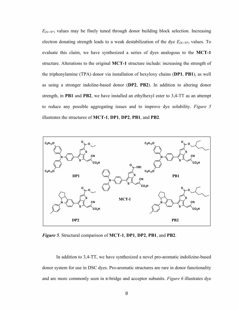
E(S+/S*) values may be finely tuned through donor building block selection. Increasing
electron donating strength leads to a weak destabilization of the dye E(S+/S*) values. To
evaluate this claim, we have synthesized a series of dyes analogous to the MCT-1
structure. Alterations to the original MCT-1 structure include: increasing the strength of
the triphenylamine (TPA) donor via installation of hexyloxy chains (DP1, PB1), as well
as using a stronger indoline-based donor (DP2, PB2). In addition to altering donor
strength, in PB1 and PB2, we have installed an ethylhexyl ester to 3,4-TT as an attempt
to reduce any possible aggregating issues and to improve dye solubility. Figure 5
illustrates the structures of MCT-1, DP1, DP2, PB1, and PB2.
Figure 5. Structural comparison of MCT-1, DP1, DP2, PB1, and PB2.
In addition to 3,4-TT, we have synthesized a novel pro-aromatic indolizine-based
donor system for use in DSC dyes. Pro-aromatic structures are rare in donor functionality
and are more commonly seen in π-bridge and acceptor subunits. Figure 6 illustrates dye
S
S
O OEt
N
CO2H
CN
MCT-1
S
S
O O
N
CO2H
CN
S
S
O O
N
C6H13O
C6H13O
CO2H
CN
PB1
PB2
S
S
O O
N
CO2H
CN
S
S
O O
N
C6H13O
C6H13O
CO2H
CN
DP1
DP2
Page 14
9
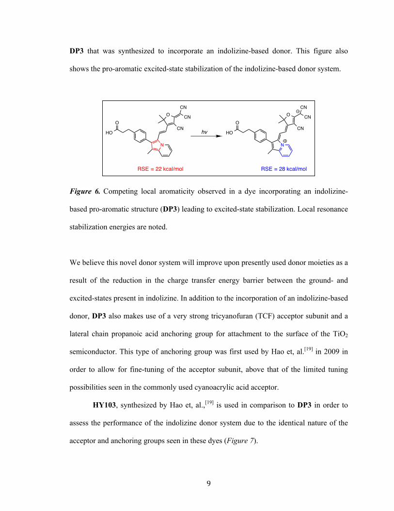
DP3 that was synthesized to incorporate an indolizine-based donor. This figure also
shows the pro-aromatic excited-state stabilization of the indolizine-based donor system.
Figure 6. Competing local aromaticity observed in a dye incorporating an indolizine-
based pro-aromatic structure (DP3) leading to excited-state stabilization. Local resonance
stabilization energies are noted.
We believe this novel donor system will improve upon presently used donor moieties as a
result of the reduction in the charge transfer energy barrier between the ground- and
excited-states present in indolizine. In addition to the incorporation of an indolizine-based
donor, DP3 also makes use of a very strong tricyanofuran (TCF) acceptor subunit and a
lateral chain propanoic acid anchoring group for attachment to the surface of the TiO2
semiconductor. This type of anchoring group was first used by Hao et, al.[19] in 2009 in
order to allow for fine-tuning of the acceptor subunit, above that of the limited tuning
possibilities seen in the commonly used cyanoacrylic acid acceptor.
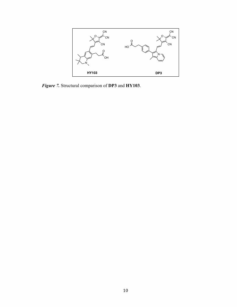
HY103, synthesized by Hao et, al.,[19] is used in comparison to DP3 in order to
assess the performance of the indolizine donor system due to the identical nature of the
acceptor and anchoring groups seen in these dyes (Figure 7).
N
HO
OO
CN
CN
CN
N
HO
OO
CN
CN
CN
RSE = 22 kcal/mol RSE = 28 kcal/mol
hv
Page 15
10
Figure 7. Structural comparison of DP3 and HY103.
O
CN
CN
CN
N
N
HO
OO
CN
CN
CN
HY103 DP3
OH
O
Page 16
11
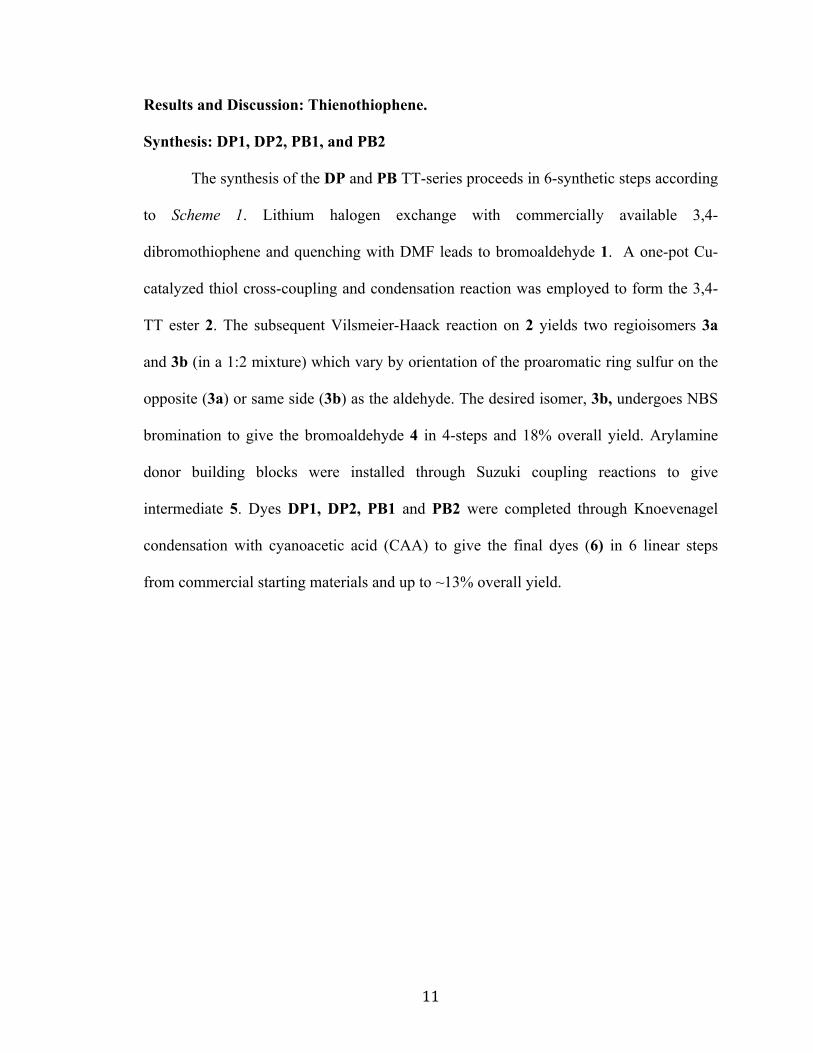
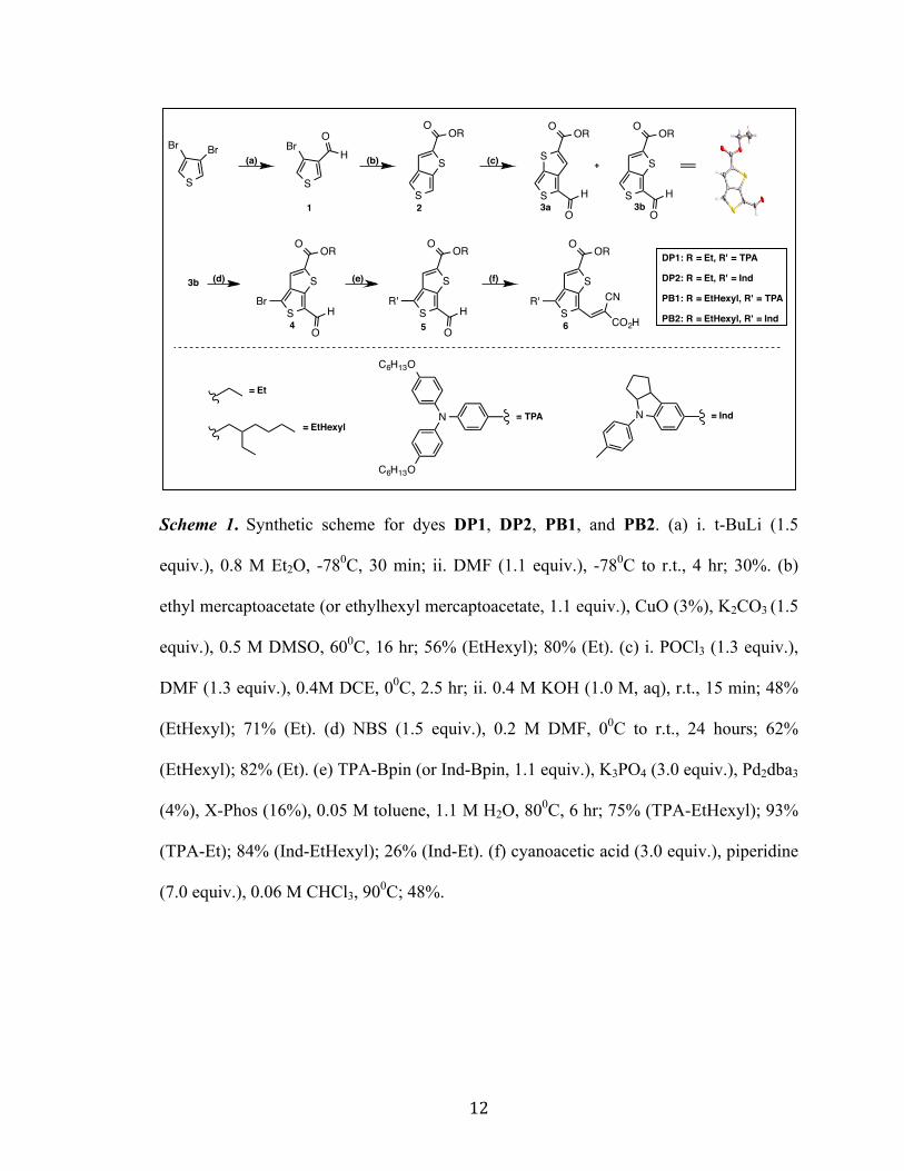
Results and Discussion: Thienothiophene.
Synthesis: DP1, DP2, PB1, and PB2
The synthesis of the DP and PB TT-series proceeds in 6-synthetic steps according
to Scheme 1. Lithium halogen exchange with commercially available 3,4-
dibromothiophene and quenching with DMF leads to bromoaldehyde 1. A one-pot Cu-
catalyzed thiol cross-coupling and condensation reaction was employed to form the 3,4-
TT ester 2. The subsequent Vilsmeier-Haack reaction on 2 yields two regioisomers 3a
and 3b (in a 1:2 mixture) which vary by orientation of the proaromatic ring sulfur on the
opposite (3a) or same side (3b) as the aldehyde. The desired isomer, 3b, undergoes NBS
bromination to give the bromoaldehyde 4 in 4-steps and 18% overall yield. Arylamine
donor building blocks were installed through Suzuki coupling reactions to give
intermediate 5. Dyes DP1, DP2, PB1 and PB2 were completed through Knoevenagel
condensation with cyanoacetic acid (CAA) to give the final dyes (6) in 6 linear steps
from commercial starting materials and up to ~13% overall yield.
Page 17
12
Scheme 1. Synthetic scheme for dyes DP1, DP2, PB1, and PB2. (a) i. t-BuLi (1.5
equiv.), 0.8 M Et2O, -780C, 30 min; ii. DMF (1.1 equiv.), -780C to r.t., 4 hr; 30%. (b)
ethyl mercaptoacetate (or ethylhexyl mercaptoacetate, 1.1 equiv.), CuO (3%), K2CO3 (1.5
equiv.), 0.5 M DMSO, 600C, 16 hr; 56% (EtHexyl); 80% (Et). (c) i. POCl3 (1.3 equiv.),
DMF (1.3 equiv.), 0.4M DCE, 00C, 2.5 hr; ii. 0.4 M KOH (1.0 M, aq), r.t., 15 min; 48%
(EtHexyl); 71% (Et). (d) NBS (1.5 equiv.), 0.2 M DMF, 00C to r.t., 24 hours; 62%
(EtHexyl); 82% (Et). (e) TPA-Bpin (or Ind-Bpin, 1.1 equiv.), K3PO4 (3.0 equiv.), Pd2dba3
(4%), X-Phos (16%), 0.05 M toluene, 1.1 M H2O, 800C, 6 hr; 75% (TPA-EtHexyl); 93%
(TPA-Et); 84% (Ind-EtHexyl); 26% (Ind-Et). (f) cyanoacetic acid (3.0 equiv.), piperidine
(7.0 equiv.), 0.06 M CHCl3, 900C; 48%.
S
BrH
O
S
S
OOR
S
S
O OR
H
O
S
S
O OR
H
O
Br
S
Br Br
N
C6H13O
C6H13O
N
S
S
O OR
H
O
R'S
S
O OR
R'
CO2H
CN
= TPA = Ind
= Et
= EtHexyl
(f)(d) (e)
(c)(b)(a)
4 5 6
1 2 3aS
S
O OR
H
O3b
+
3b
DP1: R = Et, R' = TPA
DP2: R = Et, R' = Ind
PB1: R = EtHexyl, R' = TPA
PB2: R = EtHexyl, R' = Ind
Page 18
13
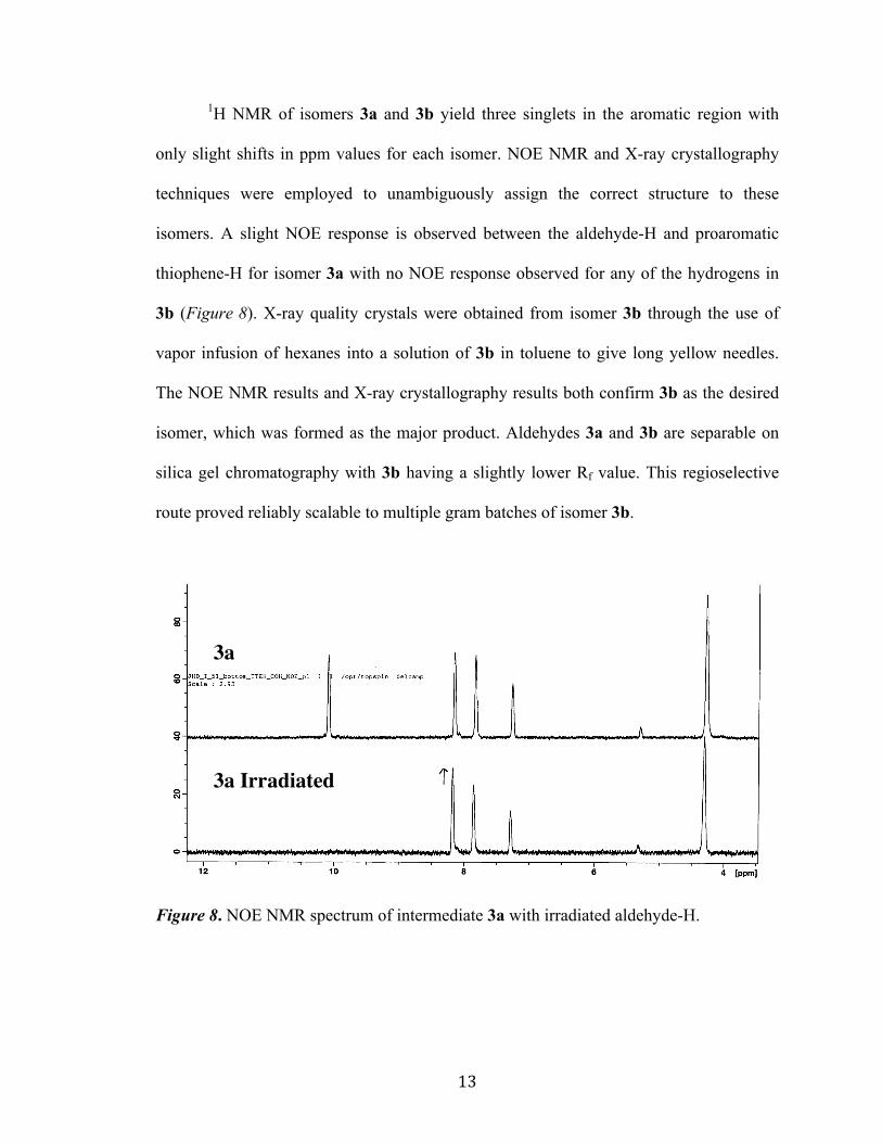
1H NMR of isomers 3a and 3b yield three singlets in the aromatic region with
only slight shifts in ppm values for each isomer. NOE NMR and X-ray crystallography
techniques were employed to unambiguously assign the correct structure to these
isomers. A slight NOE response is observed between the aldehyde-H and proaromatic
thiophene-H for isomer 3a with no NOE response observed for any of the hydrogens in
3b (Figure 8). X-ray quality crystals were obtained from isomer 3b through the use of
vapor infusion of hexanes into a solution of 3b in toluene to give long yellow needles.
The NOE NMR results and X-ray crystallography results both confirm 3b as the desired
isomer, which was formed as the major product. Aldehydes 3a and 3b are separable on
silica gel chromatography with 3b having a slightly lower Rf value. This regioselective
route proved reliably scalable to multiple gram batches of isomer 3b.
Figure 8. NOE NMR spectrum of intermediate 3a with irradiated aldehyde-H.
3a
3a Irradiated
Page 19
14
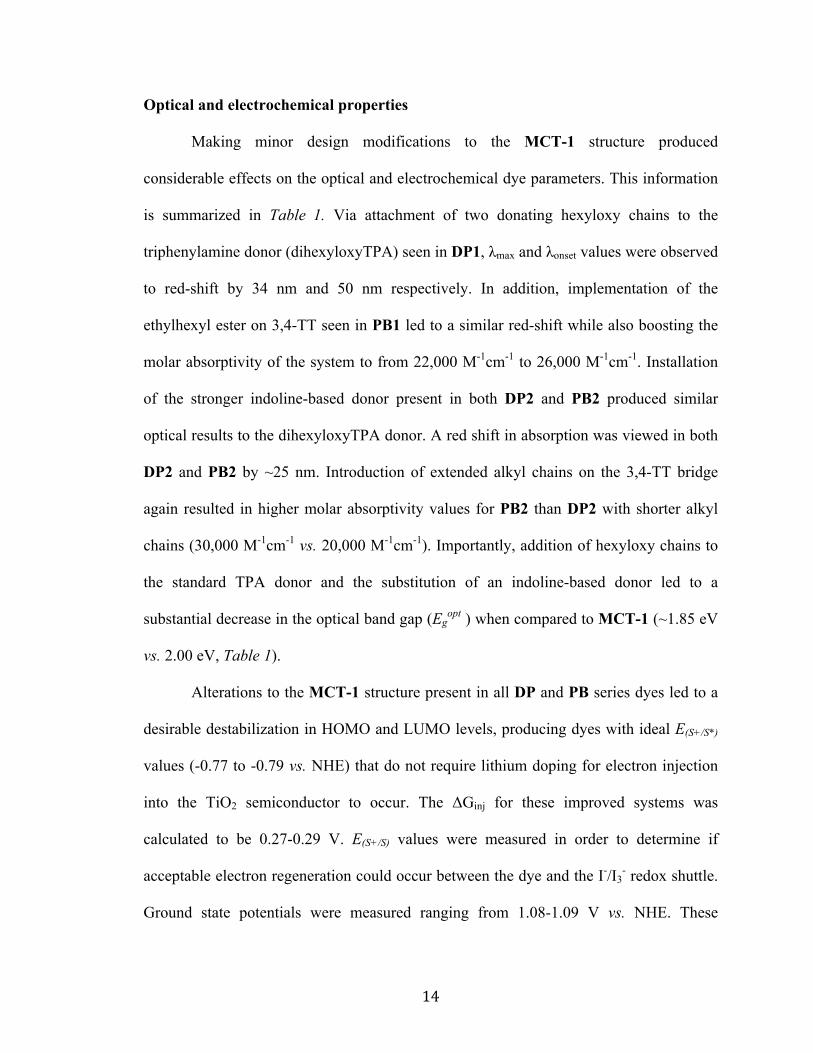
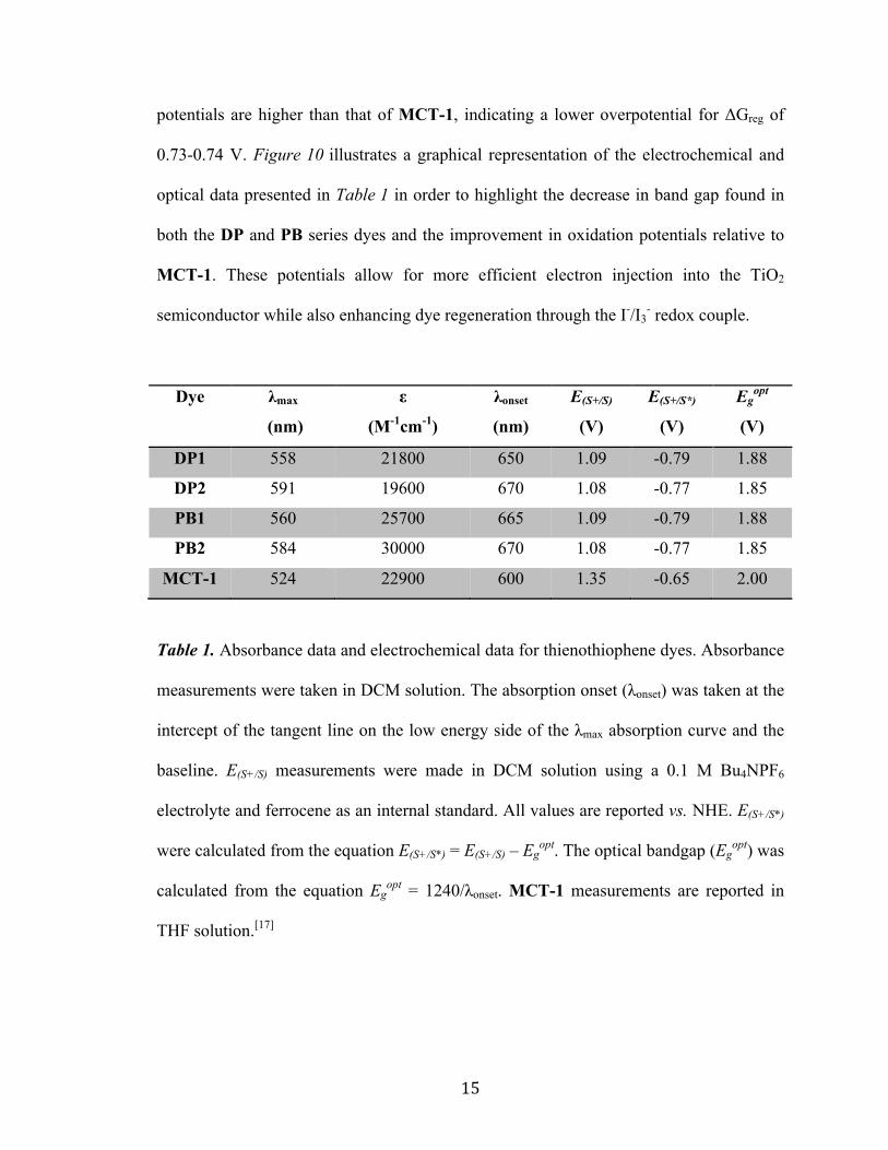
Optical and electrochemical properties
Making minor design modifications to the MCT-1 structure produced
considerable effects on the optical and electrochemical dye parameters. This information
is summarized in Table 1. Via attachment of two donating hexyloxy chains to the
triphenylamine donor (dihexyloxyTPA) seen in DP1, λmax and λonset values were observed
to red-shift by 34 nm and 50 nm respectively. In addition, implementation of the
ethylhexyl ester on 3,4-TT seen in PB1 led to a similar red-shift while also boosting the
molar absorptivity of the system to from 22,000 M-1cm-1 to 26,000 M-1cm-1. Installation
of the stronger indoline-based donor present in both DP2 and PB2 produced similar
optical results to the dihexyloxyTPA donor. A red shift in absorption was viewed in both
DP2 and PB2 by ~25 nm. Introduction of extended alkyl chains on the 3,4-TT bridge
again resulted in higher molar absorptivity values for PB2 than DP2 with shorter alkyl
chains (30,000 M-1cm-1 vs. 20,000 M-1cm-1). Importantly, addition of hexyloxy chains to
the standard TPA donor and the substitution of an indoline-based donor led to a
substantial decrease in the optical band gap (Egopt ) when compared to MCT-1 (~1.85 eV
vs. 2.00 eV, Table 1).
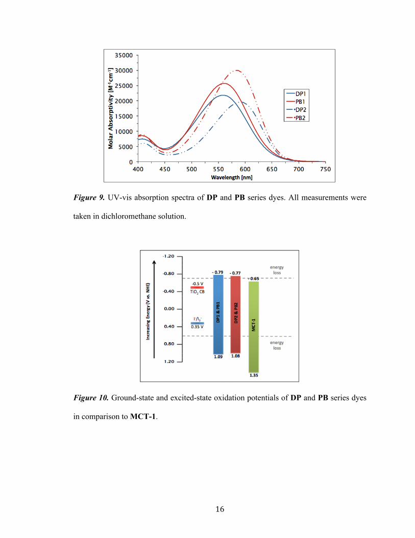
Alterations to the MCT-1 structure present in all DP and PB series dyes led to a
desirable destabilization in HOMO and LUMO levels, producing dyes with ideal E(S+/S*)
values (-0.77 to -0.79 vs. NHE) that do not require lithium doping for electron injection
into the TiO2 semiconductor to occur. The ΔGinj for these improved systems was
calculated to be 0.27-0.29 V. E(S+/S) values were measured in order to determine if
acceptable electron regeneration could occur between the dye and the I-/I3- redox shuttle.
Ground state potentials were measured ranging from 1.08-1.09 V vs. NHE. These
Page 20
15
potentials are higher than that of MCT-1, indicating a lower overpotential for ΔGreg of
0.73-0.74 V. Figure 10 illustrates a graphical representation of the electrochemical and
optical data presented in Table 1 in order to highlight the decrease in band gap found in
both the DP and PB series dyes and the improvement in oxidation potentials relative to
MCT-1. These potentials allow for more efficient electron injection into the TiO2
semiconductor while also enhancing dye regeneration through the I-/I3- redox couple.
Dye λmax
(nm)
ε
(M-1cm-1)
λonset
(nm)
E(S+/S)
(V)
E(S+/S*)
(V)
Egopt
(V)
DP1 558 21800 650 1.09 -0.79 1.88
DP2 591 19600 670 1.08 -0.77 1.85
PB1 560 25700 665 1.09 -0.79 1.88
PB2 584 30000 670 1.08 -0.77 1.85
MCT-1 524 22900 600 1.35 -0.65 2.00
Table 1. Absorbance data and electrochemical data for thienothiophene dyes. Absorbance
measurements were taken in DCM solution. The absorption onset (λonset) was taken at the
intercept of the tangent line on the low energy side of the λmax absorption curve and the
baseline. E(S+/S) measurements were made in DCM solution using a 0.1 M Bu4NPF6
electrolyte and ferrocene as an internal standard. All values are reported vs. NHE. E(S+/S*)
were calculated from the equation E(S+/S*) = E(S+/S) – Egopt. The optical bandgap (Eg
opt) was
calculated from the equation Egopt = 1240/λonset. MCT-1 measurements are reported in
THF solution.[17]
Page 21
16
Figure 9. UV-vis absorption spectra of DP and PB series dyes. All measurements were
taken in dichloromethane solution.
Figure 10. Ground-state and excited-state oxidation potentials of DP and PB series dyes
in comparison to MCT-1.
Page 22
17
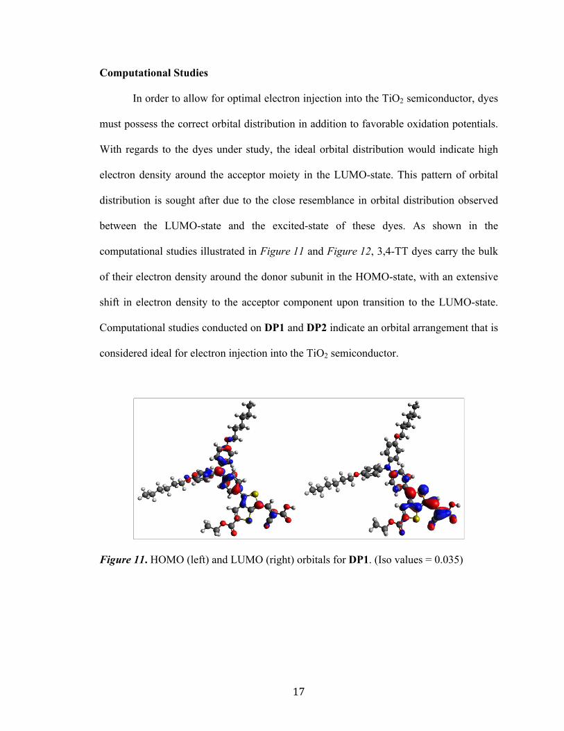
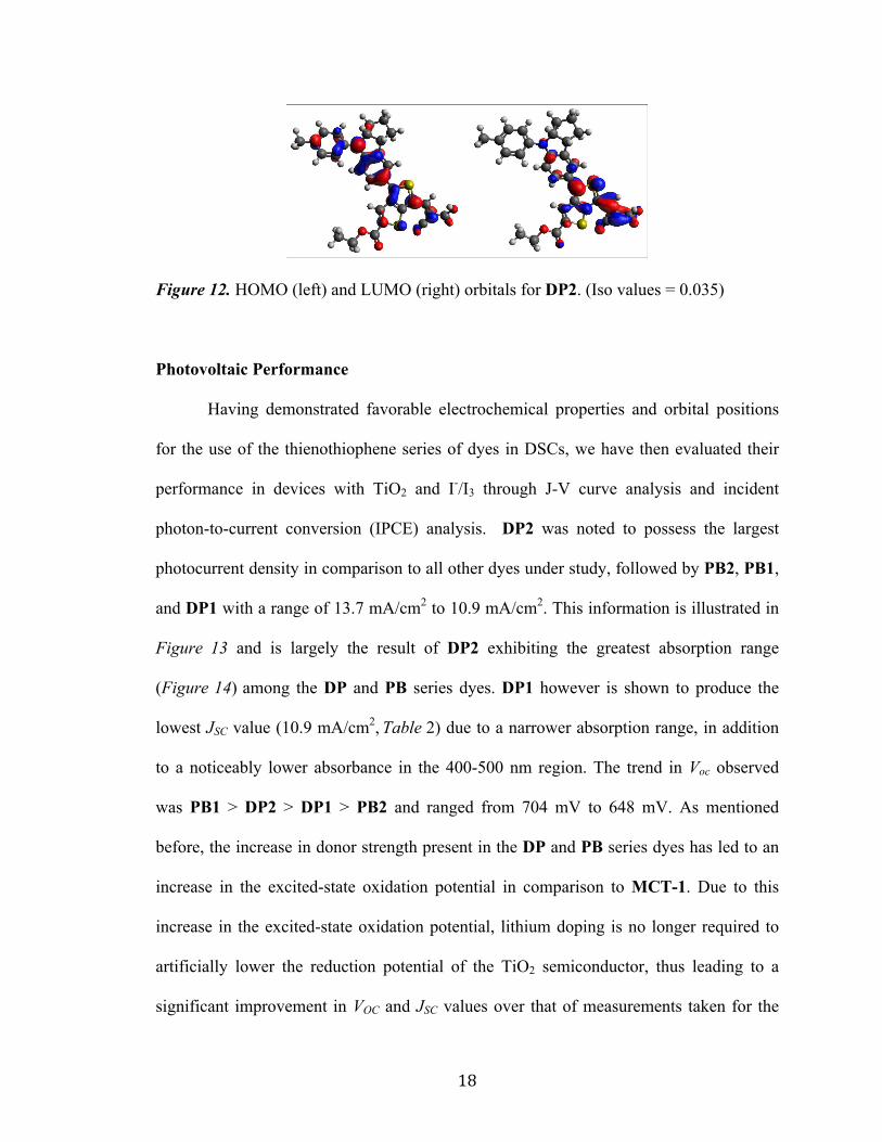
Computational Studies
In order to allow for optimal electron injection into the TiO2 semiconductor, dyes
must possess the correct orbital distribution in addition to favorable oxidation potentials.
With regards to the dyes under study, the ideal orbital distribution would indicate high
electron density around the acceptor moiety in the LUMO-state. This pattern of orbital
distribution is sought after due to the close resemblance in orbital distribution observed
between the LUMO-state and the excited-state of these dyes. As shown in the
computational studies illustrated in Figure 11 and Figure 12, 3,4-TT dyes carry the bulk
of their electron density around the donor subunit in the HOMO-state, with an extensive
shift in electron density to the acceptor component upon transition to the LUMO-state.
Computational studies conducted on DP1 and DP2 indicate an orbital arrangement that is
considered ideal for electron injection into the TiO2 semiconductor.
Figure 11. HOMO (left) and LUMO (right) orbitals for DP1. (Iso values = 0.035)
Page 23
18
Figure 12. HOMO (left) and LUMO (right) orbitals for DP2. (Iso values = 0.035)
Photovoltaic Performance
Having demonstrated favorable electrochemical properties and orbital positions
for the use of the thienothiophene series of dyes in DSCs, we have then evaluated their
performance in devices with TiO2 and I-/I3 through J-V curve analysis and incident
photon-to-current conversion (IPCE) analysis. DP2 was noted to possess the largest
photocurrent density in comparison to all other dyes under study, followed by PB2, PB1,
and DP1 with a range of 13.7 mA/cm2 to 10.9 mA/cm2. This information is illustrated in
Figure 13 and is largely the result of DP2 exhibiting the greatest absorption range
(Figure 14) among the DP and PB series dyes. DP1 however is shown to produce the
lowest JSC value (10.9 mA/cm2, Table 2) due to a narrower absorption range, in addition
to a noticeably lower absorbance in the 400-500 nm region. The trend in Voc observed
was PB1 > DP2 > DP1 > PB2 and ranged from 704 mV to 648 mV. As mentioned
before, the increase in donor strength present in the DP and PB series dyes has led to an
increase in the excited-state oxidation potential in comparison to MCT-1. Due to this
increase in the excited-state oxidation potential, lithium doping is no longer required to
artificially lower the reduction potential of the TiO2 semiconductor, thus leading to a
significant improvement in VOC and JSC values over that of measurements taken for the
Page 24
19
MCT-1 cell. This comprehensive enhancement in electronic parameters produced an
increase in overall device performance ranging from 5.61% (DP1) to 7.41% (DP2).
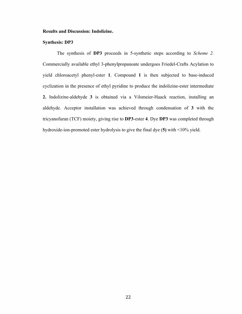
Electron lifetime measurements were recorded with regards to the DP and PB
series of dyes in order to better understand the observed VOC trends by evaluating the
effect of dye structure on electron recombination with the redox shuttle. As stated by Ito,
et. al.,[20] addition of long alkyl-substituted groups to the structure of a dye molecule
should produce an increase in electron lifetime measurements as the result of preventative
recombination of the oxidized redox shuttle with TiO2 semiconductor electrons. These
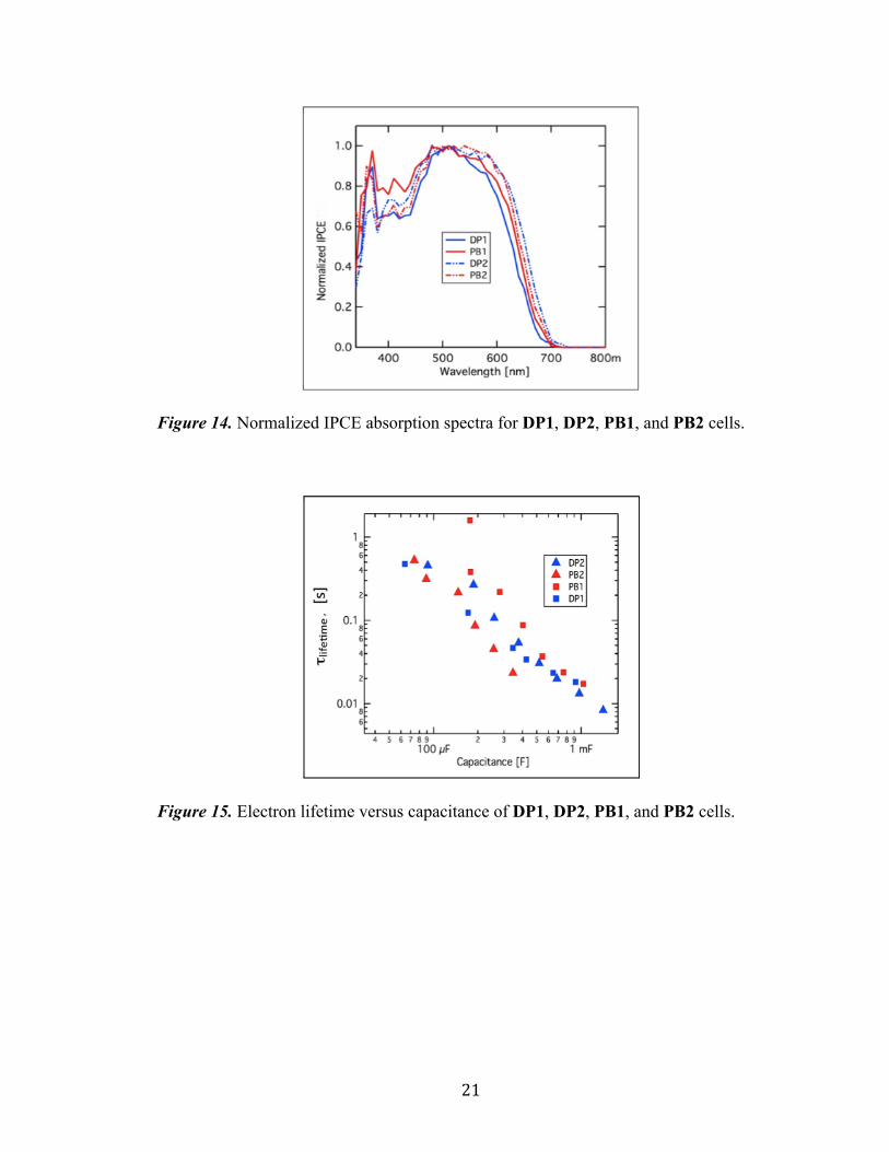
observations were found to not apply to our 3,4-TT system as seen in Figure 15. DP1 and
DP2 were noted to demonstrate longer electron lifetime measurements than that of the
ethylhexyl-substituted PB2. This suggests PCE diminishing aggregative effects are not
inhibitive for the 3,4-TT π-bridge dyes as the more compact DP2 gives improved electron
lifetimes presumably through a closer packing of the dye on the TiO2 surface. The
expected results were obtained in the case of PB1, showing the highest electron lifetime
measurements among all of the dyes tested. This is conventional with PB1 due to the
combined sterics present in its ethylhexyl-substituted 3,4-TT π-bridge and its
dihexyloxyTPA donor. This slow recombination rate allows PB1 to generate a higher
voltage relative to the other dyes in this series.
Page 25
20
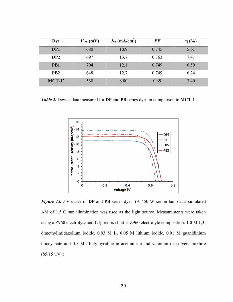
Dye VOC (mV) JSC (mA/cm2) FF η (%)
DP1 680 10.9 0.745 5.61
DP2 697 13.7 0.763 7.41
PB1 704 12.1 0.749 6.50
PB2 648 12.7 0.749 6.24
MCT-1a 560 8.80 0.69 3.40
Table 2. Device data measured for DP and PB series dyes in comparison to MCT-1.
Figure 13. J-V curve of DP and PB series dyes. (A 450 W xenon lamp at a simulated
AM of 1.5 G sun illumination was used as the light source. Measurements were taken
using a Z960 electrolyte and I-/I3- redox shuttle. Z960 electrolyte composition: 1.0 M 1,3-
dimethylimidazolium iodide, 0.03 M I2, 0.05 M lithium iodide, 0.01 M guanidinium
thiocyanate and 0.5 M t-butylpyridine in acetonitrile and valeronitrile solvent mixture
(85:15 v/v).)
Page 26
21
Figure 14. Normalized IPCE absorption spectra for DP1, DP2, PB1, and PB2 cells.
Figure 15. Electron lifetime versus capacitance of DP1, DP2, PB1, and PB2 cells.
Page 27
22
Results and Discussion: Indolizine.
Synthesis: DP3
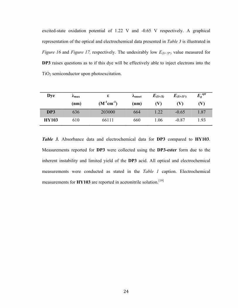
The synthesis of DP3 proceeds in 5-synthetic steps according to Scheme 2.
Commercially available ethyl 3-phenylpropanoate undergoes Friedel-Crafts Acylation to
yield chloroacetyl phenyl-ester 1. Compound 1 is then subjected to base-induced
cyclization in the presence of ethyl pyridine to produce the indolizine-ester intermediate
2. Indolizine-aldehyde 3 is obtained via a Vilsmeier-Haack reaction, installing an
aldehyde. Acceptor installation was achieved through condensation of 3 with the
tricyanofuran (TCF) moiety, giving rise to DP3-ester 4. Dye DP3 was completed through
hydroxide-ion-promoted ester hydrolysis to give the final dye (5) with <10% yield.
Page 28
23
Scheme 2. Synthetic scheme for dye DP3. (a) bromoacetyl chloride (1.6 equiv.), 1.8 M
DCM, AlCl3 (2.7 equiv.), -50C to 00C, 30 min, reflux, 1 hr; carried directly into following
reaction. (b) i. ethyl pyridine (1.0 equiv.), 2.0 M acetone, reflux, 24 hr; ii. 24%
NaOEt:EtOH (4.0 equiv.), reflux, 24 hr; iii. H2SO4 (2.0 mL), EtOH (excess), reflux, 24
hr; 60%. (c) i. 0.4 M DCE, DMF (1.1 equiv.), POCl3 (1.1 equiv.), 00C to r.t., 1.5 hr; ii.
0.4 M KOH (1.0 M, aq), r.t., 15 min; 60%. (d) TCF (1.1 equiv.), 4-aminophenol (0.4
equiv.), AcOH (0.03 mL), toluene (5.0 mL), reflux, 24 hr; 42%. (e) LiOH (5.0 mL), THF
(5.0 mL), r.t., 3.5 hr; , <10%.
Optical and Electrochemical Properties
Implementation of an indolizine-based donor system in place of the
tetrahydroquinoline donor seen in HY103 produced significant changes in optical and
electrochemical dye parameters. Table 3 illustrates the measured absorbance and
electrochemical data for DP3 in comparison to HY103. Substitution of the indolizine-
based donor in DP3 was observed to produce a notable red-shift in λmax of 26 nm.
Minimal difference in λonset was recognized. Electrochemical parameters for DP3 were
determined to be less than ideal, demonstrating a ground-state oxidation potential and a
N
EtO
O
N
EtO
O
HO
EtO
O
EtO
O
BrO
N
HO
O
R
N
EtO
O
R
O
NC
CN
CN
(c) (d) (e)
(b)(a)
3 4 5
1 2
2
= R
Page 29
24
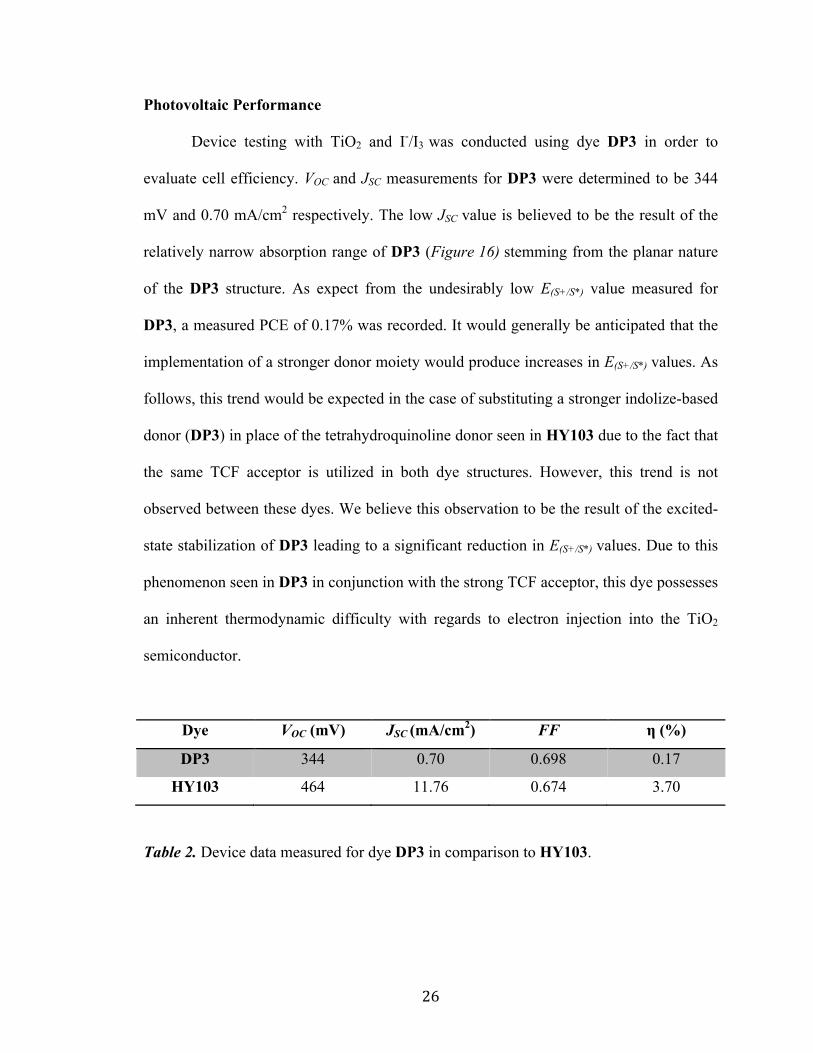
excited-state oxidation potential of 1.22 V and -0.65 V respectively. A graphical
representation of the optical and electrochemical data presented in Table 3 is illustrated in
Figure 16 and Figure 17, respectively. The undesirably low E(S+/S*) value measured for
DP3 raises questions as to if this dye will be effectively able to inject electrons into the
TiO2 semiconductor upon photoexcitation.
Dye λmax
(nm)
ε
(M-1cm-1)
λonset
(nm)
E(S+/S)
(V)
E(S+/S*)
(V)
Egopt
(V)
DP3 636 203000 664 1.22 -0.65 1.87
HY103 610 66111 660 1.06 -0.87 1.93
Table 3. Absorbance data and electrochemical data for DP3 compared to HY103.
Measurements reported for DP3 were collected using the DP3-ester form due to the
inherent instability and limited yield of the DP3 acid. All optical and electrochemical
measurements were conducted as stated in the Table 1 caption. Electrochemical
measurements for HY103 are reported in acetonitrile solution.[19]
Page 30
25
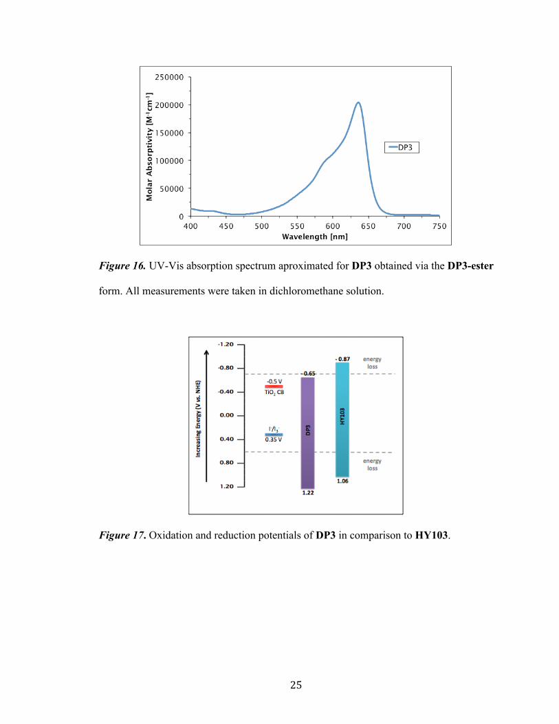
Figure 16. UV-Vis absorption spectrum aproximated for DP3 obtained via the DP3-ester
form. All measurements were taken in dichloromethane solution.
Figure 17. Oxidation and reduction potentials of DP3 in comparison to HY103.
Page 31
26
Photovoltaic Performance
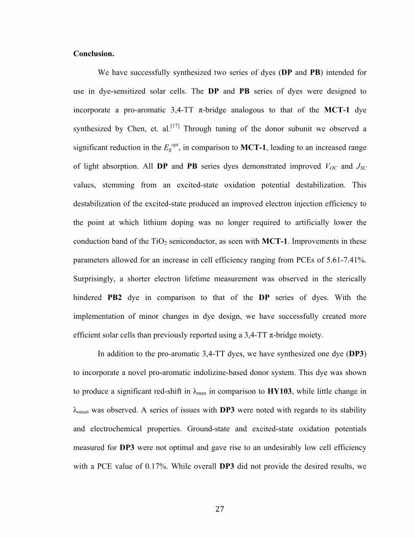
Device testing with TiO2 and I-/I3 was conducted using dye DP3 in order to
evaluate cell efficiency. VOC and JSC measurements for DP3 were determined to be 344
mV and 0.70 mA/cm2 respectively. The low JSC value is believed to be the result of the
relatively narrow absorption range of DP3 (Figure 16) stemming from the planar nature
of the DP3 structure. As expect from the undesirably low E(S+/S*) value measured for
DP3, a measured PCE of 0.17% was recorded. It would generally be anticipated that the
implementation of a stronger donor moiety would produce increases in E(S+/S*) values. As
follows, this trend would be expected in the case of substituting a stronger indolize-based
donor (DP3) in place of the tetrahydroquinoline donor seen in HY103 due to the fact that
the same TCF acceptor is utilized in both dye structures. However, this trend is not
observed between these dyes. We believe this observation to be the result of the excited-
state stabilization of DP3 leading to a significant reduction in E(S+/S*) values. Due to this
phenomenon seen in DP3 in conjunction with the strong TCF acceptor, this dye possesses
an inherent thermodynamic difficulty with regards to electron injection into the TiO2
semiconductor.
Dye VOC (mV) JSC (mA/cm2) FF η (%)
DP3 344 0.70 0.698 0.17
HY103 464 11.76 0.674 3.70
Table 2. Device data measured for dye DP3 in comparison to HY103.
Page 32
27
Conclusion.
We have successfully synthesized two series of dyes (DP and PB) intended for
use in dye-sensitized solar cells. The DP and PB series of dyes were designed to
incorporate a pro-aromatic 3,4-TT π-bridge analogous to that of the MCT-1 dye
synthesized by Chen, et. al.[17] Through tuning of the donor subunit we observed a
significant reduction in the Egopt, in comparison to MCT-1, leading to an increased range
of light absorption. All DP and PB series dyes demonstrated improved VOC and JSC
values, stemming from an excited-state oxidation potential destabilization. This
destabilization of the excited-state produced an improved electron injection efficiency to
the point at which lithium doping was no longer required to artificially lower the
conduction band of the TiO2 seniconductor, as seen with MCT-1. Improvements in these
parameters allowed for an increase in cell efficiency ranging from PCEs of 5.61-7.41%.
Surprisingly, a shorter electron lifetime measurement was observed in the sterically
hindered PB2 dye in comparison to that of the DP series of dyes. With the
implementation of minor changes in dye design, we have successfully created more
efficient solar cells than previously reported using a 3,4-TT π-bridge moiety.
In addition to the pro-aromatic 3,4-TT dyes, we have synthesized one dye (DP3)
to incorporate a novel pro-aromatic indolizine-based donor system. This dye was shown
to produce a significant red-shift in λmax in comparison to HY103, while little change in
λonset was observed. A series of issues with DP3 were noted with regards to its stability
and electrochemical properties. Ground-state and excited-state oxidation potentials
measured for DP3 were not optimal and gave rise to an undesirably low cell efficiency
with a PCE value of 0.17%. While overall DP3 did not provide the desired results, we
Page 33
28
believe these issues may be easily adjusted by implementation of a weaker acceptor
moiety possessing intermediate electron withdrawing properties in addition to the
standard cyanoacrylic acid acceptor. We believe this change would successfully increase
the excited-state oxidation potential measured for DP3 to the point at which efficient
electron injection into the TiO2 semiconductor would be probable. Future work has been
gauged toward further experimentation with indolizine-based donors with the intention of
correcting issues observed in DP3.
Page 34
29
References.
[1] U. S. Energy Information Administration, Annual Energy Review 2010, October 19, 2011. [2] BP Global, Statistical Review of World Energy 2014, August 26, 2014. [3] Wheeland M., The Advantages of Solar Energy vs Other Renewable Energy Sources, July 22, 2010. [4] Mishra, A., Fischer, M. K., & Bäuerle, P. (2009). Metal‐free organic dyes for dye‐
sensitized solar cells: From structure: Property relationships to design rules. Angewandte
Chemie International Edition, 48(14), 2474-2499.
[5] Ye, M., Wen, X., Wang, M., Iocozzia, J., Zhang, N., Lin, C., & Lin, Z. (2014). Recent
advances in dye-sensitized solar cells: from photoanodes, sensitizers and electrolytes to
counter electrodes. Materials Today.
[6] Hagfeldt, A., Boschloo, G., Sun, L., Kloo, L., & Pettersson, H. (2010). Dye-sensitized
solar cells. Chemical reviews, 110(11), 6595-6663.
[7] Thomas, S., Deepak, T. G., Anjusree, G. S., Arun, T. A., Nair, S. V., & Nair, A. S.
(2014). A review on counter electrode materials in dye-sensitized solar cells. Journal of
Materials Chemistry A, 2(13), 4474-4490.
[8] O’regan, B., & Grfitzeli, M. (1991). A low-cost, high-efficiency solar cell based on
dye-sensitized. nature, 353, 24.
[9] Grätzel, M. (2003). Photochemistry reviews. J Photochem Photobiol C, 4, 145-153.
[10] Hardin, B. E., Snaith, H. J., & McGehee, M. D. (2012). The renaissance of dye-
sensitized solar cells. Nature Photonics, 6(3), 162-169.
Page 35
30
[11] Chen, C. Y., Wang, M., Li, J. Y., Pootrakulchote, N., Alibabaei, L., Ngoc-le, C. H.,
... & Grätzel, M. (2009). Highly efficient light-harvesting ruthenium sensitizer for thin-
film dye-sensitized solar cells. ACS nano, 3(10), 3103-3109.
[12] Carballo, M. S., Urbani, M., Chandiran, A. K., González-Rodríguez, D., Vázquez,
P., Grätzel, M., ... & Torres, T. (2014). Branched and bulky substituted ruthenium
sensitizers for dye-sensitized solar cells. Dalton Transactions, 43(40), 15085-15091.
[13] Chiba, Y., Islam, A., Watanabe, Y., Komiya, R., Koide, N., & Han, L. (2006). Dye-
sensitized solar cells with conversion efficiency of 11.1%. Japanese Journal of Applied
Physics, 45(7L), L638.
[14] Kakiage, K., Aoyama, Y., Yano, T., Otsuka, T., Kyomen, T., Unno, M., & Hanaya,
M. (2014). An achievement of over 12 percent efficiency in an organic dye-sensitized
solar cell. Chemical Communications, 50(48), 6379-6381.
[15] Mathew, S., Yella, A., Gao, P., Humphry-Baker, R., Curchod, B. F., Ashari-Astani,
N., ... & Grätzel, M. (2014). Dye-sensitized solar cells with 13% efficiency achieved
through the molecular engineering of porphyrin sensitizers. Nature chemistry, 6(3), 242-
247.
[16] Franco, S., Garín, J., Martínez de Baroja, N., Pérez-Tejada, R., Orduna, J., Yu, Y., &
Lira-Cantú, M. (2012). New D− π–A-Conjugated Organic Sensitizers Based on 4 H-
Pyran-4-ylidene Donors for Highly Efficient Dye-Sensitized Solar Cells. Organic letters,
14(3), 752-755.
[17] Chen, Y. C., Chou, H. H., Tsai, M. C., Chen, S. Y., Lin, J. T., Yao, C. F., & Chen,
K. (2012). Thieno [3, 4‐b] thiophene‐Based Organic Dyes for Dye‐Sensitized Solar Cells.
Chemistry-A European Journal, 18(17), 5430-5437.
Page 36
31
[18] Liu, W. H., Wu, I. C., Lai, C. H., Lai, C. H., Chou, P. T., Li, Y. T., ... & Chi, Y.
(2008). Simple organic molecules bearing a 3, 4-ethylenedioxythiophene linker for
efficient dye-sensitized solar cells. Chemical Communications, (41), 5152-5154.
[19] Hao, Y., Yang, X., Cong, J., Tian, H., Hagfeldt, A., & Sun, L. (2009). Efficient near
infrared D–π–A sensitizers with lateral anchoring group for dye-sensitized solar cells.
Chemical Communications, (27), 4031-4033.
[20] Ito, S., Miura, H., Uchida, S., Takata, M., Sumioka, K., Liska, P., ... & Grätzel, M.
(2008). High-conversion-efficiency organic dye-sensitized solar cells with a novel
indoline dye. Chemical Communications, (41), 5194-5196.
[21] Frisch, M. J., Trucks, G. W., Schlegel, H. B., Scuseria, G. E., Robb, M. A.,
Cheeseman, J. R., ... & Cross, J. B. (2009). Gaussian 09, revision A. 1. Gaussian Inc.,
Wallingford, CT.
[22] Becke, A. D. (1993). Density‐functional thermochemistry. III. The role of exact
exchange. The Journal of Chemical Physics, 98(7), 5648-5652.
[23] Miehlich, B., Savin, A., Stoll, H., & Preuss, H. (1989). Results obtained with the
correlation energy density functionals of Becke and Lee, Yang and Parr. Chemical
Physics Letters, 157(3), 200-206.
[24] Fuller, L. S., Iddon, B., & Smith, K. A. (1997). Thienothiophenes. Part 2. 1
Synthesis, metallation and bromine→ lithium exchange reactions of thieno [3, 2-b]
thiophene and its polybromo derivatives. Journal of the Chemical Society, Perkin
Transactions 1, (22), 3465-3470.
Page 37
32
[25] Yu, Q. Y., Liao, J. Y., Zhou, S. M., Shen, Y., Liu, J. M., Kuang, D. B., & Su, C. Y.
(2011). Effect of hydrocarbon chain length of disubstituted triphenyl-amine-based
organic dyes on dye-sensitized solar cells. The Journal of Physical Chemistry C, 115(44),
22002-22008.
[26] Li, W., Wu, Y., Zhang, Q., Tian, H., & Zhu, W. (2012). DA-π-A featured sensitizers
bearing phthalimide and benzotriazole as auxiliary acceptor: effect on absorption and
charge recombination dynamics in dye-sensitized solar cells. ACS applied materials &
interfaces, 4(3), 1822-1830.
[27] Wang, H., Lu, Z., Lord, S. J., Willets, K. A., Bertke, J. A., Bunge, S. D., ... & Twieg,
R. J. (2007). The influence of tetrahydroquinoline rings in dicyanomethylenedihydro-
furan (DCDHF) single-molecule fluorophores. Tetrahedron, 63(1), 103-114.
[28] Huckaba, A. J., Giordano, F., McNamara, L. E., Dreux, K. M., Hammer, N. I.,
Tschumper, G. S., ... & Delcamp, J. H. (2014). Indolizine‐Based Donors as Organic
Sensitizer Components for Dye‐Sensitized Solar Cells. Advanced Energy Materials.
Page 38
33
Experimental Procedures.
General Information
All commercially obtained reagents were used as received. Thin-layer
chromatography (TLC) was conducted with Sigma T-6145 pre-coated Silica gen 60 F254
polyester sheets and visualized with UV. Flash column chromatography was performed
as described by Still using Sorbent Tech P60, 40-63 µm (230-400 mesh). 1H NMR
spectra were recorded on a Bruker Avance-300 (300MHz) spectrometer and are reported
in ppm using solvent as an internal standard (CDCL3 at 7.26 ppm). Data reported as: s =
singlet, d = doublet, t = triplet, q = quartet, p = pentet, m = multiplet, b = broad, ap =
apparent, dd = doublet of doublets; coupling constant(s) in Hz; integration. UV-Vis
Spectrum were measured with a Cary 5000 UV-Vis spectrometer. Cyclic voltammetry
was measured with a C-H Instruments electrochemical analyzer.
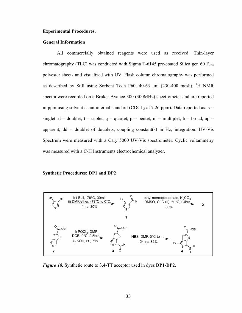
Synthetic Procedures: DP1 and DP2
Figure 18. Synthetic route to 3,4-TT acceptor used in dyes DP1-DP2.
S
BrH
O
S
S
OOEt
S
S
O OEt
H
OS
S
O OEt
H
O
Br
S
Br Br i) t-Buli, -78°C, 30minii) DMF/ether, -78°C to 0°C,
ethyl mercaptoacetate, K2CO3 DMSO, CuO (II), 60°C, 24hrs,
i) POCl3, DMFDCE, 0°C, 2.5hrs, NBS, DMF, 0°C to r.t.,
1
2 3 4
24hrs, 30% 80%
ii) KOH, r.t., 71% 24hrs, 82%
Page 39
34
Figure 19. Synthetic route to dye DP1. TPA donor A was contributed and synthesized by
Phillip Brogdon as reported in literature.[25] (PB1 = substitute ethylhexyl chain for Et)
Figure 20. Synthetic route to dye DP2. Indoline donor B was contributed and
synthesized by Phillip Brogdon as reported in literature.[26] (PB2 = substitute ethylhexyl
chain for Et)
S
S
O OEt
H
O
N
HxO
HxO
S
S
O OEt
N
HxO
HxO
CO2H
CN
S
S
O OEt
H
O
BrN
HxO
HxO
BpinK3PO4, Pd2dba3, X-phostoluene, H20, 80°C, 6hrs,+
piperidine, CHCl3, 90°C, 1hr48%
NC CO2H
5 DP1
A
593%
S
S
O OEt
N
CO2H
CNS
S
O OEt
HN
O
S
S
O OEt
H
O
Br
N BpinK3PO4, Pd2dba3, X-phostoluene, H20, 80°C, 6hrs,+
piperidine, CHCl3, 90°C, 1hr35%
NC CO2H
6 DP2
B
626%
Page 40
35
4-bromothiophene-3-carbaldehyde (1):[24] To a flame dried, N2 filled
200 mL round bottom flask was added dibromothiophene (4.6 mL, 41.3
mmol, 1.0 equiv.) and Et2O (50.0 mL). The flask was then cooled to -
78°C followed by addition of t-BuLi (36.4 mL, 62.0 mmol, 1.5 equiv.) dropwise over a
10 minute period. The solution was then stirred for 30 minutes. DMF (3.5 mL, 45.5
mmol, 1.1 equiv.) in Et2O (25.0 mL) was cooled to -78°C and added slowly to the
reaction mixture. The mixture was then allowed to warm to 0°C and stir for 4 hours
followed by extraction with excess Et2O/H2O and dried over MgSO4. The product was
purified through silica gel chromatography with 5% EA:Hx à 10% EA:Hx to give 4-
bromothiophene-3-carbaldehyde (2.28 g, 12.0 mmol, 30%). 1H NMR (300MHz, CDCl3)
δ 9.95 (s, 1H), 8.16 (d, J = 3.45 Hz, 1H), 7.36 (d, J = 3.45 Hz, 1H).
Ethyl thieno[3,4-b]thiophene-2-carboxylate (2):[24] To a 100 mL round
bottom flask was added 4-bromothiophene-3-carbaldehyde (2.28 g, 12.0
mmol, 1.0 equiv.), K2CO3 (3.82 g, 18.0 mmol, 1.5 equiv.), CuO (II) (0.03g,
0.36 mmol, 0.03 equiv.), and DMSO (24.0 mL, 0.5 M). The reaction
mixture was heated to 60°C followed by dropwise addition of ethyl mercaptoacetate (1.5
mL, 13.2 mmol, 1.1 equiv.). After stirring for 24 hours the product was purified using a
silica gel plug 5% NaOH à 10% NaOH to give ethyl thieno[3,4-b]thiophene-2-
carboxylate (2.0 g, 9.4 mmol, 79%). 1H NMR (300MHz, CDCl3) δ 7.70 (s, 1H), 7.59 (d, J
= 2.58 Hz, 1H), 7.29 (dd, J = 2.7 Hz, 0.9 Hz, 1H), 4.38 (q, J = 7.14 Hz, 2H), 1.40 (t, J =
7.14 Hz, 3H).
S
BrH
O
S
S
OOEt
Page 41
36
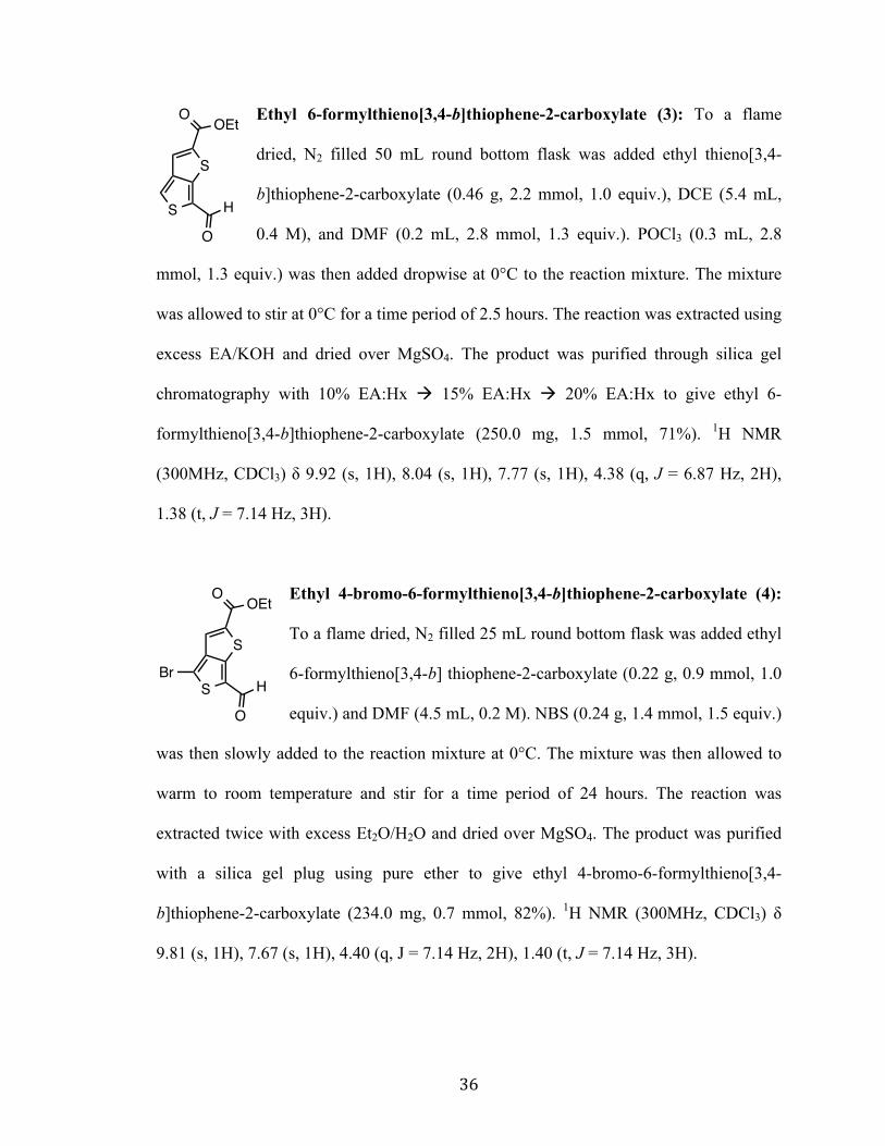
Ethyl 6-formylthieno[3,4-b]thiophene-2-carboxylate (3): To a flame
dried, N2 filled 50 mL round bottom flask was added ethyl thieno[3,4-
b]thiophene-2-carboxylate (0.46 g, 2.2 mmol, 1.0 equiv.), DCE (5.4 mL,
0.4 M), and DMF (0.2 mL, 2.8 mmol, 1.3 equiv.). POCl3 (0.3 mL, 2.8
mmol, 1.3 equiv.) was then added dropwise at 0°C to the reaction mixture. The mixture
was allowed to stir at 0°C for a time period of 2.5 hours. The reaction was extracted using
excess EA/KOH and dried over MgSO4. The product was purified through silica gel
chromatography with 10% EA:Hx à 15% EA:Hx à 20% EA:Hx to give ethyl 6-
formylthieno[3,4-b]thiophene-2-carboxylate (250.0 mg, 1.5 mmol, 71%). 1H NMR
(300MHz, CDCl3) δ 9.92 (s, 1H), 8.04 (s, 1H), 7.77 (s, 1H), 4.38 (q, J = 6.87 Hz, 2H),
1.38 (t, J = 7.14 Hz, 3H).
Ethyl 4-bromo-6-formylthieno[3,4-b]thiophene-2-carboxylate (4):
To a flame dried, N2 filled 25 mL round bottom flask was added ethyl
6-formylthieno[3,4-b] thiophene-2-carboxylate (0.22 g, 0.9 mmol, 1.0
equiv.) and DMF (4.5 mL, 0.2 M). NBS (0.24 g, 1.4 mmol, 1.5 equiv.)
was then slowly added to the reaction mixture at 0°C. The mixture was then allowed to
warm to room temperature and stir for a time period of 24 hours. The reaction was
extracted twice with excess Et2O/H2O and dried over MgSO4. The product was purified
with a silica gel plug using pure ether to give ethyl 4-bromo-6-formylthieno[3,4-
b]thiophene-2-carboxylate (234.0 mg, 0.7 mmol, 82%). 1H NMR (300MHz, CDCl3) δ
9.81 (s, 1H), 7.67 (s, 1H), 4.40 (q, J = 7.14 Hz, 2H), 1.40 (t, J = 7.14 Hz, 3H).
S
S
O OEt
H
O
S
S
O OEt
H
O
Br
Page 42
37
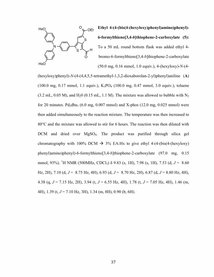
Ethyl 4-(4-(bis(4-(hexyloxy)phenyl)amino)phenyl)-
6-formylthieno[3,4-b]thiophene-2-carboxylate (5):
To a 50 mL round bottom flask was added ethyl 4-
bromo-6-formylthieno[3,4-b]thiophene-2-carboxylate
(50.0 mg, 0.16 mmol, 1.0 equiv.), 4-(hexyloxy)-N-(4-
(hexyloxy)phenyl)-N-(4-(4,4,5,5-tetramethyl-1,3,2-dioxaborolan-2-yl)phenyl)aniline (A)
(100.0 mg, 0.17 mmol, 1.1 equiv.), K3PO4 (100.0 mg, 0.47 mmol, 3.0 equiv.), toluene
(3.2 mL, 0.05 M), and H20 (0.15 mL, 1.1 M). The mixture was allowed to bubble with N2
for 20 minutes. Pd2dba3 (6.0 mg, 0.007 mmol) and X-phos (12.0 mg, 0.025 mmol) were
then added simultaneously to the reaction mixture. The temperature was then increased to
80°C and the mixture was allowed to stir for 6 hours. The reaction was then diluted with
DCM and dried over MgSO4. The product was purified through silica gel
chromatography with 100% DCM à 3% EA:Hx to give ethyl 4-(4-(bis(4-(hexyloxy)
phenyl)amino)phenyl)-6-formylthieno[3,4-b]thiophene-2-carboxylate (97.0 mg, 0.15
mmol, 93%). 1H NMR (500MHz, CDCl3) δ 9.83 (s, 1H), 7.98 (s, 1H), 7.53 (d, J = 8.60
Hz, 2H), 7.10 (d, J = 8.75 Hz, 4H), 6.93 (d, J = 8.70 Hz, 2H), 6.87 (d, J = 8.80 Hz, 4H),
4.38 (q, J = 7.15 Hz, 2H), 3.94 (t, J = 6.55 Hz, 4H), 1.78 (t, J = 7.05 Hz, 4H), 1.46 (m,
4H), 1.39 (t, J = 7.10 Hz, 3H), 1.34 (m, 8H), 0.90 (b, 6H).
S
S
O OEt
H
O
N
HxO
HxO
Page 43
38
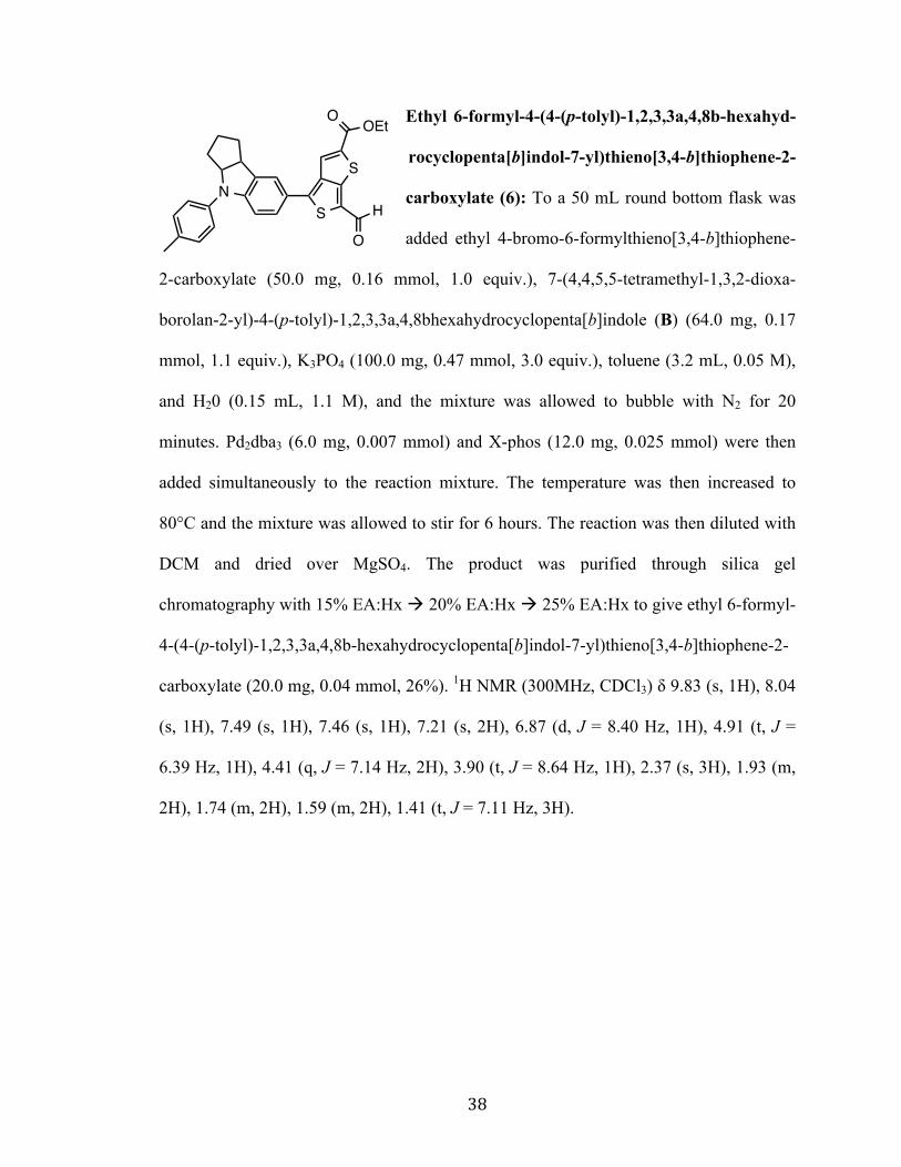
Ethyl 6-formyl-4-(4-(p-tolyl)-1,2,3,3a,4,8b-hexahyd-
rocyclopenta[b]indol-7-yl)thieno[3,4-b]thiophene-2-
carboxylate (6): To a 50 mL round bottom flask was
added ethyl 4-bromo-6-formylthieno[3,4-b]thiophene-
2-carboxylate (50.0 mg, 0.16 mmol, 1.0 equiv.), 7-(4,4,5,5-tetramethyl-1,3,2-dioxa-
borolan-2-yl)-4-(p-tolyl)-1,2,3,3a,4,8bhexahydrocyclopenta[b]indole (B) (64.0 mg, 0.17
mmol, 1.1 equiv.), K3PO4 (100.0 mg, 0.47 mmol, 3.0 equiv.), toluene (3.2 mL, 0.05 M),
and H20 (0.15 mL, 1.1 M), and the mixture was allowed to bubble with N2 for 20
minutes. Pd2dba3 (6.0 mg, 0.007 mmol) and X-phos (12.0 mg, 0.025 mmol) were then
added simultaneously to the reaction mixture. The temperature was then increased to
80°C and the mixture was allowed to stir for 6 hours. The reaction was then diluted with
DCM and dried over MgSO4. The product was purified through silica gel
chromatography with 15% EA:Hx à 20% EA:Hx à 25% EA:Hx to give ethyl 6-formyl-
4-(4-(p-tolyl)-1,2,3,3a,4,8b-hexahydrocyclopenta[b]indol-7-yl)thieno[3,4-b]thiophene-2-
carboxylate (20.0 mg, 0.04 mmol, 26%). 1H NMR (300MHz, CDCl3) δ 9.83 (s, 1H), 8.04
(s, 1H), 7.49 (s, 1H), 7.46 (s, 1H), 7.21 (s, 2H), 6.87 (d, J = 8.40 Hz, 1H), 4.91 (t, J =
6.39 Hz, 1H), 4.41 (q, J = 7.14 Hz, 2H), 3.90 (t, J = 8.64 Hz, 1H), 2.37 (s, 3H), 1.93 (m,
2H), 1.74 (m, 2H), 1.59 (m, 2H), 1.41 (t, J = 7.11 Hz, 3H).
S
S
O OEt
HN
O
Page 44
39
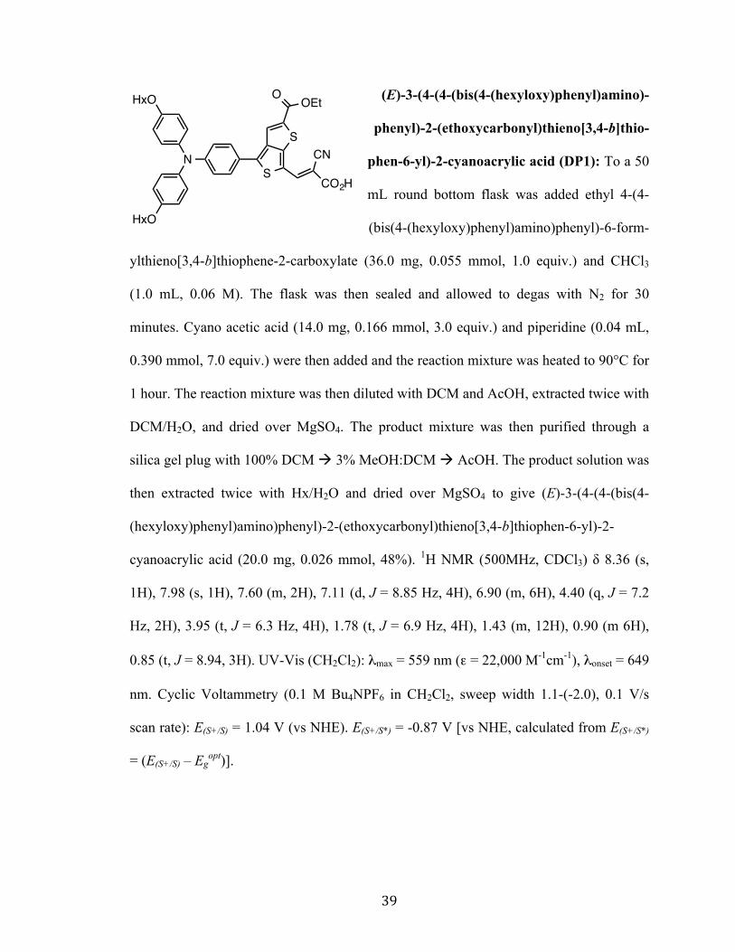
(E)-3-(4-(4-(bis(4-(hexyloxy)phenyl)amino)-
phenyl)-2-(ethoxycarbonyl)thieno[3,4-b]thio-
phen-6-yl)-2-cyanoacrylic acid (DP1): To a 50
mL round bottom flask was added ethyl 4-(4-
(bis(4-(hexyloxy)phenyl)amino)phenyl)-6-form-
ylthieno[3,4-b]thiophene-2-carboxylate (36.0 mg, 0.055 mmol, 1.0 equiv.) and CHCl3
(1.0 mL, 0.06 M). The flask was then sealed and allowed to degas with N2 for 30
minutes. Cyano acetic acid (14.0 mg, 0.166 mmol, 3.0 equiv.) and piperidine (0.04 mL,
0.390 mmol, 7.0 equiv.) were then added and the reaction mixture was heated to 90°C for
1 hour. The reaction mixture was then diluted with DCM and AcOH, extracted twice with
DCM/H2O, and dried over MgSO4. The product mixture was then purified through a
silica gel plug with 100% DCM à 3% MeOH:DCM à AcOH. The product solution was
then extracted twice with Hx/H2O and dried over MgSO4 to give (E)-3-(4-(4-(bis(4-
(hexyloxy)phenyl)amino)phenyl)-2-(ethoxycarbonyl)thieno[3,4-b]thiophen-6-yl)-2-
cyanoacrylic acid (20.0 mg, 0.026 mmol, 48%). 1H NMR (500MHz, CDCl3) δ 8.36 (s,
1H), 7.98 (s, 1H), 7.60 (m, 2H), 7.11 (d, J = 8.85 Hz, 4H), 6.90 (m, 6H), 4.40 (q, J = 7.2
Hz, 2H), 3.95 (t, J = 6.3 Hz, 4H), 1.78 (t, J = 6.9 Hz, 4H), 1.43 (m, 12H), 0.90 (m 6H),
0.85 (t, J = 8.94, 3H). UV-Vis (CH2Cl2): λmax = 559 nm (ε = 22,000 M-1cm-1), λonset = 649
nm. Cyclic Voltammetry (0.1 M Bu4NPF6 in CH2Cl2, sweep width 1.1-(-2.0), 0.1 V/s
scan rate): E(S+/S) = 1.04 V (vs NHE). E(S+/S*) = -0.87 V [vs NHE, calculated from E(S+/S*)
= (E(S+/S) – Egopt)].
S
S
O OEt
N
HxO
HxO
CO2H
CN
Page 45
40
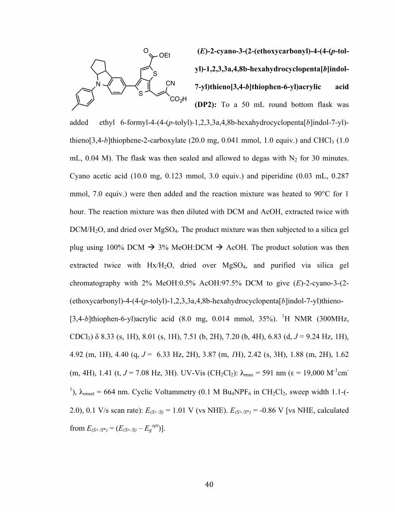
(E)-2-cyano-3-(2-(ethoxycarbonyl)-4-(4-(p-tol-
yl)-1,2,3,3a,4,8b-hexahydrocyclopenta[b]indol-
7-yl)thieno[3,4-b]thiophen-6-yl)acrylic acid
(DP2): To a 50 mL round bottom flask was
added ethyl 6-formyl-4-(4-(p-tolyl)-1,2,3,3a,4,8b-hexahydrocyclopenta[b]indol-7-yl)-
thieno[3,4-b]thiophene-2-carboxylate (20.0 mg, 0.041 mmol, 1.0 equiv.) and CHCl3 (1.0
mL, 0.04 M). The flask was then sealed and allowed to degas with N2 for 30 minutes.
Cyano acetic acid (10.0 mg, 0.123 mmol, 3.0 equiv.) and piperidine (0.03 mL, 0.287
mmol, 7.0 equiv.) were then added and the reaction mixture was heated to 90°C for 1
hour. The reaction mixture was then diluted with DCM and AcOH, extracted twice with
DCM/H2O, and dried over MgSO4. The product mixture was then subjected to a silica gel
plug using 100% DCM à 3% MeOH:DCM à AcOH. The product solution was then
extracted twice with Hx/H2O, dried over MgSO4, and purified via silica gel
chromatography with 2% MeOH:0.5% AcOH:97.5% DCM to give (E)-2-cyano-3-(2-
(ethoxycarbonyl)-4-(4-(p-tolyl)-1,2,3,3a,4,8b-hexahydrocyclopenta[b]indol-7-yl)thieno-
[3,4-b]thiophen-6-yl)acrylic acid (8.0 mg, 0.014 mmol, 35%). 1H NMR (300MHz,
CDCl3) δ 8.33 (s, 1H), 8.01 (s, 1H), 7.51 (b, 2H), 7.20 (b, 4H), 6.83 (d, J = 9.24 Hz, 1H),
4.92 (m, 1H), 4.40 (q, J = 6.33 Hz, 2H), 3.87 (m, 1H), 2.42 (s, 3H), 1.88 (m, 2H), 1.62
(m, 4H), 1.41 (t, J = 7.08 Hz, 3H). UV-Vis (CH2Cl2): λmax = 591 nm (ε = 19,000 M-1cm-
1), λonset = 664 nm. Cyclic Voltammetry (0.1 M Bu4NPF6 in CH2Cl2, sweep width 1.1-(-
2.0), 0.1 V/s scan rate): E(S+/S) = 1.01 V (vs NHE). E(S+/S*) = -0.86 V [vs NHE, calculated
from E(S+/S*) = (E(S+/S) – Egopt)].
S
S
O OEt
N
CO2H
CN
Page 46
41
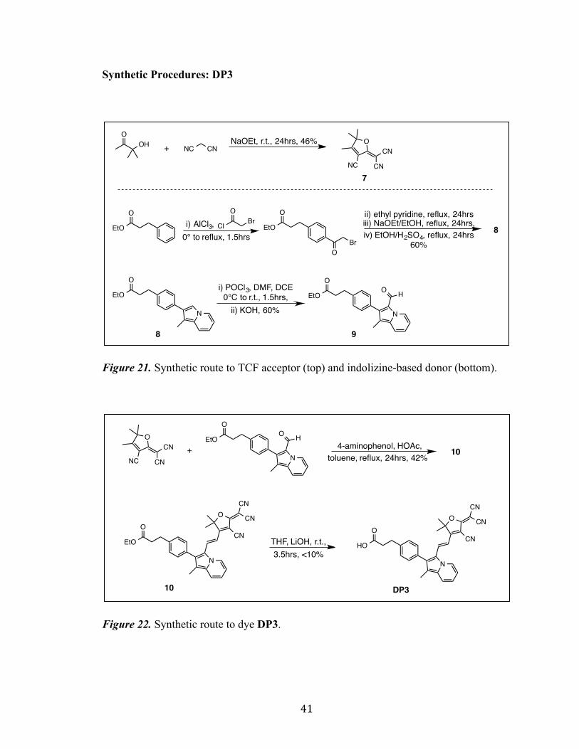
Synthetic Procedures: DP3
Figure 21. Synthetic route to TCF acceptor (top) and indolizine-based donor (bottom).
Figure 22. Synthetic route to dye DP3.
O
NC
CN
CN
NC CNOHO
NaOEt, r.t., 24hrs, 46%+
7
N
EtO
O
N
EtO
O
HO
EtO
O
Cl BrO
EtO
O
BrO
ii) ethyl pyridine, reflux, 24hrsiii) NaOEt/EtOH, reflux, 24hrs,
i) POCl3, DMF, DCE0°C to r.t., 1.5hrs,
i) AlCl3,
8 9
8iv) EtOH/H2SO4, reflux, 24hrs60%
0° to reflux, 1.5hrs
ii) KOH, 60%
N
HO
OO
CN
CN
CN
N
EtO
OO
CN
CN
CN
O
NC
CN
CN N
EtO
O
HO
+ 4-aminophenol, HOAc,
THF, LiOH, r.t.,
10 DP3
10toluene, reflux, 24hrs, 42%
3.5hrs, <10%
Page 47
42
2-(3-cyano-4,5,5-trimethylfuran-2(5H)-ylidene)malononitrile (7):[27]
To a 100 mL round bottom flask was added 3,3-dimethyl-3-hydroxy
propanone (1.68 g, 16.4 mmol, 1.0 equiv.), malononitrile (2.71 g, 41.0
mmol, 2.5 equiv.), and NaOEt (16.5 mL, 1.2 M). The reaction mixture was then allowed
to stir at room temperature for 24 hours. The product mixture was then concentrated
followed by acidified using 6.0 M aqueous HCl to ~ pH 4-5. The crude product was then
filtered off and recrystallized from EtOH to give pure 2-(3-cyano-4,5,5-trimethyl-furan-
2(5H)-ylidene)malononitrile (1.5 g, 46%). 1H NMR (300MHz, CDCl3) δ 2.35 (s, 3H),
1.62 (s, 6H).
Ethyl 3-(4-(1-methylindolizin-2-yl)phenyl)propan-
oate (8):[28] To a flame dried, N2 filled 100 mL round
bottom flask was added ethyl 3-phenyl propanoate (3.0
mL, 16.8 mmol, 1.0 equiv) and DCM (9.5 mL, 1.8 M). The flask was then cooled to -5°C
and bromoacetyl chloride (2.2 mL, 27.1 mmol, 1.6 equiv.) and AlCl3 (6.1 g, 45.6 mmol,
2.7 equiv.) were added. The reaction mixture was allowed to stir at 0°C for 30 minutes
and then subjected to reflux for 1 hour. The mixture was then poured onto ice water,
extracted with DCM, dried over MgSO4, and filtered to give the intermediate ethyl 3-(4-
(2-bromoacetyl)phenyl)propanoate. To a 150 mL round bottom flask was then added
ethyl 3-(4-(2-bromoacetyl)phenyl)propanoate (6.1 g, 23.9 mmol, 1.0 equiv.) and ethyl
pyridine (2.7 mL, 23.9 mmol, 1.0 equiv.) in an acetone solution (12.0 mL, 2.0 M). This
mixture was allowed to reflux for 24 hours. Acetone was then removed from the reaction
mixture, followed by the addition of 21% NaOEt:EtOH (35.0 mL, 95.6 mmol, 4.0
O
NC
CN
CN
N
EtO
O
Page 48
43
equiv.). This mixture was then again allowed to reflux for 24 hours. The product obtained
at this point was noted to be completely water soluble and it was hypothesized that the
ester chain α position had been deprotonated. The product mixture was then transferred to
a 1 L flask using H2O (500.0 mL) and the pH of the solution was adjusted to pH 5-6
using AcOH. The product mixture was then extracted using DCM/H2O. NMR analysis
showed presence of acid product due to ester chain hydrolysis. The acid product, EtOH
(300.0 mL), and H2SO4 (2.0 mL) were then added to a 1 L round bottom flask and
allowed to reflux for 24 hours. The product mixture was then extracted with DCM/H2O
and dried over MgSO4 to give pure ethyl 3-(4-(1-methylindolizin-2-yl)phenyl)propanoate
(3.1g, 10.1 mmol, 60%). 1H NMR (300MHz, CDCl3) δ 7.84 (d, J = 6.93 Hz, 1H), 7.44 (d,
J = 8.01 Hz, 2H), 7.36 (s, 1H), 7.32 (b, 1H), 7.29 (b, 2H), 6.60 (t, J = 7.02 Hz, 1H), 6.40
(t, J = 6.21 Hz, 1H), 4.15 (q, J = 7.11 Hz, 2H), 2.99 (t, J = 7.41 Hz, 2H), 2.66 (t, J = 8.16
Hz, 2H), 2.41 (s, 3H), 1.21 ( t, J = 5.88 Hz, 3H).
Ethyl 3-(4-(3-formyl-1-methylindolizin-2-yl)phenyl)-
propanoate (9): To a 50 mL round bottom flask was
added ethyl 3-(4-(1-methylindolizin-2-yl)phenyl)prop-
anoate (1.0 g, 3.25 mmol, 1.0 equiv.). The flask was then subjected to an N2/vacuum
cycle followed by the addition of DCE (8.1 mL, 0.4 M) and anhydrous DMF (0.28 mL,
3.58 mmol, 1.1 equiv.). The flask was then cooled to 0°C and POCl3 (0.33 mL, 3.58
mmol, 1.1 equiv.) was added dropwise by syringe. The reaction was then allowed to
warm to room temperature and stir for 1.5 hours. The product mixture was extracted with
excess DCM/KOH. Purification was obtained via silica gel chromatography with 100%
N
EtO
O
HO
Page 49
44
DCM à 20% EA:DCM to give ethyl 3-(4-(3-formyl-1-methylindolizin-2-yl)phenyl)-
propanoate (640.0 mg, 1.95 mmol, 60%). 1H NMR (300MHz, CDCl3) δ 9.81 (d, J = 6.96
Hz, 1H), 9.51 (s, 1H), 7.52 (d, J = 8.91 Hz, 2H), 7.30 (d, J = 8.16 Hz, 2H), 7.21 (t, 1H),
6.91 (t, J = 7.08 Hz, 1H), 4.13 (q, J = 7.14 Hz, 2H), 3.03 (t, J = 7.5 Hz, 2H), 2.68 (t, J =
8.19 Hz, 2H), 2.26 (s, 3H), 1.25 (t, J = 7.11 Hz, 3H).
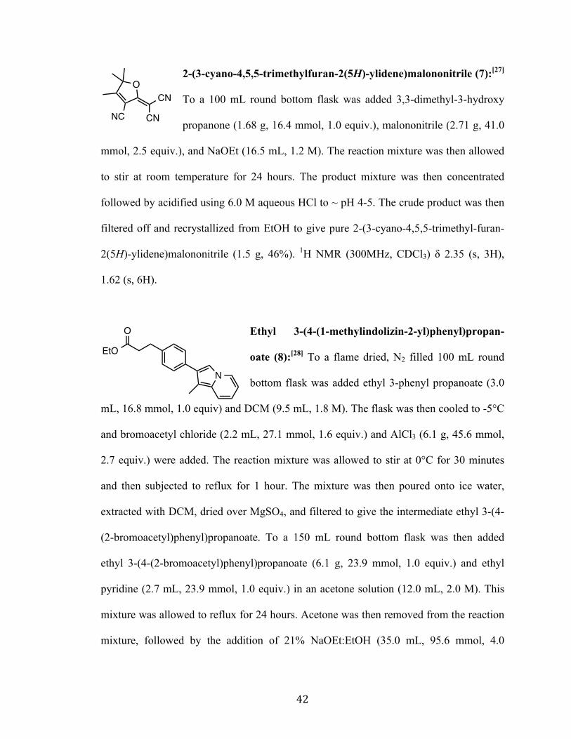
Ethyl (E)-3-(4-(3-(2-(4-cyano-5-(dicyano-
methylene)-2,2-dimethyl-2,5-dihydrofuran-3-
yl)vinyl)-1-methylindolizin-2-yl)phenyl)prop-
anoate (10): To a flame dried, N2 filled round
bottom flask was added ethyl 3-(4-(3-formyl-1-
methylindolizin-2-yl)phenyl) propanoate (77.0 mg, 0.23 mmol, 1.0 equiv), 2-(3-cyano-
4,5,5-trimethylfuran-2(5H)-ylidene)malononitrile (50.0 mg, 0.25 mmol, 1.1 equiv.), 4-
aminophenol (10.9 mg, 0.10 mmol, 0.4 equiv.), AcOH (0.03 mL), and toluene (5.0 mL).
The reaction mixture was then heated to 120°C and allowed to reflux under dean-stark
setup for 24 hours. The product mixture was extracted using excess DCM/H2O, and then
dried over Na2SO4. Purification was achieved using silica gel chromatography with 100%
DCM à 3% EA:DCM à 5% EA:DCM à 10% EA:DCM to give ethyl (E)-3-(4-(3-(2-
(4-cyano-5-(dicyanomethylene)-2,2-dimethyl-2,5-dihydrofuran-3-yl)vinyl)-1-
methylindolizin-2-yl)phenyl)propanoate (50.0 mg, 0.01 mmol, 42% yield). 1H NMR
(300MHz, CDCl3) δ 8.42 (d, J = 7.29 Hz, 1H), 7.55 (d, J = 8.19 Hz, 1H), 7.39 (s, 2H),
7.36 (s, 2H), 7.09 (t, J = 5.91 Hz, 2H), 4.13 (q, J = 7.05 Hz, 2H), 3.05 (t, J = 7.98 Hz,
2H), 2.68 (t, J = 7.71 Hz, 2H), 2.19 (s, 3H), 2.01 (s, 6H), 0.84 (t, J = 8.13 Hz, 3H). UV-
N
EtO
OO
CN
CN
CN
Page 50
45
Vis (CH2Cl2): λmax = 638 nm (ε = 57,000 M-1cm-1), λonset = 664 nm. Cyclic Voltammetry
(0.1 M Bu4NPF6 in CH2Cl2, sweep width 1.1-(-2.0), 0.1 V/s scan rate): E(S+/S) = 1.22 V
(vs NHE). E(S+/S*) = -0.65 V [vs NHE, calculated from E(S+/S*) = (E(S+/S) – Egopt)].
(E)-3-(4-(3-(2-(4-cyano-5-(dicyanomethylene)
-2,2-dimethyl-2,5-dihydrofuran-3-yl) vinyl)1-
methylindolizin-2-yl)phenyl)propanoic acid
(DP3): To a 50 mL round bottom flask was
added ethyl (E)-3-(4-(3-(2-(4-cyano-5-(dicyano-
methylene)-2,2-dimethyl-2,5-dihydrofuran-3-yl)vinyl)-1-methylindolizin-2-yl)phenyl)-
propanoate (38.0 mg, 0.74 mmol, 1.0 equiv.), LiOH (5.0 ml), and THF (5.0 mL). The
reaction mixture was allowed to stir at room temperature for 3.5 hours. Next, the reaction
mixture was diluted with 5% AcOH:DCM (100.0 mL), and washed 3 times with excess
H2O. Product purification was attempted via an alumina plug with 100% DCM à 5%
MeOH:DCM à 10% MeOH:DCM à 20% MeOH:DCM à 50% MeOH:DCM à 100%
MeOH à 3% AcOH:MeOH. The product mixture was then extracted with excess
DCM/H2O, and dried over Na2SO4. NMR analysis showed product decomposition along
with the presence of the desired product, (E)-3-(4-(3-(2-(4-cyano-5-(dicyanomethylene)-
2,2-dimethyl-2,5-dihydrofuran-3-yl)vinyl)-1-methylindolizin-2-yl)phenyl)propanoic acid
(<10%). UV-Vis spectrum and cyclic voltammetry measurements for DP3 were
approximated using compound 10, ethyl (E)-3-(4-(3-(2-(4-cyano-5-(dicyanomethylene)-
2,2-dimethyl-2,5-dihydrofuran-3-yl)vinyl)-1-methylindolizin-2-yl)phenyl)propanoate. 1H
NMR (300MHz, CDCl3) δ 8.43 (d, J = 6.33 Hz, 1H), 7.55 (m, 1H), 7.38 (m, 4H), 7.19
N
HO
OO
CN
CN
CN
Page 51
46
(m, 1H), 7.11 (m, 1H), 3.06 (t, J = 6.9 Hz, 2H), 2.74 (t, J = 7.14 Hz, 2H), 2.26 (s, 3H),
2.19 (s, 6H).
Computational Details
All computations were performed with the Gaussian09[21] software package. The
geometry optimization for dyes DP1 and DP2 were as follows: first the structures were
optimized by MM2 in the ChemBio3D (version: 13.0.2.3021) software package and
dihedral angles for all relevant groups set to values in-between the global minimum and
the next local maximum on the conformational energy diagram as calculated by
ChemBio3D (version: 13.0.2.3021) in the dihedral driver toolset. After MM2
optimization, the molecular structures were further optimized by DFT methods: first
B3LYP/3-21G[22,23] and then B3LYP/6-311G(d,p)[22,23]. Lastly, time-dependent density
functional theory (TD-DFT) computations were carried out to compute the vertical
transition energies and oscillator strengths for the 10 lowest excited states. Symmetry
was explicitly turned off for these computations even though all of the optimized
structures belonged to the C1 point group. A representative TD-DFT input file is included
for both DP1 and DP2.
Photovoltaic Characterization
A 450W xenon lamp (Oriel, USA) was used as a light source to study the current-
voltage characteristics of the DSSC. The spectral output of the lamp was filtered using a
Schott K113 Tempax sunlight filter (Präzisions Glas & Optik GmbH, Germany) to
reduce the mismatch between the simulated and actual solar spectrum to less than 2 %.
Page 52
47
The Keithley model 2400 digital source meter (Keithley, USA) was used for data
acquisition. The photo-active area of 0.16 cm2 was defined by a black mask of 6x6 mm2.
Incident photon-to-current conversion efficiency measurements were carried from the
mono chromated visible photons, from Gemini-180 double monochromator Jobin Yvon
Ltd. (UK), powered by a 300 W xenon light source (ILC Technology, USA)
superimposed on a 10mW/cm2 LED light. The monochromatic incident light was passed
through a chopper running at 2 Hz frequency and the on / off ratio was measured by an
operational amplifier.
Device Fabrication
The photoanode consists of thin TiO2 electrodes comprising a 9.5 mm
mesoporous TiO2 layer (particle size, 20 nm) and a 5.0 mm TiO2 scattering layer (particle
size, 400 nm). The working electrode was prepared by immersing the 14.5 mm (9.5 mm
thick transparent layer + 5.0 mm thick scattering) TiO2 film into the dye solution for 18
h. A thermally platinized FTO glass counter electrode and the working electrode were
then sealed with a 25 mm thick hot-melt film (Surlyn, Dupont) by heating the system at
100°C. Devices were completed by filling the electrolyte by pre-drilled holes in the
counter electrodes and finally the holes were sealed with a Surlyn sheet and a thin glass
cover by heating. A black mask (6x6 mm2) was used in the subsequent photovoltaic
studies.
Page 53
48
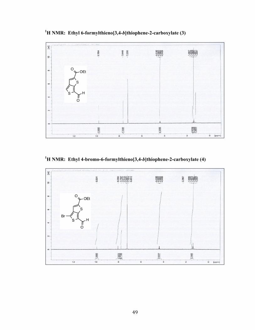
1H NMR Data.
1H NMR: 4-bromothiophene-3-carbaldehyde (1)
1H NMR: Ethyl thieno[3,4-b]thiophene-2-carboxylate (2)
S
BrH
O
Page 54
49
1H NMR: Ethyl 6-formylthieno[3,4-b]thiophene-2-carboxylate (3)
1H NMR: Ethyl 4-bromo-6-formylthieno[3,4-b]thiophene-2-carboxylate (4)
Page 55
50
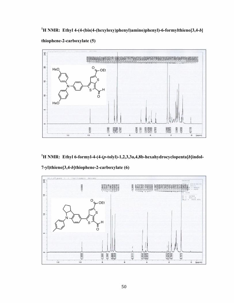
1H NMR: Ethyl 4-(4-(bis(4-(hexyloxy)phenyl)amino)phenyl)-6-formylthieno[3,4-b]
thiophene-2-carboxylate (5)
1H NMR: Ethyl 6-formyl-4-(4-(p-tolyl)-1,2,3,3a,4,8b-hexahydrocyclopenta[b]indol-
7-yl)thieno[3,4-b]thiophene-2-carboxylate (6)
Page 56
51
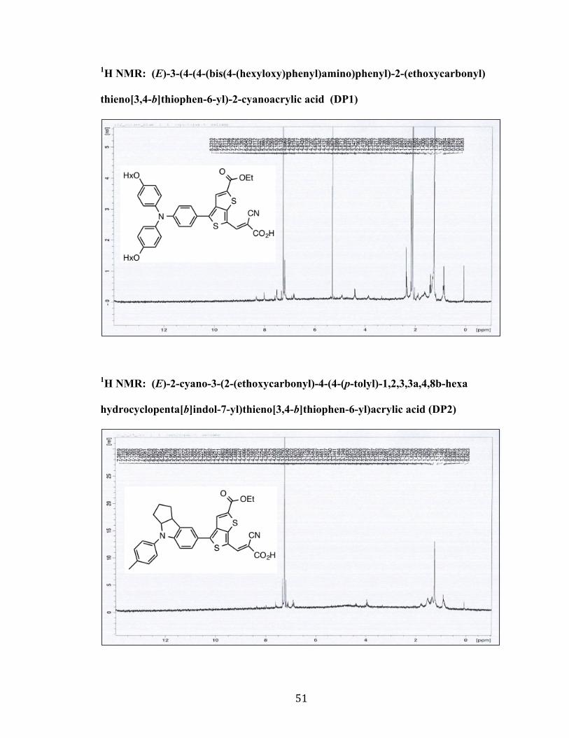
1H NMR: (E)-3-(4-(4-(bis(4-(hexyloxy)phenyl)amino)phenyl)-2-(ethoxycarbonyl)
thieno[3,4-b]thiophen-6-yl)-2-cyanoacrylic acid (DP1)
1H NMR: (E)-2-cyano-3-(2-(ethoxycarbonyl)-4-(4-(p-tolyl)-1,2,3,3a,4,8b-hexa
hydrocyclopenta[b]indol-7-yl)thieno[3,4-b]thiophen-6-yl)acrylic acid (DP2)
Page 57
52
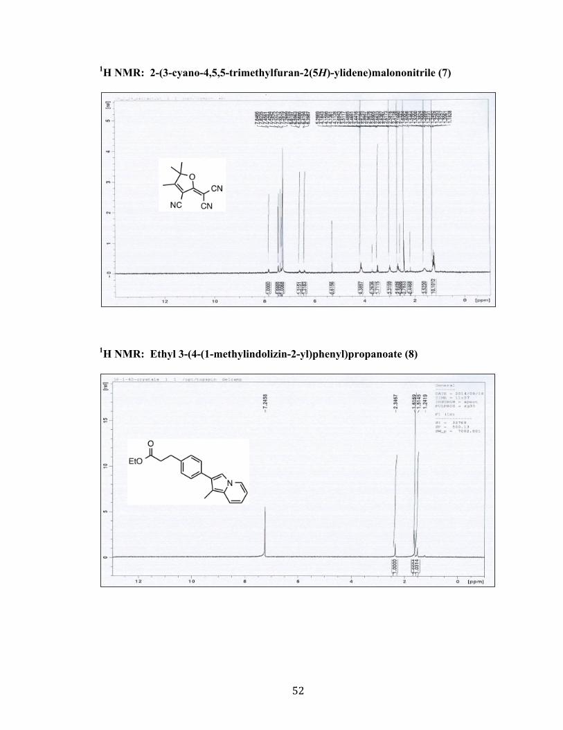
1H NMR: 2-(3-cyano-4,5,5-trimethylfuran-2(5H)-ylidene)malononitrile (7)
1H NMR: Ethyl 3-(4-(1-methylindolizin-2-yl)phenyl)propanoate (8)
Page 58
53
1H NMR: Ethyl 3-(4-(3-formyl-1-methylindolizin-2-yl)phenyl)propanoate (9)
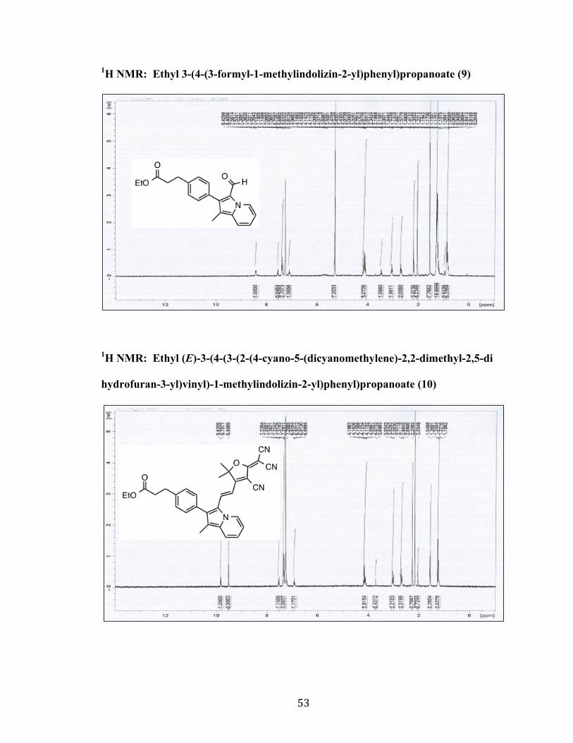
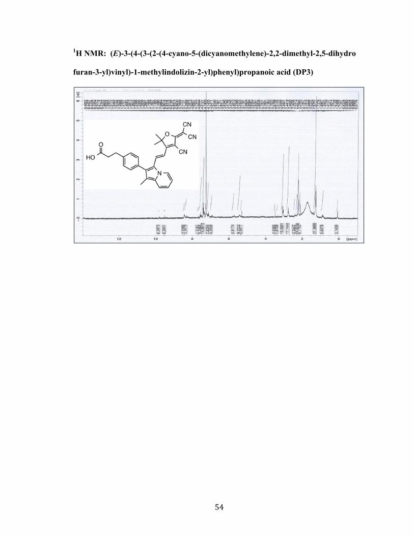
1H NMR: Ethyl (E)-3-(4-(3-(2-(4-cyano-5-(dicyanomethylene)-2,2-dimethyl-2,5-di
hydrofuran-3-yl)vinyl)-1-methylindolizin-2-yl)phenyl)propanoate (10)
Page 59
54
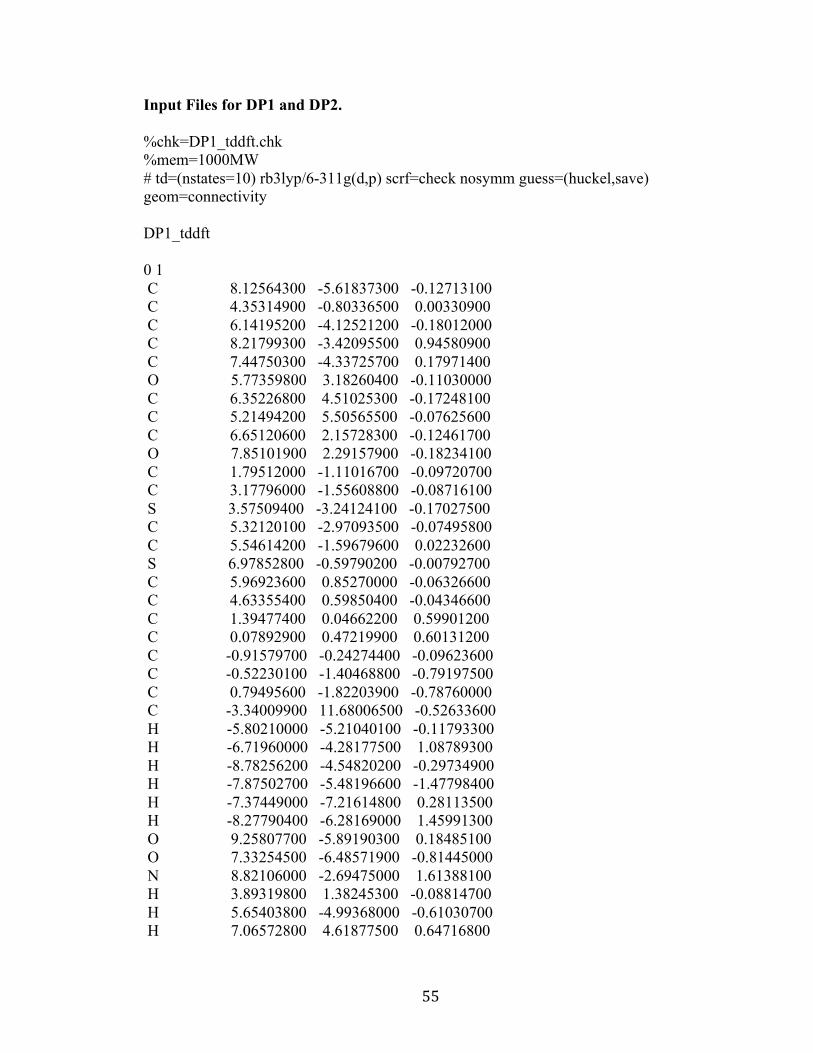
1H NMR: (E)-3-(4-(3-(2-(4-cyano-5-(dicyanomethylene)-2,2-dimethyl-2,5-dihydro
furan-3-yl)vinyl)-1-methylindolizin-2-yl)phenyl)propanoic acid (DP3)
Page 60
55
Input Files for DP1 and DP2.
%chk=DP1_tddft.chk %mem=1000MW # td=(nstates=10) rb3lyp/6-311g(d,p) scrf=check nosymm guess=(huckel,save) geom=connectivity DP1_tddft 0 1 C 8.12564300 -5.61837300 -0.12713100 C 4.35314900 -0.80336500 0.00330900 C 6.14195200 -4.12521200 -0.18012000 C 8.21799300 -3.42095500 0.94580900 C 7.44750300 -4.33725700 0.17971400 O 5.77359800 3.18260400 -0.11030000 C 6.35226800 4.51025300 -0.17248100 C 5.21494200 5.50565500 -0.07625600 C 6.65120600 2.15728300 -0.12461700 O 7.85101900 2.29157900 -0.18234100 C 1.79512000 -1.11016700 -0.09720700 C 3.17796000 -1.55608800 -0.08716100 S 3.57509400 -3.24124100 -0.17027500 C 5.32120100 -2.97093500 -0.07495800 C 5.54614200 -1.59679600 0.02232600 S 6.97852800 -0.59790200 -0.00792700 C 5.96923600 0.85270000 -0.06326600 C 4.63355400 0.59850400 -0.04346600 C 1.39477400 0.04662200 0.59901200 C 0.07892900 0.47219900 0.60131200 C -0.91579700 -0.24274400 -0.09623600 C -0.52230100 -1.40468800 -0.79197500 C 0.79495600 -1.82203900 -0.78760000 C -3.34009900 11.68006500 -0.52633600 H -5.80210000 -5.21040100 -0.11793300 H -6.71960000 -4.28177500 1.08789300 H -8.78256200 -4.54820200 -0.29734900 H -7.87502700 -5.48196600 -1.47798400 H -7.37449000 -7.21614800 0.28113500 H -8.27790400 -6.28169000 1.45991300 O 9.25807700 -5.89190300 0.18485100 O 7.33254500 -6.48571900 -0.81445000 N 8.82106000 -2.69475000 1.61388100 H 3.89319800 1.38245300 -0.08814700 H 5.65403800 -4.99368000 -0.61030700 H 7.06572800 4.61877500 0.64716800
Page 61
56
H 6.90524800 4.60628300 -1.10987400 H 5.61043500 6.52373500 -0.11971600 H 4.51047000 5.37539700 -0.90078900 H 4.67318600 5.38760500 0.86470800 H 2.11931100 0.59097500 1.19178600 H -0.19635700 1.35249700 1.16708500 H 1.06565100 -2.69981800 -1.36413600 H 7.86800800 -7.28076200 -0.94596300 H -9.45435100 -7.49314200 -1.09524600 H -9.84474300 -8.26427400 1.84248900 H -1.25932600 -1.96589200 -1.35104400 C -6.66981000 -4.55338700 0.02548300 O -6.51947200 -3.37312500 -0.76748600 C -8.22110100 -6.52649600 0.39157000 C -7.94911900 -5.24932500 -0.41059100 C -9.51012200 -7.24243100 -0.02831200 H -10.35760800 -6.55329300 0.07798700 C -9.79066700 -8.51618200 0.77647600 H -8.94343800 -9.20442300 0.66980000 C -11.08016600 -9.22598500 0.35426100 H -11.24977300 -10.13008900 0.94502500 H -11.95080600 -8.57585800 0.48508200 H -11.04320200 -9.51995800 -0.69931300 N -2.24679300 0.18116800 -0.09500700 C -4.32746000 -0.51962400 -1.19924800 C -5.38117500 -1.40745300 -1.33909700 H -4.28319200 0.36871200 -1.81798100 H -6.16719900 -1.23300200 -2.06366000 C -3.31763600 -0.75301200 -0.25561100 C -3.39524100 -1.89684700 0.53893000 H -2.62742300 -2.08506200 1.28007500 C -5.44827900 -2.56286400 -0.54888400 C -4.44200900 -2.80534300 0.39123500 H -4.46790200 -3.68323300 1.02205000 C -2.33923200 3.89569600 -0.50252200 C -2.01701200 2.55278600 -0.69308700 H -1.88316100 4.64141700 -1.13910500 H -1.31529400 2.27773000 -1.47176000 C -2.57959900 1.55763000 0.10598100 C -3.49657000 1.92937800 1.09854300 H -3.94585100 1.16541700 1.72171900 C -3.83541300 3.25929200 1.28325400 C -3.25624000 4.25815200 0.48895500 H -4.54351600 3.55548200 2.04749300 C -3.11881200 6.60475200 -0.02670600 H -2.02423200 6.61996700 0.05532200
Page 62
57
H -3.37978600 6.45549900 -1.08252700 C -3.71471000 7.90090000 0.49850300 H -4.80601000 7.82822200 0.44659400 H -3.45526300 7.99898700 1.55782300 C -3.23069000 9.12965400 -0.27951000 H -2.13483400 9.17864100 -0.24372100 H -3.49721400 9.02070700 -1.33857200 C -3.80935900 10.44583900 0.25213800 H -4.90531300 10.39633600 0.22494500 H -3.53661400 10.55967500 1.30904200 H -2.24456700 11.72618200 -0.50319600 H -3.61718400 11.56784900 -1.58154100 C -3.91666000 12.99099300 0.01570100 H -3.56491500 13.85034800 -0.56133200 H -5.01031300 12.98899600 -0.02487100 H -3.62535900 13.14978700 1.05862000 O -3.64879000 5.53302200 0.75730100 %chk=DP2_tddft.chk %mem=1000MW # td=(nstates=10) rb3lyp/6-311g(d,p) scrf=check nosymm guess=(huckel,save) geom=connectivity DP2_tddft 0 1 C 1.94820700 0.40380300 0.03672400 O 1.96316000 4.61958500 -0.38050900 C 7.14888600 -2.84158700 0.08513800 C -5.27823000 -3.45558400 0.32344400 H -9.70344200 2.44528700 0.55521000 H 0.78493800 2.30175300 -0.16712800 H -6.15784600 3.26553600 -0.31636600 C 0.66347900 6.61685500 -0.56855800 C 6.04929400 -1.85070500 0.31573300 H 4.57880700 -3.12180800 -0.43276600 C -4.65720400 -4.72821200 -0.26930600 H -7.01692600 -1.44532800 0.88517900 C 6.40902300 -0.72695000 1.10673200 H -0.57733100 1.01690400 1.26534100 H -3.02666700 0.99353900 1.29959300 H -8.66391200 3.66936600 -0.18344300 H -8.62398000 3.41250800 1.55961600 C -6.35283200 2.23352100 -0.04188700 C 4.75494100 -2.11884700 -0.04956600
Page 63
58
C -7.62326800 1.87296800 0.41980100 N -4.53611500 -1.01668000 -0.00882500 C -3.23863800 -4.28584900 -0.66757400 C 3.12986600 3.94399500 -0.34396200 C 2.06998800 6.05615200 -0.54958800 C -1.10267000 0.24701400 0.71422500 C -6.82096000 -0.41766900 0.61018900 C -8.71248000 2.90269700 0.59388100 C 1.09139100 -0.70052300 0.02542000 C 3.58404300 -1.31695300 0.03485100 C 3.33785700 0.05535200 0.05876200 C -7.83473200 0.52779300 0.73028600 H -8.80949400 0.20850300 1.08490900 S 2.02971900 -2.16124100 0.01850800 C -5.55016300 -0.04668900 0.15309100 C -5.33548600 1.29830800 -0.18415500 H -4.37782400 1.60708200 -0.58295500 C -0.36104000 -0.74227500 0.03990300 C -2.49045100 0.23464800 0.74580800 C -3.17290700 -0.79279600 0.08086000 N 6.68978800 0.17049900 1.78001100 C -2.44756500 -1.81124600 -0.56989800 C -1.07109500 -1.78699400 -0.59613200 H -0.52667900 -2.55917700 -1.12959300 S 4.35541300 1.46805800 -0.07004600 C 2.91904800 2.49460600 -0.18029700 C 1.74506000 1.81335700 -0.10076100 O 8.14259200 -2.89694900 0.75213700 O 6.95160000 -3.72426500 -0.93776400 O 4.21855000 4.46060900 -0.43827400 H 2.66407000 6.46026700 0.27300500 H 2.60719100 6.25832000 -1.47894300 H 0.14354400 6.39874300 0.36686600 H 0.70052700 7.70181900 -0.69561600 H 0.08579400 6.19423100 -1.39354400 C -4.79893300 -2.33475100 -0.62907900 C -3.40392100 -2.82095700 -1.15773800 H -5.51740300 -2.19739600 -1.44121800 H -3.37415300 -2.78308400 -2.25079100 H -6.36576000 -3.51020900 0.40154800 H -4.87841900 -3.27083100 1.32581500 H -4.65942400 -5.56697500 0.42998200 H -5.22041300 -5.04136400 -1.15551800 H -2.79054700 -4.92854300 -1.42786100 H -2.58287900 -4.31004200 0.20741500 H 6.27214700 -3.39161300 -1.53523900