36
mikroC PRO for FT90x Creating the first project in
mikroCPRO for FT90x
Creating the
first project in

page 2
I want to express my thanks to you for being
interested in our products and for having confidence
in MikroElektronika.
The primary aim of our company is to design and
produce high quality electronic products and to
constantly improve the performance thereof in order
to better suit your needs.
TO OUR VALUED CUSTOMERS
Nebojsa Matic
General Manager
page 3
1. Installation . . . . . . . . . . . . . . . . . . . . . . . . . . . . . . . . . . . . . . . . 04
2. Activating compiler license . . . . . . . . . . . . . . . . . . . . . . . . . 05
3. Overview . . . . . . . . . . . . . . . . . . . . . . . . . . . . . . . . . . . . . . . . . 08
4. Hardware Connection . . . . . . . . . . . . . . . . . . . . . . . . . . . . . . 10
5. Creating a New Project . . . . . . . . . . . . . . . . . . . . . . . . . . . . . 12
Step 1 - Project Settings . . . . . . . . . . . . . . . . . . . . . . . . 14
Step2-Addfiles...............................20
Step 3 - Include Libraries . . . . . . . . . . . . . . . . . . . . . . . . 22
Step 4 - Finishing . . . . . . . . . . . . . . . . . . . . . . . . . . . . . . 24
Blank new project created . . . . . . . . . . . . . . . . . . . . . . 26
6. Code Example . . . . . . . . . . . . . . . . . . . . . . . . . . . . . . . . . . . . . 27
7. Building the Source . . . . . . . . . . . . . . . . . . . . . . . . . . . . . . . . 30
8. Changing Project Settings . . . . . . . . . . . . . . . . . . . . . . . . . . 32
9. More examples .. . . . . . . . . . . . . . . . . . . . . . . . . . . . . . . . . . . . 34
Table of Contents
page 4
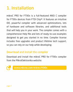
1. Installation
mikroC PRO for FT90x is a full-featured ANSI C compiler
for FT90x devices from FTDI Chip®. It features an intuitive
IDE, powerful compiler with advanced optimizations, lots
of hardware and software libraries, and additional tools
that will help you in your work. The compiler comes with a
comprehensiveHelpfileandlotsofready-to-useexamples
designed to get you started in no time. Compiler license
includes free upgrades and product lifetime tech support,
so you can rely on our help while developing.
Download and install the compiler
Download and install the mikroC PRO for FT90x compiler
from the MikroElektronika website:
www.mikroe.com/mikroc/ft90x
page 5
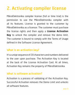
2. Activating compiler license
MikroElektronika compiler license (full or time trial) is the
permission to use the MikroElektronika compiler with
all its features. License is granted to the customer by
MikroElektronika as a licensor. The customer must purchase
the license rights and then apply a License Activation
Key to unlock the compiler and remove the demo limit.
The customer is bound to comply with the Terms of Usage
definedintheSoftwareLicenseAgreement.
What is an activation key?
It’s a uniqe sequence of 20 characters and numbers delivered
to the user upon purchase. The Activation Key is located
at the back of the License Activation Card. At all times,
Activation Key remains the property of MikroElektronika.
What is software activation?
Activation is a process of validating of the Activation Key.
Successful Activation removes the Demo Limit and unlocks
all software features.
page 6
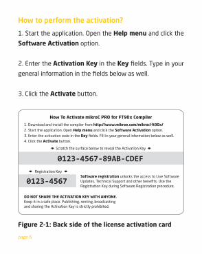
How to perform the activation?
1. Start the application. Open the Help menu and click the
Software Activation option.
2. Enter the Activation Key in the Keyfields.Typeinyour
generalinformationinthefieldsbelowaswell.
3. Click the Activate button.
How To Activate mikroC PRO for FT90x Compiler
1. Download and install the compiler from http://www.mikroe.com/mikroc/ft90x/2. Start the application. Open Help menu and click the Software Activation option.3. Enter the activation code in the Key fields. Fill in your general information below as well. 4. Click the Activate button.
Scratch the surface below to reveal the Activation Key
Software registration unlocks the access to Live Software Updates, Technical Support and other benefits. Use the Registration Key during Software Registration procedure.
DO NOT SHARE THE ACTIVATION KEY WITH ANYONE. Keep it in a safe place. Publishing, renting, broadcasting and sharing the Activation Key is strictly prohibited.
Registration Key
0123-4567-89AB-CDEF
0123-4567
Figure 2-1: Back side of the license activation card
page 7
What is software registration?
Registration is a process which establishes a unique
connection between MikroElektronika as a Licensor and
the customer as a Licensee. By registering a copy of the
Compiler, the customer is granted access to Live Updates,
TechnicalSupportandotherbenefits.
Why should I keep my activation key a secret?
Publishing, renting, public performance, broadcasting or
otherwise disclosing the Activation Key to a third party is
strictly prohibited. By doing so a customer may loose all
benefitsgrantedbyregistration.Incaseofsevereviolations
of Software License Agreement, MikroElektronika reserves
the right to delicense the customer and request the removal
of the Activation Key from the customer’s computer.
page 8
3. Overview
mikroC PRO for FT90x organizes applications into projects
consisting of a single project file (file with the .mcpf9
extension) andoneormore sourcefiles (fileswith the .c
extension). The mikroC PRO for FT90x compiler allows you
tomanage several projects at a time. Sourcefiles canbe
compiled only if they are part of the project.
In this reference guide, we will create a new project, write
code, compile it and test the results. The purpose of this
project is to make two microcontroller LEDs blink, which will
be easy to test.
Aprojectfilecontains:
• Project name and optional description;
• Target device in use;
• Device clock;
•Listoftheprojectsourcefiles;
•Binaryfiles(*.emcl);and
•Otherfiles.
page 9
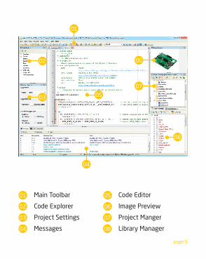
01
04
02
03 07
05
08
06
Main Toolbar
Code Explorer
Project Settings
Messages
Code Editor
Image Preview
Project Manger
Library Manager
01
02
03
04
05
06
07
08
page 10
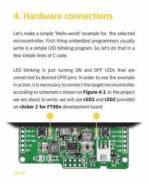
4. Hardware connections
01 02
Let’s make a simple “Hello world” example for the selected
microcontroller. First thing embedded programmers usually
write is a simple LED blinking program. So, let’s do that in a
few simple lines of C code.
LED blinking is just turning ON and OFF LEDs that are
connected to desired GPIO pins. In order to see the example
in action, it is necessary to connect the target microcontroller
according to schematics shown on Figure 4-1. In the project
we are about to write, we will use LED1 and LED2 provided
on clicker 2 for FT90x development board.
page 11
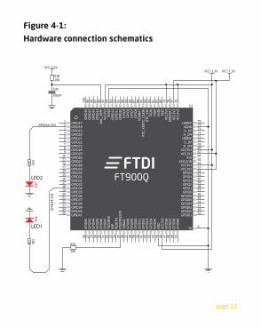
Figure 4-1:
Hardware connection schematicsR1 2K
2R2 2K
2
VCC-3.3V
75747372717069686766
6465
63626160595857565554535251
50494847464544434241403938373635343332313029282726
9
1112
43
78 77
2423
181716151413
5678
10
7980
12
22212019
25
76
FTDI8182838485868788899091929394959697989910
0
STES
TRES
TNRE
SETN
VPP
FSO
URC
E
GPI
O52
GPI
O51
GPIO21GPIO22GPIO23GPIO24
D_DMVCC3V3VCC1V2
GPIO0
GPI
O54
GPI
O53
GPIO63GPIO64GPIO65GPIO66
GPI
O55
GN
D
GPI
O10
GPI
O9
GPI
O8
GPI
O12
GPI
O7
GPI
O6
RTC_
XIO
TXO
N
GPIO20GPIO19
GPI
O14
GPI
O13
DAC
_REF
PVC
C3V3
AGN
D
GPI
O11
GPIO28
GPI
O44
GPIO39GPIO38GPIO37GPIO36GPIO35GPIO34
DRREFD_DP
GPIO62GPIO61
GPIO30
GPIO27GPIO26
GPI
O48
GPI
O15
GPI
O16
GPIO17GPIO18
GPI
O43
GPI
O42
GPIO41GPIO40
GPI
O57
GPI
O58
XIO
GPIO4
VCC3
V3G
PIO
56
GPIO1
GPI
O49
GPIO2
GPIO5
VDD
BAT
GPIO33GPIO32GPIO31
DEB
UG
GPI
O50
GPIO3
XI/CLKIN
RTC_
XI/R
TC_C
LKIN
GPI
O47
GPI
O46
GPI
O45
GPIO29
GPIO25
VCC1V2VCC3V3
H_DM
RREF
SET
VCC3
V3
H_DPAGND
HRREF
VCC1
V2
VCC3
V3RX
IPRX
INTX
OP
GPI
O60
FT900Q
0TP
U1
VCC-1.2V
GPI
O34
-LD
1
GPIO18-LD2
R35
10K
R3610K
VCC-3.3V
C42
100nF
LED1
LED2
page 12
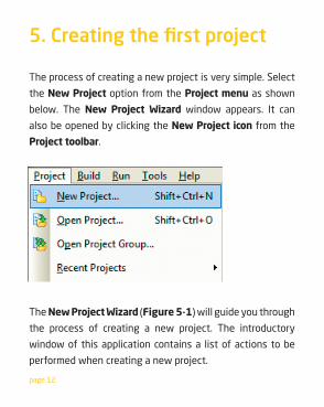
The process of creating a new project is very simple. Select
the New Project option from the Project menu as shown
below. The New Project Wizard window appears. It can
also be opened by clicking the New Project icon from the
Project toolbar.
The New Project Wizard (Figure 5-1) will guide you through
the process of creating a new project. The introductory
window of this application contains a list of actions to be
performed when creating a new project.
5. Creating the first project
page 13
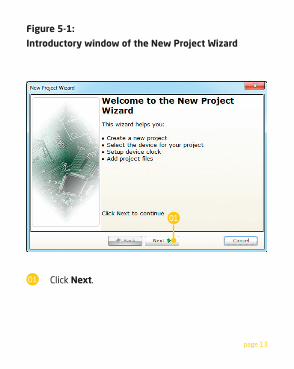
Click Next.
Figure 5-1:
Introductory window of the New Project Wizard
01
01
page 14
Step 1 - Project Settings
First thing we have to do is to specify the general
project information. This is done by selecting the target
microcontroller, its operating clock frequency, and of course
– naming our project. This is an important step, because
the compiler will adjust the internal settings based on this
information.Defaultconfiguration isalreadysuggestedto
us at the begining. We will not change the microcontroller,
and we will leave the default FT900 as the choice for this
project.
page 15
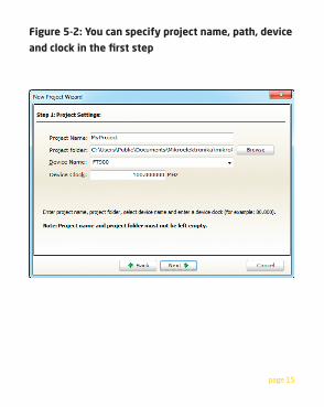
Figure 5-2: You can specify project name, path, device
and clock in the first step
page 16
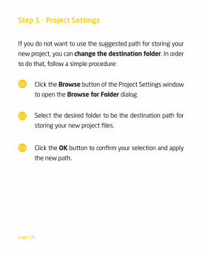
If you do not want to use the suggested path for storing your
new project, you can change the destination folder. In order
to do that, follow a simple procedure:
Step 1 - Project Settings
Click the Browse button of the Project Settings window
to open the Browse for Folder dialog.
Select the desired folder to be the destination path for
storingyournewprojectfiles.
Click the OKbuttontoconfirmyourselectionandapply
the new path.
01
02
03
page 17
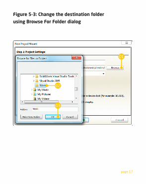
Figure 5-3: Change the destination folder
using Browse For Folder dialog
01
02
03
page 18
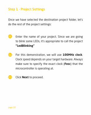
Once we have selected the destination project folder, let’s
do the rest of the project settings:
Step 1 - Project Settings
Enter the name of your project. Since we are going
to blink some LEDs, it’s appropriate to call the project
“LedBlinking”
For this demonstration, we will use 100MHz clock.
Clock speed depends on your target hardware. Always
make sure to specify the exact clock (Fosc) that the
microcontroller is operating at.
Click Next to proceed.
01
02
03
page 19
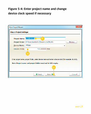
Figure 5-4: Enter project name and change
device clock speed if necessary
03
01
02
page 20
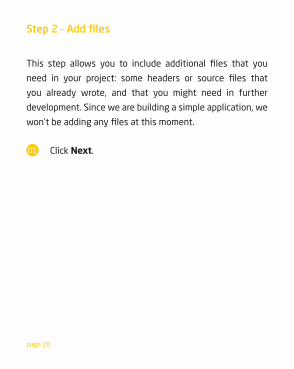
Click Next.
This step allows you to include additional files that you
need in your project: some headers or source files that
you already wrote, and that you might need in further
development. Since we are building a simple application, we
won’tbeaddinganyfilesatthismoment.
Step 2 - Add files
01
page 21
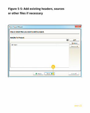
Figure 5-5: Add existing headers, sources
or other files if necessary
01
page 22
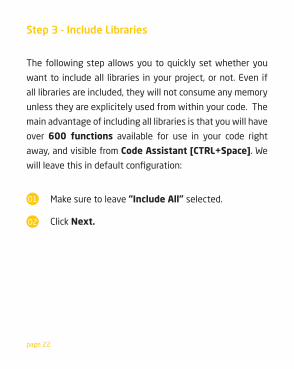
The following step allows you to quickly set whether you
want to include all libraries in your project, or not. Even if
all libraries are included, they will not consume any memory
unless they are explicitely used from within your code. The
main advantage of including all libraries is that you will have
over 600 functions available for use in your code right
away, and visible from Code Assistant [CTRL+Space]. We
willleavethisindefaultconfiguration:
Step 3 - Include Libraries
Make sure to leave “Include All” selected.
Click Next.
01
02
page 23
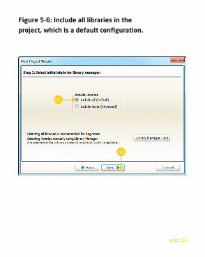
Figure 5-6: Include all libraries in the
project, which is a default configuration.
02
01
page 24
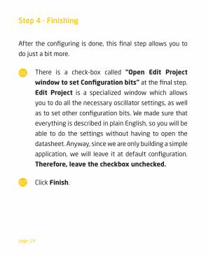
Aftertheconfiguringisdone,thisfinalstepallowsyouto
do just a bit more.
Step 4 - Finishing
There is a check-box called “Open Edit Project
window to set Configuration bits”atthefinalstep.
Edit Project is a specialized window which allows
you to do all the necessary oscillator settings, as well
astosetotherconfigurationbits.Wemadesurethat
everything is described in plain English, so you will be
able to do the settings without having to open the
datasheet. Anyway, since we are only building a simple
application,wewill leave itatdefault configuration.
Therefore, leave the checkbox unchecked.
01
02 Click Finish.
page 25
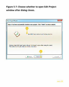
Figure 5-7: Choose whether to open Edit Project
window after dialog closes.
02
01
page 26
New project is finally created. A new source file called
“LedBlinking.c” is created and it contains the void main()
function, which will hold the program. You may notice that
theprojectisconfiguredaccordingtothesettingsdoneinthe
New Project Wizard.
Blank new project created
page 27
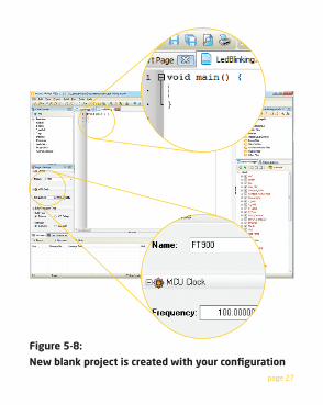
Figure 5-8:
New blank project is created with your configuration
page 28
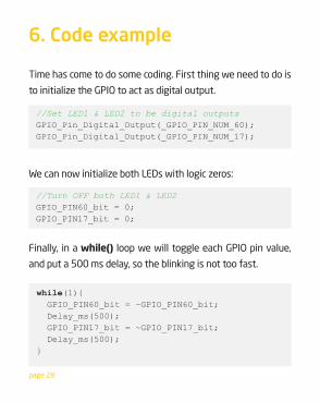
Finally, in a while() loop we will toggle each GPIO pin value,
and put a 500 ms delay, so the blinking is not too fast.
while(1){ GPIO_PIN60_bit = ~GPIO_PIN60_bit; Delay_ms(500); GPIO_PIN17_bit = ~GPIO_PIN17_bit; Delay_ms(500);}
6. Code example
Time has come to do some coding. First thing we need to do is
to initialize the GPIO to act as digital output.
We can now initialize both LEDs with logic zeros:
//Set LED1 & LED2 to be digital outputsGPIO_Pin_Digital_Output(_GPIO_PIN_NUM_60);GPIO_Pin_Digital_Output(_GPIO_PIN_NUM_17);
//Turn OFF both LED1 & LED2GPIO_PIN60_bit = 0;GPIO_PIN17_bit = 0;
page 29
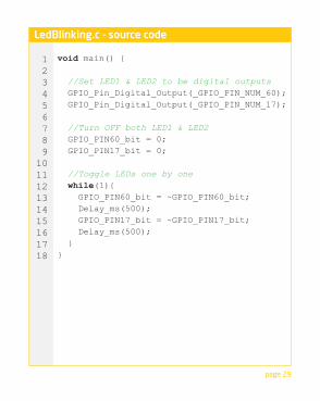
void main() {
//Set LED1 & LED2 to be digital outputs GPIO_Pin_Digital_Output(_GPIO_PIN_NUM_60); GPIO_Pin_Digital_Output(_GPIO_PIN_NUM_17);
//Turn OFF both LED1 & LED2 GPIO_PIN60_bit = 0; GPIO_PIN17_bit = 0;
//Toggle LEDs one by one while(1){ GPIO_PIN60_bit = ~GPIO_PIN60_bit; Delay_ms(500); GPIO_PIN17_bit = ~GPIO_PIN17_bit; Delay_ms(500); }}
123456789
101112131415161718
LedBlinking.c - source code
page 30
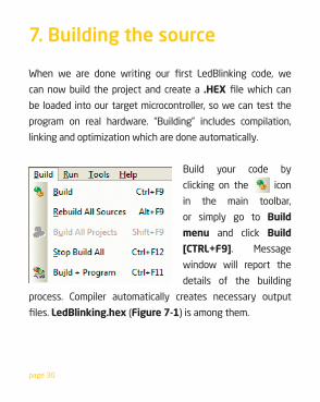
When we are done writing our first LedBlinking code, we
can now build the project and create a .HEX filewhichcan
be loaded into our target microcontroller, so we can test the
program on real hardware. “Building” includes compilation,
linking and optimization which are done automatically.
Build your code by
clicking on the icon
in the main toolbar,
or simply go to Build
menu and click Build
[CTRL+F9]. Message
window will report the
details of the building
process. Compiler automatically creates necessary output
files.LedBlinking.hex (Figure 7-1) is among them.
7. Building the source
page 31
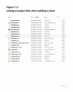
Figure 7-1:
Listing of project files after building is done
page 32
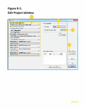
If you need to change the target microcontroller or
clock speed, you don’t have to go through the new
project wizard all over again. This can be done quickly
in the Edit Project window. You can open it using
Project->Edit Project [CTRL+SHIFT+E] menu option.
8. Changing project settings
To change your MCU, just select the desired
microcontroller from the dropdown list.
To change your settings enter the oscillator value and
adjust configuration register bits using drop-down
boxes.
Several most commonly used settings can be loaded
using the provided oscillator “schemes”. Load the desired
scheme by clicking the Load Scheme button.
01
02
03
page 33
Figure 8-1:
Edit Project Window
01
03
02
02
page 34
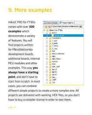
9. More examples
mikroC PRO for FT90x
comes with over 300
examples which
demonstrate a variety
of features. You will
findprojectswritten
for MikroElektronika
development boards,
additional boards, internal
MCU modules and other
examples. This way you
always have a starting
point, and don’t have to
start from scratch. In most
cases, you can combine
differentsimpleprojectstocreateamorecomplexone.All
projectsaredeliveredwithworking.HEXfiles,soyoudon’t
have to buy a compiler license in order to test them.
page 35
DISCLAIMER
All the products owned by MikroElektronika are protected by copyright law and international copyright treaty.
Therefore, this manual is to be treated as any other copyright material. No part of this manual, including
product and software described herein, may be reproduced, stored in a retrieval system, translated or
transmitted in any form or by any means, without the prior written permission of MikroElektronika. The
manualPDFeditioncanbeprintedforprivateorlocaluse,butnotfordistribution.Anymodificationofthis
manual is prohibited.
MikroElektronika provides this manual ‘as is’ without warranty of any kind, either expressed or implied,
including,butnotlimitedto,theimpliedwarrantiesorconditionsofmerchantabilityorfitnessforaparticular
purpose.
MikroElektronika shall assume no responsibility or liability for any errors, omissions and inaccuracies that may
appearinthismanual.InnoeventshallMikroElektronika,itsdirectors,officers,employeesordistributorsbe
liableforanyindirect,specific,incidentalorconsequentialdamages(includingdamagesforlossofbusiness
profitsandbusinessinformation,businessinterruptionoranyotherpecuniaryloss)arisingoutoftheuse
of this manual or product, even if MikroElektronika has been advised of the possibility of such damages.
MikroElektronika reserves the right to change information contained in this manual at any time without prior
notice, if necessary.
TRADEMARKSThe MikroElektronika name and logo, the MikroElektronika logo, mikroC™, mikroBasic™, mikroPascal™,
mikroProg™, EasyFT90x™ v7, mikromedia, clicker 2™, mikroBUS™, click™ boards are trademarks of
MikroElektronika. All other trademarks mentioned herein are property of their respective companies.
All other product and corporate names appearing in this manual may or may not be registered trademarks
orcopyrightsoftheirrespectivecompanies,andareonlyusedforidentificationorexplanationandtothe
owners’benefit,withnointenttoinfringe.
Copyright © MikroElektronika, 2015, All Rights Reserved.
HIGH RISK ACTIVITIESThe products of MikroElektronika are not fault – tolerant nor designed, manufactured or intended for
use or resale as on – line control equipment in hazardous environments requiring fail – safe performance,
suchasintheoperationofnuclearfacilities,aircraftnavigationorcommunicationsystems,airtraffic
control, direct life support machines or weapons systems in which the failure of Software could lead
directly to death, personal injury or severe physical or environmental damage (‘High Risk Activities’).
MikroElektronikaanditssuppliersspecificallydisclaimanyexpressedorimpliedwarrantyoffitness
for High Risk Activities.

mikroCPRO for FT90x
If you want to learn more about our products, please visit our web site at www.mikroe.com. If you are experiencing some problems with any of our products or just need additional information, please place your ticket at www.mikroe.com/support. If you have any questions, comments or business proposals, do not hesitate to contact us at [email protected]
Designed byMikroElektronika Ltd
2015.
CTFP in mikroC PROfor FT90x bundle manual
ver 1.01
0100000071571
CTFP in mikroC PROfor FT90x bundle manual
ver 1.01
0100000071571


