Modified July 2008 IMPORTANT: Become familiar with the contents of this manual and the Dingo Operation and Maintenance manual before operating the Trencher attachment. Information about the Dingo is contained in the Dingo Operation and Maintenance Manual. OPERATION & MAINTENANCE MANUAL DINGO™ PRO SERIES TRENCHER WHEEL MOTOR TRENCHER
Transcript
Modified July 2008
IMPORTANT: Become familiar with the contents of this manual and the Dingo Operation and Maintenance manual before operating the Trencher attachment. Information about the Dingo is contained in the Dingo Operation and Maintenance Manual.
IntroductionThis trencher has been carefully designed and manufactured to give you years of reliable service. Please read this operation and safety manual to keep your trencher running efficiently.
The information in this manual is current as at December 2007. In the effort to continually improve our products, Dingo reserves the right to change specifications without notice. Please, for critical information, contact you nearest Dingo branch.
We want you to be completely satisfied with your new product, so feel free to contact your local Dingo branch for help with service, replacement parts and any other information about the Dingo and its attachments.
DISCLAIMER:Specifications, design & service procedures are subject to change without notice.Specifications may vary & may be approximate.
Whenever you contact your local Dingo branch always know the model and serial numbers of your product. These numbers will help us to provide exact information about your specific product. You will find the model and serial number on a plate located on the product.
For your convenience, write the product model and serial numbers in the space below.
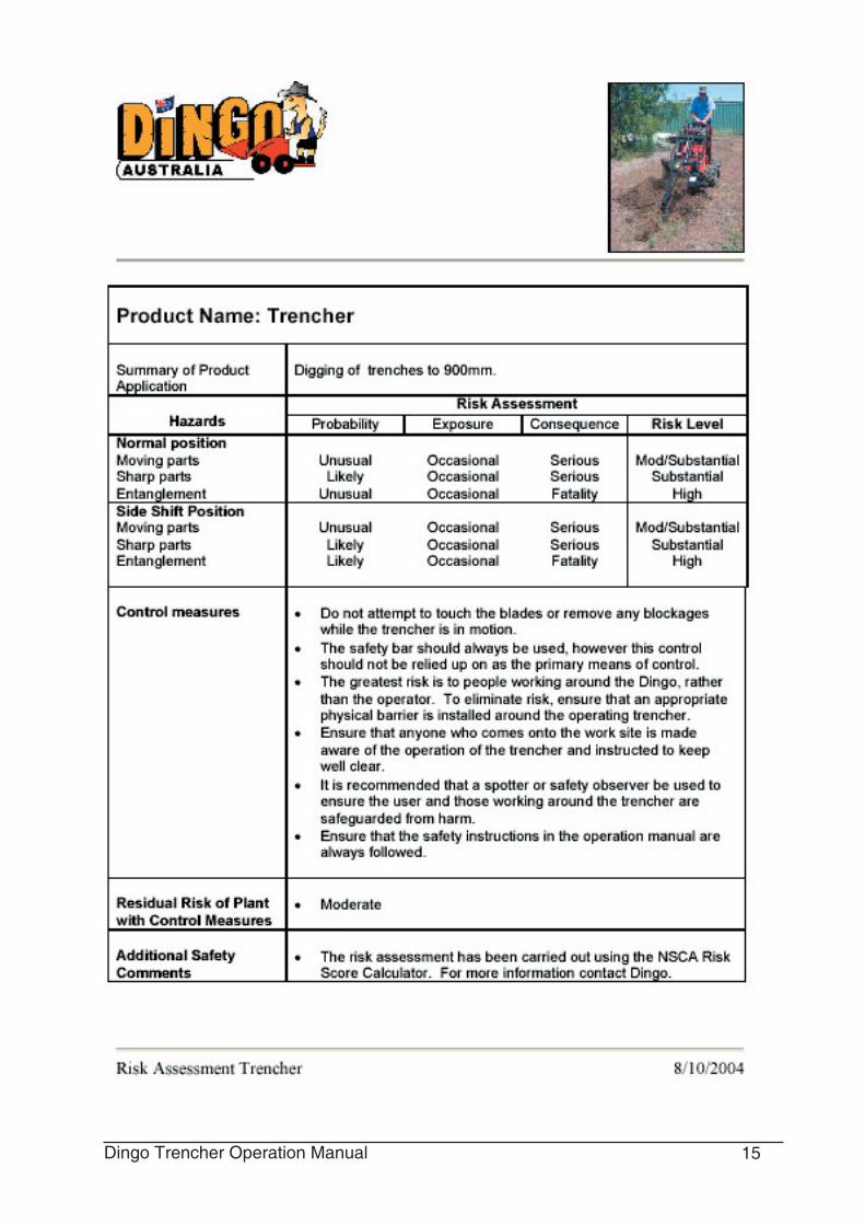
Safetyn Keep away from the moving teeth and auger while operating the trencher. n Keep your hands, feet, and any other part of your body or clothing away from movng parts.
n Before adjusting, cleaning, repairing and inspecting the trencher, shut off the engine and wait for all moving parts to stop. Lower the trencher and Dingo arms to the ground and rotate the ignition key to “OFF.”
Operation1. Ensure Auxiliary hydraulics lever is in neutral position before connecting Trencher.
2. Disconnect Bucket or other attachment and connect Trencher as per instructions in the Dingo Operation and Maintenance Manual. Follow all steps for connecting an attachment that requires auxiliary hydraulics. The Dingo Operation and Maintenance Manual explains the use of the auxiliary hydraulics lever.
3. After the trencher has been mounted and hooked up hydraulically, inspect thoroughly to be certain it is in good working order before use. The following check list is a reminder of points inspect.
• Mount trencher to Dingo and check all latching.points for correct fit.
• Check hose routing at pivot points to be sure proper clearance or slack is available during all operations.
• Check digging chain adjustment. If in doubt, err .on the side of too loose. It is better to be too loose than too tight.
• Check all hose connections for leaks.
4. Manoeuvre machine so that the end of the
trencher is positioned at the start of the desired trench with rear of machine facing the direction of the trench. Trenching will be done whilst pulling back and operating in a reverse direction.
5. Move the pump selector to the turtle position. In this position the big pump is powering the trencher and the small pump is powering the wheels and arms.
6. With the trencher a little off the ground and parallel to the ground start trencher teeth moving by using auxiliary lever. Trencher teeth on top side of trencher should be moving away from the ma-chine.
7. Tilt the trencher down into the ground using the crowd lever. As the trencher enters the ground it will be necessary to lift the rear of the trencher using the lift lever. This will ensure the rear of the trencher and the auger flight remain just above the ground.
8. Once the correct depth is achieved move the flow divider lever to the 9 o’clock position or to the indicated trenching range on the K94 flow divider. Pull both drive levers fully back. Then gradually move the flow divider lever towards the 10 o’clock position until a satisfactory ground speed is achieved for the trenching conditions. This may have to be varied from time to time. If the wheels are starting to spin you are trying to travel too fast.
9. When finished digging, tilt the trencher out of the trench and back away from the trench before driving away. Be careful not to drive near the trench or any other obstacle. Remove the trencher as per instructions in the Dingo Operation and Maintenance Manual.
10. It is best to trench with the angle of the trencher determining the depth of the trench. I.E. Keep the back of the trencher and the side auger just clearing the original ground surface.
MaintenanceThe Dingo trencher has no real service schedule that need to be adhered to but has several wear parts that you should keep an eye on.
Teeth
Sharp teeth are important to good performance. When teeth wear out, Production will drop sharply, increas-ing wear and tear on other components.
Cup teeth wear on the tip and side bulge in varying amounts. Wear patterns change with different dig-ging conditions. Rocks will take the points off faster than sides. Sandstone or highly abrasive material will wear out the side bulges faster. Rock will be the most severe type of digging conditions.
The following patterns and captions are approximate and should be used as a guide to help you determine your own best cost/benefit tooth replacement time.
In soft soil, tooth wear does not reduce performance as rapidly as hard soils.
Normal replacement should be made between 30% and 60% reduction in performance.
Rock teeth and chains (Diggatac) will greatly improve cost/benefits in severe materials.
Rock chains do not work well in dirt, as they do not have good soil removal capabilities.
New 20% Reduction 50% Reduction 70% Reduction Beyond In In In Usefulness
Chain
The chain is also a wear part. Throughout the chains life you will notice the bottoms of each link and the rollers within each link will start to wear.
Chain Front Rear Link Roller RollerAs a result of the digging action the rear roller in each link will wear faster than the front roller. To prolong the life of your chain it is a good idea to remove the teeth and replace them in the reverse direction. This can be done at the midpoint of the chain’s life and when replacing a worn set of teeth. By doing this the rear roller becomes the front roller and the chain has a chance of wearing evenly.
Chain Adjustment
To check the chain tension on the trencher, leave it attached to the Dingo and raise it in the air parallel to the ground.
There should be 50-100mm of slack in the chain, measured between the chain and the bottom of the boom (usually about 3 fingers distance)
IMPORTANT: Do not over tighten the chain. Excess chain tension may damage drive components and increase the chances of the chain stalling in loose material.
Should the chain need adjustment, use the following four steps.1 Lower the trencher and stop the engine.2 Remove the spanner from the side of the trencher. Note: The butt of the spanner locks the adjustment nut.3 Using the spanner, rotate the adjustment nut counterclockwise to extend the trencher boom to tighten the chain.4 Replace the spanner in the storage position to .......lock the adjustment nut in place.
Teeth are left or right hand as viewed from standing position on machine.
Generally teeth are marked as follows:-
Nose Roller AssemblyThe nose roller assembly (item 14, page 11) is also a wear part. A worn nose roller assembly will increase chain wear. Do not lubricate the bearing in the as-sembly as this will attract dirt to the bearing and reduce its life-span. It is a sealed bearing.
Drive SprocketThe drive sprocket (item 7, page 11) is a wear part. A worn sprocket will reduce the life of your chain. It is recommended to replace the sprocket and chain at the same time.
BoomThe boom (item 10, page 11) is a wear part. By the time the skid plate on the underside is worn out, so is the adjuster thread and the area where the boom enters its socket. Replacement of the complete boom is recommended.
Off-setting the TrencherThe Dingo trencher has the ability to be off-set so that it is possible to trench up against wall, fences etc.
1 Undo the 6 bolts holding the planetary drive mount ...to the mount assembly.2 Replace the planetary mount on the right hand side ...of the mount assembly in the six holes provided.3 Remove the auger flight.4 Remove the safey rail assembly.
In the off-set position the trencher chain is now in line with the outside of the wheels.
Abbreviations used:L = Left Hand ToothR = Right hand toothCL = Centre LeftCR = Centre Right6L = tooth spaced 6” to the left6R = Tooth spaced 6” to the right8” = teeth on both sides of 8” spacer10” = Teeth on both sides of 10” spacer12” = Teeth on both sides of 12” spacerSP = space or blank
PositionCut Width
4” 6” 8” 10” 12”1 CR CR CR CR CR2 L L L L L3 R R R R R4 SP 6L 6L 6L 6L5 CR 6R 6R 6R 6R6 L L 8” 8” 8”7 R R R SP SP8 SP SP SP 10” 12”9 CL CL CL CL CL
10 L L L L L11 R R R R R12 SP 6L 6L 6L 6L13 CL 6R 6R 6R 6R14 L L 8” 8” 10”15 R R L SP SP16 SP SP SP 10” 12”17 CR CR CR CR CR18 L L L L L19 R R R R R20 SP 6L 6L 6L 6L21 CR 6R 6R 6R 6R22 L L 8” 8” 8”23 R R R SP SP24 SP SP SP 10” 12”25 CL CL CL CL CL26 L L L L L27 R R R R R28 SP 6L 6L 6L 6L29 CL 6R 6R 6R 6R30 L L 8” 8” 10”31 R R L SP SP32 SP SP SP 10” 12”
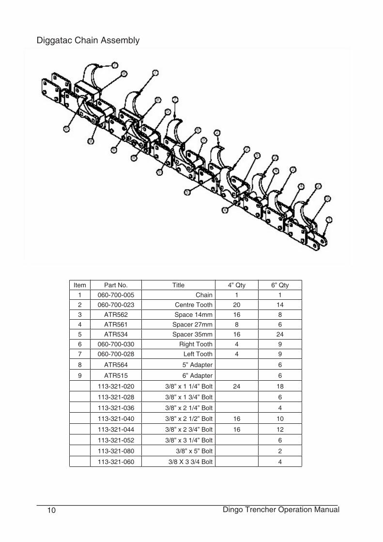
Diggatac ChainDiggatac is a unique bolt on hard digging and rock tooth that gives incredible tooth life and high perfor-mance in those difficult trenching conditions. Mining grade tungsten carbide tools are used to provide longer life.
Rear View
Side View
Left Centre Right (Straight)
Diggatac Chain Tooth Configuration
Abbreviations:C Centre - straight toothSP SpaceILS Inside left - straight toothIRS Inside right - straight toothOLS Outside left - straight toothORS Outside right - straight toothL4” Left toothR4” Right toothL5” Left tooth with 5”spacerR5” Right tooth with 5” spacerL6” Left tooth with 6” spacerR6” Right Tooth with 6” spacer
Diggatac Tooth Identification
Position 4” Cut 6” Cut1 C C2 ILS ILS3 IRS IRS4 OLS OLS5 ORS ORS6 L4” L4”7 R4” R4”8 SP L5”9 C R5”
10 ILS L6”11 IRS R6”12 OLS C13 ORS ILS14 L4” IRS15 R4” OLS16 SP ORS17 C L4”18 ILS R4”19 IRS L5”20 OLS R5”21 ORS L6”22 L4” R6”23 R4” ILS24 SP IRS25 C OLS26 ILS ORS27 IRS L4”28 OLS R4”29 ORS L5”30 L4” R5”31 R4” L + R 6”32 SP SP
The Wheel Motor Trencher is to be used with 4" & 6" wide chains fitted with cup teeth only.No Diggatac teeth are to be fittedFailure to comply with any of these requirements will void your warranty.The depth of cut for this type of Trencher is limited to 600mm.The Wheel Motor Trencher has a fixed position boom that cannot be offset.A Crumber Bar can not be fitted .The same maintenance & safety procedures/precautions as the Pro Series Trencher apply to the Wheel Motor Trencher.
PROBLEM POSSIBLE CAUSE AND REMEDY Chain does not turn 1. Sand build up or other obstruction in tooth root of sprocket A. Raise out of ditch, reverse chain & run to clear build up. B. Loosen chain tension. 2. Quick coupler not completely engaged - Check and complete engagement 3. Quick coupler failure - Replace faulty coupler 4. An obstruction in one of the hoses - Remove obstruction 5. Auxiliary valve on Dingo not properly open- ing - Check and repair 6. Hydraulic motor failure - Repair or replace. Contact dealer. 7. Chain drive failure - Check and repair. Contact dealer 8. Boom end bearing failed - Replace bearing 9. Digging chain to tight - Loosen chain tension. 10. Gear train failure - Check and repair. Contact dealer. 11. Drive shaft bearing - Check and repair. Contact dealer. Does not dig fast enough 1. Worn teeth - See section of this manual on tooth wear & replace if necessary. 2. Relief valve set below specifications - Test and reset if necessary 3. Quick coupler or hose restriction - Inspect and repair if necessary. 4. Hydraulic system too hot - Shut down and cool & refer to below 5. Cutting a trench size beyond the machine capabilities
Hydraulic oil overheating 1. Relief valve set too low on Dingo. - Test and set as needed 2. Restriction in Quick coupler or hose - Inspect and repair as needed - Stop and allow to cool naturally when it gets hot. 3. Hydraulic oil damaged or incorrect type - Replace Dingo oil with recommended oil 4. Pumps on Dingo worn or damaged - Replace pumps. Trenching boom or crumber bent 1. Abuse - Replace
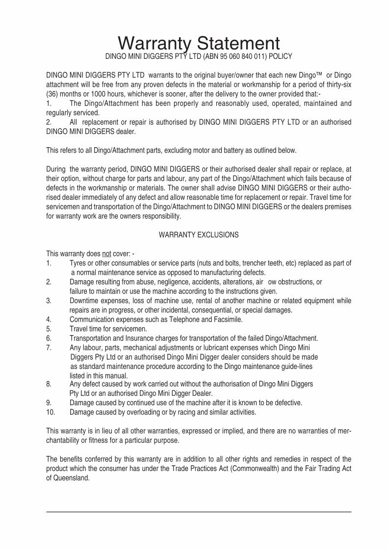
8. Any defect caused by work carried out without the authorisation of Dingo Mini Diggers Pty Ltd or an authorised Dingo Mini Digger Dealer. 9. Damage caused by continued use of the machine after it is known to be defective.10. Damage caused by overloading or by racing and similar activities.
This warranty is in lieu of all other warranties, expressed or implied, and there are no warranties of mer-chantability or fitness for a particular purpose.
The benefits conferred by this warranty are in addition to all other rights and remedies in respect of the product which the consumer has under the Trade Practices Act (Commonwealth) and the Fair Trading Act of Queensland.
DINGO MINI DIGGERS PTY LTD warrants to the original buyer/owner that each new Dingo™ or Dingo attachment will be free from any proven defects in the material or workmanship for a period of thirty-six (36) months or 1000 hours, whichever is sooner, after the delivery to the owner provided that:-1. The Dingo/Attachment has been properly and reasonably used, operated, maintained and regularly.serviced.2. All replacement or repair is authorised by DINGO MINI DIGGERS PTY LTD or an authorised DINGO MINI DIGGERS dealer.
This refers to all Dingo/Attachment parts, excluding motor and battery as outlined below.
During the warranty period, DINGO MINI DIGGERS or their authorised dealer shall repair or replace, at their option, without charge for parts and labour, any part of the Dingo/Attachment which fails because of defects in the workmanship or materials. The owner shall advise DINGO MINI DIGGERS or their autho-rised dealer immediately of any defect and allow reasonable time for replacement or repair. Travel time for servicemen and transportation of the Dingo/Attachment to DINGO MINI DIGGERS or the dealers premises for warranty work are the owners responsibility.
WARRANTY EXCLUSIONS
This warranty does not cover: -1. Tyres or other consumables or service parts (nuts and bolts, trencher teeth, etc) replaced as part of ..............a normal maintenance service as opposed to manufacturing defects.2. Damage resulting from abuse, negligence, accidents, alterations, air flow obstructions, or failure to maintain or use the machine according to the instructions given.3. Downtime expenses, loss of machine use, rental of another machine or related equipment while .............repairs are in progress, or other incidental, consequential, or special damages.4. Communication expenses such as Telephone and Facsimile.5. Travel time for servicemen.6. Transportation and Insurance charges for transportation of the failed Dingo/Attachment.7. Any labour, parts, mechanical adjustments or lubricant expenses which Dingo Mini Diggers Pty Ltd or an authorised Dingo Mini Digger dealer considers should be made as standard maintenance procedure according to the Dingo maintenance guide-lines listed in this manual.
Machines of this type can be dangerous if used carelessly or improperly. The manufacturer, distributor or selling agent does not accept responsibility for accident either to the operator, to the owner or to any person directly or indirectly or to property if such an accident is caused by circumstances arising otherwise than by the negligence or default of Dingo Mini Diggers Pty Ltd.
PARTS INSTALLED DURING MACHINE WARRANTY
Components installed during a machines warranty period shall have warranty coverage for the duration of the machine warranty period or ninety (90) days, which ever is greater, provided the warranty installation is performed by Dingo Mini Diggers Pty Ltd or an authorised Dingo Mini Digger dealer.
N.B. Dingo Mini Diggers Pty Ltd reserve the right to change at any time the Dingo Mini Digger product speci-fications, configurations, and company policies, this is due to our constant commitment to make the best product for the job.