120
Product Manual 26246 (Revision U, 5/2017) Original Instructions ProAct™ ISC Integrated Speed Control Actuator Models I through IV Installation and Operation Manual

Product Manual 26246 (Revision U, 5/2017)
Original Instructions
ProAct™ ISC Integrated Speed Control
Actuator Models I through IV
Installation and Operation Manual

General Precautions
Read this entire manual and all other publications pertaining to the work to be performed before installing, operating, or servicing this equipment.
Practice all plant and safety instructions and precautions.
Failure to follow instructions can cause personal injury and/or property damage.
Revisions
This publication may have been revised or updated since this copy was produced.
To verify that you have the latest revision, check manual 26455, Customer Publication Cross Reference and Revision Status & Distribution Restrictions, on the publications page of the Woodward website:
www.woodward.com/publications The latest version of most publications is available on the publications page. If your publication is not there, please contact your customer service representative to get the latest copy.
Proper Use
Any unauthorized modifications to or use of this equipment outside its specified mechanical, electrical, or other operating limits may cause personal injury and/or property damage, including damage to the equipment. Any such unauthorized modifications: (i) constitute "misuse" and/or "negligence" within the meaning of the product warranty thereby excluding warranty coverage for any resulting damage, and (ii) invalidate product certifications or listings.
Translated Publications
If the cover of this publication states "Translation of the Original Instructions" please note:
The original source of this publication may have been updated since this
translation was made. Be sure to check manual 26455, Customer Publication Cross Reference and Revision Status & Distribution Restrictions, to verify whether this translation is up to date. Out-of-date translations are marked with . Always compare with the original for technical specifications and for proper and safe installation and operation procedures.
Revisions—Changes in this publication since the last revision are indicated by a black line
alongside the text. Woodward reserves the right to update any portion of this publication at any time. Information provided by Woodward is believed to be correct and reliable. However, no responsibility is assumed by Woodward unless otherwise expressly undertaken.
Manual 26246 Copyright © Woodward 2003—2017
All Rights Reserved

Manual 26246 ProAct ISC
Woodward i
Contents
WARNINGS AND NOTICES .......................................................................... IV
ELECTROSTATIC DISCHARGE AWARENESS ................................................. V
REGULATORY COMPLIANCE ...................................................................... VI
CHAPTER 1. GENERAL INFORMATION .......................................................... 1 Purpose and Scope ................................................................................................ 1 Intended Applications ............................................................................................. 1 Introduction ............................................................................................................. 1 Basic Control Options ............................................................................................. 2 Service Tool Software ............................................................................................ 2 References ............................................................................................................. 2
CHAPTER 2. INSTALLATION ........................................................................ 7 Introduction ............................................................................................................. 7 Unpacking and Handling ........................................................................................ 7 Mounting Location .................................................................................................. 8 Electrical Connections .......................................................................................... 11
CHAPTER 3. DESCRIPTION OF OPERATION ................................................ 20 General ................................................................................................................. 20 System Operation ................................................................................................. 21 Controller Features Description ............................................................................ 21 Actuator Function ................................................................................................. 21 Speed Control Functions ...................................................................................... 22 Speed Control Dynamics ...................................................................................... 27 Start Fuel Limiting ................................................................................................. 29 Runtime Fuel Limiting ........................................................................................... 30 Analog Output ....................................................................................................... 32 Discrete Output ..................................................................................................... 33 Temperature Sensing ........................................................................................... 33 Current Limiting based on Temperature ............................................................... 33 ProAct ISC Alarms and Shutdowns ...................................................................... 34
CHAPTER 4. SERVICE TOOL ..................................................................... 37 Description ............................................................................................................ 37 Getting Started ..................................................................................................... 38 Monitoring the Driver ............................................................................................ 39
CHAPTER 5. CONFIGURATION ................................................................... 46 Introduction ........................................................................................................... 46 Overview ............................................................................................................... 46 Configuration Parameters..................................................................................... 47
CHAPTER 6. SETUP, CALIBRATION, AND TUNING ....................................... 71 Introduction ........................................................................................................... 71 Control Setup ........................................................................................................ 71 Position Calibration and Verification ..................................................................... 72 Tuning the Speed Control Dynamics .................................................................... 75
CHAPTER 7. SOFTWARE UPGRADE PROCEDURE ....................................... 78 Introduction ........................................................................................................... 78 Install Watch Window Professional ...................................................................... 78 Install ProAct ISC Service Tool ............................................................................ 78

ProAct ISC Manual 26246
ii Woodward
Contents
CHAPTER 8. CAN DETAILS ...................................................................... 79 Overview ...............................................................................................................79 CAN Bit Timing .....................................................................................................79 Source Address/Harness Code Strategy .............................................................79 Configuration Strategy ..........................................................................................79 CAN Messages .....................................................................................................79 Diagnostics from ProAct ISC ................................................................................81 Diagnostics/Events ...............................................................................................82 Event Codes .........................................................................................................83 Transmission Rate ................................................................................................83 Arbitration .............................................................................................................84
CHAPTER 9. TROUBLESHOOTING .............................................................. 85 Introduction ...........................................................................................................85 Troubleshooting the ProAct ISC ...........................................................................85 Troubleshooting Diagnostic Flags ........................................................................87
CHAPTER 10. PRODUCT SUPPORT AND SERVICE OPTIONS ......................... 92 Product Support Options ......................................................................................92 Product Service Options .......................................................................................92 Returning Equipment for Repair ...........................................................................93 Replacement Parts ...............................................................................................93 Engineering Services ............................................................................................94 Contacting Woodward’s Support Organization ....................................................94 Technical Assistance ............................................................................................95
APPENDIX A. PROACT ISC CONTROL MODES ........................................... 96 Introduction ...........................................................................................................96 State Descriptions.................................................................................................96 State Transitions ...................................................................................................97
APPENDIX B. PROACT GENERAL SPECIFICATIONS .................................. 105
REVISION HISTORY ................................................................................ 107
DECLARATIONS ..................................................................................... 108

Manual 26246 ProAct ISC
Woodward iii
Illustrations and Tables Figure 1-1. Outline Drawing, Models I and II .......................................................... 3 Figure 1-2. Outline Drawing, Model III .................................................................... 4 Figure 1-3. Outline Drawing, Model IV ................................................................... 5 Figure 1-4. Control Wiring Diagram ........................................................................ 6 Figure 2-1. Fuel Stops .......................................................................................... 10 Figure 2-2. Correct and Incorrect Wiring to Power Supply ................................... 13 Figure 3-1. Remote Speed Setpoint Operation .................................................... 25 Figure 3-2. Speed Droop ...................................................................................... 27 Figure 3-3. Control Gain as a Function of Speed Error ........................................ 28 Figure 3-4. Start Fuel Limit ................................................................................... 29 Figure 3-5. Dual Start Fuel Limit with Ramp ........................................................ 30 Figure 3-6. Runtime Fuel Limiting Curve .............................................................. 31 Figure 3-7. Boost (External) Fuel Limit ................................................................. 32 Figure 3-8. Temperature vs. Current Limit ........................................................... 33 Figure 4-1. Communication Harness Connections .............................................. 37 Figure 4-2. Service Tool Screen Example ............................................................ 38 Figure 4-3a. Service Tool—Overview Tab (Speed Control) ................................. 41 Figure 4-3b. Service Tool—Overview Tab (Position Control) .............................. 41 Figure 4-4. Service Tool—Alarms Tab ................................................................. 43 Figure 4-5. Service Tool—Shutdowns Tab .......................................................... 44 Figure 4-6. Service Tool—Internal Shutdowns Tab ............................................. 44 Figure 4-7. Service Tool—Identification Tab ........................................................ 45 Figure 8-1. Typical Arbitration Field Example ...................................................... 84 Figure A-1. Start Fuel State When Two Start Fuels are Configured .................... 98 Figure A-2. Running State When Configured for Rated Speed Setpoint ............. 99 Figure A-3. Running State When Configured for Idle / Rated Speed Setpoint .... 99 Figure A-4. Running State When Configured for Runtime Select Rated 1 / 2
Speed Setpoint .............................................................................. 100 Figure A-5. Running State When Configured for Start-up Select Rated 1 / 2
Speed Setpoint .............................................................................. 100 Figure A-6. Start Fuel Diagram .......................................................................... 103 Figure A-7. Speed Setpoint Diagram ................................................................. 104 Figure B-1. Transfer Function ............................................................................ 105

ProAct ISC Manual 26246
iv Woodward
Warnings and Notices
Important Definitions This is the safety alert symbol. It is used to alert you to potential personal injury hazards. Obey all safety messages that follow this symbol to avoid possible injury or death.
DANGER—Indicates a hazardous situation which, if not avoided, will result in death or serious injury.
WARNING—Indicates a hazardous situation which, if not avoided, could result in death or serious injury.
CAUTION—Indicates a hazardous situation which, if not avoided, could result in minor or moderate injury.
NOTICE—Indicates a hazard that could result in property damage only (including damage to the control).
IMPORTANT—Designates an operating tip or maintenance suggestion.
Overspeed / Overtemperature /
Overpressure
The engine, turbine, or other type of prime mover should be equipped with an overspeed shutdown device to protect against runaway or damage to the prime mover with possible personal injury, loss of life, or property damage.
The overspeed shutdown device must be totally independent of the prime mover control system. An overtemperature or overpressure shutdown device may also be needed for safety, as appropriate.
Personal Protective Equipment
The products described in this publication may present risks that could lead to personal injury, loss of life, or property damage. Always wear the appropriate personal protective equipment (PPE) for the job at hand. Equipment that should be considered includes but is not limited to:
Eye Protection
Hearing Protection
Hard Hat
Gloves
Safety Boots
Respirator
Always read the proper Material Safety Data Sheet (MSDS) for any working fluid(s) and comply with recommended safety equipment.
Start-up
Be prepared to make an emergency shutdown when starting the engine, turbine, or other type of prime mover, to protect against runaway or overspeed with possible personal injury, loss of life, or property damage.
Automotive Applications
On- and off-highway Mobile Applications: Unless Woodward's control functions as the supervisory control, customer should install a system totally independent of the prime mover control system that monitors for supervisory control of engine (and takes appropriate action if supervisory control is lost) to protect against loss of engine control with possible personal injury, loss of life, or property damage.

Manual 26246 ProAct ISC
Woodward v
Battery Charging Device
To prevent damage to a control system that uses an alternator or battery-charging device, make sure the charging device is turned off before disconnecting the battery from the system.
Electrostatic Discharge Awareness Prior to making any connections to the product, personnel should ensure that they are free of electrostatic build-up in order to protect the integrity of the device’s circuitry. The simplest method for dissipating electrostatic build-up is to contact an adjacent, grounded metal object before contacting the product.
The product circuit boards should only be removed or repaired by authorized Woodward personnel. In the event this is required, authorized personnel must follow the ESD mitigation procedures described in Woodward manual 82715, Guide for Handling and Protection of Electronic Controls, Printed Circuit Boards, and Modules, to ensure circuit board integrity is maintained during repair or replacement.

ProAct ISC Manual 26246
vi Woodward
Regulatory Compliance European Compliance for CE Marking: These listings are limited only to those units bearing the CE Marking. EMC Directive: Declared to Directive 2014/30/EU of the
European Parliament and of the Council of 26 February 2014 on the harmonization of the laws of the Member States relating to electromagnetic compatibility (EMC)
Other European Compliance: Compliance with the following European Directives or standards does not qualify this product for application of the CE Marking. Machinery Directive: Compliant as partly completed machinery with
Directive 2006/42/EC of the European Parliament and the Council of 17 May 2006 on machinery.
North American Compliance: These listings are limited only to those units bearing the CSA agency identification. CSA: CSA Certified for Class I, Division 2, Groups A,
B, C & D, T3 at 85 °C Ambient for use in Canada and the United States.
Certificate 1167451 Type 3R Enclosure Rainproof This product is certified as a component for use
in other equipment. The final combination is subject to acceptance by CSA International (or UL) or local inspection.
The ProAct™ ISC is suitable for use in Class I, Division 2, Groups A, B, C, and D per CSA for Canada and US or non-hazardous locations only. The ProAct ISC wiring must be in accordance with North American Class I, Division 2 or Zone 2 wiring methods as applicable, and in accordance with the authority having jurisdiction. Field wiring must be suitable for at least 85 °C. Connect the ground terminal of the ProAct ISC to earth ground. I/O cabling for the ProAct ISC is limited to 30 m (100 ft) for surge compliance. Compliance with the Machinery Directive 2006/42/EC noise measurement and mitigation requirements is the responsibility of the manufacturer of the machinery into which this product is incorporated.

Manual 26246 ProAct ISC
Woodward vii
EXPLOSION HAZARD—Do not connect or disconnect while circuit is live unless area is known to be non-hazardous. Substitution of components may impair suitability for Class I, Division 2 or Zone 2 applications.
RISQUE D’EXPLOSION—Ne pas raccorder ni débrancher tant que l’installation est sous tension, sauf en cas l’ambiance est décidément non dangereuse. La substitution de composants peut rendre ce matériel inacceptable pour les emplacements de Classe I, applications Division 2 ou Zone 2.
Due to the hazardous location listings associated with this product, proper wire type and wiring practices are critical to operation.
Do not connect any cable grounds to “instrument ground”, “control ground”, or any non-earth ground system. Make all required electrical connections based on the wiring diagram (Figure 1-4).
If the electronics are removed or disconnected form the actuator, the calibration of the position has been lost. This calibration can only be done at Woodward production.

ProAct ISC Manual 26246
viii Woodward

Manual 26246 ProAct ISC
Woodward 1
Chapter 1. General Information
Purpose and Scope The purpose of this manual is to provide the necessary background information for applying the ProAct™ Integrated Speed Control (ISC) to diesel and gaseous-fueled reciprocating engines. Topics covered include mechanical installation, electrical wiring, software programming, and troubleshooting. This manual revision applies to all ProAct ISC versions with software 5418-2374, 5418-2755, 5418-2949, or 5418-3777. The software part number is provided on the Identification tab of the Service Tool. A configurable shutdown direction was added to the 5418-2755 version, a configurable CAN baud rate is provided in the 5418-2949 version, and support for Model 4 EHT versions was added in the 5418-3777 version.
Intended Applications The ProAct ISC control is designed for various industrial applications, including but not limited to generator sets, mechanical drives, pumps and compressors. The ProAct ISC is generally applicable to engines in the 300 kW to 1200 kW output range. The ProAct ISC is a suitable replacement for mechanical systems that need more flexibility in control strategy, such as dual dynamics, idle/rated dynamics, and gain curves. The ProAct ISC is CSA approved for Class I, Division 2, Groups A, B, C, and D hazardous locations and is designed for on-engine mounting. Full ProAct ISC specifications are listed near the end of this manual.
Introduction The Woodward ProAct Integrated Speed Control (ISC) combines the proven ProAct electric actuator with integrated speed control software to control the speed of diesel and gaseous fuel engines. The ProAct ISC is a microprocessor-based speed control incorporated into the actuator, creating a single integrated actuator/speed control. This eliminates the need for an additional driver box and speed control box. The ProAct ISC can also be configured as a position control only for basic actuator applications. The ProAct ISC position control accepts 4–20 mA, 0–5 V, ±3 V, or CAN position command signal. The ProAct ISC control uses state-of-the-art speed sensing and control algorithms. It also performs comprehensive diagnostics for easy troubleshooting. The ProAct ISC is configured and tuned using the ProAct ISC Service Tool. The modular bi-directional actuator design easily attaches to fuel pumps, fuel valves, or throttle bodies.

ProAct ISC Manual 26246
2 Woodward
Basic Control Options Position control with software support for:
CW / CCW (clockwise/counterclockwise) direction control
Field calibration options
Speed control with software selectable:
Speed setpoints
Dynamics
Fuel Limiting
Input/Output Definitions Configurable Start / Stop behavior
Service Tool Software The ProAct ISC Service Tool software is a Microsoft Windows® based GUI (graphic user interface). The Service Tool Software is compatible with Windows 2000, XP. Vista, and 7 (32- and 64-bit) operating systems and gives the OEM the ability to:
Configure product settings based on application requirements
Tune the control with the engine running during application development
Create configuration files for downloading into multiple controls
Download configuration files
Extract and view fault codes for field diagnosis
Update control dynamics during field service
Calibrate the control for user stops Detailed descriptions of software features and installation are available in Chapters 4–7.
References
The actuator must be properly set up using the ProAct ISC Service Tool prior to starting the prime mover.
The inertia setting and friction setting must be properly adjusted using the ProAct ISC Service Tool prior to engine operation. Improper inertia or friction settings can result in unpredictable actuator movement and possible personal injury or damage to equipment.
The Service Tool is not included, but can be downloaded from the Woodward Internet website (www.woodward.com/software/).
The outline drawings are Figures 1-1, 1-2, and 1-3, and the control wiring diagram is Figure 1-4.

Manual 26246 ProAct ISC
Woodward 3
Figure 1-1. Outline Drawing, Models I and II

ProAct ISC Manual 26246
4 Woodward
Figure 1-2. Outline Drawing, Model III

Manual 26246 ProAct ISC
Woodward 5
Figure 1-3. Outline Drawing, Model IV

ProAct ISC Manual 26246
6 Woodward
Figure 1-4. Control Wiring Diagram

Manual 26246 ProAct ISC
Woodward 7
Chapter 2. Installation
Introduction This chapter contains general installation instructions for the ProAct™ ISC control. Power requirements, environmental precautions, and location considerations are included to determine the best location for the control. The control can be ordered as an actuator with speed control or as an actuator with speed control and an Integrated Throttle Body (ITB).
EXPLOSION HAZARD—Do not connect or disconnect while circuit is live unless area is known to be non-hazardous. Substitution of components may impair suitability for Class I, Division 2 or Zone 2 applications.
RISQUE D’EXPLOSION—Ne pas raccorder ni débrancher tant que l’installation est sous tension, sauf en cas l’ambiance est décidément non dangereuse. La substitution de composants peut rendre ce matériel inacceptable pour les emplacements de Classe I, applications Division 2 ou Zone 2.
Due to the hazardous location listings associated with this product, proper wire type and wiring practices are critical to operation.
Do not connect any cable grounds to “instrument ground”, “control ground”, or any non-earth ground system. Make all required electrical connections based on the wiring diagram (Figure 1-4).
Unpacking and Handling Before handling the ProAct ISC, read the Electrostatic Discharge Awareness information on page iv. Be careful when unpacking and lifting the ProAct ISC. Check the ProAct ISC for signs of damage such as bent or dented covers, scratches, and missing or broken parts. If any damage is found, immediately notify the shipper.
Use both hands to pick up the ProAct ISC. Do NOT pick up by the connectors or by the terminal shaft, which could damage the ProAct or allow it to fall, with the possibility of personal injury.

ProAct ISC Manual 26246
8 Woodward
Mounting Location The ProAct ISC is designed for installation on the engine. The mounting location on the engine has to provide suitable access to the air throttle, fuel gas control valve, or the diesel control shaft. The ProAct ISC must be able to change the throttle, valve, or shaft position to control engine speed. Secondary mounting location considerations are temperature, heat sink capability, vibration, and wire length.
A minimum gap of 0.5 mm must be maintained between the support bracket and electronics enclosure (see Figures 1-1, 1-2, & 1-3). This is necessary because the enclosure is supported on vibration isolators to filter out high-frequency vibrations from reaching the electronics. If the enclosure contacts the bracket, the isolation is defeated and may reduce the electronics operating life.
If spacers are used to achieve the necessary gap, Woodward recommends maximizing the surface contact area of the spacers to maximize heat transfer between the ProAct and mounting bracket.
Temperature The ProAct ISC is designed to operate within a temperature range of –40 to +85 °C (–40 to +185 °F). However, maintaining the actuator operating temperature near normal ambient temperatures (~20 °C) reduces the input and output temperature drift and improves actuator life (MTTF).
Heat Sink Capability The ProAct ISC generates heat, especially when stalled or during other conditions requiring maximum torque output. The installer must consider the heat conductivity of the installation bracket, and the operating temperature of the ultimate heat sink to which the bracket will be attached. The thermal design of the ProAct ISC is based on the cooling of critical electrical components coupled to the aluminum frame of the actuator. If a temperature of 90 °C is maintained at the mounting surfaces, the temperature of the electronics will remain within acceptable limits. Therefore, when applying the ProAct ISC, the temperature at the mounting bracket must not exceed 90 °C regardless of the surrounding thermal conditions. If the temperature of this zone exceeds 90 °C, the actuator will limit the available torque to compensate.
The CSA hazardous location listing is not applicable if the surrounding air ambient temperature exceeds 85 °C.
Mounting the ProAct ISC Models I through III actuators may be installed on a bracket in either base- or flange-mount configuration. Because of its mass, model IV requires that it be mounted only in the base-mount configuration.

Manual 26246 ProAct ISC
Woodward 9
The base-mount configuration requires the use of four M8x1.25 screws with a minimum engagement of 16 mm. The flange-mount configuration requires the use of four M8 screws through the flange. Whether base mounting or flange mounting the actuator, torque the four M8 screws to 22.6 Nm (200 lb-in). Both mounting features are shown in Figures 1-1 through 1-3. The unit can be mounted in any attitude. All exterior and mounting dimensions and exterior fasteners are metric. The brackets and attaching hardware must be designed to hold the weight and to withstand the vibration associated with engine mounting. The ProAct ISC weighs approximately: Model I 11 kg (25 lb) Model II 11 kg (25 lb) Model III 15 kg (32 lb) Model IV 24 kg (52 lb) As shown in Specifications, the ProAct actuators have been designed for and verified to a given accelerated life vibration test level at the mounting surface of the actuator. The user should be aware that in any application, bracket design can significantly change the vibration levels at the actuator. Therefore, every effort should be made to make the bracket as stiff as possible so that engine vibrations are not amplified, creating an even more severe environment at the actuator. Additionally, when possible, orienting the actuator shaft parallel to the crankshaft of the engine will often reduce the vibration load on the actuator's rotor system in reciprocating engine applications.
Mounting the ProAct ISC with an ITB The ProAct ITBs with model I and model II actuators are designed to be mounted on the valve flange. However, the end-user may also want to support the actuator to minimize the loads on their piping. The ProAct ITBs with model III and model IV actuators are designed to be base-mounted due to the higher mass of the actuator and the increased lever arm between the center of the bore and the center of gravity. Flange mounting of model III may be allowed, but the vibration level must be assessed in order to ensure a low level of stress on the component. Refer to the ITB manual for mounting details.
ProAct ISC Grounding The ProAct ISC must be grounded to the engine structure through a low-impedance connection in order to ensure proper EMC performance. This may be accomplished through the mechanical mounting of the actuator/throttle itself (preferred), or through a wired connection to a designated ground screw on the unit. If a wired connection is used as the primary EMC ground, it must be through a low-impedance wire or strap < 30 cm (12 inches) in length, 3 mm² (12 AWG) minimum. See Figures 1-1, 1-2, and 1-3 for the ground screw locations on the specific model versions.
Output Shaft The ProAct ISC has 73–77° of available travel. The max fuel direction of this travel is software configurable in the clockwise or counterclockwise direction through the Service Tool.

ProAct ISC Manual 26246
10 Woodward
Mechanical Stops Internal mechanical actuator stops will only survive a maximum kinetic energy of 0.011 J (0.097 in-lb). If the actuator internal stops are used, the load inertia should not exceed 4.25E-4 kg-m² (3.76E-3 in-lb-s²). In service, electrical and engine stops should be set inside the actuator stops. Electrical stops are set via the Service Tool. Fuel Position Stops Diesel Stops—Diesel installations generally use the fuel system minimum and maximum position stops. Diesel engine racks are normally designed to provide the minimum and maximum stops without binding. The actuator's stops must not prevent the actuator from driving the fuel linkage to the minimum and maximum positions. The linkage should be designed to use as much actuator travel as possible, without preventing minimum and maximum fuel positions (see Figure 2-1). Gas Engine Stops—Fuel gas valves and butterfly valves in carburetors often bind if rotated too far toward minimum or maximum. For this reason, the stops in the ProAct ISC actuator should be used at both minimum and maximum positions. Note that the actuator internal stops allow up to 1.5 degrees of additional rotation in both directions during impact (see Figure 2-1). The engine must always shut down when the actuator is at the minimum stop.
Figure 2-1. Fuel Stops
Linkage Proper design and installation of the actuator linkage is necessary for the ProAct ISC unit to provide the best possible speed control. Certain applications with low inertia may be unstable with high impulse loads and may require additional system inertia. See troubleshooting guidelines or contact Woodward for more information. Ensure the actuator has ample work capacity to control the fuel supply under maximum load conditions. Manually stroke the fuel-control linkage from stop to stop as if the actuator were moving it. The linkage must move freely, without friction and backlash. Lubricate or replace worn linkage or fuel control parts as required.
The actuator contains no internal return spring; therefore an external positive shutdown is necessary in the event of a loss of power to the actuator.

Manual 26246 ProAct ISC
Woodward 11
The actuator’s maximum slew rate can place stress on the fuel system stops and on the linkage between the actuator and the fuel system. The maximum actuator speed is 1000 degrees per second in both increase and decrease fuel directions.
The Mass Moment of Inertia (MMOI) for the ProAct ISC actuators:
Model I and Model II is 5.5E-4 kg-m² (4.9E-3 lb-in-s²)
Model III is 5.6E-3 lb-in-s² (6.4E-4 kg-m²)
Model IV is 7.2E-3 lb-in-s² (8.2E-4 kg-m²) The fuel system stops must be adequate to absorb the actuator MMOI in addition to the linkage inertia without damage. ProAct actuator internal stops are designed to absorb 0.011 J (0.097 in-lb) of kinetic energy with 1.5 degrees of overtravel. If the actuator stops are used, the load inertia must not exceed 4.25E-4 kg-m² (3.76E-3 in-lb-s²), and the linkage must be designed to allow the 1.5 degrees of overtravel on each end. Use of good rod-end connectors with as little free play as possible is essential. Select rod ends that will remain tight and wear well during the nearly constant movement associated with precise speed control. Low-friction, long-wearing rod ends are available from Woodward. The link connecting the actuator lever to the fuel-control lever must be short and stiff enough to prevent flexing while the engine is running.
GAS ENGINE STOPS—Fuel gas valves and butterfly valves in carburetors often bind if rotated too far toward minimum or maximum. For this reason, the stops in the ProAct ISC actuator should be used at both minimum and maximum positions. Note that the actuator internal stops allow up to 1.5 degrees of additional rotation in both directions during impact (see Figure 2-1). The engine must always shut down when the actuator is at the minimum stop.
Typically, in a linkage system, there are links and levers that are supported by customer-supplied bearings. However, there is often a section of the linkage where the mass is supported fully by the actuator output shaft. When designing linkage systems, please note that each ProAct ISC actuator output shaft accepts 1.2 kg (2.6 lb) of additional mass at a maximum vibration level of 10 Gs. Exceeding the allowable mass or vibration level may damage the actuator rotor system and shorten actuator life. Actuator levers are available from Woodward, which allow adjustment of the rod end locations with respect to the center of the actuator shaft. The lever used must have a 0.625-36 serration. Adjust the location of the rod end on the lever to achieve the desired actuator rotation between minimum and maximum positions. The linkage should be set to use as much of the 75 degrees as possible (60 degrees minimum). To increase the amount of actuator rotation, move the rod end closer to the actuator shaft or farther away from the shaft controlling the fuel flow. To decrease the amount of actuator rotation, move the rod end farther from the actuator shaft or closer to the shaft controlling the fuel flow.
Electrical Connections All input and output signals run through a 24-pin connector. Below is a description for every pin and the electrical requirements. For functional descriptions see Chapter 4, Description of Operation.

ProAct ISC Manual 26246
12 Woodward
Shielded Wiring The use of cable with individually shielded-twisted pairs is required where indicated by the control wiring diagram (Figure 2-2). Cable shields must be terminated as indicated in the control wiring diagram using the installation notes described below. DO NOT attempt to directly ground the shield at both ends, since an undesired ground loop condition may occur. NOTE—The P-Series actuator CAN shield connection pin is through a high-frequency capacitor only (not directly grounded), therefore it may be grounded directly at the opposite end. Installation Notes
Wires exposed beyond the shield should be as short as possible, not exceeding 50 mm (2 inches).
The shield termination wire (or drain wire) should be kept as short as possible, not exceeding 50 mm (2 inches), and where possible the diameter should be maximized.
Installations with severe electromagnetic interference (EMI) may require additional shielding precautions. Contact Woodward for more information. Failure to provide shielding can produce future conditions which are difficult to diagnose. Proper shielding, when provided, at the time of installation is required to assure satisfactory operation of the product.
The ProAct ISC is not supplied with the prime mover harness connector. The following connectors are compatible with the ProAct ISC. Amphenol Amphenol Connector: P/N ACC 06E 24-28S (025) Amphenol Contacts: P/N 10-597109-171 (CRIMP) Amphenol Sealing Plugs P/N 10-405996-16 Cannon Cannon Connector: P/N CA 06R 24-28S A206 Cannon Contacts: P/N 031-0560-161 (CRIMP) Cannon Sealing Plugs: P/N 225-0017-000 As an option, a connector can be ordered from Woodward, part number 1635-1113, kit 6995-1021. The correct size for all I/O wiring to the ProAct ISC is 0.5 mm² (20 AWG). I/O cabling for the ProAct ISC is limited to 30 m (100 ft) for surge compliance. Exceptions: For specifics on power supply and the CAN wiring, see the Supply Power and CAN Port Specification Summary sections later in this chapter.
Due to the hazardous location listings associated with this product, proper wire type and wiring practices are critical to operation.
Do not connect any cable grounds to “instrument ground”, “control ground”, or any non-earth ground system. Make all required electrical connections based on the wiring diagram (Figure 1-4).
Manual 26246 ProAct ISC
Woodward 13
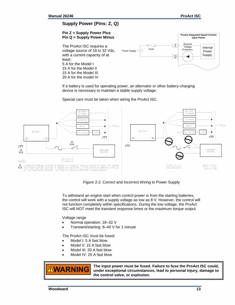
Supply Power (Pins: Z, Q) Pin Z = Supply Power Plus Pin Q = Supply Power Minus The ProAct ISC requires a voltage source of 18 to 32 Vdc, with a current capacity of at least: 5 A for the Model I 15 A for the Model II 15 A for the Model III 20 A for the model IV If a battery is used for operating power, an alternator or other battery-charging device is necessary to maintain a stable supply voltage. Special care must be taken when wiring the ProAct ISC.
Figure 2-2. Correct and Incorrect Wiring to Power Supply
To withstand an engine start when control power is from the starting batteries, the control will work with a supply voltage as low as 8 V. However, the control will not function completely within specifications. During the low voltage, the ProAct ISC will NOT meet the transient response times or the maximum torque output. Voltage range
Normal operation: 18–32 V
Transient/starting: 8–40 V for 1 minute The ProAct ISC must be fused:
Model I: 5 A fast blow
Model II: 15 A fast blow
Model III: 20 A fast blow
Model IV: 25 A fast blow
The input power must be fused. Failure to fuse the ProAct ISC could, under exceptional circumstances, lead to personal injury, damage to the control valve, or explosion.
Z
Q
FusePower Supply
ProAct Integrated Speed Control.
Input Power.
Reverse
Voltage
Protection.Internal
Power
Supply.

ProAct ISC Manual 26246
14 Woodward
Wire Requirements: For battery connections (+Bat and –Bat):
Models I and II: 1.0 mm²/16 AWG for distances up to 8 meters
Model III: 1.0 mm²/16 AWG for distances up to 5 meters
Model IV: 1.0 mm²/16 AWG for distances up to 4 meters Supply Power Specification Summary: Name Value
Min voltage normal 18 V Max voltage normal 32 V Max extended voltage 40 V (1 minute) Min extended voltage 8 V (limited performance) Max current transient Model I < 3.5 A @ 18 V Model II < 13 A @ 18 V Model III < 15 A @ 18 V Model IV < 20 A @ 18 V Max current continuous Model I <2 A @ 18 V Model II < 3.5 A @ 18 V Models III & IV < 6.5 A @ 18 V Max power steady continuous Model I - 36 W Model II - 65 W Model III - 73 W Model IV - 101 W Max power transient Model I - 67 W Model II - 251 W Model III - 282 W Model IV - 371 W EMC emissions EN 61000-6-4 EMC immunity EN 61000-6-2
MPU Input (Pins: R, S, W) Pin R = MPU plus signal Pin S = MPU min signal Pin W = Shield (shared) The MPU input detects the frequency of an MPU sensor typically pulsed by the flywheel ring gear or holes in the flywheel. The control calculates the engine speed from this MPU input signal frequency. It also provides for displaying the MPU voltage and status of the MPU input on the service tool. Connect the MPU sensor between pins R and S. Pin R is the positive input signal and pin S is for the negative input signal. The conductor shield must be connected to pin W and the other side of the MPU sensor cable is not connected and is isolated. The MPU and the RS-232 service port cables share pin W. See Woodward manual 82510, Magnetic Pickups and Proximity Switches for Electronic Controls, for information about MPUs and installation of the pickup unit.
R
S
ProAct Integrated Speed Control.
M.P.U. (Speed) input.
Edge
Voltage
Detection
W
M.P.U.
Prime Mover.

Manual 26246 ProAct ISC
Woodward 15
MPU Input Specification Summary: Name Value
Min Voltage 1 Vrms Will not detect rpm below. 0.5 Vrms Max voltage 60 Vrms Max frequency 24 kHz Min frequency 1 Hz Accuracy @ 24 kHz 1 rpm (> 3.9 sigma) Accuracy @ 20 kHz 1 rpm (> 6 sigma) Resolution clock 25 ns Max teeth 400 teeth Sample time 10 ms Number of samples Software selectable
RS-232 Service port (Pins: Y, T, X, W)
Pin Y = RS-232 TX Pin T = RS-232 RX Pin X = RS-232 Common Pin W = RS-232 Shield (shared)
The RS-232 service port is used to monitor, configure, and troubleshoot the ProAct ISC. Use a Windows operating system PC to perform these typical functions:
Monitor operations
Calibrate the position control
Tune prime mover dynamics
Load or retrieve parameter settings from the control or a file
Change a parameter setting for speed or position control
The ProAct Service Tool can be downloaded from the Internet at www.woodward.com/software/.
The minimum specification for a laptop to run the service tool is:
Windows 98, ME, NT, 2000, and XP operating systems
300 MHz Pentium CPU
64 MB RAM
800 by 600 pixel screen
Serial Port (RS-232)
It is recommended that the OEM or packager provide a breakout cable that is connected to the ProAct ISC service port and run to an easily accessible area on the engine. The service port is absolutely necessary to set up and troubleshoot the ProAct ISC.
Discrete Inputs (Pins: F, B, A, L, E)
Pin F = Discrete Input 1 Pin B = Discrete Input 2 Pin A = Discrete Input 3 Pin L = Discrete Input 4 Pin E = Discrete Input 5
DB9
Connector.
T
Y
ProAct Integrated Speed Control.
Service Port Interface.
RS232
ReceiverX
W3 52
F
BFuse
Power Supply
Used for the ISC
ProAct Integrated Speed Control.
Discrete Inputs.
Discrete
Level
detection.
A
L
E
High side switch.
Low side switch.

ProAct ISC Manual 26246
16 Woodward
The Discrete inputs are used to control the behavior of the ProAct ISC from a control panel or other control system components such as load share modules, temperature controllers, oil temperature sensors, etc. There are five Discrete inputs on the ProAct ISC control. The input functions (below) are mapped to discrete inputs using the Service Tool. If desired, multiple functions can be mapped to a single input.
The functions available for Discrete input configuration are:
Run Enable Input
Idle / Rated Input
Rated 1 / 2 Input
Raise Input
Lower Input
Alt Dynamics Input
Isoch / Droop Input
CAN ID Low Input
CAN ID High Input All five discrete inputs are the same electrical circuits. All five can be configured in the software for high side switch or low side switch and for an active closed contact or an active open contact. High Side Switch: (default) If used as a high side switch, the switch contact must be connected to the discrete input pin and to the supply plus of the ProAct ISC. The high side switch configuration is preferred. Low Side Switch: If used as a low side switch, the contact must be connected to the discrete input pin and to the power supply minus of the ProAct ISC. Active Closed: (default) Active closed can be used for situations where it is safer to make the function inactive if the wire is broken, or disconnected. Active Open : Active open contact can be used for situations where it is safer to make the function active if the wire is broken, or disconnected. The fuse shown in the diagram can be the same fuse that is used for the power supply of the ISC—there is no need for an additional fuse. Discrete Input Specification Summary: Name Value
Low Level < 4 V High Level > 7 V Hysteresis > 1 V Min Current @24 Volt > 1 mA Max Current < 10 mA Min Hardware delay > 2 ms Sample Time 10 ms Number of Samples 3 High / Low Side Switch Software Selectable Active Open / Close Software Selectable
Manual 26246 ProAct ISC
Woodward 17
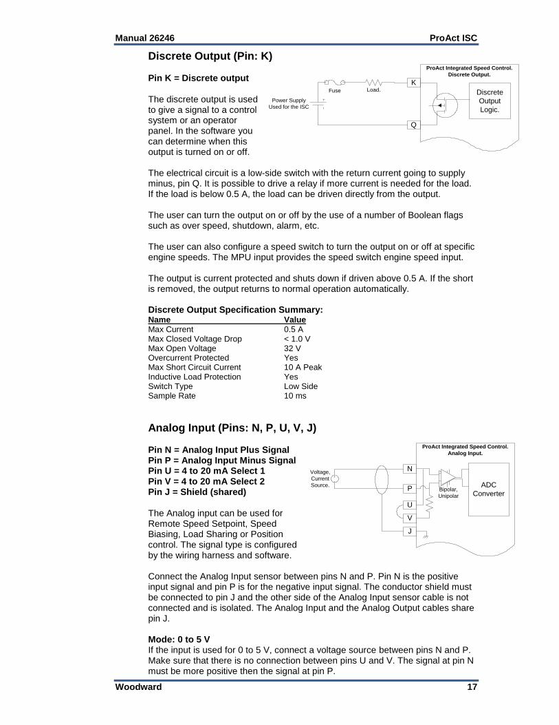
Discrete Output (Pin: K) Pin K = Discrete output The discrete output is used to give a signal to a control system or an operator panel. In the software you can determine when this output is turned on or off. The electrical circuit is a low-side switch with the return current going to supply minus, pin Q. It is possible to drive a relay if more current is needed for the load. If the load is below 0.5 A, the load can be driven directly from the output. The user can turn the output on or off by the use of a number of Boolean flags such as over speed, shutdown, alarm, etc. The user can also configure a speed switch to turn the output on or off at specific engine speeds. The MPU input provides the speed switch engine speed input. The output is current protected and shuts down if driven above 0.5 A. If the short is removed, the output returns to normal operation automatically. Discrete Output Specification Summary: Name Value
Max Current 0.5 A Max Closed Voltage Drop < 1.0 V Max Open Voltage 32 V Overcurrent Protected Yes Max Short Circuit Current 10 A Peak Inductive Load Protection Yes Switch Type Low Side Sample Rate 10 ms
Analog Input (Pins: N, P, U, V, J) Pin N = Analog Input Plus Signal Pin P = Analog Input Minus Signal Pin U = 4 to 20 mA Select 1 Pin V = 4 to 20 mA Select 2 Pin J = Shield (shared) The Analog input can be used for Remote Speed Setpoint, Speed Biasing, Load Sharing or Position control. The signal type is configured by the wiring harness and software. Connect the Analog Input sensor between pins N and P. Pin N is the positive input signal and pin P is for the negative input signal. The conductor shield must be connected to pin J and the other side of the Analog Input sensor cable is not connected and is isolated. The Analog Input and the Analog Output cables share pin J. Mode: 0 to 5 V If the input is used for 0 to 5 V, connect a voltage source between pins N and P. Make sure that there is no connection between pins U and V. The signal at pin N must be more positive then the signal at pin P.
K
Q
ProAct Integrated Speed Control.
Discrete Output.
Discrete
Output
Logic.
Fuse
Power Supply
Used for the ISC
Load.
N
P
ProAct Integrated Speed Control.
Analog Input.
ADC
Converter
J
U
V
Bipolar,
Unipolar
Voltage,
Current
Source.
ProAct Integrated Speed Control.
Analog Input.

ProAct ISC Manual 26246
18 Woodward
Mode: ±3 V If the input is used for plus and minus 3 V, connect a voltage source between pins N and P. Make sure that there is no connection between pins U and V. Pin P will be seen as the reference voltage and pin N can go positive or negative. Mode: 4 to 20 mA If the input is used for 4 to 20 mA, connect a current source between pins N and P. Make sure that pins U and V are connected as close as possible to the connector. The signal at pin N must be more positive then the signal at pin P. Analog Input Specification Summary: Name Value
Accuracy @ 20 °C 0.05 % / FS (> 6 sigma) Linearity @ 20 °C 0.5 % / FS (> 6 sigma) Resolution 12 bits (0–25 mA) (0–5 V) (–3–+3 V) Temp drift. 200 ppm/°C Sample Rate 10 ms CCM @60 Hz or lower. 60 dB CCM Voltage Range ±50 V Input Impedance (Voltage mode) 100 kΩ Input Impedance (Current mode) 200 Ω
Analog Output (Pins: H, D, J) Pin H = Analog Output Plus Signal Pin D = Analog Output Minus Signal Pin J = Shield (shared) The 4 to 20 mA analog output drives a 0 Ω to 450 Ω load. The high side (pin H) drives current from the internal power supply to the load. Connect the return current to pin D. Pin D is internally connected to the power supply ground. A shielded twisted-pair cable is recommended for the analog output. The output can be setup in the software for scaling and output type. Types supported are: the demanded position (setpoint), the actual position (feedback), and the speed input (rpm signal from the MPU). It is possible to use the analog output with more then one load if the total load resistance is not greater than 450 Ω. Analog Output Specification Summary: Name Value
Accuracy @ 20 °C 0.05 % / FS (> 6 sigma) Linearity @ 20 °C 1 % / FS (> 6 sigma) Resolution (0–25 mA) 12 bits Temperature Drift 450 ppm/°C Sample Rate 10 ms Max Load 0 Ω Min Load 450 Ω Reverse Voltage Protection Yes
H
D
ProAct Integrated Speed Control.
Analog Input.
DAC
Conversion
J
ProAct Integrated Speed Control.
Analog Output.
Load

Manual 26246 ProAct ISC
Woodward 19
CAN Port (Pins: M, G, C) Pin M = CAN High Pin G = CAN Low Pin C = Shield The CAN (Control Area Network) link is used for expansions to the control. There is currently one application determined; a J1939 CAN Position Control mode. The use of a shielded twisted-pair cable is recommended for the CAN communication. To prevent ground loops when there are more than two CAN devices on the link, the shield connection is not hard wired to the chassis. Termination is through a high-frequency capacitor. The CAN link can support 11 Bit and 29 Bit identifiers, compatible with the 2.0A and B standards. All controls on the CAN network must share the same battery minus connection between the controls. If a control is used that has an isolated output the isolated power minus signal must be connected to the battery minus of the ProAct ISC. The battery minus signal and the shield signal are not connected and therefore cannot be used as a common signal between the controls. The shield should be connected to the earth ground in the wiring harness to improve EMC performance. CAN Port Specification Summary: Name Value
Wiring Specification ISO-11898 Max Wire Length 30 m CAN Port Isolated No
M
G
ProAct Integrated Speed Control.
Analog Input.
CAN
Controller.
C
ProAct Integrated Speed Control.
CAN interface.
120 ohms
User Control
120 ohms
CAN High.
CAN Low.
CAN Common
Q

ProAct ISC Manual 26246
20 Woodward
Chapter 3. Description of Operation
General The ProAct™ ISC is an electric actuator with position feedback and an integrated digital speed control. Typically the actuator output shaft connects to the fuel gas valve, intake throttle, or fuel oil pump rack shaft of a reciprocating engine. The output shaft maximum rotation is 75 degrees and is configurable for CW or CCW rotation. A manual mode is provided to facilitate setting up the actuator system. The ProAct ISC can also be configured as a position control only for basic actuator applications. The ProAct ISC position control accepts a 4–20 mA, 0–5 Vdc, or ±3 Vdc analog or a CAN position command input signal. A PWM command input is not supported. The speed setpoint can be adjusted by a remote 4–20 mA or 0–5 Vdc analog input or by discrete inputs (such as Idle/Rated, Rated 1/Rated 2 selection, or Raise/Lower). For generator applications, isochronous load sharing and synchronizing capability are available by a ±3 Vdc analog input in place of the remote 4–20 mA / 0–5 Vdc analog input. A compatible load sharing/synchronizer device is needed to provide the load sharing/synchronizer input bias signal. Droop operation can also be configured. Control adjustments are made using the ProAct ISC Service Tool. The service tool is a Windows based software tool provided at no charge to configure, monitor, adjust, and troubleshoot a ProAct ISC speed control system. It runs on a personal computer and communicates with the ProAct ISC speed control through a serial connection. The service tool is disconnected from the control when not in service. The speed sensor input contains a tunable filter that minimizes the effects of firing torsionals, which occur normally in reciprocating engines. This filter ensures that the actuator does not react to speed sensor input changes produced by firing torsionals. This provides exceptionally smooth steady-state speed control and allows matching the control dynamics solely to the engine rather than detuning dynamics for firing torsional frequencies. The control fails to the minimum fuel position whenever the speed sensor signal is lost. The control has a switching power supply with excellent spike, ripple, and EMI (electromagnetic interference) rejection. Discrete inputs are capable of rejecting EMI and variable resistance in switch or relay contacts. Analog inputs are differential type with extra filtering for common-mode noise rejection. The control provides one discrete output, which changes state based on configurable alarms, status conditions or by a user configured speed switch. The control provides one configurable 4 to 20 mA analog output. The configuration choices are for engine speed, actuator setpoint or actuator position. This analog output may be used with an analog meter, recorder, as input to another control or to a computer.

Manual 26246 ProAct ISC
Woodward 21
The control provides one RS-232 serial interface and one CAN communication connection. The RS-232 port is the service port used by the ProAct ISC Service Tool to configure and tune the ProAct ISC system. The CAN communication is used to connect to a remote control system. Currently, the only option is for position control command input. Contact your sales representative for future software updates to the ProAct ISC.
System Operation The ProAct ISC actuator is ready for operation immediately (< 1 second) when the power supply is connected. Power may be connected to the control at the same time the engine starter motor is engaged. On an engine shutdown command, the independent engine shutdown solenoid or solenoid valve in the fuel supply should be de-activated and the power supply disconnected from the speed control. This shutdown signal should be sent directly from the engine control panel and should be independent and separate from the ProAct ISC controller.
The ProAct ISC control should not be used as the primary means of shutting down the engine.
Controller Features Description As you review the following features, keep in mind that most applications only require a few of the functions to be activated. The choices are made available to provide maximum flexibility in a single package. The user must set up the actuator direction, min and max fuel position calibration, speed input, setpoint logic, and desired I/O. From the dynamics functions area, the user can set as many or as few as is necessary for stable operation and acceptable load transient response. The user can choose all or none of the fuel limiter functions, speed setpoint modifiers, dynamic choices, alarm/shutdown functions and logic functions depending on the application. The controller I/O consists of input power, a speed input, one configurable analog input, 5 configurable discrete inputs, one configurable analog 4–20 mA output, one configurable discrete output and a CAN communication port (see Figure 1-4).
Actuator Function For Speed Control configurations, the Actuator Function converts the ProAct ISC fuel demand into a specific actuator output shaft position. Position feedback is included with the actuator function to assure positive positioning. The actuator output shaft rotation is software configured for either a clockwise (CW) or counterclockwise (CCW) output shaft rotation. For either rotation, the actuator must be forward-acting (that is, the fuel delivered to the engine must increase as the fuel demand increases). Reverse action is not supported; only reverse rotation.

ProAct ISC Manual 26246
22 Woodward
For Analog and CAN Position Control configurations, all speed control functions are disabled. In position configurations, the Actuator Function drives the ProAct ISC actuator to maintain the position commanded by the supervisory control. Position feedback is included with the actuator function to assure positive positioning. The actuator output shaft rotation is software configured for either a clockwise (CW) or counter-clockwise (CCW) output shaft rotation. An actuator correction curve is provided to configure a demanded position versus actual position for non-linear systems. The analog input can be configured to accept 4–20 mA, 0–5 Vdc, or ±3 Vdc position commands. PWM position commands are NOT supported. Only Analog or CAN.
Speed Control Functions The speed controller consists of a speed input, speed setting logic, speed modifier logic, and speed dynamics options.
Speed Input The ProAct ISC control accommodates one speed input from a magnetic speed pickup (MPU) that provides a speed signal to the control. A digital type of detection with firing torsional filtering is used for detecting engine speed. This digital detection method senses speed very quickly for rapid response to speed changes. The input frequency is converted to engine speed based on the gear teeth. The Number of Cylinders to Average setting provides filtering of the speed input.
Speed Settings and Ramps The ProAct ISC provides for local speed setpoint control by discrete raise and lower inputs. A 4–20 mA or 0–5 Vdc analog input provides for remote speed setpoint control. A ±3 Vdc analog input provides for isochronous load-sharing and synchronizer control. Input function must be configured to activate the desired setpoint function. The control also provides run, idle, and rated speed setpoints with a lower and raise limit, plus accel and decel ramps, raise and lower ramps, and a ramp to idle. All ramp rate settings are in rpm/sec, and all speed setpoint changes are ramped for smooth setpoint transition. For emergency standby applications, a very high ramp rate effectively cancels the ramp function to provide for rapid starting. The Ramp to Idle determines how fast speed is increased from run to idle speed. Accel rate determines how fast speed is increased from idle to rated speed. Decel rate determines how fast speed is decreased from rated speed to idle speed. The accel and decel rates are also used when transferring between rated 1 and rated 2 speed settings. Raise and lower rates determine how fast speed is increased or decreased by the raise and lower command inputs. Max Analog Rate determines how fast the speed can be increased or decreased by the remote speed setpoint input. The Run Speed setting must be higher than cranking speed, but below the speed attained while running on the start fuel position setting. The speed control activates at run speed by grabbing the current operating speed as the initial speed setpoint, then ramps the setpoint up to the idle speed setting at the Ramp to Idle rate. If the idle/rated input is set in the rated position, acceleration passes seamlessly through idle speed to the selected speed setpoint (rated, rated 1 or rated 2) at the accel rate or to the analog speed setpoint at the max analog rate.

Manual 26246 ProAct ISC
Woodward 23
Speed Setting Priorities The Run Speed Threshold has the highest priority and is the first speed setpoint used during engine starting. The Idle setpoint has priority over the speed bias functions (such as raise/lower, remote setpoint, load share input). The idle setpoint must be unselected (rated setpoint selected) to activate the speed bias functions. The Speed Bias functions have priority over the Rated Setpoint. For example, if the remote setpoint is selected when the idle/rated input is switched to the rated position, the setpoint will ramp to the remote setpoint rather than the rated setpoint.
Speed Setting Options The ProAct ISC has an array of options for monitoring and controlling engine speed. The applications described here are just examples as there are many more uses of the signals described.
Changing Speed Setpoint
Isoch/Droop Changing Speed Setpoint The ProAct ISC has multiple speed setpoint choices.
Rated Speed Setpoint
Idle / Rated Speed Setpoint
Rated 1 or Rated 2 Speed Setpoint
Raise/Lower Speed Modifiers
Analog Speed Modifier
Analog and Raise/Lower Speed Modifier Rated Speed Setpoint—This is used for a system where a single speed setpoint is sufficient. Speed is held constant at the rated speed setting. However, the fuel limiters, run speed setting, and accel ramp are provided and active for light-off and acceleration control up to rated speed. Typical applications are generator sets where there may be no time or need to slowly start the engine. The engine will go directly to the rated speed setpoint at the configured acceleration ramp rate. Speed modifiers may be used to synchronize and load generator sets. Idle/Rated Speed Setpoint—This feature allows the user to toggle the speed setpoint between an idle and a rated speed. An Idle/Rated discrete input, is used to toggle between the two speed settings. This input can be configured to select Rated on either opening (active open) or closing (active closed) of the contact input. The user can toggle between the two speed settings at any time during operation. During transitions, the acceleration and deceleration rates are used. Idle/Rated is commonly used to provide an idle speed setpoint for engine warm-up or cool-down cycles. The idle speed setting is independent of the lower limit setpoint and may be set at a lower speed. Idle speed cannot be changed except by adjustment of the software setpoint. During starting, the idle speed setpoint is selected when engine speed exceeds the run speed setting or while running whenever the idle/rated contact is open (assuming an active closed configuration). Closing the idle/rated contact ramps the speed setpoint from idle to rated. Closing either the raise or lower contacts while ramping from idle to rated immediately cancels the idle to rated ramp and speed follows the raise or lower commands for variable speed control. No speed setpoint adjustments (such as raise, lower, analog or droop) occur while running at idle speed.

ProAct ISC Manual 26246
24 Woodward
Rated 1 / 2 Speed Setpoint—The Rated 1 / 2 speed setpoint can be configured in two ways.
In the Startup Select Rated 1 / 2 configuration, discrete input 2 is sampled before running, and selects either the Rated 1 or Rated 2 setpoint. Typically this configuration is used to select between 50 Hz and 60 Hz operation in a generator set application. Once engine speed reaches the run speed setting, discrete input 2 has no effect until speed is below the stop speed setting.
In the Runtime Select Rated 1 / 2 configuration, discrete input 2 switches between the Rated 1 and Rated 2 setpoints while running. This configuration is typically used in a mechanical drive application where a two-step speed control system is normal.
The Idle / Rated and Runtime Select Rated 1 / 2 configurations are similar in that both offer two speed setpoints that can be selected by discrete input while running. One difference is that with the Idle / Rated configuration, no speed setpoint adjustments (such as raise, lower, and droop) are allowed during Idle operation. The idle setpoint must be unselected (rated setpoint selected) to activate the raise/lower and analog setpoints. Raise and Lower Speed Modifiers—This feature allows the user to change the speed setpoint with external discrete inputs. The raise and lower commands will not adjust the speed setpoint above the raise limit nor below the lower limit.
A lower command progressively decreases the speed setpoint down to a configured lower limit at the configured lower rate for as long as the input is in a high state (assuming the input is configured as active closed). When this input goes low, the speed reference remains fixed at the last setting reached the instant the input went low.
A raise command progressively increases the speed setpoint up to a configured raise limit at the configured raise rate for as long as the input is in a high state (assuming the input is configured as active closed). When this input goes low, the speed reference remains fixed at the last setting reached the instant the input went low.
Closing both the raise and lower discrete inputs selects the Analog Speed Modifier, if configured.
Analog Speed Modifier—This feature allows the user to alter the speed setpoint with an external signal. The input can be configured to function as a Remote Speed Setpoint or for Load Share / Sync operation. The only difference between these modes is how they affect the speed setpoint. The analog input is selected when both the raise and lower inputs are activated. In analog mode the Max Analog Rate is used to ramp analog input setpoint changes.
Remote Speed Setpoint Operation The Remote Speed Setpoint operates from 4–20 mA or 0–5 Vdc (jumper
configured). A direct or reverse acting remote speed setting can be configured, using a normal or inverted input selection. Between 4–20 mA and 0–5 Vdc, the control determines the speed setpoint based on a straight line between the configured Low limit and High limit speed settings. See Figure 3-1.

Manual 26246 ProAct ISC
Woodward 25
Figure 3-1. Remote Speed Setpoint Operation
It is recommended that the actual engine speed be used to externally verify that the speed command matches the command signal sent. Failure to comply with this recommendation can result in undetected system faults.
Load Share / Sync Operation This input provides for synchronizing and isochronous load sharing within
generator systems. A compatible isochronous load sharing /synchronizer control must be connected to provide the isochronous load sharing/synchronizer functions. This input is active only when the ProAct ISC is selected for isochronous operation.
Most Woodward Isochronous Load Sharing/Synchronizer controls operate
from –3 to + 3 Vdc. A positive voltage input increases the speed setpoint. A negative voltage input decreases the speed setpoint. At zero voltage input the speed setpoint stays constant.
The user configurable analog input must be scaled to match the Load
Sharing Module/Synchronizer used for these purposes. A DSLC™ load sharing control typically requires a 3% of rated rpm speed setpoint change per volt. An SPM-A or SPM-D synchronizer typically requires a 0.667% of rated rpm speed setpoint change per volt. Other load sharing/synchronizer controls may need different settings.
The user configurable max analog rate must be set very high (e.g. 1000
rpm/sec). The Isochronous Load Sharing/Synchronizer control must be tuned for optimum stability and load transient response.
Analog and Raise/Lower Speed Modifier—This feature allows both analog speed setpoint and raise/lower setpoint commands. When a Raise command is activated, the setpoint increases, and when a Lower command is activated, the setpoint decreases. When both the Raise and Lower inputs are activated the Analog input is selected.

ProAct ISC Manual 26246
26 Woodward
This feature is typically used in applications where the user needs manual control over the engine speed during starting and stopping or special situations. After completing the start/stop phase, or the special function, the analog input can be selected for continuous automatic control of engine speed (e.g., flow, pressure, temperature, etc.). Isoch / Droop The ProAct ISC speed control can be configured for either Isochronous speed control or droop speed control. A discrete input can be configured to switch from Isoch to Droop and back while the engine is running. Isochronous (Droop OFF)—This is the default speed modifier function. Isochronous operation maintains the engine at a constant speed setting regardless of the load it is carrying. This mode is usually preferred for engines driving compressors, pumps and for generator sets equipped with isochronous load sharing controls. For generator sets equipped with a compatible isochronous load sharing / synchronizer control, Isochronous must be configured and the analog input must be configured and connected for Load Share / Sync Operation. Droop—Droop is used to reduce the speed setpoint as the actuator position increases. This feature is primarily useful as an alternate means of loading a generator set connected to a utility bus or paralleled with another genset on an isolated bus. In this situation, the utility determines the frequency of the alternator. During droop operation, increasing the speed setpoint causes the generator to pick up load from the utility rather than increase generator frequency. Droop is occasionally used in pump or compressor applications to stabilize the engine speed. Droop is a tunable value that decreases the speed setting when load increases as determined by the actuator output position. Droop is set as a percentage of rated speed (or Hz). Actuator positions must be entered for no-load and full load to correlate the speed setting to load. A setting of 0% droop disables the Droop function. The desired engine speed reduces with the following formula:
speed reference * droop percentage * (actual position – no load actuator position)
(full load actuator position – no load actuator position)
The calculated speed offset is determined by the user-configured droop percentage, no load actuator position, and full load actuator position settings. Droop can be configured as always Off for Isochronous speed control, always On for continuous Droop operation or to be switched On and Off during operation by digital input.

Manual 26246 ProAct ISC
Woodward 27
Figure 3-2. Speed Droop
Speed Control Dynamics The control algorithms used in the ProAct ISC are designed specifically for reciprocating engine applications. The ProAct ISC speed control offers a powerful set of dynamics that closely match a wide variety of fuel delivery systems and applications. The following configuration choices are offered: Rated Dynamics If configured for Rated Dynamics, the gain remains constant as entered and does not vary with engine speed or load. These are simplest dynamics and suit most constant speed applications. Rated dynamics are typically used on engines that operate continuously at rated speed or on variable speed engines that tend to be stable at all speeds with constant dynamic settings. Idle/Rated Dynamics If configured, Idle/Rated Dynamics vary the gain with engine speed. Idle gain applies when operating at idle speed. Rated gain applies when operating at rated speed. The gain varies linearly at intermediate speeds and is limited by the idle and rated gain settings at speeds below idle and above rated. Idle/Rated dynamics are useful for variable speed engines that tend to be less stable at idle speed when using the optimum rated speed dynamic settings. Rated Dynamics Curve A Rated Dynamics Curve varies the rated gain value with fuel demand (actuator position). Fuel demand is roughly proportional to load but not necessarily in a linear manner. A 5-breakpoint gain curve is provided to map gain versus fuel demand. Gain is applied linearly between breakpoints. A common gain setting is also provided to shift all gain curve gains higher or lower. This gain curve is particularly useful for non-linear fuel systems (such as intake butterfly valves).

ProAct ISC Manual 26246
28 Woodward
Idle/Rated Dynamics Curve When using an Idle/Rated Dynamics Curve, gain varies with both engine speed and fuel demand (actuator position). Two separate 5-breakpoint gain curves are provided to map gain versus fuel demand. The Idle Gain Curve applies when the engine is operating at idle speed. The Rated Gain Curve applies when operating at rated speed. The gain varies linearly at intermediate speeds and is limited by the idle and rated gain curve settings at speeds below idle and above rated. Separate common gain settings are provided for each curve to shift all gain curve gains higher or lower. Idle/Rated Dynamics Curve is useful for non-linear fuel systems that tend to be less stable at reduced speed and load operation when using the optimum rated speed dynamic curve settings. Integral and Derivative For all dynamic configurations the Integral and Derivative settings are constant and do not vary with either engine speed or load. Dual Gain Settings Gain Window and Gain Ratio settings further modify the applied gain. These Dual Gain Dynamic settings can improve both steady state and transient load performance by automatically switching between two gain settings. A low gain setting is applied during steady-state operation. A high gain setting is applied during load transients. Dual Gain Dynamics are available for all gain configurations. During steady-state loaded operation, the control uses the primary gain setting (rated gain, idle /rated gain, etc.). In this region, gain is set to prevent the control from responding to minor speed fluctuations inherent with reciprocating engines. This essentially eliminates harmful jiggle of the actuator output and the fuel system linkage during steady-state loaded operation. During load transients, should the speed error exceed the adjustable Gain Window width, the primary gain setting is multiplied by the gain ratio setting to temporarily increase the applied gain. This higher gain produces a faster fuel response to quickly restore engine speed to the speed setting. Speed error is the difference between actual engine speed and the engine speed setting. The primary gain setting is restored once the control senses a return to steady-state operation (see Figure 3-3). Setting the gain ratio to 1 disables the function.
Figure 3-3. Control Gain as a Function of Speed Error
Manual 26246 ProAct ISC
Woodward 29
Dual Dynamics The ProAct ISC speed control provides a complete second set of dynamic adjustments (Dual Dynamics) that are selected by activating the 2nd Dynamics discrete input. The control must be configured for Dual Dynamics to make these settings available. Delay settings are available to delay switching dynamics when the 2nd Dynamics discrete input changes state. These features are particularly useful for engines where operating modes change, such as in dual-fuel or in island/parallel generator applications since they provide for better stability during mode transitions.
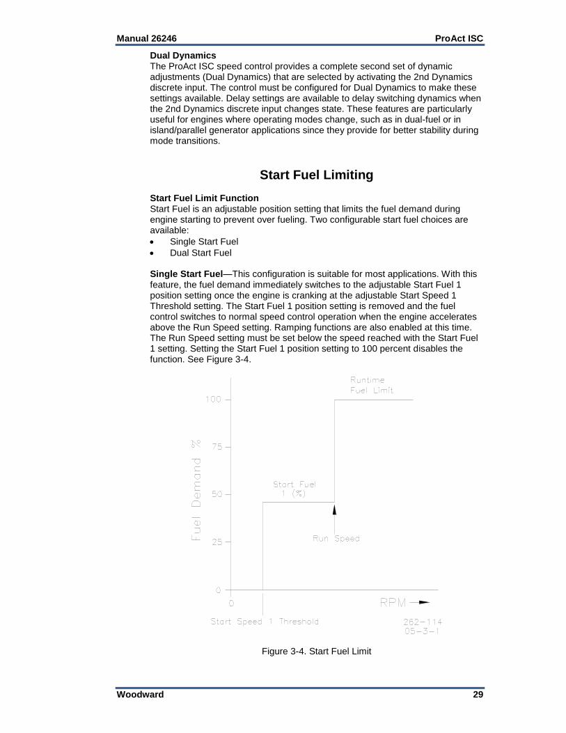
Start Fuel Limiting Start Fuel Limit Function Start Fuel is an adjustable position setting that limits the fuel demand during engine starting to prevent over fueling. Two configurable start fuel choices are available:
Single Start Fuel
Dual Start Fuel Single Start Fuel—This configuration is suitable for most applications. With this feature, the fuel demand immediately switches to the adjustable Start Fuel 1 position setting once the engine is cranking at the adjustable Start Speed 1 Threshold setting. The Start Fuel 1 position setting is removed and the fuel control switches to normal speed control operation when the engine accelerates above the Run Speed setting. Ramping functions are also enabled at this time. The Run Speed setting must be set below the speed reached with the Start Fuel 1 setting. Setting the Start Fuel 1 position setting to 100 percent disables the function. See Figure 3-4.
Figure 3-4. Start Fuel Limit
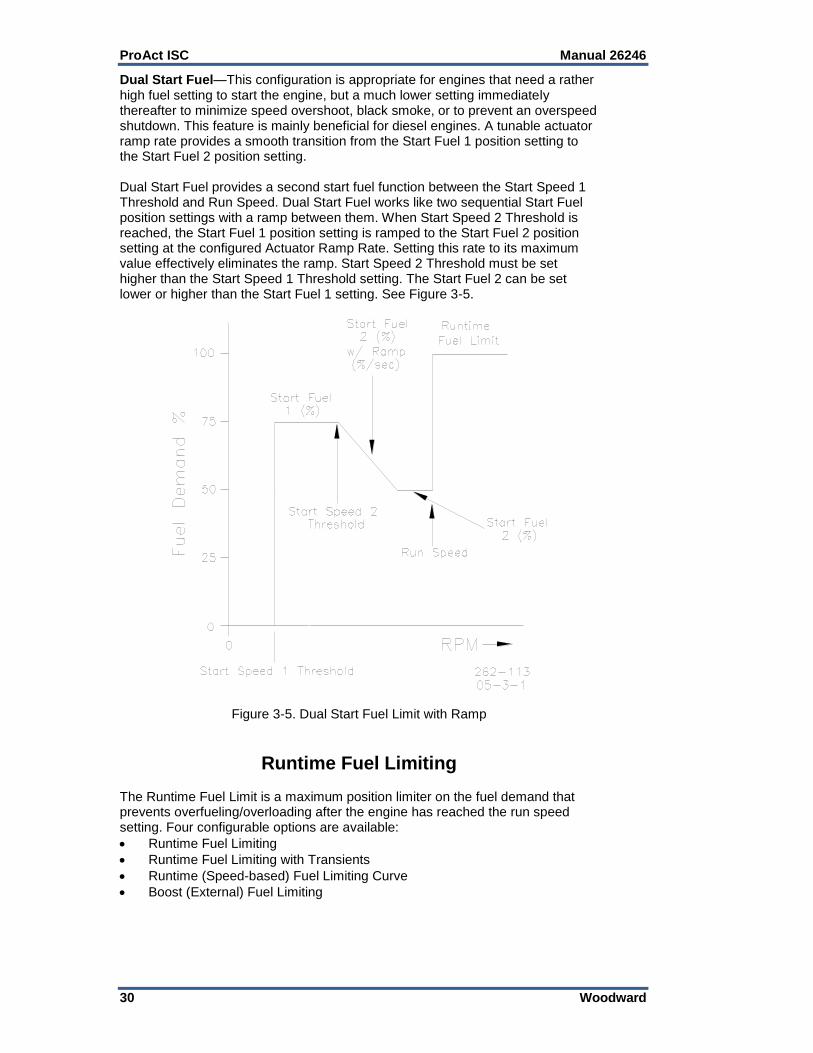
ProAct ISC Manual 26246
30 Woodward
Dual Start Fuel—This configuration is appropriate for engines that need a rather high fuel setting to start the engine, but a much lower setting immediately thereafter to minimize speed overshoot, black smoke, or to prevent an overspeed shutdown. This feature is mainly beneficial for diesel engines. A tunable actuator ramp rate provides a smooth transition from the Start Fuel 1 position setting to the Start Fuel 2 position setting. Dual Start Fuel provides a second start fuel function between the Start Speed 1 Threshold and Run Speed. Dual Start Fuel works like two sequential Start Fuel position settings with a ramp between them. When Start Speed 2 Threshold is reached, the Start Fuel 1 position setting is ramped to the Start Fuel 2 position setting at the configured Actuator Ramp Rate. Setting this rate to its maximum value effectively eliminates the ramp. Start Speed 2 Threshold must be set higher than the Start Speed 1 Threshold setting. The Start Fuel 2 can be set lower or higher than the Start Fuel 1 setting. See Figure 3-5.
Figure 3-5. Dual Start Fuel Limit with Ramp
Runtime Fuel Limiting The Runtime Fuel Limit is a maximum position limiter on the fuel demand that prevents overfueling/overloading after the engine has reached the run speed setting. Four configurable options are available:
Runtime Fuel Limiting
Runtime Fuel Limiting with Transients
Runtime (Speed-based) Fuel Limiting Curve
Boost (External) Fuel Limiting

Manual 26246 ProAct ISC
Woodward 31
Runtime Fuel Limiting The Maximum Fuel Limit setting places a runtime maximum limit on the fuel demand (actuator position). It is generally adjusted to prevent engine overloading at rated speed or to merely limit fuel delivery to the engine for other situations (such as, to prevent detonation). Adjusting the maximum fuel limit to 100 percent disables the function. Runtime Fuel Limiting with Transient The Transient Fuel Limit setting allows a temporary increase to the fuel demand above the Steady-State Fuel Limit setting for a limited time set by the Transient Fuel Limit Time setting. This permits a lower steady-state fuel limit setting while still providing an improved load-on transient response. The steady-state fuel limit is restored once the transient fuel limit time period expires. The transient fuel limit cannot be increased above 100 % fuel demand. The transient fuel limit is not active below the Run Speed setting. Runtime Fuel Limiting Curve The Runtime Fuel Limit Curve is a software adjustable five-breakpoint curve based on engine speed. The purpose of this fuel limiter is to prevent engine overload during variable speed operation by mapping a fuel limit over the entire speed operating range. The speed input provides the signal for this limiter function. A fuel demand (actuator position) limit is set at each specific engine speed breakpoint. The limiting value is linear between breakpoints as shown in Figure 3-6. The engineering units for each breakpoint are in percent and rpm. Each speed entry must be equal to or higher than the previous entry. The limiter must be carefully set since excessive fuel limiting reduces load-carrying capability. The runtime fuel limiting curve is not active below the run speed setting.
Figure 3-6. Runtime Fuel Limiting Curve

ProAct ISC Manual 26246
32 Woodward
Boost (External) Fuel Limiting The Boost Fuel Limit is a software adjustable five-breakpoint curve based on an external analog input signal. Manifold Air pressure (MAP) is typically used for the external fuel limiter signal. The purpose of the manifold air pressure fuel limiter is to prevent over fueling during loading to significantly reduce black smoke in diesel engine exhaust and unburned hydrocarbons in spark gas engine exhaust. A fuel demand (actuator position) limit is set for each specific air manifold pressure breakpoint. The limiting value is linear between breakpoints as shown in Figure 3-7. The engineering units for each breakpoint are in percent. The limiter must be carefully set since excessive fuel limiting can degrade the loading response. Occasionally exhaust temperature or other engine parameter is used for the external fuel limiting function. The external fuel limiter is not active below the run speed setting. Runtime Fuel Limiting is always active and can override a higher Boost (External) Fuel Limit setting.
Figure 3-7. Boost (External) Fuel Limit
Analog Output The analog output can be configured to show the actual position of the actuator, position setpoint for the actuator or actual speed of the engine. This can be used to connect to an engine tachometer, or to a control system for position control or diagnostics.

Manual 26246 ProAct ISC
Woodward 33
Discrete Output The discrete output can be used to show a shutdown or alarm fault condition. This can be used as a diagnostic signal for monitoring the engine. It can also be used to shut down the engine using other means separate from closing the actuator (0% position). The ProAct ISC discrete output can be configured to monitor specific parameters in the system. This can help if there is application specific trouble that must be monitored.
Temperature Sensing The ProAct ISC has an on-board temperature sensor to monitor board temperatures and protect the unit from over temperature and detect under temperature. This temperature is monitored and a fault is annunciated if temperature increases above 140 °C or falls below -45 °C.
Current Limiting based on Temperature The control provides actuator current limiting based on the electronics temperature. Dependent on board and actuator thermal models, the software reduces current as necessary to avoid conditions that would damage the device due to extreme temperatures. Current limiting based on temperature begins when the combined current and temperature environment causes board temperatures greater than 100 °C. The steady-state limit curve is a linear derate from full current at 100 °C down to zero current at 140 °C. Depending on the current (actuator torque) and ambient operating temperatures, the unit may never reach a reduced current limiting condition. See Figure 3-8.
Figure 3-8. Temperature vs. Current Limit
0
2
4
6
8
10
12
14
-50 0 50 100 150
Cu
rren
t (A
mp
s)
Temperature (deg C)
Model II Current Limits
Transient Current Limit
Steady State Current
0
5
10
15
20
25
-50 0 50 100 150
Cu
rren
t (A
mp
s)
Temperature (deg C)
Models' III, IV, and V Current Limits
Transient Current Limit
Steady State Current

ProAct ISC Manual 26246
34 Woodward
ProAct ISC Alarms and Shutdowns
Power-up Diagnostics The ProAct ISC provides power up self-test diagnostics. The power up diagnostics takes less than one second to complete. This means that the speed control is active within one second of power-up. A diagnostics error found during power-up will shut down the control. There are a limited number of power-up diagnostics, as most of the diagnostics are done during run time.
Run-time Diagnostics Once power-up tests are completed, the unit starts controlling and provides continuous indication of alarms and shutdowns. The ProAct ISC Service Tool can be used to monitor the alarm and shutdown conditions. Also, the discrete output can be configured to reflect internal shutdowns, overall alarm or shutdown status, or individual alarms and shutdowns.
Alarm and Shutdown Actions An alarm is intended to indicate a condition that an operator should be aware of during operation or troubleshooting, but does not require the engine to be shut down. Alarms are indicated on the service tool, and can be configured to annunciate on the discrete output. A shutdown means that the ProAct ISC will attempt to position the actuator at its minimum position. Depending on the cause of the shutdown, the ProAct ISC will perform one of two actions. If the shutdown cause allows the position control to still operate properly (for example, a failed speed sensor), the position controller commands the actuator to go to 0% position. If the shutdown cause does not allow the position control to operate properly (for example, a position sensor error), the actuator will be driven at the maximum steady-state current value to the minimum position mechanical stop.
Alarm and Shutdown Indications on the Service Tool Alarms and shutdowns are indicated on separate tabbed pages in the main service tool screen. See further explanation on viewing the alarms and shutdowns in the service tool by clicking on the Help menu item, then click Contents. Select “Monitoring with the service tool” in the table of contents, and click on the Viewing and Resetting Alarms and Shutdowns link. The alarm and shutdown symbols on the status bar indicate the alarm and shutdown state of the control. For example, if any alarms on the Alarm page are active, the alarm symbol on the status bar is active.
Logged Alarms and Shutdowns The occurrence of an alarm or shutdown is saved in non-volatile memory. If power to the ProAct ISC is turned off, then turned on, the logged alarm and shutdown indications can still be seen on the service tool.

Manual 26246 ProAct ISC
Woodward 35
Resetting Alarms and Shutdowns Alarm and shutdown faults can be globally set as either latching or non-latching. When set to latching, either a reset command or a power-cycle is required to clear the fault and allow the unit to start again. If non-latching, the fault is automatically cleared without any reset once the fault condition returns to normal. Alarms and shutdowns can be reset using the service tool, or by toggling the Run Enable discrete input (if connected) Off for greater than 1 second, then back to Run. If a shutdown occurs when the control is in a state other than the Engine Stopped state or Powered Down state, and then is immediately reset, the control remains shut down until the Engine Stopped state is reached.
MPU Input Diagnostics There are two diagnostics for the speed input that set the actual speed to zero rpm and flag an error whenever the engine speed is above the speed detection threshold at the time the diagnostic occurred. This threshold is defined as the start speed threshold in legacy firmware versions but was increased to the stop speed threshold in firmware version 5418-3777 B and newer. If no MPU pulses were detected for 1.6 seconds, the speed sensor is considered non-functional. As a result, engine speed will be set to zero. At low engine speed, this does a satisfactory job of detecting MPU failures. At high engine speed, however, this diagnostic is too slow. The second diagnostic detects if the time between filtered engine pulses is greater than 4 times the previous pulse. This method detects speed input signal problems earlier at higher engine speeds.
Shutdown List The following diagnostic conditions always cause a shutdown: Watchdog Reset—The software was not executing properly and the microcontroller was reset. Speed Sensor Failed—There was a sudden loss of the speed signal. Position Sensor Failed—An internal diagnostic check has determined that the actuator position sensor has failed. Overspeed—The configurable Overspeed Threshold was exceeded. Maximum Starting Time—During starting, speed did not reach the Run Speed Threshold before the Max Starting Time limit occurred. Internal Shutdown—An internal failure has occurred. The Internal Shutdowns page of the service tool indicates the exact cause.

ProAct ISC Manual 26246
36 Woodward
Configurable Alarm and Shutdown List The following diagnostic conditions can be configured as an alarm, a shutdown, or ignored (not enabled):
It is recommended that all faults be configured as shutdowns to ensure maximum fault protection.
Power-up Reset—This indication goes true when power is first applied to the ProAct ISC and remains true until reset. Analog Input High—The analog input went above the analog input Diagnostic Maximum threshold. Analog Input Low—The analog input went below the analog input Diagnostic Minimum threshold. Input Voltage High—The input supply voltage went above 33 V. Input Voltage Low—The input supply voltage went below 17 V. There is a delay time before this indication occurs, to ensure that the control does not flag a supply voltage low error during the standard engine start cycle. Electrical Temperature High—The internal electronics temperature went above 140 °C. Electrical Temperature Low—The internal electronics temperature went below –45 °C. Position Error—Indicates a difference between actual position and demanded position was detected. The magnitude and duration values are customer-configurable parameters (see Configuration, Position tab). This indication goes true when the low-pass error delay filter on the ‘expected position minus actual position’ is greater than the Error Maximum threshold setting. The filter time constant is set by the Error Delay setting. The ‘expected position’ is internally determined as the demanded position filtered by the expected dynamics. Governor High Speed—The engine speed was higher than the Governing Error High Range threshold for longer than the Governing Error High Time value. It is an indication that the speed control is no longer controlling the speed of the engine. Governor Low Speed—The engine speed was lower than the Governing Error Low Range threshold for longer than the Governing Error Low Time value. It is an indication that the speed control is no longer controlling the speed of the engine. Not Run Enabled—The Run Enabled Input is disabled or has been commanded Stop. CAN Bus Off—The CAN Bus has not been commanded On or has been commanded Off. CAN Demand Too Slow—The CAN Bus is communicating slower than the configured messages per second (msg.sec) rate. CAN Demand No Signal—The CAN Bus demand input signal is lost.

Manual 26246 ProAct ISC
Woodward 37
Chapter 4. Service Tool
Description The ProAct Service Tool software is used to configure, tune, and troubleshoot the ProAct ISC control. This chapter describes installation and use of the Service Tool. It identifies the control parameters available for viewing. Refer to Chapter 5 for comprehensive configuration instructions to set up the ProAct ISC control for customer specific applications. The Service Tool software resides on a PC (personal computer) and communicates to the ProAct ISC through connector pins T, Y, X and W (see Figure 1-4). An RS-232 breakout cable is available for purchase from Woodward, part number 1249-1147.
Engine
Control
Harness
To PC (loaded
with Service Tool)
9-Pin Straight-
Thru Cable
To ProAct
ActuatorCommunication Harness
(Woodward 1249-1147)VIS-198
2011-5-26
Figure 4-1. Communication Harness Connections
It is highly recommended that the OEM or packager provide a breakout cable for the ProAct ISC service port that is routed to a readily accessible area on the engine. The service port is absolutely needed to set up and troubleshoot the ProAct ISC.
T
YRS232
ReceiverX
W3 52
DB9
Connector
.
ProAct ISC
Service Port Interface.

ProAct ISC Manual 26246
38 Woodward
The minimum specification for a laptop to run the service tool is:
Windows 2000, XP. Vista, and 7 (32- and 64-bit) operating systems
300 MHz Pentium CPU
64 MB RAM
800 by 600 pixel screen
Serial Port (RS-232)
There is a potential for serial port damage when communicating with the ProAct ISC control. This is caused by a difference in ac voltage between neutral and earth ground. If the PC RS-232 port ground is referenced to ac neutral, and the ProAct ISC control is referenced to battery ground (ac earth ground), a large amount of current can be experienced. To avoid this situation, we strongly recommend placing an isolation transformer between the ac outlet and the PC.
Figure 4-2. Service Tool Screen Example
Getting Started
Installation Procedure The Service Tool software can be downloaded and installed from the Woodward Internet site (www.woodward.com/software/).
What to do next After the software is installed, connect a serial communications cable between the ProAct ISC breakout connection and an unused serial port on your computer. Run the Service Tool program and select the appropriate comm port. Once connected to the control, the status bar displays ‘connected’ and the Service Tool screen populates with monitor parameters.

Manual 26246 ProAct ISC
Woodward 39
An unsafe condition could occur with improper use of these software tools. Only trained personnel should have access to these tools.
Service Tool Help More help on using the Service Tool is available and included with the installation of the Service Tool product. Help can be accessed from the Service Tool ‘Contents’ drop-down selection under the Help menu located on the Main Window.
Software Version Identification The Service Tool software version is found by selecting ‘About’ under the Help menu. The control software version is identified by ‘Software Part Number’ on the Service Tool ‘Identification’ page. The Service Tool and Control must be connected to view the control information. Refer to the control software version and serial number in any correspondence with Woodward.
Monitoring the Driver
General The Service Tool has five different tabbed screens to monitor driver parameters. These are:
Overview, (see Figure 4-3)
Alarms, (see Figure 4-4)
Shutdowns, (see Figure 4-5)
Internal Shutdowns, (see Figure 4-6)
Identification, (see Figure 4-7) Displayed in an area above these screens are values showing the ProAct ISC:
Control Mode
Speed Setpoint
Actual Speed
Position Setpoint
Actual Position Control Mode Displays the state of the ProAct ISC control, the present mode of the unit. States include:
Powered Down
Engine Stopped
Stopping
Start Fuel 1
Start Fuel 2
Running Idle
Ramping
Running Rated 1
Running Rated 2
Ramping to Idle
See Appendix A for a full description of these Control Modes and the State Diagram showing the transition between control states.

ProAct ISC Manual 26246
40 Woodward
Speed Setpoint Displayed value of the speed setpoint - in rpm. Actual Speed Displayed value of the actual speed – in rpm. Position Setpoint Displayed value of the position demand - in percent. Actual Position Displayed value of the actual position - in percent.
Status Bar Indications At the bottom of the Service Tool window is a status bar. The status bar has two sections. The bottom left section displays communication status and bottom right section displays alarm & shutdown status. Communication Status This section of the status bar shows the status of communication between the service tool and the ProAct ISC control.
Connected—The Service Tool is connected to and communicating with the control.
Not Connected—The Service Tool is not connected to the control.
Connecting—The Service Tool is attempting to connect to the control. This message is displayed when Connect is selected from the Communications menu or when attempting to re-establish communication to the control. If the connection is lost, it will continuously attempt to re-connect.
Alarms and Shutdowns
Alarm Status One or more alarms on the Alarms screen are active.
Shutdown Status One or more shutdowns on the Shutdowns or Internal Shutdowns screen
are active.
Overview Screen To monitor the control parameters, go to the Overview page on the main window. This screen dynamically populates based on the ProAct ISC configuration. If a function is not programmed, it will not appear or may appear grayed out. Analog Input Displayed value of the analog input, in percent and rpm (if applicable). Discrete Inputs The overview screen displays the status of all discrete inputs. When the light is “on” then the input is active. These status lights indicate the state of the input regardless of whether the function (such as droop) is enabled or disabled. MPU Input Displayed value of the MPU input, in Vrms and Hertz, as read by the processor. Dynamics Displayed values of the actual dynamic settings used by the control. Start Fuel Limit Displayed value of the start fuel limit, in percent, as read by the processor. Connection status to the position PID is also shown.

Manual 26246 ProAct ISC
Woodward 41
Figure 4-3a. Service Tool—Overview Tab (Speed Control)
Figure 4-3b. Service Tool—Overview Tab (Position Control)

ProAct ISC Manual 26246
42 Woodward
Fuel Limit Displayed value of the runtime fuel limit, in percent, as read by the processor. Connection status to the position PID is also shown. Boost Input Displayed value of the boost input, in percent, as read by the processor. Position Controller Output Displayed value of the position controller output, in percent, as read by the processor. Estimated Current Displayed value of the estimated input current, in amps, as read by the processor. Supply Voltage Displayed value of the input power, in volts, as read by the processor. Electronics Temperature Displayed value of the electronics temperature sensor, in degrees Celsius, as read by the processor. The temperature sensor is physically located on the printed circuit board. Analog Output Displayed value of the analog output, in mA, as read by the processor. Discrete Output On/Off status of the discrete output command. The indicator is illuminated when the channel is commanded to ON and grayed-out when the command signal is OFF.
Shutdown and Alarm Indications The Shutdown and Alarm screens display the status of both active and logged fault conditions. The logged indications provide a history of events even after the unit has been power-cycled or run again. A complete listing and detailed description of all faults can be found in Chapter 3.
Indicates a logged alarm condition.
Indicates an active alarm condition.
Indicates a logged shutdown condition.
Indicates an active shutdown condition.
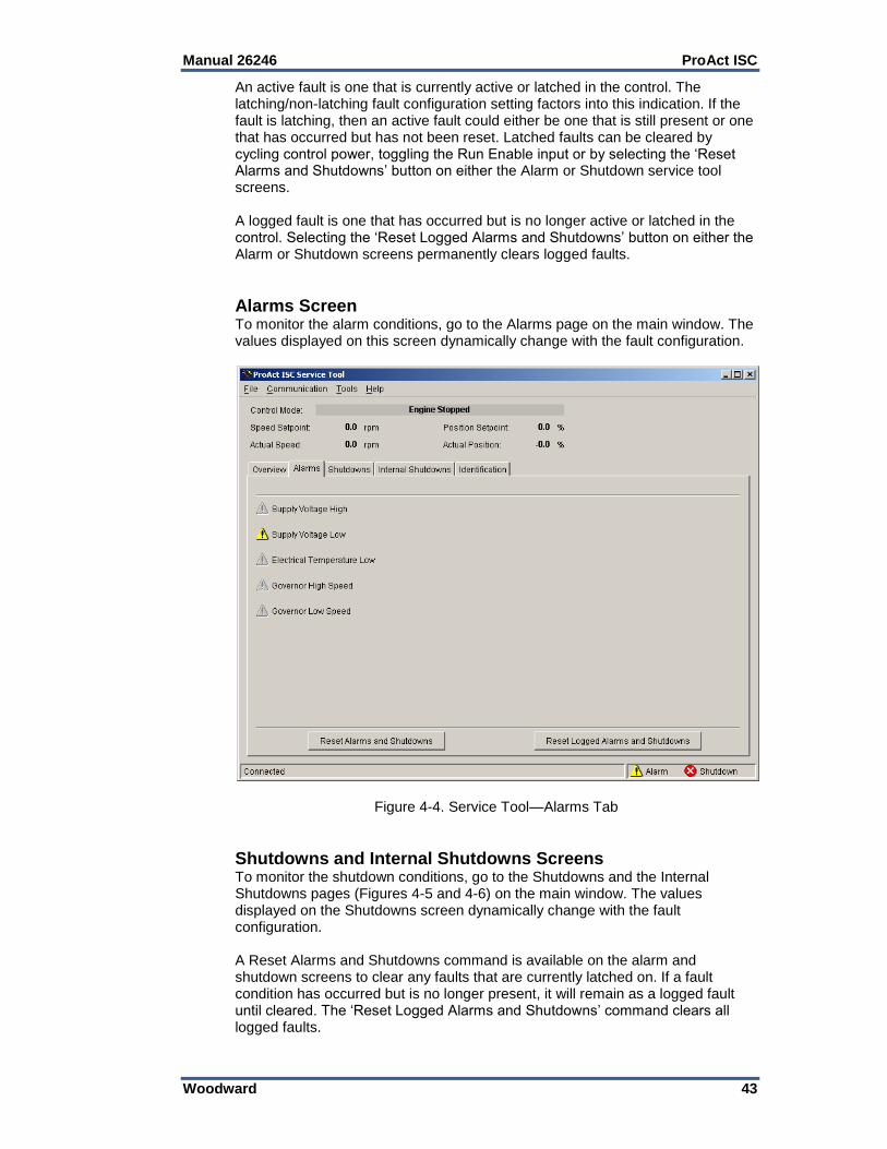
Manual 26246 ProAct ISC
Woodward 43
An active fault is one that is currently active or latched in the control. The latching/non-latching fault configuration setting factors into this indication. If the fault is latching, then an active fault could either be one that is still present or one that has occurred but has not been reset. Latched faults can be cleared by cycling control power, toggling the Run Enable input or by selecting the ‘Reset Alarms and Shutdowns’ button on either the Alarm or Shutdown service tool screens. A logged fault is one that has occurred but is no longer active or latched in the control. Selecting the ‘Reset Logged Alarms and Shutdowns’ button on either the Alarm or Shutdown screens permanently clears logged faults.
Alarms Screen To monitor the alarm conditions, go to the Alarms page on the main window. The values displayed on this screen dynamically change with the fault configuration.
Figure 4-4. Service Tool—Alarms Tab
Shutdowns and Internal Shutdowns Screens To monitor the shutdown conditions, go to the Shutdowns and the Internal Shutdowns pages (Figures 4-5 and 4-6) on the main window. The values displayed on the Shutdowns screen dynamically change with the fault configuration. A Reset Alarms and Shutdowns command is available on the alarm and shutdown screens to clear any faults that are currently latched on. If a fault condition has occurred but is no longer present, it will remain as a logged fault until cleared. The ‘Reset Logged Alarms and Shutdowns’ command clears all logged faults.
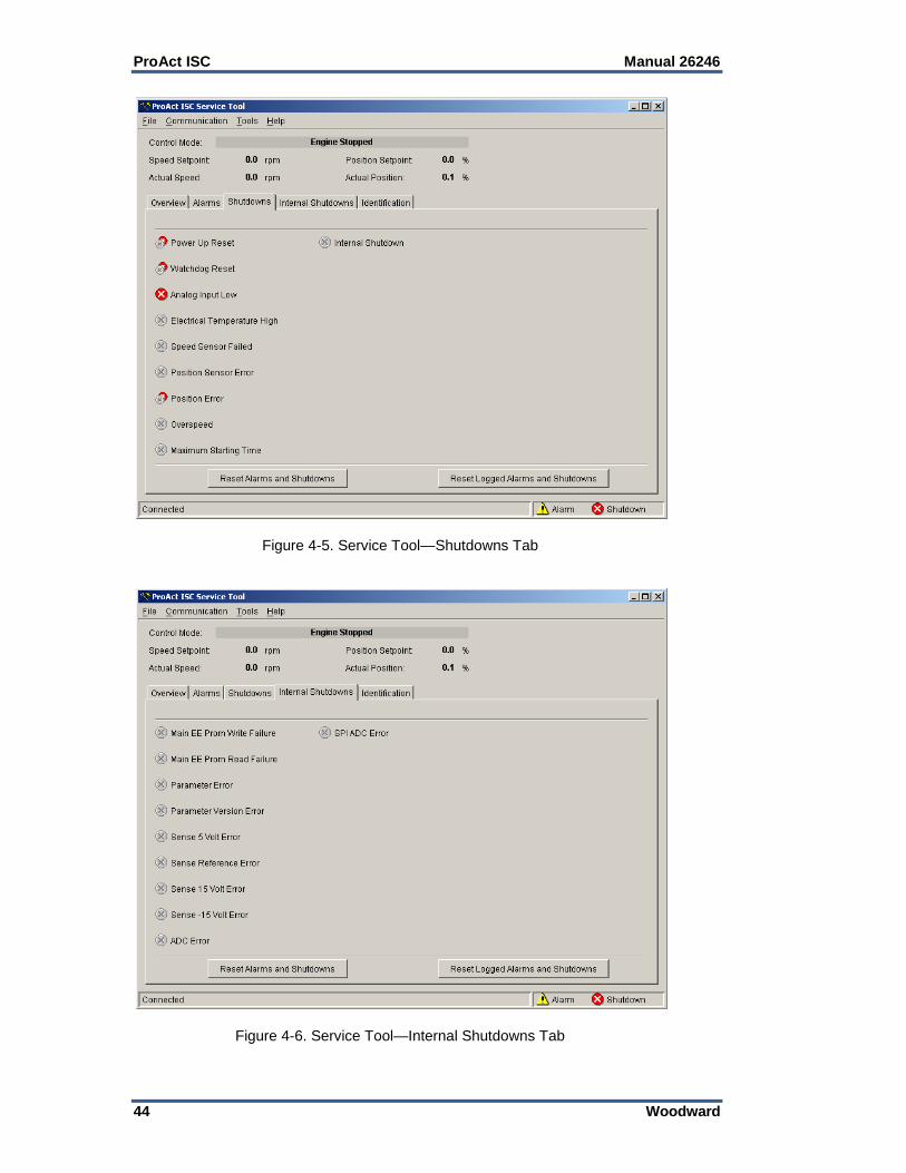
ProAct ISC Manual 26246
44 Woodward
Figure 4-5. Service Tool—Shutdowns Tab
Figure 4-6. Service Tool—Internal Shutdowns Tab

Manual 26246 ProAct ISC
Woodward 45
Identification Screen To check the ProAct ISC product identification, go to the Identification screen. Displayed information includes the ProAct ISC software part number and serial number. The Software Part Number identifies the embedded firmware part number and revision level. The Serial Number is a Woodward tracking tool set at the factory.
Figure 4-7. Service Tool—Identification Tab

ProAct ISC Manual 26246
46 Woodward
Chapter 5. Configuration
Introduction This chapter describes the general steps required to configure the ProAct ISC as a speed control on an engine or as a position control for actuator applications. Whether the ProAct ISC is configured for speed control or position control, the position controller setup is similar. The analog input or CAN input is the position demand source for position control applications. The service tool guides the user in calibrating and verifying the actuator stroke limits. Information needed to set up the ProAct ISC for speed control:
Type of engine (2 or 4 stroke)
Number of cylinders for MPU input filtering
Number of gear teeth on the engine where the speed input is sensed
Idle Speed
Rated Speed
Overspeed threshold
Max accel rate allowed from idle to rated speed
Max accel rate allowed from starting to idle There are three steps in setting up the ProAct ISC for speed control:
Setup of the position controller
Setup of the speed controller
Setup of auxiliary signals
Overview The ProAct ISC Service Tool is used to configure and adjust the settings within the ProAct ISC. Refer to Chapter 4 for Service Tool installation and connection instructions. The existing ProAct ISC control configuration settings can be viewed at any time when connected to the control by opening the Configuration Editor (File/Open Control Configuration). The ProAct ISC can be configured either on-line or off-line. On-line configuration can only be performed when the Service Tool is connected to and communicating with the ProAct ISC control. Off-line configuration can be done at any time; however, settings do not take effect until they are loaded into the control.
The engine, turbine, or other type of prime mover should be equipped with an overspeed shutdown device to protect against runaway or damage to the prime mover with possible personal injury, loss of life, or property damage.
The overspeed shutdown device must be totally independent of the prime mover control system. An overtemperature or overpressure shutdown device may also be needed for safety, as appropriate.
An unsafe condition could occur with improper use of these software tools. Only trained personnel should have access to these tools.

Manual 26246 ProAct ISC
Woodward 47
Configuring the Unit—On-Line Unit On-Line configuration is summarized as follows: 1. Open the Configuration Editor Dialog by selecting ‘File/Open Control
Configuration’. 2. Edit the configuration settings. 3. Load the configuration to the ProAct ISC control.
As changes are made to Configuration parameters, the driver does not use them until a ‘load’ command is issued. Selecting the ‘Cancel’ button closes the Configuration Editor and does not make any changes to the driver.
Configuring the Unit—Off-Line Unit Off-Line configuration is summarized as follows: 1. Open the Configuration Editor Dialog using the ‘File/New Configuration’ or
‘File/Open Configuration File’ 2. Edit the configuration settings. 3. Save the configuration to a file. At a later date simply open the configuration
and load it into the control.
Configuration Parameters There are 10 different screens that display the configuration settings in the ProAct ISC speed control: Setpoint, Control, MPU Input, Modifiers, Fuel Limiting, Dynamics, Analog I/O, Discrete I/O, Alarm/Shutdown, and Position. There are two overall control type settings.
Control Type Setting The Control Type setting determines whether the ProAct ISC functions as a Speed Control or as an Analog or CAN Position Control (actuator only). This setting also determines the display of additional configuration parameters. Configuration settings are limited to those valid for the selected control type. Speed Control This selection sets the ProAct ISC to function as a Speed Control. Analog Position Control This selection sets the ProAct ISC to function as an Analog Position Control. CAN Position Control This selection sets the ProAct ISC to function as a CAN Position Control.

ProAct ISC Manual 26246
48 Woodward
Setpoint Tab The setpoint tab provides the speed setpoint configuration settings.
Speed Setpoint Mode The Mode determines how the speed setpoint functions. This setting also affects the display of other configuration parameters. Rated—Single speed setpoint control—at rated speed. Idle / Rated—Two speed setpoint control, idle and rated. Must configure an
Idle/Rated discrete input to provide this function. Start-up Select Rated 1/2—Setpoint uses 2 rated speeds, selected on unit
start-up. Must configure a Rated 1/2 discrete input to provide this function. Runtime Select Rated 1/2—Setpoint uses 2 rated speeds, selectable at
any time. Must configure a Rated 1/2 discrete input to provide this function. Idle / Rated 1 / Rated 2—Setpoint uses idle and 2 rated speeds, selectable
at any time. Must configure an Idle/Rated and a Rated 1/2 discrete input to provide these functions.
Idle / Rated Input—Select the desired discrete input for the Idle/Rated function.
Rated 1/2 Input—Select the desired discrete input for the Rated 1/2 function.
Idle Setpoint Sets the Idle Setpoint. Only displayed if Idle is used. Allowed values: 0–4000 rpm, but must be less than Rated. Rated Setpoint Sets the Rated Setpoint. Only displayed if Rated is used. Allowed values: 0–4000 rpm, but must be greater than Idle. Rated 1 Setpoint Sets the Rated 1 Setpoint. Only displayed if Rated 1 is used. Allowed values: 0–4000 rpm, but must be greater than Idle.

Manual 26246 ProAct ISC
Woodward 49
Rated 2 Setpoint Sets the Rated 2 Setpoint. Only displayed if Rated 2 is used. Allowed values: 0–4000 rpm, but must be greater than Idle. Acceleration Ramp Rate Setpoint ramp rate, in rpm/sec, used when increasing to a rated setpoint. Allowed values: 0.1–1000 rpm/s. Deceleration Ramp Rate Setpoint ramp rate, in rpm/sec, used when decreasing to a rated or idle setpoint. Allowed values: 0.1–1000 rpm/s. Ramp to Idle Check to use the Ramp Rate to Idle. Leave unchecked to immediately raise the speed setting to the Idle Setpoint as soon as the Run Speed Threshold is reached. Ramp Rate to Idle Setpoint ramp rate, in rpm/sec, used when idle speed is selected. Only displayed if Idle is used. Allowed values: 0.1–1000 rpm/s.
Control Tab The control tab provides engine start and stop configuration settings.

ProAct ISC Manual 26246
50 Woodward
The ProAct ISC speed settings must abide by the following general order.
Starting the Engine A typical engine starting sequence looks like this, if no shutdown faults are detected: 1. When powered-up, the ProAct ISC control is in position control at the
configured min position. 2. If a Run Enable discrete input is configured, it must be enabled to start. 3. When the starter is engaged, the speed increases above the Start Speed 1
Threshold, and the controller positions the shaft to the Start Fuel 1 position demand.
4. If two Start Fuel positions are used and speed increases above the Start Speed 2 Threshold, the controller positions the shaft to the Start Fuel 2 position demand.
5. Once the engine speed is above the Run Speed Threshold, the controller switches from the start fuel position demand to the speed controller PID position fuel demand.
At this point, the unit is in speed control and controls engine speed at the selected speed setpoint (Idle, Rated, Rated 1, or Rated 2). Setpoint ramping is always active during speed control to ramp between setpoints. The PID position is tracking the start fuel values during starting to provide a bumpless transfer from start fuel control into speed control. If a shutdown fault is detected, the control will drive the output to the calibrated fail direction position.
Engine Starting Settings Run Enable Input Select the desired discrete input for the Run Enable function. Start Fuel Set to either one start fuel setting or 2 start fuel settings with a ramp between the settings. A single start fuel is suitable for most applications. With this configuration, the fuel demand immediately switches to the Start Fuel 1 setting when the engine speed has exceeded the Start1 Speed setting. Dual start fuel configuration is appropriate for engines that need a rather high fuel setting to start the engine, but a much lower setting immediately thereafter to minimize speed overshoot, minimize black smoke, or to prevent an overspeed shutdown.

Manual 26246 ProAct ISC
Woodward 51
Start Speed 1 Threshold Start Speed 1 Threshold is set below cranking speed. Once this threshold is exceeded, the control determines a start is in progress and opens the actuator to the start fuel setting. At this point the governor state changes from ‘Stopped’ to ‘Start Fuel 1’. Typical value is 20 rpm to detect engine cranking. Allowed values: 0–4000 but must be less than ‘Start Speed 2 Threshold’ (if used) and less than the ‘Stop Speed Threshold’. Start Speed Hysteresis While in the Start Fuel State, hysteresis ensures that normal variation of engine speed during cranking does not cause the control to drop back into the Stopping state. Once the control reaches the Start Fuel state, it will enter the Stopping state when engine speed drops below the (Start Speed 1 Threshold – Start Speed Hysteresis) value. Allowed values: 0 to ‘Start Speed 1 Threshold’. Start Fuel 1 Specifies the output shaft position when the governor state is ‘Start Fuel 1’. Value is set to provide proper throttle or valve position for reliable starting. Allowed values: 0–100% Start Speed 2 Threshold Specifies the speed at which the Governor State changes from ‘Start Fuel 1’ to ‘Start Fuel 2’ Typical value is 50% of the lowest speed reference. Only displayed if two start fuel limits are configured. Allowed values: Must be between ‘Start Speed 1 Threshold’ and the ‘Stop Speed Threshold’. Start Fuel 2 Specifies the output shaft position when the governor state is ‘Start Fuel 2’. Only displayed if two start fuel limits are configured. Allowed values: 0–100% Actuator Ramp Rate Specifies the rate, in %/s, the control will move the actuator position from the Start Fuel 1 to the Start Fuel 2 position once the speed exceeds the Start Speed 2 Threshold. If the ramp rate is set to its maximum value, the change to the second start fuel setting is nearly instantaneous, essentially eliminating the ramp feature. Only displayed if two start fuel limits are configured. Allowed values: 0.1 to 1000%/s Max Starting Time This is the maximum time the engine is allowed to stay within the Start Fuel state. This is used to make sure that if there is a problem starting the engine, the engine will be stopped after a reasonable amount of time. Allowed values: 0–600 s Run Speed Threshold Specifies the speed at which the Governor State changes from ‘Start Fuel’ to ‘Run’. Typical value is 80% of the lowest speed reference. Setting must be above cranking speed but below the speed achieved with the start fuel setting (light-off speed). When the engine speed is above the Run Speed Threshold, the control switches to one of the running states and begin using the speed control to drive the actuator position demand.

ProAct ISC Manual 26246
52 Woodward
Allowed values: Must be greater than ‘Stop Speed Threshold’ and less than 4000.
Engine Stopping Settings Power Down Time Specifies the time the control remains in position control after the engine is stopped and the run enable input is made inactive. Once in the Power Down state, the control applies the Power Down Holding Current to the actuator. Allowed values: 0–600 s Power Down Holding Current In the stopped state the control drives the actuator closed with the Stopped State Holding Current. This is a percent value of steady state current of the actuator. This acts like a return spring (electrical return spring) if the power to the actuator is still available. This helps with diesel pump application or throttle application where it is important to keep the actuator at the closed position while the engine is stopped. Allowed values: 0–100% Steady state current and Torque of the actuators are: Model I steady state current 3 A Model I steady state torque 1.3 Nm (11.5 lb-in) Model II steady state current 6 A Model II steady state torque 2.6 Nm (23 lb-in) Model III steady state current 10 A Model III steady state torque 5.2 Nm (46 lb-in) Model IV steady state current 10 A Model IV steady state torque 10.4 Nm (92 lb-in) The nominal torque produced by the actuator will be:
TorqueStateSteadyCurrentStateSteady
CurrentActuatorTorqueClosing
where the actuator current is
CurrentStateSteadyCurrentActuatorCurrentHoldingDownPower
100
%
To determine the current draw from the battery in this holding mode, use this formula:
VoltageBattery
CurrentActuatorrentBatteryCur
2)(2.18.0
This is the nominal calculation at a battery voltage of 27 V. Depending on temperature; the battery current can be different.

Manual 26246 ProAct ISC
Woodward 53
Stop Speed Threshold Specifies the speed at which the Governor State changes from ‘Stopping’ to ‘Stopped’. If the engine is stopped by a shutdown, the control will go to the Stopping state and the engine must stop before proceeding to any other state. If the engine is stopped by the Run Enable input, the control will again go to the Stopping state. In this case, however, if engine speed is still above the Stop Speed Threshold, making the Run Enable switch active again will allow the control to go directly back to the running state. Below the Stop Speed Threshold, the control does not allow the engine to go directly back to the running state. Allowed values: Must be greater than the ‘Start Speed Threshold’ and less than ‘Run Speed Threshold’. Stop State Delay The Stopped State Delay setting delays the change from the Stopping state to the Engine Stopped state (where the engine can be started again). This is done to prevent starting the engine when it is still turning and the speed input has failed. This time should be set to the time it takes the engine to come to a full stop from the Start Speed 1 Threshold. Above the Start Speed 1 Threshold, the speed signal loss results in a speed sensor failure, and the engine will not restart until the control is reset. Allowed values: 0–600 s
Error Detection Settings Governing Error Low Range Maximum error setting that triggers a Governing Error Low fault. Allowed values: 0–4000 rpm Governing Error Low Time Governing Error Low speed range persistence, in seconds, prior to indicating a fault. Allowed values: 0–600 s Governing Error High Range Maximum error setting that triggers a Governing Error High fault. Allowed values: 0–4000 rpm Governing Error High Time Governing Error High speed range persistence, in seconds, prior to indicating a fault. Allowed values: 0–600 s Overspeed Threshold Specifies the speed level that triggers an overspeed shutdown fault. Allowed values: 0–4000 rpm, but must be greater than Rated.

ProAct ISC Manual 26246
54 Woodward
MPU Input Tab The MPU Input tab provides the speed input configuration settings.
The MPU must be configured to ensure the control reads the correct engine speed. A dangerous situation could result from incorrect MPU input configuration since the ProAct ISC would sense speed incorrectly and therefore not control the speed correctly. Also, the internal ProAct ISC overspeed protection does not work properly if the MPU input is incorrectly configured.
MPU Input Settings 2-Cycle Specifies using the speed-sensing algorithm for a 2-cycle engine. 4-Cycle Specifies using the speed-sensing algorithm for a 4-cycle engine Number of Cylinders Sets the number of engine cylinders. Allowed values: 1—20 Number of Cylinders Averaged Sets the number of cylinders to be averaged by the speed-sensing algorithm. This setting is used as a filter to minimize the effects of firing torsionals that occur normally in reciprocating engines. A lower value gives less filtering, increases steady-state speed variation but allows for better transient response. A higher value reduces steady-state speed variation but slows transient response.

Manual 26246 ProAct ISC
Woodward 55
If unsure, set this to either ‘1’ or half the ‘Number of Cylinders’ for a 4-stroke. On a 2-stroke engine, ‘1’ or ‘Number of Cylinders’ are good choices. For uneven firing patterns, ‘Number of Cylinders Averaged’ should be set to eliminate repeating torsionals. Allowed values: 1 to ‘Number of Cylinders’. Number of Teeth per Engine Revolution Sets the number of teeth seen by the speed sensor during one engine revolution. This value is used to calculate the engine speed based on MPU frequency. Allowed values: 0.5–400.
Modifier Tab The modifiers tab provides droop and speed setpoint biasing configuration settings.
Droop Settings
Droop Mode Determines what methods of adjustment of the speed setpoint are to be allowed. Off–no droop is used, unit to remain in isochronous speed control. On–actuator position droop is always enabled and active above Idle speed. Digital Input–actuator position droop is enabled based on the droop
discrete input. If this is selected, a digital input must be configured for this function

ProAct ISC Manual 26246
56 Woodward
Isoch/Droop Input Select the desired discrete input for the Isoch/Droop function. Droop Sets the percentage of actuator position droop when droop is enabled. Allowed values: 0–100% No Load Sets the no-load actuator position percentage for the droop function. Below this actuator position the droop is zero. Allowed values: 0% up to the ‘Full Load’ setting Full Load Sets the full load actuator position percentage for the droop function. Allowed values: From the ‘No Load’ setting up to 100%
Bias Settings Bias Mode Determines which adjustment methods of the speed setpoint are to be allowed. None–no biasing of the speed setpoint is used. Raise/Lower–raise and lower setpoint adjustment commands are used.
Must configure raise and lower discrete I/O points to provide this function. Analog–analog biasing of the speed setpoint is used. Analog or Raise/Lower–a combination of raise/lower and analog biasing
are used to adjust the speed setpoint. Must configure raise and lower discrete I/O points to provide this function.
Max Analog Rate Specifies the maximum ramping rates allowed for the speed setpoint Analog adjust function. Only displayed if Analog is configured. Allowed values: 1–1000 rpm/s
It is recommended the Max Analog Rate setting be set to a value that will prevent overshoot and possible overspeed on enabling of the Remote Input.
Raise Input Select the desired discrete input for the raise speed function. Lower Input Select the desired discrete input for the lower speed function. Lower Rate Specifies the ramping rate for the speed setpoint Lower function. Only displayed if the Raise/Lower function is configured. Allowed values: 0.1–1000 rpm/s Raise Rate Specifies the ramping rate for the speed setpoint Raise function. Only displayed if the Raise/Lower function is configured.

Manual 26246 ProAct ISC
Woodward 57
Allowed values: 0.1–1000 rpm/s Analog Operational Mode Determines how the analog input range is applied to the speed setpoint. Load Share / Sync Operation–biasing is based on a percentage band
around the speed setpoint. Remote Speed Setpoint–biasing values are set to a specific speed range. Bias Limit Specifies the maximum desired speed band possible, as a percentage of Rated, with the Raise/Lower Adjust or Analog functions. Allowed values: 0–100% of speed setpoint Low Limit Specifies the lowest desired speed setpoint possible with the Raise/Lower Adjust or Analog functions. Allowed values: From zero rpm to the ‘High Limit’. High Limit Specifies the highest desired speed setpoint possible with the Raise/Lower Adjust or Analog functions. Allowed values: From the ‘Low Limit’ up to 4000 rpm.
Fuel Limiting Tab The fuel limiting tab provides run time fuel limiting configuration settings. If both the runtime fuel limit and the boost fuel limit are configured, the Fuel Limit is the lower of the two.

ProAct ISC Manual 26246
58 Woodward
Fuel Limiting Settings Runtime Fuel Limiting Determines the runtime fuel limiting mode. None–No fuel limiters are used. Runtime Fuel Limiting–a max actuator position is used to limit commanded
fuel position. Runtime Fuel Limiting with Transients–a steady state and a transient fuel
limit is used. Runtime Fuel Limiting Curve–a speed-based curve is used to determine
the fuel limit percentage. Boost Fuel Limiting–an analog input, boost-based curve is used to
determine the fuel limit percentage. Boost Fuel Limiting Determines whether the boost fuel limit curve is used to limit the fuel based on boost pressure or not. Maximum Fuel Limit Sets the maximum permitted shaft position. Only displayed if the mode is set to either Runtime Fuel Limiting or Boost Fuel Limiting Curve. Allowed values: 0–100% Steady State Fuel Limit Sets the maximum permitted actuator commanded position during steady state conditions. Only displayed if the mode is set to Runtime Fuel Limiting with Transients. Allowed values: 0–100% Transient Fuel Limit Sets the maximum actuator position during a transient where the fuel demand is above the Steady State Fuel Limit. Only displayed if the mode is set to Runtime Fuel Limiting with Transients. Allowed values: 0–100% Transient Fuel Limit Time Determines the length of time the Transient Fuel Limit is applied during a transient. Only displayed if the mode is set to Runtime Fuel Limiting with Transients. Allowed values: 0–600 s Speed (rpm) Allowed values: Each breakpoint [5] must be larger than the previous and less than the next value. Limit (%) Sets the maximum actuator positions for each breakpoint [5] based on the current speed. Allowed values: 0–100% Boost (%) Allowed values: Each breakpoint [5] must be larger than the previous and less than the next value.

Manual 26246 ProAct ISC
Woodward 59
Limit (%) Sets the maximum actuator positions for each breakpoint [5] based on the boost analog input. Allowed values: 0–100%
Dynamics Tab The dynamics tab provides speed control dynamic settings. The dynamic settings can also be adjusted from the Edit Speed Dynamics screen during runtime.
Dynamics Settings Overall Mode Set to Single, Dual or Dual with Delay dynamics. Alt Dynamics Input Select the desired discrete input for the alternate dynamics function. Only available when Dual Dynamics is selected. Delay Switch (between Dyn 1 and Dyn 2) The delay, in seconds, before the dynamics actually changes to the selected set (either from dynamics 1 to dynamics 2 or vice versa). Allowed values: 0–600 sec Mode (Dynamics 1 and 2) Sets the functional mode for the P-gain term of the PID. This can be individually set for both sets of dynamics, if used.

ProAct ISC Manual 26246
60 Woodward
Rated–a single speed gain term is used which remains constant and does not vary with engine speed or load. These are simple dynamics that suit most constant speed applications. Rated dynamics are typically used on engines that operate continuously at rated speed or on variable speed engines that tend to be stable at all speeds with constant dynamic settings.
Idle Rated–the gain term is changed linearly between Idle and Rated
speed. Idle gain applies when operating at idle speed. Rated gain applies when operating at rated speed. The gain varies linearly between the two settings at intermediate speeds and is limited by the idle and rated gain setting at speeds below idle and above rated. Idle/Rated dynamics are useful for variable speed engines that tend to be less stable at idle speed with optimum rated speed dynamic settings. Must configure an Idle/Rated discrete input to provide this function (see Setpoint tab).
Rated Curve–the gain term is adjusted based on actuator position using a
5-pt curve. Fuel demand is roughly proportional to load but not necessarily in a linear manner. A 5-breakpoint gain curve is provided to map gain versus fuel demand. Gain is applied linearly between breakpoints. A common gain setting is also provided to shift all gain curve gains higher or lower. This gain curve is particularly useful for non-linear fuel systems (for example, intake butterfly valves).
Idle Rated Curve–the gain is adjusted by using both actuator position and
speed. Must configure an Idle/Rated discrete input to provide this function (see Setpoint tab).
Selection of Dynamics 2 curve options is only allowed if Dynamics 1 is also set to a curve option.
Integral Speed control PID integral term in repeats per second. Allowed values: 0–10 1/sec Derivative Speed control PID derivative term in seconds. Allowed values: 0–5 sec Gain Window Speed control PID gain window, in rpm. When the speed error is greater than the window, the Gain is multiplied by the Gain Ratio. Allowed values: 0–4000 rpm Gain Ratio Speed control PID gain ratio. When the speed error is greater than the window, the Gain is multiplied by the Gain Ratio. To disable the dual gain window, set the Gain Ratio to 1. Allowed values: 1–10 Rated Gain Speed control PID gain term. This setting is applicable at rated speed. Allowed values: 0.01–10 %/rpm

Manual 26246 ProAct ISC
Woodward 61
Idle Gain Speed control PID gain term. This setting is applicable at idle speed. Intermediate gain settings apply at intermediate speeds between rated and idle.
Allowed values: 0.01–10 %/rpm
Position (%) Position breakpoints for the gain curve.
Allowed values: Each point [5] must be larger than the previous and less than the next value.
Range: 0–100%
Gain (%/rpm) Sets the gain value [5] based on the position.
Allowed values: 0.01–10 %/rpm
Common Gain Speed control PID common gain. This setting is a multiplier on the entire gain curve settings. A Common Gain setting of 1 provides no bias for the curve settings.
Allowed values: 0.01–10
Analog I/O Tab
The Analog I/O tab provides analog input and analog output configuration settings. When the ProAct ISC control type is configured for analog position control, the analog input is the position demand source. When configured for speed control, the analog input may be configured as a speed modifier or as a boost fuel limiter input. When configured for CAN position control, the analog input is not available for use.

ProAct ISC Manual 26246
62 Woodward
Analog Input Selection The analog input is scaled from input volts or mA to output %. It can be configured as follows: None–The analog input is ignored and does not affect the operation of the
ProAct ISC. 0–5 Volts–The analog input is a voltage input used as a remote speed
setpoint bias or as a boost fuel limit input or when configured, as the position control command signal.
4–20 mA–The analog input is a current input used as a remote speed setpoint bias or as a boost fuel limit input or when configured, as the position control command signal.
±3 Volts–The analog input is a bipolar voltage input used for synchronizing or load sharing.
Voltage Minimum Specifies the lowest voltage used for the analog input voltage to the output minimum percent scaling. Allowed values: 0–5 Vdc Voltage Maximum Specifies the highest voltage used for the analog input voltage to the output maximum percent scaling. Allowed values: 0–5 Vdc Current Minimum Specifies the lowest current used for the analog input current to the output minimum percent scaling. Allowed values: 0–25 mA Current Maximum Specifies the highest current used for the analog input current to the output maximum percent scaling. Allowed values: 0–25 mA Output Minimum Specifies the lowest output percent used for the output minimum percent to the analog input minimum voltage or current scaling. Allowed values: 0–100 % Output Maximum Specifies the highest output percent used for the output maximum percent to the analog input maximum voltage or current scaling. Allowed values: 0–100 % Diagnostic Minimum Specifies the minimum normal value for the analog input. When configured, an Analog Input Low alarm or shutdown fault is triggered when the input falls below this setting. Allowed values: -1 to 6 V or 0-25 mA

Manual 26246 ProAct ISC
Woodward 63
Diagnostic Maximum Specifies the maximum normal value for the analog input. When configured, an Analog Input High alarm or shutdown fault is triggered when the input increases above this setting. Allowed values: -1 to 6 V or 0-25 mA
The user should ensure that the Diagnostic Minimum and Diagnostic Maximum fields are set to values that will trigger an alarm or shutdown when reasonable faults such as open or shorted wires occur.
Analog Output Selection The analog output is scaled from the position percent (actual % or setpoint%) or the actual speed (rpm) to provide a current output from the ProAct ISC. It can be configured as follows: None–The analog output is turned off. Actual Position–Sets the analog output to be an actual position output
signal. Position Setpoint–Sets the analog output to be a position setpoint output
signal. Actual Speed–Sets the analog output to be an actual speed output signal.
This selection is not available when configured for Analog Position Control. Position Minimum Specifies the lowest position % used for the analog output position percent to output current minimum scaling. Setting the position minimum % higher than the position maximum % is allowed to provide for a reverse acting signal as needed. Allowed values: 0–100% Position Maximum Specifies the highest position % used for the analog output position percent to output current maximum scaling. Allowed values: 0–100% Speed Minimum Specifies the lowest speed used for the analog output speed to output minimum current scaling. Setting a speed minimum rpm higher than the speed maximum rpm is allowed to provide for a reverse acting signal as needed. Allowed values: 0–4000 rpm Speed Maximum Specifies the highest speed used for the analog output speed to output maximum current scaling. Allowed values: 0–4000 rpm Output Current Minimum Specifies the lowest output current used for the analog output current to position minimum % or speed minimum rpm scaling.
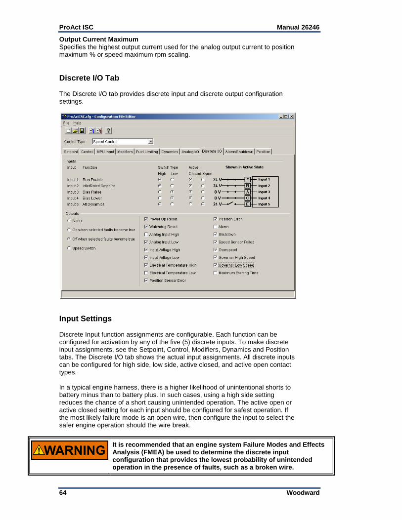
ProAct ISC Manual 26246
64 Woodward
Output Current Maximum Specifies the highest output current used for the analog output current to position maximum % or speed maximum rpm scaling.
Discrete I/O Tab The Discrete I/O tab provides discrete input and discrete output configuration settings.
Input Settings Discrete Input function assignments are configurable. Each function can be configured for activation by any of the five (5) discrete inputs. To make discrete input assignments, see the Setpoint, Control, Modifiers, Dynamics and Position tabs. The Discrete I/O tab shows the actual input assignments. All discrete inputs can be configured for high side, low side, active closed, and active open contact types. In a typical engine harness, there is a higher likelihood of unintentional shorts to battery minus than to battery plus. In such cases, using a high side setting reduces the chance of a short causing unintended operation. The active open or active closed setting for each input should be configured for safest operation. If the most likely failure mode is an open wire, then configure the input to select the safer engine operation should the wire break.
It is recommended that an engine system Failure Modes and Effects Analysis (FMEA) be used to determine the discrete input configuration that provides the lowest probability of unintended operation in the presence of faults, such as a broken wire.

Manual 26246 ProAct ISC
Woodward 65
High If “High” input type is selected, the switch must provide a high voltage on the input, typically a switch to battery plus. Low If “Low” input type is selected, the switch must provide a low voltage on the input, typically a switch to battery minus. Closed If “Closed” active switch is selected, the function is active when the contact is closed. Open If “Open” active switch is selected, the function is active when the contact is open.
Output Settings Relay Output Configuration The relay output can be configured to one of the following: None–The relay output is turned off. On when selected faults become true–Sets the relay driver to turn on
when the selected fault becomes true and turns off when no fault conditions exist.
Off when selected faults become true–Sets the relay driver to turn off when the selected fault becomes true and turns on when no fault conditions exist. This is the preferred, failsafe output configuration.
Speed Switch–Sets the relay driver to switch on and off at the configured On Speed and Off Speed settings. Setting the On Speed rpm higher or lower than the Off Speed rpm is allowed to provide for a reverse acting relay output as needed.
Allowed values: 0–4000 rpm
It is recommended that the Relay Output be configured for the failsafe ‘Off when selected faults become true’ mode, to ensure maximum fault protection and annunciation. Failure to follow these guidelines could, under exceptional circumstances, lead to personal injury and/or property damage.
Relay Output Fault Selections The list of faults displayed can be individually selected to activate the relay output. A common selection is also provided to activate the relay output with any configured Alarm or Shutdown fault. Any of the selected faults will either turn the output off if configured for ‘Off when selected faults become true’ or turn the output on if configured for ‘On when selected faults become true’.

ProAct ISC Manual 26246
66 Woodward
A full description of each fault condition is listed in Chapter 3, Description of Operation.
Power-up Reset
Watchdog Reset
Analog Input High
Analog Input Low
Input Voltage High
Input Voltage Low
Electrical Temperature High
Electrical Temperature Low
Position Sensor Error
Position Error
Speed Sensor Failed
Overspeed
Governor High Speed
Governor Low Speed
Maximum Starting Time
Not Run Enabled
CAN Bus Off
CAN Demand Too Slow
CAN Demand No Signal
It is recommended that all faults be configured to activate the relay output, this ensures maximum fault annunciation.
Alarm / Shutdown Tab The Alarm/Shutdown tab provides alarm and shutdown configuration settings.

Manual 26246 ProAct ISC
Woodward 67
Alarm / Shutdown Fault Settings Fault Selection (Shutdown or Alarm) Set the desired action for each of the faults from the list. Enable the faults that are to be detected. Setting the selection to a Shutdown positions the output to the minimum position when a fault occurs. Setting the selection to an Alarm allows the unit to attempt continued running. Fault Description See Chapter 3 for detailed descriptions for the following fault conditions.
Power Up Reset
Analog Input High
Analog Input Low
Supply Voltage High
Supply Voltage Low
Electrical Temperature High
Electrical Temperature Low
Position Error
Governor High Speed
Governor Low Speed
CAN Bus Off
CAN Demand Too Slow
CAN Demand No Signal The following are dedicated shutdown conditions.
Watchdog Reset
Speed Sensor Failed
Position Sensor Failed
Overspeed
Max Starting Time
Internal Shutdown
Not Run Enable
It is recommended that all faults be configured as shutdowns and that ‘Enable Fault Latching’ be selected. This ensures maximum fault protection and prevents erratic on/off fault behavior.
Enable Fault Latching Set to either latching (checked) or non-latching. When set to latching, a reset command or a power cycle must be issued to clear the fault. When non-latching is configured, normal control operation is restored once the fault condition ceases to exist. The fault log continues to indicate any faults that have occurred, but are no longer active, until the logged alarms and shutdowns are reset. Shutdown Direction (not available in 5418-2374 firmware) Specifies the action when a shutdown condition is present. Options are: Go to Min (0%), Go to Max (100%), or Go Limp (no drive current).

ProAct ISC Manual 26246
68 Woodward
Position Tab This tab provides position configuration settings. Whether the ProAct ISC is used for speed control, analog position control or CAN position control, the position controller setup is similar. Only those settings applicable for the selected control type are visible. When the ProAct ISC control type is configured for analog position control, the analog input is the position demand source. When the control type is configured for CAN position control, the CAN input is the position demand source. When the control type is configured for speed control, the position demand is driven by the speed control function.
Dynamic Settings Inertia Setting The inertia setting calibrates the position controller to the load inertia. A setting of zero represents the actuator shaft with no load attached. Higher load inertia requires a higher inertia setting. If the inertia setting is too low, there may be a slow oscillation when the actuator should be steady, or the step response may show excessive overshoot and ringing. If the inertia setting is too high, a high frequency oscillation or limit cycle may be seen. If a range of values is seen to provide adequate response, the lowest value that does not produce overshoot should be chosen. See Position Calibration and Verification in Chapter 6 for more details and a tuning procedure. Allowed values: 0–20.

Manual 26246 ProAct ISC
Woodward 69
Friction Setting The friction setting represents the actuator current required to overcome static load friction. See Position Calibration and Verification in Chapter 6 for more details and a tuning procedure. Allowed values: 0–4. Error Delay—Delay time setting before triggering a position error. Sets the time constant of the single-pole low-pass which is filtering the difference between the model-expected response and the actual sensed position. A position error may be configured as an alarm, shutdown, or neither. Allowed values: 0.5–10 sec. Error Maximum Sets the maximum difference between the demanded position and the actual position needed to trigger a position error. Allowed values: 1-50 Degrees
Position Control Settings Run Enable Input Select the desired discrete input for the Run Enable function. CAN ID Low Input Select the desired discrete input for the CAN ID Low function. CAN ID High Input Select the desired discrete input for the CAN ID High function. CAN Demand Too Slow Threshold Sets the slowest allowable message per second rate prior to indicating a CAN Demand Too Slow fault. Allowed values: 10–100 CAN Data Rate (5418-2949 or newer firmware only) Selects the desired CAN data rate. Options are: 125, 250, 500, or 1000 kbits/sec. A power cycle is required before changes are effective. Use Actuator Correction Curve Check to use an Actuator Correction Curve. Leave unchecked for a linear relationship between the position demand and actuator position. Position Request (%) Allowed values: Each breakpoint [5] must be larger than the previous and less than the next value. Actuator Position (%) Sets the maximum actuator positions for each breakpoint [5] based on the position request. Allowed values: 0–100%

ProAct ISC Manual 26246
70 Woodward
Loading the Configuration (Save) To load a configuration into the control, select the ‘File/Load to Control’ option from the menu, the blue load to control arrow icon or hot keys ‘Ctrl+L’ on the Configuration Editor. The ProAct ISC speed input must be zero to allow a ‘Load’ command.

Manual 26246 ProAct ISC
Woodward 71
Chapter 6. Setup, Calibration, and Tuning
Introduction This chapter describes how to setup, calibrate and tune the ProAct ISC. The service tool is used to configure, calibrate and tune the ProAct ISC. See Chapter 4 for service tool installation and connection instructions. The control must be configured before it can be calibrated and tuned. The instructions in this chapter assume the control has already been configured and installed on the engine. See Chapter 5 for configuration instructions. The following setup steps are required.
Configure the Pro Act ISC control
Calibrate the Position.
Calibrate the Position Feedback range.
Tune the Speed control loop PID. These following optional setup features are also available:
Verify Position calibration.
Tune the Position control loop PID. For nearly all applications, the default position gains DO NOT need to be changed. As a rule, tuning should be limited solely to the speed control PID.
Some applications are delivered pre-configured, calibrated, and tuned. For these applications, the configured gains rarely need to be changed. Min Position and Fail Direction should be checked and verified.
An unsafe condition could occur with improper use of these software tools. Only trained personnel should have access to these tools.
Control Setup Whether the ProAct ISC is used for speed control or simple position control, the position controller setup is similar. When the ProAct ISC is used as a position control, the analog or CAN input is the position demand source. When used as a speed control, the analog input may be configured as a speed modifier or boost fuel limiter input. Use the service tool to set up the direction of rotation, either clockwise or counterclockwise (CW or CCW), the 0 and 100% position feedback calibration, and the dynamics. Ensure that the actuator linkage is set up to maximize the actuator degrees of rotation. This results in better control resolution. Make sure that the actuator output shaft moves freely from the 0% to 100% positions and is not blocked by any linkage, mechanical stops, etc.

ProAct ISC Manual 26246
72 Woodward
Speed Control Setup To setup the speed control, you must connect the ProAct ISC to the engine fuel pump, throttle, or other device that controls the speed and power output of the engine. The actuator direction must be set so that the 100% position is maximum fuel or power of the engine, and the 0% position is minimum fuel or power of the engine.
It is highly recommended that the minimum fuel position setting stop the engine. This is essential for any configured shutdowns in the ProAct ISC to be directly effective. If this is not possible, the discrete output should be configured to actuate an external shutdown device as needed.
Position Control Setup To set up the control for analog or CAN position control (actuator only), you must connect the ProAct ISC to the driven device. The actuator stroke and direction must set the 0% and 100% positions of the driven device to achieve the intended control function.
Position Calibration and Verification Position calibration maps the position command input (%) to the actual output shaft rotation (degrees). It also sets the direction of rotation (CW or CCW). There are two methods available to perform a position calibration: Automatic—The actuator strokes itself to find the 0% and 100% positions
and saves these calibration points to the control. Manual—The actuator shaft is manually positioned to the 0% and 100%
positions and these calibration points are manually saved to the control. If the application has hard stops that correspond to the actual min/max travel, then either the automatic or manual calibration method can be used—although automatic is easier. If hard stops are not available, then the manual method must be followed since the automatic method will yield invalid results.
Position Calibration and Verification Procedure The service tool is used to calibrate end-user stops (physical or soft) and to verify the position calibration. Opening the Position Calibration Screen Select ‘Position Calibration’ from the ‘Tools’ menu to open the ‘Position Calibration’ screen. If the ProAct ISC is configured as a speed control, the engine speed must be zero RPM before calibration can be performed. Position Calibration To calibrate the position, select either ‘Manual’ or ‘Automatic’. A “wizard” is
launched to guide the user through the calibration process. Click ‘Cancel’ at any step to abort the calibration procedure without saving any new values in the ProAct ISC.
Position Verification To verify the position calibration without actually re-calibrating the position,
select ‘Verify Position’. A “wizard” is launched to guide the user through the verification process.

Manual 26246 ProAct ISC
Woodward 73
Manual Calibration Summary 1. Safety warnings are read, followed, and acknowledged. 2. The direction is set to CW or CCW rotation. 3. The actuator shaft is positioned to the desired 0% position point. 4. The actuator shaft is positioned to the desired 100% position point. 5. The inertia and friction values are set. See the instructions below on
“Adjusting the Inertia Settings” and “Adjusting the Friction Settings”. 6. To check the position calibration, change the position setpoint and verify that
the actual position is correct. The endpoints of travel can be adjusted if needed.
Automatic Calibration 1. Safety warnings are read, followed, and acknowledged. 2. The direction is set to CW or CCW rotation. 3. The actuator strokes itself in the minimum direction, then in the maximum
direction. 4. The inertia and friction values are set. See the instructions below on
“Adjusting the Inertia Settings” and “Adjusting the Friction Settings”. 5. To check the position calibration, change the position setpoint and verify that
the actual position is correct. The endpoints of travel can be adjusted if needed.
Click Next or Cancel.

ProAct ISC Manual 26246
74 Woodward
Adjusting the Inertia Setting The inertia setting calibrates the position controller to the load inertia. A setting of zero represents the actuator shaft with no load attached. The higher the load inertia, the higher the required inertia setting. The position calibration wizard provides an opportunity to test the settings. When the Test button is pressed, the actuator will go to the 30% position, pause, go to the 60% position, pause, return to the 30% position, pause, and go to the 0% position. The actuator response to these steps helps determine the correct inertia setting. If the inertia setting is too low, there may be a slow oscillation when the actuator should be steady, or the step response may show excessive overshoot and ringing. If the inertia setting is too high, a high frequency oscillation or limit cycle may be seen. If a range of values is seen to provide adequate response, the lowest value that does not produce overshoot should be chosen. Adjusting the Friction Setting The friction setting represents the actuator current required to overcome static load friction. Where no spring return is present, the Input Current value should be increased until the actuator just begins to move. That value of Input Current should then be entered as the Friction Setting. Ideally, this should be done in the middle of the travel range, and not at either end. Where a return spring is present, the input current should be gradually increased until the actuator begins to move against the spring, then gradually decreased until it moves in the opposite direction. The Friction Setting should be one-half of the difference between these two values. For example, if it takes 0.7 A to begin moving against the spring, and at 0.5 A the actuator moves with the spring in the opposite direction, set the Friction Setting at (0.7 – 0.5) / 2 = 0.1 A. If the friction setting is too low, the actuator may not respond well to small changes in the position demand. If the friction setting is too high, a high frequency oscillation or limit cycle will be seen.

Manual 26246 ProAct ISC
Woodward 75
Verify the Position Setting A variety of Requested Position (%) values can be entered to verify the actuator strokes correctly from the minimum to maximum positions. The Minimum Position and Maximum Position settings can be adjusted, if necessary, to provide a more precise setting at these two end positions. Click Finish when position verification is completed. Repeat calibration if the results are not correct.
Tuning the Speed Control Dynamics The Service Tool is used to tune the Speed control PID, or to simply monitor / trend the speed control behavior while the engine is running. The Speed control dynamics must be tuned to achieve optimum speed stability and load transient response. The trend display on the tuning screen is particularly useful for monitoring the control performance and evaluating dynamic setting adjustments.
Opening the Tuning Screen Select ‘Edit Dynamics…’ from the ‘Tools’ menu to open the speed control dynamics adjustment screen. This opens a window that allows tuning the control dynamics while running. For details on the parameters that appear in this window, refer to Chapter 5.

ProAct ISC Manual 26246
76 Woodward
Help Click the Help menu item, then Contents for additional information on using the tuning window. In the table of contents, select “Making adjustments with the service tool”, then click on the Adjusting Dynamics link.
Dynamics Tuning Precautions When tuning the dynamics, it is best to start with a low gain. Always make sure the engine emergency stop and the overspeed shutdown are working before tuning and testing the control dynamics.

Manual 26246 ProAct ISC
Woodward 77
Properties Pressing the Properties button pops open the Properties Window. From this window the user can adjust the trending window properties including the speed range, position range, update rate and display range.
Start Pressing the Stop/Start button toggles the trend operation. Press stop to freeze the trend at its current display. Press start to re-activate the trend display. To create a permanent record, use Alt, Print Screen to capture a current trend display and paste it, for example, into a Word document. The trend cannot be saved to a file or replayed.

ProAct ISC Manual 26246
78 Woodward
Chapter 7. Software Upgrade Procedure
Introduction The average user will need to install the ProAct™ ISC Service Tool as a minimum to configure the ProAct ISC on a prime mover. In the event of a design change, the user may be notified of a need to obtain new firmware. Installation instructions follow.
Install Watch Window Professional Go to the software section of the Woodward website (www.woodward.com/software/) and get Watch Window Professional. Install this according to the installation procedure for Watch Window.
Install ProAct ISC Service Tool Go to the software section of the Woodward website (www.woodward.com/software/) and get the ProAct ISC Service Tool. Install this according to the installation procedure for the ProAct ISC service tool. The latest service tool connects to older versions of software in the control. Get the new firmware. Contact your Woodward service person or sales person. The file you need has a *.scp extension. Update the firmware in the ProAct ISC.
Watch Window Professional is used to update the firmware in the ProAct ISC. Connect the control to a laptop or PC serial port. The cable is a one-to-one cable (pins 2, 3, and 5 are used).
Make sure the engine is stopped and the Run/Stop input is set into the Stop state. If not, the control will not allow new software to be programmed.
Get the parameter file out of the control by using the Service Tool. Save this file to a disk.
Update the firmware by using and following the programming instruction from the watch windows tool. o See the Watch Window Help for more details. o Start the Server Select communication port, Point-to-Point, 38400 baud
rate. o Start Watch Window after the service has connected and shows the
serial number of the control. o Right click on the Serial Number tab and select in the menu Load
Application. o Select the *.scp file to be loaded. It will warn you that it has an incorrect
name. Ignore this message. If the connection is lost, retry, and set the service error to a longer time out and/or more retries.
The firmware is now updated.

Manual 26246 ProAct ISC
Woodward 79
Chapter 8. CAN Details
Overview
This chapter describes the communication that will take place over the SAE J1939 Data Link when the CAN (Controller Area Network) communication link is configured.
CAN Bit Timing
The default bit times for the ProAct™ ISC are configured per SAE J1939/11 section 3.14 (December 1994 version). The baud rate is 250 kbits/sec. The ability to configure the baud rate was added in firmware version 5418-2949, where it can be set from 125 kbits/sec to 1000 kbits/sec.
Source Address/Harness Code Strategy
There could potentially be four ProAct ISC actuators on the same engine. Each actuator would need to have its own source address. Rather than having separate sets of ProAct ISC software for each source address, a harness code strategy has been implemented. The CAN address is set using the CAN ID Hi and Lo discrete inputs. These switch inputs are pulled-up internally in the ProAct ISC. The input will then either be left floating high, or be pulled down to ground when the ProAct ISC is plugged in to the engine's wiring harness or wired externally. The ProAct ISC actuator will read these switch inputs and assign the appropriate source address on power up. Changes to the discrete inputs after power up will not be acknowledged until the next power up.
ProAct ISC Number
CAN ID Hi Bit (Configurable)
CAN ID Lo Bit (Configurable)
Assumed Source Address of the ProAct ISC Valve
#1 Floating high (open) Floating high (open) 19 13h
#2 Floating high (open) Pulled low 20 14h
#3 Pulled low Floating high (open) 21 15h
#4 Pulled low Pulled low 22 16h
Configuration Strategy
There are numerous configuration parameters available in the ProAct ISC. These configuration parameters can either be downloaded as a file or individually configured with the service tool. See Chapter 5. When required, these parameters could be added as CAN PGNs and SPNs. However, at present there are no plans to implement configuration over CAN until requested by a customer.
CAN Messages
The following information is sent over the CANbus:
Actual and Desired Valve Position
Heart Beat Counter
ProAct ISC Software Version
Alarms and Shutdowns (some grouping is provided to limit the number of parameters)
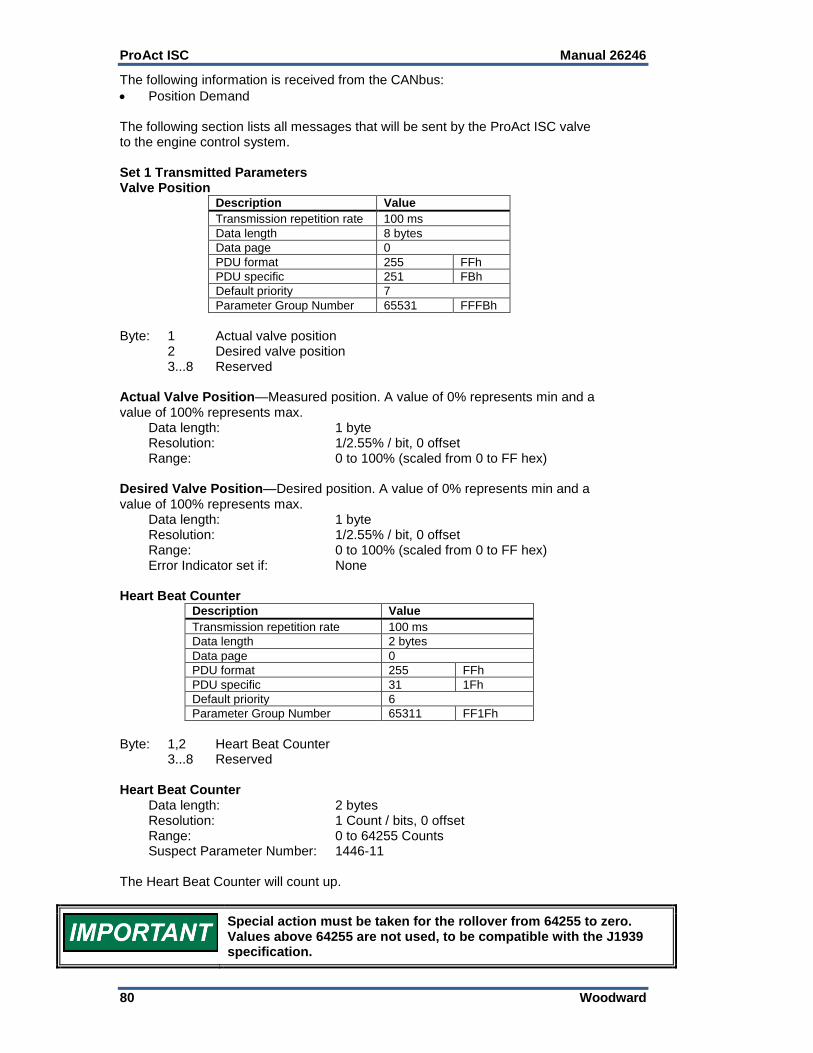
ProAct ISC Manual 26246
80 Woodward
The following information is received from the CANbus:
Position Demand The following section lists all messages that will be sent by the ProAct ISC valve to the engine control system. Set 1 Transmitted Parameters Valve Position
Description Value
Transmission repetition rate 100 ms
Data length 8 bytes
Data page 0
PDU format 255 FFh
PDU specific 251 FBh
Default priority 7
Parameter Group Number 65531 FFFBh
Byte: 1 Actual valve position 2 Desired valve position 3...8 Reserved Actual Valve Position—Measured position. A value of 0% represents min and a value of 100% represents max. Data length: 1 byte Resolution: 1/2.55% / bit, 0 offset Range: 0 to 100% (scaled from 0 to FF hex) Desired Valve Position—Desired position. A value of 0% represents min and a value of 100% represents max. Data length: 1 byte Resolution: 1/2.55% / bit, 0 offset Range: 0 to 100% (scaled from 0 to FF hex) Error Indicator set if: None Heart Beat Counter
Description Value
Transmission repetition rate 100 ms
Data length 2 bytes
Data page 0
PDU format 255 FFh
PDU specific 31 1Fh
Default priority 6
Parameter Group Number 65311 FF1Fh
Byte: 1,2 Heart Beat Counter 3...8 Reserved Heart Beat Counter Data length: 2 bytes Resolution: 1 Count / bits, 0 offset Range: 0 to 64255 Counts Suspect Parameter Number: 1446-11 The Heart Beat Counter will count up.
Special action must be taken for the rollover from 64255 to zero. Values above 64255 are not used, to be compatible with the J1939 specification.

Manual 26246 ProAct ISC
Woodward 81
Software Version Number If the engine control system needs the software version number it will use the request message below. Request Message
Description Value
Transmission repetition rate On request
Data length 3 bytes
Data page 0
PDU format 234 EAh
PDU specific ProAct address
Default priority 6
Parameter Group Number x EAxxh
Byte: 1 DAh Byte: 2 FEh Byte: 3 0h Response Message
Description Value
Transmission repetition rate On request
Data length 8 bytes
Data page 0
PDU format 254 FEh
PDU specific 218 DAh
Default priority 6
Parameter Group Number 65242 FEDAh
Byte: 1 Number of software identification fields Byte: 2...8 Software version or identifier. Data must be delimited with ASCII
“*”. Pad data with FFh if less than 7 characters. Identification field Data length: 1 byte Range: 1 Software version number Data length: 7 bytes (max of 6 bytes of data plus "*") Range: ASCII characters, delimited by "*" Resolution: 1 character/byte Suspect Parameter Number: 234 Version Number Example: “1.01*” The ASCII data must be displayed without formatting.
Diagnostics from ProAct ISC The information communicated is limited to the current status of the diagnostics and events that the ProAct ISC can perform within its scope. The status is bit mapped to indicate the active or in-active state (see Bit Code Legend section). Two bits are used for every fault condition to indicate the status. A proprietary PGN will be used to communicate the faults.

ProAct ISC Manual 26246
82 Woodward
Diagnostics/Events Request Message
Description Value
Transmission repetition rate On request
Data length 3 bytes
Data page 0
PDU format 234 EAh
PDU specific ProAct address
Default priority 6
Parameter Group Number x EAxxh
Byte: 1 10h Byte: 2 FFh Byte: 3 0h The ProAct ISC will send the following Diagnostics and Events in a sequence.
Description Value
Transmission repetition rate 1 s*
Data length 8 bytes
Data page 0
PDU format 255 FFh
PDU specific 16 10h
Default priority 6
Parameter Group Number 65296 FF10h
* See Transmission Rate for details. Diagnostic information must also be available by request from the En. Byte: 1…4 Diagnostics 5...8 Events Bit Code Legend The ProAct ISC actuator will send the following diagnostics and events status in a sequence.
Bit code Description
00 Inactive
01 Active
10 Reserved
11 Not Available
Bit position in a byte is “7 6 5 4 3 2 1 0” Bit position 0 is least significant bit. Example: Bit position 1 is “1” and all others bits are “0”; byte value is 2.
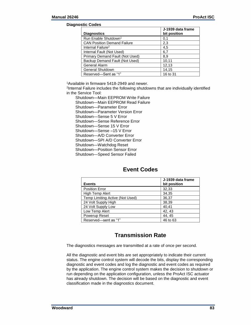
Manual 26246 ProAct ISC
Woodward 83
Diagnostic Codes Diagnostics
J-1939 data frame bit position
Run Enable Shutdown1 0,1
CAN Position Demand Failure 2,3
Internal Failure2 4,5
Internal Fault (Not Used) 6,7
Primary Demand Fault (Not Used) 8,9
Backup Demand Fault (Not Used) 10,11
General Alarm 12,13
General Shutdown 14,15
Reserved—Sent as “1” 16 to 31
1Available in firmware 5418-2949 and newer. 2Internal Failure includes the following shutdowns that are individually identified in the Service Tool: Shutdown—Main EEPROM Write Failure Shutdown—Main EEPROM Read Failure Shutdown—Parameter Error Shutdown—Parameter Version Error Shutdown—Sense 5 V Error Shutdown—Sense Reference Error Shutdown—Sense 15 V Error Shutdown—Sense –15 V Error Shutdown—A/D Converter Error Shutdown—SPI A/D Converter Error Shutdown—Watchdog Reset Shutdown—Position Sensor Error Shutdown—Speed Sensor Failed
Event Codes
Events
J-1939 data frame bit position
Position Error 32,33
High Temp Alert 34,35
Temp Limiting Active (Not Used) 36,37
24 Volt Supply High 38,39
24 Volt Supply Low 40,41
Low Temp Alert 42, 43
Powerup Reset 44, 45
Reserved—sent as “1” 46 to 63
Transmission Rate The diagnostics messages are transmitted at a rate of once per second. All the diagnostic and event bits are set appropriately to indicate their current status. The engine control system will decode the bits, display the corresponding diagnostic and event codes and log the diagnostic and event codes as required by the application. The engine control system makes the decision to shutdown or run depending on the application configuration, unless the ProAct ISC actuator has already shutdown. The decision will be based on the diagnostic and event classification made in the diagnostics document.

ProAct ISC Manual 26246
84 Woodward
Set 1 Incoming CAN Commands This section lists all messages that will be sent by the engine control system to the ProAct ISC actuator. The PGN for commanded position must be different for each ProAct ISC and is determined by the ProAct ISC CAN address harness. Commanded Actuator Position (Demand to ProAct ISC addresses 1–4)
Description
ProAct ISC address 1 Value
ProAct ISC address 2 Value
ProAct ISC address 3 Value
ProAct ISC address 4 Value
Transmission repetition rate
> 5 ms > 5 ms > 5 ms > 5 ms
Data length 8 bytes 8 bytes 8 bytes 8 bytes
Data page 0 0 0 0
PDU format 255 FFh 255 FFh 255 FFh 255 FFh
PDU specific 22 16h 23 17h 24 18h 25 19h
Default priority 1 1 1 1
Parameter Group Number
65302 FF16h 65303 FF17h 65304 FF18h 65305 FF19h
Byte: 1...4 Actuator Position Demand 5...8 Reserved Valve Position Demand Data length: 4 bytes Resolution: 2.56E-8 %/bit, 5% offset Range: –5 to 105 % (scaled from 0 to FFFFFFFF
hex) Suspect Parameter Number: 1442
The resolution and range is a required deviation from the SAE specification to meet application accuracy. Data is transmitted with least significant byte first, per J1939.
Arbitration Typical Arbitration field (information only) using 29 bits: Example using Heart Beat Counter in Extension Set 1
Figure 8-1. Typical Arbitration Field Example

Manual 26246 ProAct ISC
Woodward 85
Chapter 9. Troubleshooting
Introduction
The actions described in this troubleshooting section are not always appropriate in every situation. Always make sure that any action taken will not result in loss of equipment, personal injury, or loss of life.
The engine, turbine, or other type of prime mover should be equipped with an overspeed shutdown device to protect against runaway or damage to the prime mover with possible personal injury, loss of life, or property damage. The overspeed shutdown device must be totally independent of the prime mover control system. An overtemperature or overpressure shutdown device may also be needed for safety, as appropriate.
The ProAct ISC wiring must be in accordance with North American Class I, Division 2 or Zone 2 wiring methods as applicable, and in accordance with the authority having jurisdiction.
The ProAct™ ISC is used on prime movers that typically have a high noise level. Always use appropriate hearing protection while working around the ProAct ISC.
There are two parts to the troubleshooting section:
Troubleshooting the ProAct ISC
Troubleshooting Diagnostic Flags The first section is used for situations where the system is not acting correctly, but the ProAct ISC is not giving any diagnostic flags. The second section is used if the ProAct ISC has diagnostic flags active.
Troubleshooting the ProAct ISC
Problem Description Possible Source Possible Action
The ProAct ISC is not communicating with the service tool.
There is no power supplied to the ProAct ISC. The wiring between the ProAct ISC and the laptop is incorrect. The Service tool is disconnected. The wrong communication port has been selected.
Check fuse, wiring, and battery voltage. Check wiring according to the wiring diagram. Connect the service tool by using the connect menu. If connected, use disconnect and then re-connect with the correct communication port.

ProAct ISC Manual 26246
86 Woodward
Problem Description Possible Source Possible Action
The ProAct ISC is not opening the fuel control valve during engine cranking.
The Run Enable input is not enabled. See overview screen on service tool. The ProAct ISC has detected a shutdown situation and has not been reset. There is no power supplied to the ProAct ISC. The ProAct ISC does not read any speed. MPU defect, wiring defect, or incorrect MPU installation. The ProAct ISC reads an actual engine speed below the start speed threshold. The Start fuel 1 and or 2 setup is incorrectly set to zero position.
Make sure the run enable input is made active. Check wiring. Reset the ProAct ISC by cycling power to the control, hitting reset on the Service Tool, or toggling the run enable switch to off for 2 seconds and then back on again. Check fuse, wiring, and battery voltage. Fix or replace MPU, fix wiring or install MPU correctly according to the MPU manual. Engine is cold and start speed is set too high. Lower start speed threshold. Set up the Start Fuel to the correct value for this engine.
The engine will not go to rated speed.
The Idle Rated input wiring is defective. See overview screen for input position. The high, low, and active open or closed selection for the Idle Rated input is selected incorrectly. The ProAct ISC is not configured for Idle Rated operation.
Check wiring. Set up the correct input modes. Configure the ProAct ISC for Idle Rated operation if that is the correct operation mode.
The engine will not go to idle speed.
The Idle Rated input wiring is defective. See overview screen for input position. The high, low, and active open or closed selection for the Idle Rated input is selected incorrectly. The ProAct ISC is not configured for Idle Rated operation.
Check wiring. Set up the correct input modes. Configure the ProAct ISC for Idle Rated operation if that is the correct operation mode.
The engine will not raise the speed setpoint.
The Raise input wiring is defective. See overview screen for input position. The high, low, and active open or closed selection for the Raise input is selected incorrectly. The ProAct ISC is not configured for Raise Lower operation. The Lower input is also active and the Analog Raise Lower is configured. The lower is active and only Raise Lower is selected. The ProAct ISC will lower the speed if Raise and Lower are selected at the same time.
Check wiring. Set up the correct input modes. Configure the ProAct ISC for Raise Lower operation or Raise Lower and Analog if that is the correct operation mode. Set up the lower input to the correct state. The engine will not lower the speed setpoint. Set up the lower input to the correct state. The engine will not lower the speed setpoint.

Manual 26246 ProAct ISC
Woodward 87
Problem Description Possible Source Possible Action
The engine will not lower the speed setpoint.
The Lower input wiring is defective. See overview screen for input position. The high, low, and active open or closed selection for the Raise input is selected incorrectly. The ProAct ISC is not configured for Raise lower operation. The Raise input is also active and the analog Raise Lower is configured. The control is in analog mode.
Check wiring. Set up the correct input modes. Configure the ProAct ISC for Raise Lower operation or raise lower and analog if that is the correct operation mode. Set the lower input to the correct state. The engine will not lower the speed setpoint.
Troubleshooting Diagnostic Flags
Error Flag Description Possible Source Possible Action
Power Up Reset The power up reset flag is set every time power to the ProAct ISC has been lost and is restored.
Normal power up of the ISC. Loss of power or intermittent power supply wiring. Power supply wiring to long or to thin. ISC will reset during transient power uses.
No action needed. Possibly reset control. Check wiring for bad or loss connection. Make sure wiring is of the correct thickness and length according to manual.
Watchdog Reset If the watchdog has reset the ProAct ISC, this flag will set.
After software update, the software watchdog will reset the ProAct ISC. The software is disrupted by EMI or an internal component failure.
This is a normal situation. Reset the error code and reset the stored errors. This is an abnormal situation. Return the unit to Woodward.
Analog Input High This error flag will be set if the analog input is higher than the configured limit.
Analog input is driven outside of the diagnostic limit. Diagnostic limit is setup incorrectly. Analog wiring is shorted to a power source like the battery plus.
Check signal and fix incorrect signal level. Select correct diagnostic limit in the ProAct ISC. Correct wiring problem.
Analog Input Low This error flag will be set if the analog input is lower than the configured limit.
Analog input is driven outside of the diagnostic limit. Diagnostic limit is set up incorrectly. Analog wiring is shorted to a low signal like battery min. Analog signal wiring is lost. The control that is driving the analog input is turned off or damaged.
Check signal and fix incorrect signal level. Select correct diagnostic limit in the ProAct ISC. Correct wiring problem. Correct wiring. Turn on control or check external controls manual for troubleshooting.
Supply Voltage High
The power supply voltage is higher than the diagnostic limits.
Bad or damaged battery. Defective battery charging system. Incorrect setting of power supply voltage level.
Replace battery. Fix battery charging system. Set correct voltage levels on power supply.

ProAct ISC Manual 26246
88 Woodward
Error Flag Description Possible Source Possible Action
Supply Voltage Low
The Power supply voltage is lower than the diagnostic limits.
Defective battery charging system. Power supply wiring to long or to thin. ISC will flag low voltage during higher power uses. Incorrect setting of power supply voltage levels.
Fix battery charging system. Make sure wiring is of the correct thickness and length according to manual. Set correct voltage levels on power supply.
Electrical Temperature High
This error is set if the temperature inside the control is higher than allowed by the specifications.
ProAct ISC has been placed in an environment that is too hot. The internal temperature sensor is defective. This can be determined by checking the temperature of the unit and comparing this to the service tool value of the electronics temperature.
Lower temperature by adding cooling, heat shielding, moving the unit, etc. Return unit to Woodward for repair.
Electrical Temperature Low
ProAct ISC has been place in an environment that is too cold. The internal temperature sensor is defective. This can be determined by checking the temperature of the unit and comparing this to the service tool value of the electronics temperature.
Increase temperature by adding heat. Return unit to Woodward for repair.
Governor High Speed
This error is set if the actual speed if higher than the speed setpoint plus a configured limit for longer than the configured time.
The actuator is not capable of closing the fuel control valve (max torque). The fuel control valve is jammed or stuck. The actuator is setup incorrectly. Zero percent position will not completely close the fuel valve. The linkage is moved or disconnected. The engine is not responding correctly. The detection margins are set too low. The detection time is set up too short. A normal load transient will trigger this error.
Check the torque needed to close the fuel valve against the available torque. Fix or replace valve. Run the position setup wizard to set up the actuator correctly. 0% will close fuel valve. Fix or replace linkage. Check with the engine troubleshooting manual. Set the margins to an acceptable level. Set the detection time to an acceptable level.

Manual 26246 ProAct ISC
Woodward 89
Error Flag Description Possible Source Possible Action
Governor Low Speed
This error is set if the actual speed if lower than the speed setpoint minus a configured limit for longer than the configured time.
The actuator is not capable of opening the fuel control valve (max torque). The fuel control valve is jammed or stuck. The actuator is set up incorrectly. 100% position will not completely open the fuel valve. The linkage is moved or disconnected. The engine is not responding correctly. The fuel supply to the engine is restricted. The load on the engine is too high. The detection margins are set too low. The detection time is set up too short. A normal load transient will trigger this error.
Check the torque needed to open the fuel valve against the available torque. Fix or replace valve. Run the position setup wizard to set up the actuator correctly. 100% will open fuel valve. Fix or replace linkage. Review the engine troubleshooting manual. Open restriction in fuel supply, check filters. Reduce load on the engine to an acceptable limit for this engine. Set the margins to an acceptable level. Set the detection time to an acceptable level.
Max Starting Time The max staring time error is set if the engine is not above run speed within a configured amount of time.
Start fuel is set too low. Engine will not reach run speed. Low temperature of engine will not start engine at start fuel selected. Engine is defective and will not start.
Set start fuel limit to a level where the engine will reach run speed or lower run speed if a possible. Select two start fuels with ramp to ramp to more or less fuel during the engine start. Check with the engine troubleshooting manual.

ProAct ISC Manual 26246
90 Woodward
Error Flag Description Possible Source Possible Action
Overspeed This diagnostic flag is set if the actual engine speed is higher than the overspeed threshold.
The overspeed parameter has not been set. Factory default is zero rpm. Engine dynamics are set up too slow for a sudden load reject. The actuator is not capable of closing the fuel control valve (max torque). The fuel control valve is jammed or stuck. The actuator is set up incorrectly. Zero percent position will not completely close the fuel valve. The linkage is moved or disconnected. The engine is not responding correctly.
Set the correct overspeed value. Increase the gains, decrease gain window, or increase gain ratio. Check the torque needed to close the fuel valve against the available torque. Fix or replace valve. Run the position setup wizard to set up the actuator correctly. 0% will close fuel valve. Fix or replace linkage. Check with the engine troubleshooting manual.
Speed Sensor Failed
This diagnostic flag is set if the MPU input pulses have not been detected or the time between pulses has changed by a factor of 4, and the engine speed was above the start speed threshold.
Damaged, loss of MPU or wiring. Damaged or loss connector. Incorrect installation of MPU sensor. Missing pulses on MPU teeth wheel.
Fix wiring or replace. Fix connector or replace. Correct MPU installation. See MPU installation manual. Make sure MPU teeth wheel is not missing any teeth’s.
Position Error If the demanded position and the actual position are outside the configured limits.
Incorrect inertia or friction settings. Binding or excessive friction in the actuator linkage, or stops are set inside the desired range of travel.
Check position dynamics using the Service Tool. Click on Tools, then click on Position Calibration, and perform either the manual or automatic position calibration. Check all mechanical linkages and stops.
Position Sensor Error
If the internal position sensor is outside the diagnostic limits.
Internal failure of position sensor. Return unit to Woodward.
Internal Shutdown All internal shutdowns will set this flag.
The ProAct ISC is defective. Return unit to Woodward.
Main EE PROM Write Failure
The software can’t write to the EEPROM.
The ProAct ISC is defective. Return unit to Woodward.
Main EE PROM Read Failure
The software can’t read from the EEPROM.
The ProAct ISC is defective. Return unit to Woodward.
Parameter Error The software has detected a checksum error on one of the parameter blocks.
You have upgraded the ProAct ISC software with an incompatible parameters set. The ProAct ISC is defective.
Use the software upgrade procedure to fix this problem. Return unit to Woodward.
Parameter Version Error
The version of the parameter set is incorrect.
The ProAct ISC is defective. Return unit to Woodward.
Sense 5 V Error The 5 V power supply is defective.
The ProAct ISC is defective. Return unit to Woodward.

Manual 26246 ProAct ISC
Woodward 91
Error Flag Description Possible Source Possible Action
Sense Reference Error
The ADC reference voltage is defective.
The ProAct ISC is defective. Return unit to Woodward.
Sense 15 V Error The 15 V power supply is defective.
The ProAct ISC is defective. Return unit to Woodward.
Sense –15 V Error
The –15 V power supply is defective.
The ProAct ISC is defective. Return unit to Woodward.
ADC Error The 10 bit ADC converter is defective.
The ProAct ISC is defective. Return unit to Woodward.
SPI ADC Error The 12 bit ADC converter is defective.
The ProAct ISC is defective. Return unit to Woodward.
CAN Bus Off This error is set if the CAN Bus is not On.
Incorrect or intermittent wiring problem. Incorrect or missing termination resistors. Electrical problems within the controller or unit.
Check wiring for broken or loose connection. Verify proper termination resistors at the ends of the CAN network. Possible problem with the ProAct ISC, although additional testing recommended before returning to Woodward.
CAN Bus Demand Too Slow
This error is set if the CAN Bus is communicating slower than the configured messages per second (msg.sec) rate
Incorrect or intermittent wiring problem. Incorrect configuration. Device not sending updates fast enough or regularly (bursts).
Check wiring for bad or lost connection. Verify configuration. Verify ECM messages and update rates. Verify configuration of ProAct ISC min update rate.
CAN Demand No Signal
This error is set if the CAN Bus demand input signal is lost.
CAN demand is missing (no signal). Incorrect ProAct ISC Number. ECM is not sending Demand messages, or is not sending to the correct ProAct ISC number. CAN termination problem. CAN wiring problem. CAN noise problem. CANbus incompatibility with ECM, e.g., baud rate. CAN traffic overload.
Verify CANbus communication and connections. Check the CAN ID inputs to the valve. Verify that the ECM is powered up and sending valid demand messages, and that the correct ProAct ISC ID numbers are selected. Check if the CANbus has the right termination resistor connected at both ends of the bus. Check the CAN wiring for shorts, open connections, interchanged connections, and intermittent contacts. Verify that the CAN wiring is installed according to the installation instruction Verify ECM CANbus compatibility. Verify that there is not excessive CAN traffic that has higher priority than the ProAct ISC demand message.

ProAct ISC Manual 26246
92 Woodward
Chapter 10. Product Support and Service Options
Product Support Options
If you are experiencing problems with the installation, or unsatisfactory performance of a Woodward product, the following options are available: 1. Consult the troubleshooting guide in the manual. 2. Contact the OE Manufacturer or Packager of your system. 3. Contact the Woodward Business Partner serving your area. 4. Contact Woodward technical assistance via email
([email protected]) with detailed information on the product, application, and symptoms. Your email will be forwarded to an appropriate expert on the product and application to respond by telephone or return email.
5. If the issue cannot be resolved, you can select a further course of action to pursue based on the available services listed in this chapter.
OEM or Packager Support: Many Woodward controls and control devices are installed into the equipment system and programmed by an Original Equipment Manufacturer (OEM) or Equipment Packager at their factory. In some cases, the programming is password-protected by the OEM or packager, and they are the best source for product service and support. Warranty service for Woodward products shipped with an equipment system should also be handled through the OEM or Packager. Please review your equipment system documentation for details.
Woodward Business Partner Support: Woodward works with and supports a global network of independent business partners whose mission is to serve the users of Woodward controls, as described here:
A Full-Service Distributor has the primary responsibility for sales, service, system integration solutions, technical desk support, and aftermarket marketing of standard Woodward products within a specific geographic area and market segment.
An Authorized Independent Service Facility (AISF) provides authorized service that includes repairs, repair parts, and warranty service on Woodward's behalf. Service (not new unit sales) is an AISF's primary mission.
A Recognized Engine Retrofitter (RER) is an independent company that does retrofits and upgrades on reciprocating gas engines and dual-fuel conversions, and can provide the full line of Woodward systems and components for the retrofits and overhauls, emission compliance upgrades, long term service contracts, emergency repairs, etc.
A current list of Woodward Business Partners is available at www.woodward.com/directory.
Product Service Options
Depending on the type of product, the following options for servicing Woodward products may be available through your local Full-Service Distributor or the OEM or Packager of the equipment system.
Replacement/Exchange (24-hour service)
Flat Rate Repair
Flat Rate Remanufacture

Manual 26246 ProAct ISC
Woodward 93
Replacement/Exchange: Replacement/Exchange is a premium program designed for the user who is in need of immediate service. It allows you to request and receive a like-new replacement unit in minimum time (usually within 24 hours of the request), providing a suitable unit is available at the time of the request, thereby minimizing costly downtime.
This option allows you to call your Full-Service Distributor in the event of an unexpected outage, or in advance of a scheduled outage, to request a replacement control unit. If the unit is available at the time of the call, it can usually be shipped out within 24 hours. You replace your field control unit with the like-new replacement and return the field unit to the Full-Service Distributor.
Flat Rate Repair: Flat Rate Repair is available for many of the standard mechanical products and some of the electronic products in the field. This program offers you repair service for your products with the advantage of knowing in advance what the cost will be.
Flat Rate Remanufacture: Flat Rate Remanufacture is very similar to the Flat Rate Repair option, with the exception that the unit will be returned to you in “like-new” condition. This option is applicable to mechanical products only.
Returning Equipment for Repair
If a control (or any part of an electronic control) is to be returned for repair, please contact your Full-Service Distributor in advance to obtain Return Authorization and shipping instructions.
When shipping the item(s), attach a tag with the following information:
return number;
name and location where the control is installed;
name and phone number of contact person;
complete Woodward part number(s) and serial number(s);
description of the problem;
instructions describing the desired type of repair.
Packing a Control
Use the following materials when returning a complete control:
protective caps on any connectors;
antistatic protective bags on all electronic modules;
packing materials that will not damage the surface of the unit;
at least 100 mm (4 inches) of tightly packed, industry-approved packing material;
a packing carton with double walls;
a strong tape around the outside of the carton for increased strength.
To prevent damage to electronic components caused by improper handling, read and observe the precautions in Woodward manual 82715, Guide for Handling and Protection of Electronic Controls, Printed Circuit Boards, and Modules.
Replacement Parts
When ordering replacement parts for controls, include the following information:
the part number(s) (XXXX-XXXX) that is on the enclosure nameplate;
the unit serial number, which is also on the nameplate.

ProAct ISC Manual 26246
94 Woodward
Engineering Services
Woodward’s Full-Service Distributors offer various Engineering Services for our products. For these services, you can contact the Distributor by telephone or by email.
Technical Support
Product Training
Field Service
Technical Support is available from your equipment system supplier, your local Full-Service Distributor, or from many of Woodward’s worldwide locations, depending upon the product and application. This service can assist you with technical questions or problem solving during the normal business hours of the Woodward location you contact.
Product Training is available as standard classes at many Distributor locations. Customized classes are also available, which can be tailored to your needs and held at one of our Distributor locations or at your site. This training, conducted by experienced personnel, will assure that you will be able to maintain system reliability and availability.
Field Service engineering on-site support is available, depending on the product and location, from one of our Full-Service Distributors. The field engineers are experienced both on Woodward products as well as on much of the non-Woodward equipment with which our products interface.
For information on these services, please contact one of the Full-Service Distributors listed at www.woodward.com/directory.
Contacting Woodward’s Support Organization
For the name of your nearest Woodward Full-Service Distributor or service facility, please consult our worldwide directory published at www.woodward.com/directory.
You can also contact the Woodward Customer Service Department at one of the following Woodward facilities to obtain the address and phone number of the nearest facility at which you can obtain information and service.
Products Used In Electrical Power Systems
Facility ---------------- Phone Number
Brazil -------------- +55 (19) 3708 4800
China ----------- +86 (512) 6762 6727
Germany:
Kempen ---- +49 (0) 21 52 14 51
Stuttgart -- +49 (711) 78954-510
India --------------- +91 (129) 4097100
Japan -------------- +81 (43) 213-2191
Korea -------------- +82 (51) 636-7080
Poland -------------- +48 12 295 13 00
United States ---- +1 (970) 482-5811
Products Used In Engine Systems
Facility ---------------- Phone Number
Brazil -------------- +55 (19) 3708 4800
China ----------- +86 (512) 6762 6727
Germany ------- +49 (711) 78954-510
India --------------- +91 (129) 4097100
Japan -------------- +81 (43) 213-2191
Korea -------------- +82 (51) 636-7080
The Netherlands - +31 (23) 5661111
United States ---- +1 (970) 482-5811
Products Used In Industrial Turbomachinery
Systems Facility ---------------- Phone Number
Brazil -------------- +55 (19) 3708 4800
China ----------- +86 (512) 6762 6727
India --------------- +91 (129) 4097100
Japan -------------- +81 (43) 213-2191
Korea -------------- +82 (51) 636-7080
The Netherlands - +31 (23) 5661111
Poland -------------- +48 12 295 13 00
United States ---- +1 (970) 482-5811
For the most current product support and contact information, please visit our website directory at www.woodward.com/directory.

Manual 26246 ProAct ISC
Woodward 95
Technical Assistance
If you need to contact technical assistance, you will need to provide the following information. Please write it down here before contacting the Engine OEM, the Packager, a Woodward Business Partner, or the Woodward factory:
General
Your Name
Site Location
Phone Number
Fax Number
Prime Mover Information
Manufacturer
Engine Model Number
Number of Cylinders
Type of Fuel (gas, gaseous, diesel, dual-fuel, etc.)
Power Output Rating
Application (power generation, marine, etc.)
Control/Governor Information
Control/Governor #1
Woodward Part Number & Rev. Letter
Control Description or Governor Type
Serial Number
Control/Governor #2
Woodward Part Number & Rev. Letter
Control Description or Governor Type
Serial Number
Control/Governor #3
Woodward Part Number & Rev. Letter
Control Description or Governor Type
Serial Number
Symptoms
Description
If you have an electronic or programmable control, please have the adjustment setting positions or the menu settings written down and with you at the time of the call.
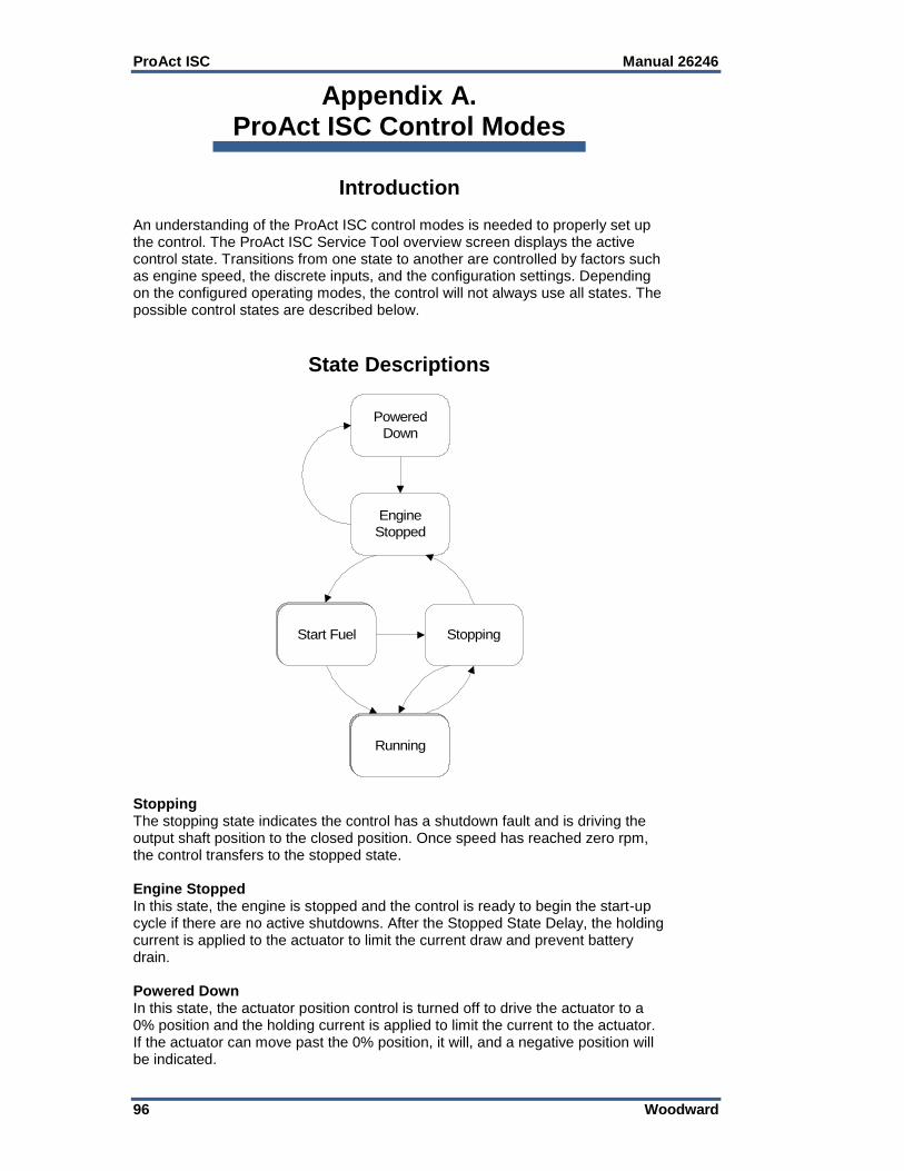
ProAct ISC Manual 26246
96 Woodward
Appendix A. ProAct ISC Control Modes
Introduction An understanding of the ProAct ISC control modes is needed to properly set up the control. The ProAct ISC Service Tool overview screen displays the active control state. Transitions from one state to another are controlled by factors such as engine speed, the discrete inputs, and the configuration settings. Depending on the configured operating modes, the control will not always use all states. The possible control states are described below.
State Descriptions
Powered
Down
Engine
Stopped
Stopping
Running
Start Fuel
Stopping The stopping state indicates the control has a shutdown fault and is driving the output shaft position to the closed position. Once speed has reached zero rpm, the control transfers to the stopped state. Engine Stopped In this state, the engine is stopped and the control is ready to begin the start-up cycle if there are no active shutdowns. After the Stopped State Delay, the holding current is applied to the actuator to limit the current draw and prevent battery drain. Powered Down In this state, the actuator position control is turned off to drive the actuator to a 0% position and the holding current is applied to limit the current to the actuator. If the actuator can move past the 0% position, it will, and a negative position will be indicated.

Manual 26246 ProAct ISC
Woodward 97
Start Fuel 1 The Start Fuel 1 state is selected once the engine speed goes higher than the Start Speed 1 threshold. In this state, the actuator position is set to the Start Fuel 1 value. Start Fuel 2 The Start Fuel 2 state is selected once the engine speed goes higher then the Start Speed 2 threshold. In this state, the actuator position is ramped to the Start Fuel 2 value. This state is only used if two start fuels are selected. Ramping to Idle Indicates the speed setpoint in ramping up to idle speed setpoint during a start sequence. Ramping to idle only happens if configured for Idle / Rated. This state is selected once the engine speed goes higher than the run speed threshold. At the moment this state is entered, the control captures and sets the actual engine speed as the speed setpoint, then ramps to the idle set point at the ramp to idle rate. Running Idle Indicates the speed setpoint is at the configured Idle speed setting. To leave this state, the rated command must be issued. Ramping The ramping state is used to ramp from one set point to another set point. If the setpoint is switched between Idle and Rated or Rated 1 and Rated 2, we will use this state to ramp with the acceleration or deceleration ramp rate. If Raise or Lower are momentarily selected (halt), the ramp will stop and the setpoint will remain at the last position. The setpoint can be adjusted from this point using the Raise/Lower commands. If the halt command is selected when ramping from idle to rated and the setpoint is below the normal adjustment range, the setpoint will continue to ramp and then halt at the minimum setting of the speed adjustment band. Running Rated 1 Indicates the unit is running at the Rated 1 set point or the changed Rated 1 set point if raise, lower, or analog control is used. Running Rated 2 Indicates the unit is running at the Rated 2 set point or the changed Rated 2 set point if raise, lower, or analog control is used.
State Transitions Powered Down State The control changes from this state to the Engine Stopped state when:
The Run Enable switch is active. Engine Stopped State The control changes from this state to the Start Fuel state when all of the following are true:
Engine speed exceeds the Start Speed 1 Threshold
The Run Enable switch is active
The control is not shutdown
The speed setpoint is not zero The control changes from this state to the Powered Down state when both of the following are true:
The Run Enable switch is not active
The Power Down Delay time period has elapsed

ProAct ISC Manual 26246
98 Woodward
Start Fuel State If one start fuel is configured, the Start Fuel state is simply the Start Fuel 1 sub-state described below. If two start fuels are configured, it consists of the Start Fuel 1 and Start Fuel 2 sub-states.
Start Fuel 2
Start Fuel 1
From Engine Stopped
State
To Stopping State
To Stopping State
To Running State
Figure A-1. Start Fuel State When Two Start Fuels are Configured Start Fuel 1 Sub-state In this state the actuator position is set to the Start Fuel 1 position. The control changes from this state to the Stopping state when any of the following are true:
Engine speed is below (Start Speed 1 Threshold – Start Speed Hysteresis)
The Run Enable switch is not active
The control is shut down
The Max Starting Time period has elapsed Also, the control changes from this state to the Running state when both of the following are true:
One start fuel is configured
Engine speed exceeds the Run Speed Threshold Also, the control changes from this state to the Start 2 sub-state when both of the following are true:
Two start fuels are configured
Engine Speed has exceeded the Start Speed 2 Threshold Start Fuel 2 Sub-state In this state, the actuator position is ramped to the Start Fuel 2 value. The control changes from this state to the Stopping state when any of the following are true:
Engine speed is below (Start Speed 1 Threshold – Start Speed Hysteresis)
The Run Enable switch is not active
The control is shut down
The Max Starting Time period has elapsed Also, the control changes from this state to the Running state when: Engine speed exceeds the Run Speed Threshold

Manual 26246 ProAct ISC
Woodward 99
Running State The running state consists of some or all of the sub-states described below. The speed setpoint configuration determines which of the following sub-states are applicable.
Ramping
Running
Rated 1
From Start Fuel or
Stopping State
To Stopping State
Figure A-2. Running State When Configured for Rated Speed Setpoint
Ramping to
Idle
Running Idle
Ramping
Running
Rated 1
To Stopping State
From Start Fuel or
Stopping State
Figure A-3. Running State When Configured for Idle / Rated Speed Setpoint

ProAct ISC Manual 26246
100 Woodward
Running
Rated 2
Ramping
Running
Rated 1
To Stopping State
From Start Fuel or
Stopping State
Figure A-4. Running State When Configured for Runtime Select Rated 1 / 2 Speed Setpoint
Ramping
Running
Rated 1 or 2
From Start Fuel or
Stopping State
To Stopping State
Rated 1 or Rated 2 is
selected at start-up.
Figure A-5. Running State When Configured for Start-up Select Rated 1 / 2 Speed Setpoint
Ramping to Idle Sub-state In this state, the speed setpoint is ramped to the Idle setpoint at the Ramp to Idle Ramp Rate if the Ramp to Idle Ramp Rate is configured to be active. If the Ramp to Idle Ramp Rate is not configured to be active, the speed setpoint is set immediately to the Idle Setpoint. The Ramping to Idle state is only used when the speed setpoint is configured for Idle / Rated.

Manual 26246 ProAct ISC
Woodward 101
The control changes from this state to the Stopping state if any of the following are true:
Engine speed is below the Stop Speed Threshold
The Run Enable switch is not active
The control is shutdown Also, the control changes from this state to the Running Idle sub-state when both of the following are true:
The Idle / Rated switch is set to Idle
The Ramp to Idle Ramp Rate is not configured to be active, or engine speed has reached the Idle Setpoint
Also, the control changes from this state to the Ramping sub-state when: The Idle / Rated switch selects the Rated Setpoint. Running Idle Sub-state In this state the engine is running at the Idle Setpoint speed. The Running Idle state is only used when the speed setpoint is configured for Idle / Rated. The control changes from this state to the Stopping state if any of the following are true:
Engine speed is below the Stop Speed Threshold
The Run Enable switch is not active
The control is shutdown The control changes from this state to the Ramping sub-state when:
The Idle / Rated switch selects the Rated Setpoint Ramping Sub-state In this state the engine speed is ramped from one setpoint to another at the Acceleration Ramp Rate or the Deceleration Ramp Rate, as applicable. If the setpoint selection changes while ramping (for example, changing the Idle / Rated input back to Rated while ramping from Rated to Idle), the ramp will change direction and rate as required to reach the new setpoint value. If, while ramping, the Raise or Lower discrete inputs become active, the control will exit this state, and the speed setpoint will be controlled by the Raise / Lower inputs. The Ramping state is not used if the speed setpoint is configured for Rated. The control changes from this state to the Stopping state if any of the following are true:
Engine speed is below the Stop Speed Threshold
The Run Enable switch is not active
The control is shutdown Also, the control changes from this state to the Running Rated 1, Running Rated 2, or Running Idle states if either of the following is true:
The speed setpoint has reached the selected setpoint (or selected setpoint + modifier range, if applicable)
The Raise or Lower discrete input is active Running Rated 1 Sub-state In this state, the engine is running at the Rated 1 speed setpoint, or the modified setpoint if speed modifiers are configured.

ProAct ISC Manual 26246
102 Woodward
The control changes from this state to the Stopping state if any of the following are true:
Engine speed is below the Stop Speed Threshold
The Run Enable switch is not active
The control is shutdown Also, the control changes from this state to the Ramping state when:
A different setpoint is selected Running Rated 2 Sub-state In this state, the engine is running at the Rated 2 speed setpoint, or the modified setpoint if speed modifiers are configured. The control changes from this state to the Stopping state if any of the following are true:
Engine speed is below the Stop Speed Threshold
The Run Enable switch is not active
The control is shutdown Also, the control changes from this state to the Ramping state when:
A different setpoint is selected Stopping State The control will change to the Engine Stopped state if both of the following are true:
Engine speed is zero
The Stop State Delay period has elapsed The control will change to the Running state if all of the following are true:
The Run Enable switch is active
Engine speed is greater than or equal to the Stop Speed Threshold
The control is not shut down
The Max Starting Time period has not elapsed
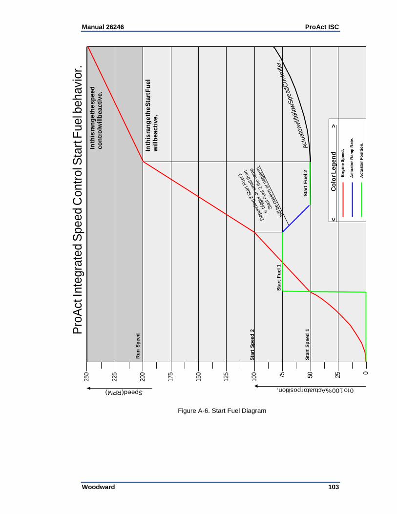
Manual 26246 ProAct ISC
Woodward 103
175
150
125
100 75
50
25 0
200
225
250
Speed (RPM)
Pro
Act I
nte
gra
ted
Sp
ee
d C
on
tro
l Sta
rt F
ue
l be
ha
vio
r.
Ru
n S
peed
Actu
ato
r R
am
p R
ate
.
Actu
ato
r P
osit
ion
.
In th
is ra
ng
e th
e s
pe
ed
co
ntr
ol w
ill b
e a
cti
ve
.
<
Co
lor
Le
ge
nd
>
En
gin
e S
peed
.
Sta
rt S
peed
1
Sta
rt S
peed
2
In th
is ra
ng
e th
e S
tart
Fu
el
wil
l be
ac
tiv
e.
Act
uato
r will
follo
w S
peed
Controlle
r.
0 to 100 % Actuator position.
Sta
rt F
uel 1
Sta
rt F
uel 2
Depend
ing if
Sta
rt F
uel 1
is b
igger
or
small
then
Sta
rt F
uel 2
the r
am
p
will
be p
osi
tive o
r negativ
e.
Figure A-6. Start Fuel Diagram

ProAct ISC Manual 26246
104 Woodward
14
00
12
00
10
00
800
600
400
200 0
16
00
18
00
20
00
Speed (RPM)
Pro
Act I
nte
gra
ted S
peed C
ontr
ol S
peed s
et p
oin
t behavio
r.
Mo
dif
ier
Lo
wer
lim
it
Ru
n S
peed
Sta
rtin
g
Mo
dif
ier
Up
per
lim
it
Rate
d 2
Set
po
int
Rate
d 1
Set
po
int
Idle
Set
Po
int
Idle
Activ
e
Rate
d A
ctiv
e
Rate
d A
ctiv
e
Rai
se, L
ower
and
Ana
log
not a
ctive
Rat
ed 2
Act
ive
No
sp
ee
d s
et
po
int
ch
an
ge
s.
An
alo
g R
am
p r
ate
us
ed
.
Ra
ise
/ L
ow
er
Ra
mp
ra
te
us
ed
.A
cc
el
/ D
ec
el
Ra
mp
ra
te
us
ed
.
Idle
Ra
mp
Ra
te u
se
d.
In th
is ra
ng
e R
ais
e, L
ow
er
an
d A
na
log
wil
l ha
ve
no
eff
ec
t on
the
sp
ee
d s
et p
oin
t.
In th
is ra
ng
e th
e s
pe
ed
co
ntr
ol i
s d
isa
ble
d,
Sta
rt F
ue
l Ac
tiv
e.
In th
is ra
ng
e R
ais
e, L
ow
er
an
d A
na
log
wil
l eff
ec
t th
es
pe
ed
se
t po
int i
f ac
tiv
ate
d.
<
Co
lor
Le
ge
nd
>
Rais
e A
ctiv
e
Rais
e A
ctiv
e
Upper lim
it re
ach
ed
.
Low
er A
ctiv
e
Low
er lim
it re
ach
ed
.
Low
er A
ctiv
e.
Rais
e, L
ow
er a
nd
Ana
log n
ot a
ctiv
e.
Ana
log
activ
e.
Rais
e, Low
er
and A
nalo
g n
ot act
ive.
Idle
, R
ate
d 1
or
Rate
d 2
ha
s ch
anged to
Rate
d 1
.
Rais
e, Low
er,
Analo
g R
ate
d 2
act
ive.
But
Idle
is
als
o A
ctiv
e.
Idle
Act
ive
Figure A-7. Speed Setpoint Diagram
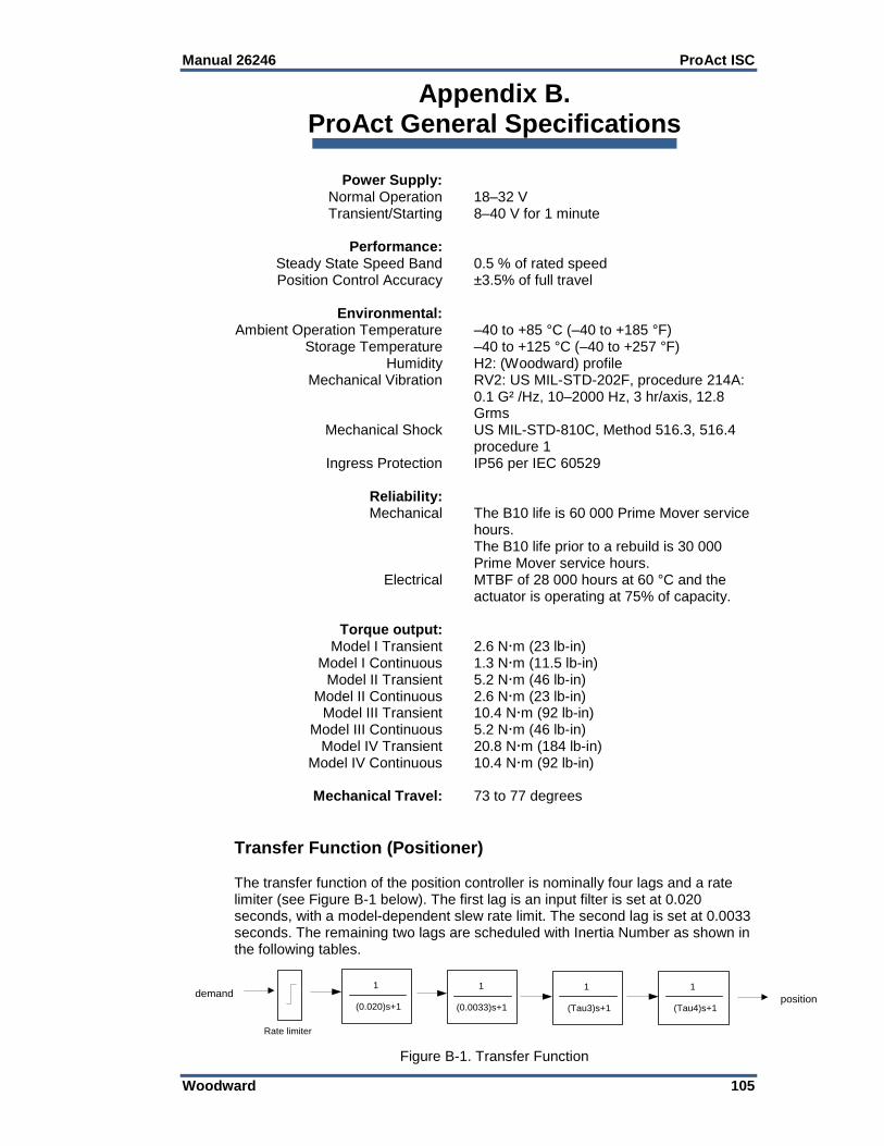
Manual 26246 ProAct ISC
Woodward 105
Appendix B. ProAct General Specifications
Power Supply: Normal Operation 18–32 V Transient/Starting 8–40 V for 1 minute Performance: Steady State Speed Band 0.5 % of rated speed Position Control Accuracy ±3.5% of full travel Environmental: Ambient Operation Temperature –40 to +85 °C (–40 to +185 °F) Storage Temperature –40 to +125 °C (–40 to +257 °F) Humidity H2: (Woodward) profile Mechanical Vibration RV2: US MIL-STD-202F, procedure 214A: 0.1 G² /Hz, 10–2000 Hz, 3 hr/axis, 12.8
Grms Mechanical Shock US MIL-STD-810C, Method 516.3, 516.4
procedure 1 Ingress Protection IP56 per IEC 60529 Reliability: Mechanical The B10 life is 60 000 Prime Mover service
hours. The B10 life prior to a rebuild is 30 000
Prime Mover service hours. Electrical MTBF of 28 000 hours at 60 °C and the
actuator is operating at 75% of capacity. Torque output: Model I Transient 2.6 Nm (23 lb-in) Model I Continuous 1.3 Nm (11.5 lb-in) Model II Transient 5.2 Nm (46 lb-in) Model II Continuous 2.6 Nm (23 lb-in) Model III Transient 10.4 Nm (92 lb-in) Model III Continuous 5.2 Nm (46 lb-in) Model IV Transient 20.8 Nm (184 lb-in) Model IV Continuous 10.4 Nm (92 lb-in) Mechanical Travel: 73 to 77 degrees
Transfer Function (Positioner) The transfer function of the position controller is nominally four lags and a rate limiter (see Figure B-1 below). The first lag is an input filter is set at 0.020 seconds, with a model-dependent slew rate limit. The second lag is set at 0.0033 seconds. The remaining two lags are scheduled with Inertia Number as shown in the following tables.
demand1
(0.020)s+1
1
(0.0033)s+1
1
(Tau3)s+1
1
(Tau4)s+1
Rate limiter
position
Figure B-1. Transfer Function

ProAct ISC Manual 26246
106 Woodward
Size Rate Limiter (deg/s)
Model II 2285
Model III 1882
Model IV, EHT 941
Table B-1 Rate Limiter Values
Tau_3
Tau_4
Model II Inertia
Number
Model III Inertia
Number
Model IV, IV EHT Inertia
Number
0.0040 0.0050 >= 16 >= 17 >= 17
0.0044 0.0063 < 16 < 17 < 17
0.0053 0.0125 < 12 < 13 < 13
0.0063 0.0250 < 7 < 8 < 8
Table B-2 Transfer Function Parameters
Inertia Settings Inertia=Base_Inertia*1.25^InertiaNumber The actuator with no load has inertia = Base_Inertia
Size Base_Inertia
Model II 5.5e-4 Kg-m^2
Model III 6.4e-4 Kg-m^2
Model IV 8.2e-4 Kg-m^2
Model IV EHT 8.2e-4 Kg-m^2
Speed PID Controller The speed control PID is implemented as a standard (interacting) PID. In this form the Kp gain is applied to the Iout, and Dout terms, yielding:
𝑀𝑉(𝑡) = 𝐾𝑝 [𝑒(𝑡) + 1
𝑇𝑖
∫ 𝑒(𝜏)𝑑𝜏 𝑡
0
+ 𝑇𝑑
𝑑
𝑑𝑡𝑒(𝑡)]
where Ti is the integral time Td is the derivative time

Manual 26246 ProAct ISC
Woodward 107
Revision History Changes in Revision U—
Updated Models I and II, III, and IV outline drawings (Figures 1-1, 1-2, and 1-3) Changes in Revision T—
Updated Regulatory Compliance section with new EU directive
New Declaration of Conformity & Declaration of Incorporation Changes in Revision R—
Corrected inertia settings (page 106) Changes in Revision P—
Updated Electrostatic Discharge Awareness section
Updated MPU Input Diagnostics section for new firmware
Expanded General Specifications section (Appendix B) Changes in Revision N—
Updated Regulatory Compliance information
New Declaration of Conformity & Declaration of Incorporation Changes in Revision M—
Updated control wiring diagram (Figure 1-4)
Updated mounting and grounding information (Chapter 2)
Added warning about Gas Engine Stops
Updated wire shielding information
Updated Figure 3-8 for various ProAct models
Updated Position Error explanation
Added new Figure 4-1 (Communication Harness Connections)
Updated Error Delay explanation
ProAct ISC Manual 26246
108 Woodward
Declarations

Manual 26246 ProAct ISC
Woodward 109

We appreciate your comments about the content of our publications.
Send comments to: [email protected]
Please reference publication 26246U.
ËB26246Uµ¸·¸µ¸Î
PO Box 1519, Fort Collins CO 80522-1519, USA 1041 Woodward Way, Fort Collins CO 80524, USA
Phone +1 (970) 482-5811 Fax +1 (970) 498-3058
Email and Website—www.woodward.com
Woodward has company-owned plants, subsidiaries, and branches, as well as authorized distributors and other authorized service and sales facilities throughout the world.
Complete address / phone / fax / email information for all locations is available on our website.


