Page 1
Probability Calculation for Natural frequency of Anisotropic Stator
Core of Large Turbo-Generator
YIXUAN WANG
College of Mechanical and Electrical Engineering, Xi’an Polytechnic University
19 Jinhua South Road ,Xi’an City,P.R.China E-mail:[email protected]
Abstract: - Techniques for vibration reduction and design of stator core require knowledge of its modal
frequencies, which depend on the geometry shapes, dimensions and material properties. The material properties
of stator core are mainly related to its laminated process and assembly as well as the operating temperature of
turbo-generator. It is found that the generally accepted value of material properties is not valid for the stator
core with laminated silicon steel slice and operating at about 110-120 Celsius. This paper simply summarizes
the method of determining elastic constants of stator core material, and then introduces a simple and effective
method for the calculation of the modal frequencies of stator core. The material model of stator core is thought
anisotropic. The elastic modulus, Poisson’s ratio, and mass density are all considered as uncertainty variables,
obeying Gaussain distribution, and changing in the possible range; and then ANSYS workbench 14.5 program
is used to determine the resonant frequencies and corresponding probability of stator core ,and response
surfaces of natural frequencies vs. elastic constants by statistical method (Six Sigma Analysis). The results have
an important guiding role for the laminated structure design, manufacture process, the fixedness and the
vibration isolation design of stator core.
Key-Words: - Large turbo-Generator, Anisotropic Stator Core, Material Properties, Natural Frequency, Six
Sigma Analysis
1 Introduction
1.1 Previous Works Vibration and acoustic noise in the large turbo-
generator is mainly caused by the oval deformation
of the stator lamination stack due to its radial
magnetic attraction to the rotor [5, 6, 9] .There are
several ways of determining stator core resonant
frequencies and mode shapes of the large turbo-
generator: analytical calculations[7,8,10,18],
numerical computation[1,2,11,12] and experimental
measurements[17].
The paper [15] proposes a measurement method
of the Young modulus, shear modulus, mass density
for stator core of switched reluctance motor.
However, the Young modulus value of stainless
steel (E=2.07×10¹¹N/m2) has been widely used by
researchers in small electric machine vibrations area.
The fact is that the stator lamination steel of a
large turbo-generator is different from stainless steel;
in addition, the material properties may change
during core lamination, manufacturing, and vary
with operation temperature of turbo-generator. In
fact, the Young modulus value of stator core varies
with exciting current, temperature and structure
shape. In other words, the elastic constants and mass
density of the stator core is actually uncertain
variables, distributed in an interval, subject to a
statistical distribution law; so the natural frequency
value for the linear system should be subject to the
same distribution. If Finite Element Method (FEM)
is used to model, the elements of mass matrix and
stiffness matrix are random variables, and the
conventional method cannot be used for the
calculation of natural frequency of stator core, but
the method of probability statistics; for stator core of
large turbine generator, the literature in this area are
rare. Because of the complexity of the material
characteristics of stator core, in the calculation of
the natural frequency of the stator core of large
turbine generator, the all researchers consider that
the material constants are unchanged. This paper is
an in-depth research.
In the author’s paper[3, 4],we consider that the
stator core for large turbo-generator is isotropic
body ,so the calculation of mechanical
characteristic needs only the elastic modulus and
Poisson’s ratio, and material properties is
considered as uncertain variables .
In fact, the stator core assembly of large turbo
generator is an anisotropic body. A new nonlinear
anisotropic model for soft magnetic materials is
proposed for determining electro-magnetic
properties of electromagnetic device [13]and
WSEAS TRANSACTIONS on APPLIED and THEORETICAL MECHANICS Yixuan Wang
E-ISSN: 2224-3429 85 Volume 11, 2016
Page 2
mechanical properties for permanent synchronous
motor[14],but these methods are only applicable to a
small motor, and the properties are all constant. For
125MW large hydro-generator, the papers [16, 17]
consider that the stator core is orthotropic body, and
could be simplified as transversely isotropic body,
but mechanical properties are considered as constant.
1.2 The Works of This Paper
On the basis of author’s paper[3,4], this paper
consider that stator core of 1000MW large turbo-
generator is simplified as orthotropic anisotropic
body, and the elastic constants are uncertain
variables, distributed in an interval, subject to a
statistical distribution law(normal distribution); the
natural frequency and vibration mode are calculated
by means of Six sigma analysis method on ANSYS
Workbench 14.5.
Because of considering the change of the material
constants and uncertainty in the process of the actual
operation of generators, so ones can calculate the
each order natural frequency of the stator core and
the corresponding probability.
Compared with previous work, material model
and calculation model in this paper is more complex,
and more close to the operating condition of the
large turbo generator, the result is more
accurate ,reliable and practical. The increase in the
amount of calculation is not much. These results
have an important guiding role
for the laminated structure design and manufacture
process of stator iron core, and the fixedness and the
vibration isolation design of stator core.
2 Structure and Simplified Mechanics
Model of Stator Core
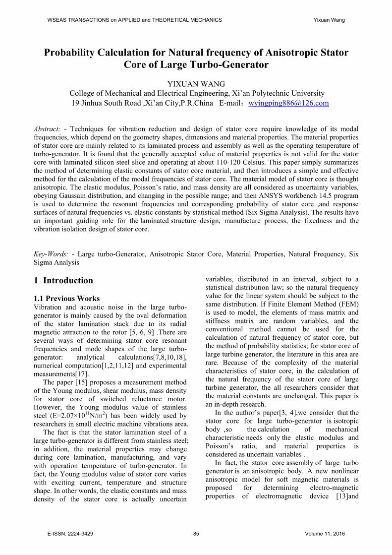
2.1 Structure of Stator Core The inner stator of large turbo-generator consists of
stator winding, stator core, inner stator cage and
locating rib, etc., as shown in Fig.1. As the result of
the laminating and assembly technology of stator
core, the stator iron cores in the turbo generator are
generally laminated with punched fan sheets of
nonlinear soft-magnetic silicon steel, and constituted
by the dislocation seam laminated body(see also
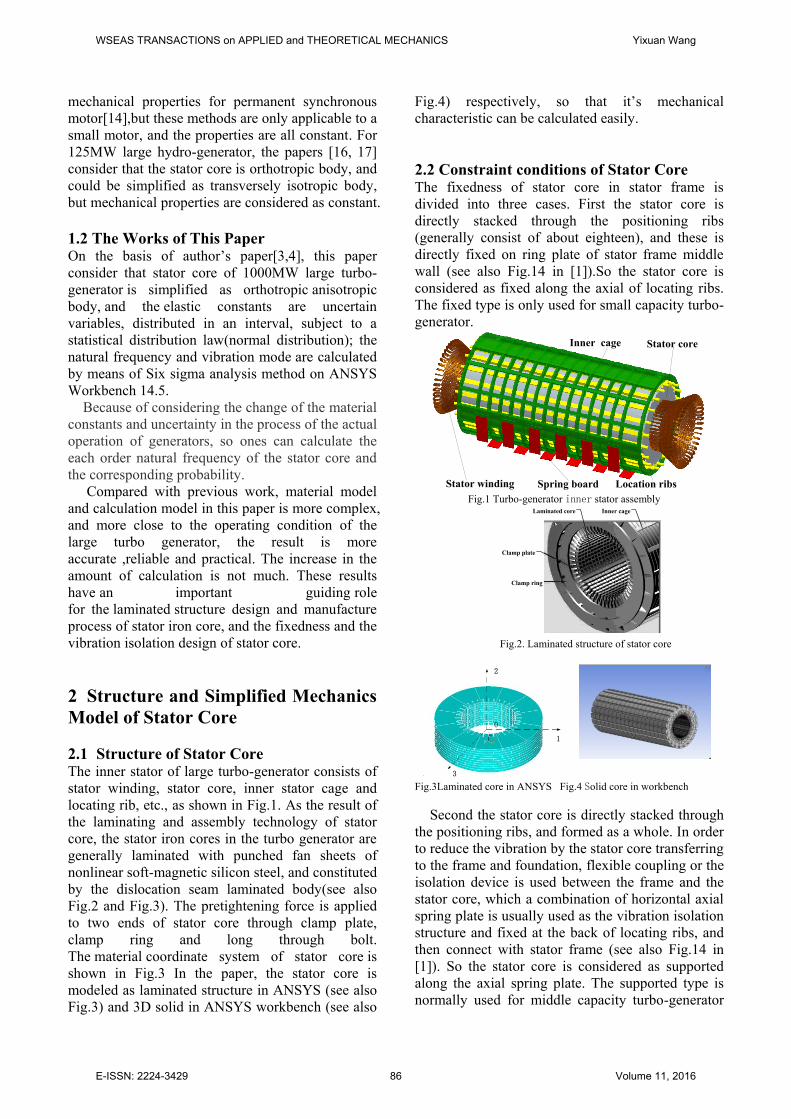
Fig.2 and Fig.3). The pretightening force is applied
to two ends of stator core through clamp plate,
clamp ring and long through bolt.
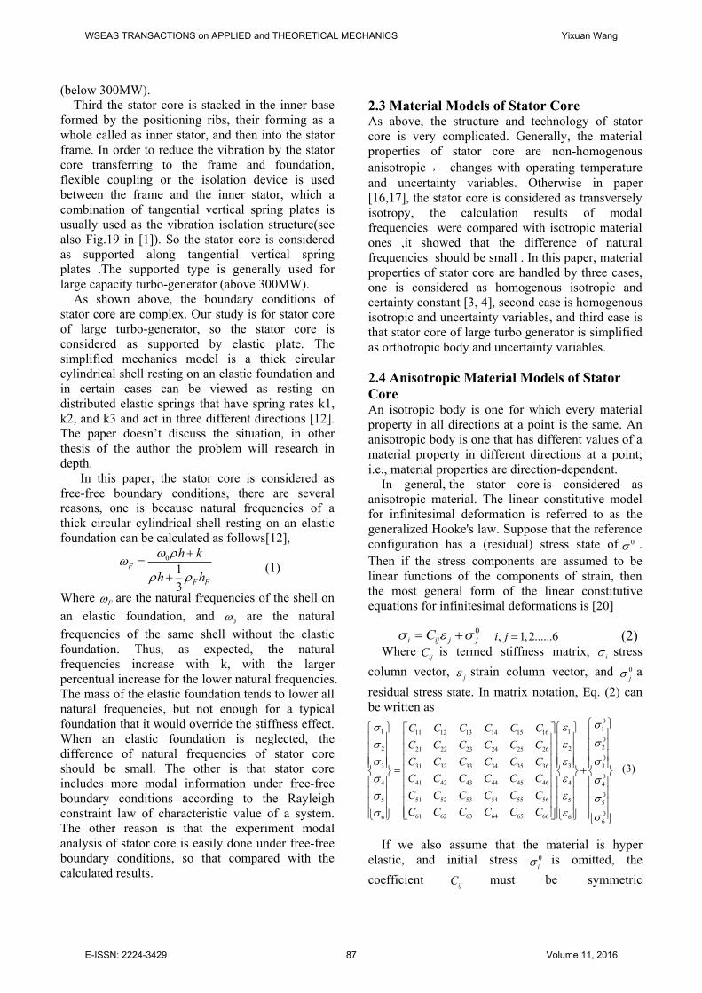
The material coordinate system of stator core is
shown in Fig.3 In the paper, the stator core is
modeled as laminated structure in ANSYS (see also
Fig.3) and 3D solid in ANSYS workbench (see also
Fig.4) respectively, so that it’s mechanical
characteristic can be calculated easily.
2.2 Constraint conditions of Stator Core The fixedness of stator core in stator frame is
divided into three cases. First the stator core is
directly stacked through the positioning ribs
(generally consist of about eighteen), and these is
directly fixed on ring plate of stator frame middle
wall (see also Fig.14 in [1]).So the stator core is
considered as fixed along the axial of locating ribs.
The fixed type is only used for small capacity turbo-
generator.
Inner cage
Spring board Location ribsStator winding
Stator core
Fig.1 Turbo-generator inner stator assembly
Clamp plate
Clamp ring
Inner cageLaminated core
Fig.2. Laminated structure of stator core
0
2
3
1
Fig.3Laminated core in ANSYS Fig.4 Solid core in workbench
Second the stator core is directly stacked through
the positioning ribs, and formed as a whole. In order
to reduce the vibration by the stator core transferring
to the frame and foundation, flexible coupling or the
isolation device is used between the frame and the
stator core, which a combination of horizontal axial
spring plate is usually used as the vibration isolation
structure and fixed at the back of locating ribs, and
then connect with stator frame (see also Fig.14 in
[1]). So the stator core is considered as supported
along the axial spring plate. The supported type is
normally used for middle capacity turbo-generator
WSEAS TRANSACTIONS on APPLIED and THEORETICAL MECHANICS Yixuan Wang
E-ISSN: 2224-3429 86 Volume 11, 2016
Page 3
(below 300MW).
Third the stator core is stacked in the inner base
formed by the positioning ribs, their forming as a
whole called as inner stator, and then into the stator
frame. In order to reduce the vibration by the stator
core transferring to the frame and foundation,
flexible coupling or the isolation device is used
between the frame and the inner stator, which a
combination of tangential vertical spring plates is
usually used as the vibration isolation structure(see
also Fig.19 in [1]). So the stator core is considered
as supported along tangential vertical spring
plates .The supported type is generally used for
large capacity turbo-generator (above 300MW).
As shown above, the boundary conditions of
stator core are complex. Our study is for stator core
of large turbo-generator, so the stator core is
considered as supported by elastic plate. The
simplified mechanics model is a thick circular
cylindrical shell resting on an elastic foundation and
in certain cases can be viewed as resting on
distributed elastic springs that have spring rates k1,
k2, and k3 and act in three different directions [12].
The paper doesn’t discuss the situation, in other
thesis of the author the problem will research in
depth.
In this paper, the stator core is considered as
free-free boundary conditions, there are several
reasons, one is because natural frequencies of a
thick circular cylindrical shell resting on an elastic
foundation can be calculated as follows[12],
(1)
Where F are the natural frequencies of the shell on
an elastic foundation, and 0 are the natural
frequencies of the same shell without the elastic
foundation. Thus, as expected, the natural
frequencies increase with k, with the larger
percentual increase for the lower natural frequencies.
The mass of the elastic foundation tends to lower all
natural frequencies, but not enough for a typical
foundation that it would override the stiffness effect.
When an elastic foundation is neglected, the
difference of natural frequencies of stator core
should be small. The other is that stator core
includes more modal information under free-free
boundary conditions according to the Rayleigh
constraint law of characteristic value of a system.
The other reason is that the experiment modal
analysis of stator core is easily done under free-free
boundary conditions, so that compared with the
calculated results.
2.3 Material Models of Stator Core As above, the structure and technology of stator
core is very complicated. Generally, the material
properties of stator core are non-homogenous
anisotropic , changes with operating temperature
and uncertainty variables. Otherwise in paper
[16,17], the stator core is considered as transversely
isotropy, the calculation results of modal
frequencies were compared with isotropic material
ones ,it showed that the difference of natural
frequencies should be small . In this paper, material
properties of stator core are handled by three cases,
one is considered as homogenous isotropic and
certainty constant [3, 4], second case is homogenous
isotropic and uncertainty variables, and third case is
that stator core of large turbo generator is simplified
as orthotropic body and uncertainty variables.
2.4 Anisotropic Material Models of Stator
Core An isotropic body is one for which every material
property in all directions at a point is the same. An
anisotropic body is one that has different values of a
material property in different directions at a point;
i.e., material properties are direction-dependent.
In general, the stator core is considered as
anisotropic material. The linear constitutive model
for infinitesimal deformation is referred to as the
generalized Hooke's law. Suppose that the reference
configuration has a (residual) stress state of 0 .
Then if the stress components are assumed to be
linear functions of the components of strain, then
the most general form of the linear constitutive
equations for infinitesimal deformations is [20]
0
i ij j jC , 1,2......6i j (2) Where
ijC is termed stiffness matrix, i stress
column vector, j strain column vector, and 0
j a
residual stress state. In matrix notation, Eq. (2) can
be written as
(3)
If we also assume that the material is hyper
elastic, and initial stress 0
i is omitted, the
coefficientijC must be symmetric
0
1
3
F
F F
h k
h h
11 111 12 13 14 15 16
2 221 22 23 24 25 26
3 331 32 33 34 35 36
41 42 43 44 45 464 4
51 52 53 54 55 565 5
61 62 63 64 65 666 6
C C C C C C
C C C C C C
C C C C C C
C C C C C C
C C C C C C
C C C C C C
0
0
2
0
3
0
4
0
5
0
6
WSEAS TRANSACTIONS on APPLIED and THEORETICAL MECHANICS Yixuan Wang
E-ISSN: 2224-3429 87 Volume 11, 2016
Page 4
(ij ijC C ) .Hence, we have 21 independent
stiffness coefficients for the most general elastic
material.
When the elastic coefficients at a point have the
same value for every pair of coordinate systems
which are the mirror images of each other with
respect to a plane, the material is called a
monoclinic material. Thus out of 21 material
parameters, we only have 13 independent
parameters, as indicated below.
(4)
Since the laminated stator core is formed by a
silicon material sheet, having an axis of symmetry
properties, i.e., having three mutually perpendicular
plane of symmetry. When three mutually orthogonal
planes of material symmetry exist, the number of
elastic coefficients is reduced to 9 using arguments
similar to those given for single material symmetry
plane, and such materials are called orthotropic. The
stress-strain relations for an orthotropic material
take the form
(5)
Most simple mechanical property characterization
tests are performed with a known load or stress.
Hence, it is convenient to write the inverse of
relations in (5). The strain-stress relations of an
orthotropic material are given by
(6)
Where
ijS are the compliance coefficients
( 1
C S
)
(7)
where E1, E2, E3 are Young's moduli in 1, 2, and 3
material directions, respectively, ij is Poisson's
ratio, defined as the ratio of transverse strain in the j th direction to the axial strain in the i th direction
when stressed in the ith direction, and G23, G13, G12
are shear moduli in the 2-3, 1-3, and 1-2 planes,
respectively. Since the compliance matrix [S] is the
inverse of the stiffness matrix [C] and the inverse of
a symmetric matrix is symmetric, it follows that the
compliance matrix [S] is also a symmetric matrix.
This in turn implies that the following reciprocal
relations hold
21 12
2 1E E
; 31 13
3 1E E
; 32 23
3 2E E
or, in short
ij ji
i jE E
(no sum on i , j) (8)
For i, j = 1, 2, 3. The 9 independent material
coefficients for an orthotropic material are
E1, E2,E3, G23, G13, G12, 12 , 13 , 23
The stator core assembly is a kind of axis
symmetry material, in the 1-3plane can be
considered isotropic, and obey generalized Hooke's
law. So that
1 3E E (9)
And E1,G13 and 13 meet the following formula
1
13
132(1 )
EG
(10)
So
31 13 (11)
12 32 (12)
21 23 (13)
12 23G G (14)
The 5 independent material coefficients for an
orthotropic stator core material are
E1, E2, 12G , 12 , 13 Sometimes, in order to simplify the analysis, we
think that the stator core is isotropic material. When
11 12 13 16
21 22 23 26
31 32 33 36
44 45
54 55
61 62 63 66
0 0
0 0
0 0
0 0 0 0
0 0 0 0
0 0
C C C C
C C C C
C C C CC
C C
C C
C C C C
1 111 12 13
2 221 22 23
3 331 32 33
444 4
555 5
666 6
0 0 0
0 0 0
0 0 0
0 0 0 0 0
0 0 0 0 0
0 0 0 0 0
C C C
C C C
C C C
C
C
C
1 111 12 13
2 221 22 23
3 331 32 33
444 4
555 5
666 6
0 0 0
0 0 0
0 0 0
0 0 0 0 0
0 0 0 0 0
0 0 0 0 0
S S S
S S S
S S S
S
S
S
3121
1 2 3
3212
1 11 2 3
2 213 23
3 31 2 3
4 4
235 5
6 6
13
12
10 0 0
10 0 0
10 0 0
10 0 0 0 0
10 0 0 0 0
10 0 0 0 0
E E E
E E E
E E E
G
G
G
WSEAS TRANSACTIONS on APPLIED and THEORETICAL MECHANICS Yixuan Wang
E-ISSN: 2224-3429 88 Volume 11, 2016
Page 5
there exist no preferred directions in the material
(i.e., the material has infinite number of planes of
material symmetry), the number of independent
elastic coefficients reduces to 2. Such materials are
called isotropic. For isotropic materials we have
1 2 3
12 13 23
12 23 13
2(1 )
E E E E
G G G G
EG
(15)
Most simple mechanical-property characterization
tests are performed with a known load or stress. The
method for determining the elastic constants of
stator core can also see paper [16, 17].
2.5 Mechanics models of Stator Core In the paper, first stator core is considered as
homogenous isotropic and orthotropic thick circular
cylindrical shell respectively, and is free at two ends;
the material properties of stator core are constant
and isotropic and orthotropic respectively; the FEM
software, ANSYS or ABAQUS, is used to establish
the FEM model of thick shell and 3D solid
separately. Second stator core is considered as
homogenous isotropic and orthotropic thick circular
cylindrical shell respectively, and is free at two ends;
the material properties of stator core are uncertainty
variables, obeying Gaussain distribution; ANSYS
/workbench is used to establish the FEM model of
thick shell, and calculate the cumulative distribution
function (CDF) of the natural frequencies of stator
core, and response surfaces of natural frequencies vs.
elastic constants by statistical method (Six Sigma
Analysis).
3 Idealization Mechanics Model and
Analysis of Stator Core 3.1 Thin Shell Models of Stator Core The stator core is simplified as homogenous
isotropic and orthotropic thin circular cylindrical
shell respectively, and is free at two ends; the
material properties of stator core are constant; a
simplified shell equation is used as theory solution
or exact solution [12]. This simplification has a
large error, the practical were rarely used.
3.2 Thick Shell or 3D Solid Models of Stator
Core The stator core is simplified as homogenous
isotropic and orthotropic thick circular cylindrical
shell respectively, and is free at two ends; the
material properties of stator core are constant; the
energy method, such as Rayleigh-Ritz
method[12,18], is used to calculate natural
frequencies; in this case, the mode shape function
must be assumed by means of experience. The paper
does not in-depth discussion.
3.3 FEM Models of Stator Core On the basis of above analysis, ANSYS and
ABAQUS software are used to build the FEM
models of the stator core of 1000MW turbo-
generator that adopt thick shell element and 3D
solid element respectively, and solve their natural
frequencies and modes.
Specific parameters of the stator core of 1000MW
turbo-generator are as follows: Isotropic material models:
Young's Modulus E=(1.2~1.8)×105 N/mm2
Poisson's Ratio : 0.25-0.35
Density: (0.9~1.1)×7.85×103kg/m3
In the calculation of nature frequency, the elastic
constants values are as follows: 5 2E=1.5 10 N / mm
0.3
6 37.85 10 kg / mm
Orthotropic material models:
5 2
1 3 1.3 1.8 10( /)E E N mm ~
5 2
2 0.5 1.0( 0) 1 /E N mm ~
5 2
12 23 (0.9 1.2) 10 /G G N mm
5 21
13
13
(0.5 0.69) 10 /2(1 )
EG N mm
21 23 0.31~ 0.37
12 32 0.31~ 0.37
31 13 0.3 0.32
In the calculation of nature frequency, the elastic
constants values are as follows:
5 2
1 3 1.69 10 /E E N mm
5 2
2 0.937 10 /E N mm
21 23 0.34
31 13 0.3
5 2
12 23 0.952 10 /G G N mm
WSEAS TRANSACTIONS on APPLIED and THEORETICAL MECHANICS Yixuan Wang
E-ISSN: 2224-3429 89 Volume 11, 2016
Page 6
5 21
13
13
0.65 10 /2(1 )
EG N mm
Number of stator slots is 36; Outer diameter of
stator core 2945 mm; Inner diameter of stator core
1471mm; Yoke inner diameter of stator core
1791mm; Length of stator core 8100 mm; Height of
slot 160 mm;.
Parameters of equivalent cylindrical shell of the
stator core of 1000MW turbo-generator are as
follows: Radius of middle surface is 1184 mm;
Thickness 577 mm; Length of shell 8100 mm;
Material constants are above.
In the dynamics calculation of stator core, the
shell181 and solid185 element are selected,
isotropic and orthotropic material model is adopted
respectively. In the ANSYS/Workbench software,
the certainty dynamics equation is as follows:
(16) Where:
[M],[K] is mass matrix and stiffness matrix
respectively. , u is natural frequency and mode
shape respectively. Obviously, these relate with
geometric dimensions and material parameters. In
our problem, the geometric dimensions are constant,
and material parameters are variation.
The results of natural frequencies are shown in
Table 1, and the mode shapes for isotropic
stator core can also see [1-3]. The results show
that thick shell model and the 3D solid model
can be used as the calculation of the stator core
model. The results of the two models differ
little, comparatively speaking, a thick shell
model is simpler, and fewer elements, nodes
and the number of degrees of freedom, less
computer resources and consumption time
required, faster speed of calculation. This model
is ideal for scanning to optimize the design; and
3D solid model only as a reference. The modal
experiments of stator core prototype is quite
difficult, so far we have not seen the relevant
literature about these of 1000MW generators.
We just use a different model (the number of
nodes and elements) for comparison, and
compare with the calculation results of different
software platforms, so that the accuracy of
calculations is ensured. The FEM solution of
thick shell model have high precision as
comparison with the results [17, 18], and is
available for stator core.
Table 1.Natural Frequencies for Stator Core (Hz)
4 Dynamics statistical model and
calculation of stator core 4.1 Six Sigma Analysis Method [19] In traditional deterministic analyses, uncertainties
are either ignored or accounted for by applying
conservative assumptions. Uncertainties would be
typically ignored if the input parameter has no effect
on the behavior of the component under
investigation. In this case, only the mean values or
some nominal values are used in the analysis.
However, in some situations, the influences of
uncertainties exist, and cannot be neglected, as for
the material properties of stator core, for which the
scatter is not usually ignored.
A Six Sigma Analysis uses statistical distribution
functions (such as the Gaussian or normal
distribution, the uniform distribution, etc.) to
describe uncertain parameters, and allows us to
determine the extent to which uncertainties in the
model affect the results of an analysis.
In a deterministic analysis, computer models are
described with specific numerical and deterministic
values. The accuracy of a deterministic analysis
depends upon the assumptions and input values used
for the analysis.
While scatter and uncertainty naturally occur in
every aspect of dynamics analysis of stator core,
deterministic analyses do not take them into account.
To deal with uncertainties and scatter, use Six
Sigma Analysis, which we can use to answer the
following questions: when the input variables of a
finite element model are subject to scatter, how
large is the scatter of the output parameters? How
robust are the output parameters? When the output
is subject to scatter due to the variation of the input
variables, then what is the probability that a design
criterion given for the output parameters is no
longer met? How large is the probability that an
unexpected and unwanted event takes place (i.e.,
what is the failure probability)? Which input
FEM solution
Freq. Thick shell 3D solid
Oder Isotropic Orthotropic Isotropic Orthotropic
1-6 0 0 0 0
7 142.16 150.91 144.5 155.83
8 142.16 150.92 144.5 155.83
9 168.85 179.41 167.34 182.54
10 201.4 221.88 206.68 229.12
11 201.5 221.88 210.61 233.36
12 204.77 226.47 211.51 235.31
13 204.77 226.47 215.06 248.25
14 230.69 255.62 240.41 264.27
15 263.45 255.62 266.6 270.42
16 263.45 279.98 272.3 280.23
2 0K M u
WSEAS TRANSACTIONS on APPLIED and THEORETICAL MECHANICS Yixuan Wang
E-ISSN: 2224-3429 90 Volume 11, 2016
Page 7
variables contribute the most to the scatter of an
output parameter and to the failure probability?
What are the sensitivities of the output parameter
with respect to the input variables?
Six Sigma Analysis can be used to determine the
effect of one or more variables on the outcome of
the analysis. In addition to the Six Sigma Analysis
techniques available, ANSYS Workbench offers a
set of strategic tools to enhance the efficiency of the
Six Sigma Analysis process.
File DB
ANSYS
Database
File
Model
Database
Probabilistic
Design
Database
File LOOP
Loop File
File PDS
Prob Design
Database
File
Analysis File
(parametrically
defined model)
SAVE RESUME
ANSYS
/CLEAR
PDSAVE PDRESU
PDEXE
/EXIT
(Save Everything)
Fig. 5 Probabilistic design data flow
The Fig.5 shows the flow of information during a
probabilistic design analysis. Note that the analysis
file must exist as a separate entity, and that the
probabilistic design database is not part of the
ANSYS model database.
4.2 The Selection of FEM Model and
Parameters Range As mentioned above, the FEM modeled by thick
shell element has good precision and excellent
computational efficiency. Therefore, in ANSYS
workbench 14.5 program it is used to determine the
resonant frequencies curves of stator core vibration
or response surfaces of natural frequencies vs.
elastic constants .The elastic modulus, Poisson’s
ratio, and mass density are selected as input
variables and changed in the possible range. The
ranges of parameters are shown in Table 2. Natural frequencies are selected as output or
response parameters; in practical computation, any a
frequency concerned with can be selected
for response parameters, here only 10th, 12th and
14th natural frequencies are available. The boundary
conditions of cylindrical shell are free at both ends.
The geometric parameters are the same as above and
fixedness.
4.3 The Design of Experiment 4.3.1 Design parameters
The Input and response parameters are all
uncertainty variables, the distribution type are
all Gaussain( or normal) , the distribution
limit are all from negative infinity to positive
infinity ,the skewness and kurtosis coefficients
are all null, and the others have been given in
Table 2. The stator core model for isotropic has
15 design points, and 150 design points for
orthotropic.
Table 2. Continuous input uncertainty parameter definitions
Table3. Response Parameters Calculated For Isotropic
Table4.Response Parameters Calculated For Orthotropic
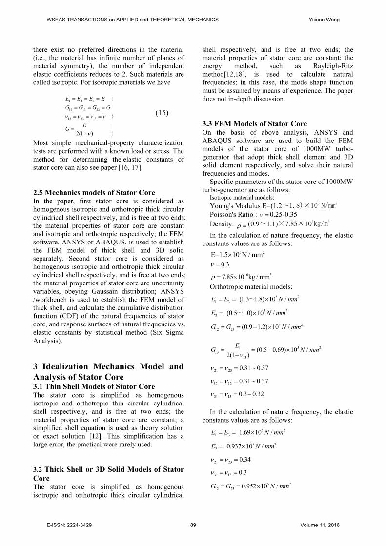
4.3.2 Six sigma analysis input parameter charts
The probability density function (PDF) and
cumulative distribution function (CDF) of Poisson’s
Ratio, Young’s Modulus and density have gained
respectively. Here only these of Young’s Modulus
for isotropic are given in Fig6.
Name Ranges Mean Standard
Deviation 0.25-0.35 0.3 1.5e-002
E (1.268-1.732)e11 1.5e+011 7.5e+009
6637.1-9062.9 7850 392.5
12 0.29-0.39 0.34 0.017
13
0.25-0.35 0.3 0.015
23 0.29-0.39 0.34 0.017
1E (1.43-1.95)e11 1.691e11 8.455e9
2E (2.6-3.7)e11 9.37e10 4.685e9
3E (1.43-1.95)e11 1.691e11 8.455e9
23G (0.878-1.2)e11 1.0385e11 5.19e9
13G (5.5-7.5)e10 6.5e10 3.25e9
12G (0.878-1.2)e11 1.0385e11 5.19e9
Name Minimum Maximum Mean Standard
Deviation 10th Freq. 12th Freq. 14th Freq.
173.77 177.57 200.41
229.64 233.05 262.17
201.14 204.87 230.8
7.4078 7.5368 8.4872
Name Minimum Maximum Mean Standard
Deviation 10th Freq. 12th Freq. 14th Freq.
191.08
197.97
228.3
254.36
257.22
285.25
.222.03 226.66 255.86
7.9485 7.6973 7.996
WSEAS TRANSACTIONS on APPLIED and THEORETICAL MECHANICS Yixuan Wang
E-ISSN: 2224-3429 91 Volume 11, 2016
Page 8
Fig.6 Young's Modulus PDF and CDF for isotropic
4.3.3 Six sigma analysis for isotropic stator core
The size of SSA Sample Set 1 is 10000, and
statistical summary is given in Table3.
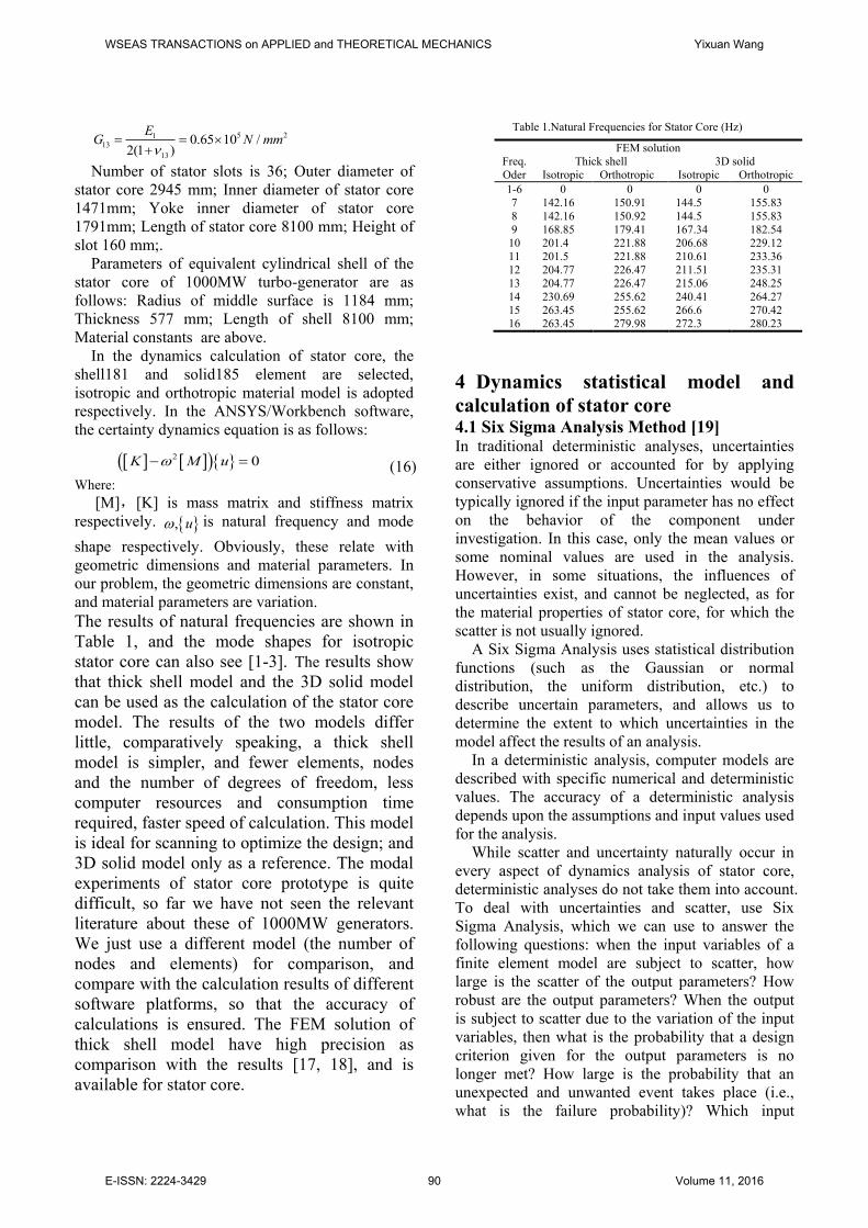
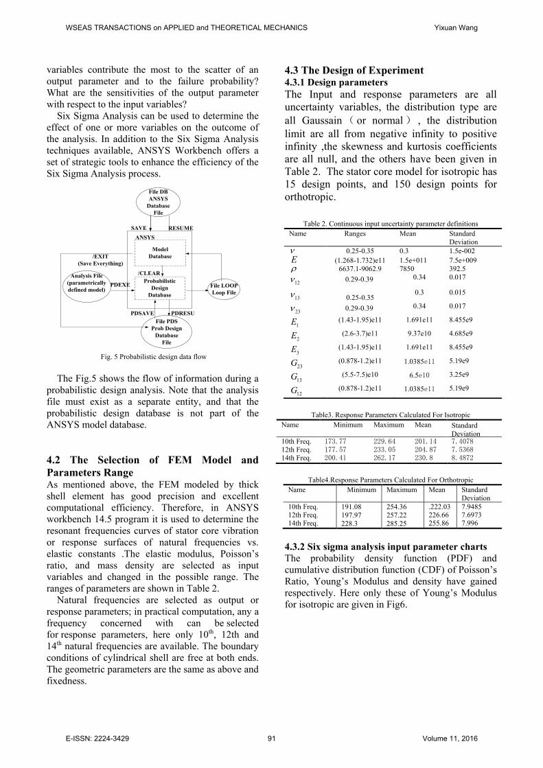
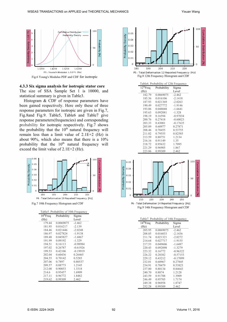
Histogram & CDF of response parameters have
been gained respectively. Here only these of three
response parameters for isotropic are given in Fig.7,
Fig.8and Fig.9. Table5, Table6 and Table7 give
response parameters(frequencies) and corresponding
probability for isotropic respectively. Fig.7 shows
the probability that the 10th natural frequency will
remain less than a limit value of 2.1E+2 (Hz) is
about 90%, which also means that there is a 10%
probability that the 10th natural frequency will
exceed the limit value of 2.1E+2 (Hz).
90
Fig.7 10th Frequency Histogram and CDF
Table5. Probability of 10th Frequency
10thFreq
(Hz)
Probability
Sigma
Level
179.44 0.0069075 -2.462
181.95 0.016217 -2.139
184.46 0.021446 -2.0248
186.97 0.027824 -1.9138
189.48 0.045827 -1.6867
191.99 0.09192 -1.329
194.51 0.16113 -0.98984
197.02 0.26787 -0.61926
199.53 0.42106 -0.19919
202.04 0.60436 0.26465
204.55 0.70142 0.5285
207.06 0.7897 0.80537
209.57 0.88773 1.2145
212.08 0.90853 1.3318
214.6 0.95457 1.6909
217.11 0.96772 1.8482
219.62 0.99309 2.462
Fig.8 12th Frequency Histogram and CDF
Table6. Probability of 12th Frequency
12thFreq
(Hz)
Probability
Sigma
Level
182.79 0.0069075 -2.462
185.36 0.016106 -2.1418
187.93 0.021369 -2.0263
190.49 0.027772 -1.9146
193.06 0.048048 -1.6641
195.63 0.092081 -1.328
198.19 0.16594 -0.97034
200.76 0.27418 -0.60023
203.33 0.43001 -0.17635
205.89 0.60977 0.27871
208.46 0.70455 0.53755
211.02 0.79555 0.82585
213.59 0.88751 1.2134
216.16 0.91149 1.35
218.72 0.95632 1.7095
221.29 0.96905 1.867
223.86 0.99309 2.462
Fig.9 14th Frequency Histogram and CDF
Table7. Probability of 14th Frequency
14thFreq
(Hz)
Probability
Sigma
Level
205.95 0.0069075 -2.462
208.85 0.016033 -2.1436
211.74 0.021321 -2.0272
214.64 0.027717 -1.9155
217.53 0.049606 -1.6487
220.43 0.092098 -1.3279
223.32 0.16772 -0.96322
226.22 0.28382 -0.57153
229.12 0.43212 -0.17099
232.01 0.60967 0.27845
234.91 0.70479 0.53823
237.80 0.80134 0.84643
240.70 0.8874 1.2128
243.59 0.91788 1.3909
246.49 0.95705 1.7174
249.38 0.96958 1.8747
252.28 0.99309 2.462
WSEAS TRANSACTIONS on APPLIED and THEORETICAL MECHANICS Yixuan Wang
E-ISSN: 2224-3429 92 Volume 11, 2016
Page 9
From Table 1, 3, 5, 6 and 7, and Fig.7,Fig.8 and
Fig.9,we know that when the input parameters
are uncertainty and dispersion, natural frequencies
are also dispersed, and the calculation values of
natural frequencies under deterministic input
parameters is approximately equal mean value of
natural frequencies calculated with
the uncertainty input parameters. The distribution
range of the natural frequency is large. When the
probability is more than 0.9, the natural frequencies
has four values.
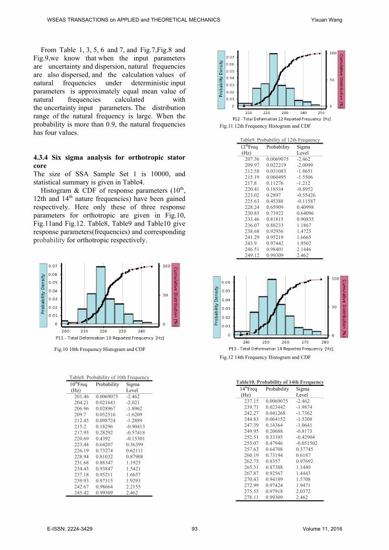
4.3.4 Six sigma analysis for orthotropic stator
core
The size of SSA Sample Set 1 is 10000, and
statistical summary is given in Table4.
Histogram & CDF of response parameters (10th,
12th and 14th nature frequencies) have been gained
respectively. Here only these of three response
parameters for orthotropic are given in Fig.10,
Fig.11and Fig.12. Table8, Table9 and Table10 give
response parameters(frequencies) and corresponding
probability for orthotropic respectively.
Fig.10 10th Frequency Histogram and CDF
Table8. Probability of 10th Frequency
10thFreq
(Hz)
Probability
Sigma
Level
201.46 0.0069075 -2.462
204.21 0.021641 -2.021
206.96 0.028967 -1.8962
209.7 0.052516 -1.6209
212.45 0.098724 -1.2889
215.2 0.18296 -0.90413
217.95 0.28292 -0.57418
220.69 0.4392 -0.15301
223.44 0.64207 0.36399
226.19 0.73274 0.62111
228.94 0.81032 0.87908
231.68 0.88347 1.1925
234.43 0.93847 1.5421
237.18 0.95211 1.6657
239.93 0.97315 1.9293
242.67 0.98664 2.2155
245.42 0.99309 2.462
Fig.11 12th Frequency Histogram and CDF
Table9. Probability of 12th Frequency
12thFreq
(Hz)
Probability
Sigma
Level
207.36 0.0069075 -2.462
209.97 0.022219 -2.0099
212.58 0.031083 -1.8651
215.19 0.060495 -1.5506
217.8 0.11276 -1.212
220.41 0.18534 -0.8952
223.02 0.2897 -0.55426
225.63 0.45388 -0.11587
228.24 0.65909 0.40998
230.85 0.73922 0.64096
233.46 0.81815 0.90835
236.07 0.88233 1.1867
238.68 0.92956 1.4725
241.29 0.95219 1.6665
243.9 0.97442 1.9502
246.51 0.98401 2.1446
249.12 0.99309 2.462
Fig.12 14th Frequency Histogram and CDF
Table10. Probability of 14th Frequency
14thFreq
(Hz)
Probability
Sigma
Level
237.15 0.0069075 -2.462
239.71 0.023442 -1.9874
242.27 0.041268 -1.7362
244.83 0.064152 -1.5208
247.39 0.14364 -1.0641
249.95 0.20688 -0.8173
252.51 0.33395 -0.42904
255.07 0.47946 -0.051502
257.63 0.64708 0.37745
260.19 0.73194 0.6187
262.75 0.8357 0.97692
265.31 0.87388 1.1449
267.87 0.92567 1.4443
270.43 0.94189 1.5708
272.99 0.97424 1.9471
275.55 0.97918 2.0372
278.11 0.99309 2.462
WSEAS TRANSACTIONS on APPLIED and THEORETICAL MECHANICS Yixuan Wang
E-ISSN: 2224-3429 93 Volume 11, 2016
Page 10
From Table 4, 8, 9 and 10, and Fig.10, Fig.11 and
Fig.12, we know that when the input parameters are
uncertainty and dispersion, natural frequencies are
also dispersed. When the uncertainty input
parameters obey the normal distribution
condition, comparing the calculation results of
isotropic and anisotropic stator
core model, we obtain a conclusion: The distribution
range of the natural frequency is larger, and the
calculated values are also larger. When the
probability is more than 0.9, the natural frequencies
has five values. These have an important guiding
role for the laminated structure design and
manufacture process of stator iron core, and the
fixedness and the vibration isolation design of stator
core
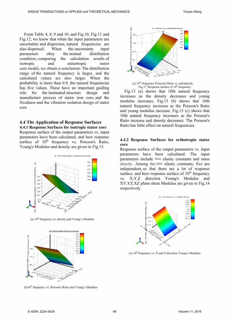
4.4 The Application of Response Surfaces 4.4.1 Response Surfaces for isotropic stator core
Response surface of the output parameters vs. input
parameters have been calculated, and here response
surface of 10th frequency vs. Poisson's Ratio,
Young's Modulus and density are given in Fig.13.
(a) 10th frequency vs. density and Young’s Modulus
(b)10th frequency vs. Poisson's Ratio and Young’s Modulus
(c) 10th frequency Poisson's Ratio vs. and density
Fig.17 Response surface of 10th frequency
Fig.13 (a) shows that 10th natural frequency
increases as the density decreases and young
modulus increases. Fig.13 (b) shows that 10th
natural frequency increases as the Poisson's Ratio
and young modulus increase. Fig.13 (c) shows that
10th natural frequency increases as the Poisson's
Ratio increase and density decreases. The Poisson's
Ratio has little effect on natural frequencies.
4.4.2 Response Surfaces for orthotropic stator core
Response surface of the output parameters vs. input
parameters have been calculated. The input
parameters include nine elastic constants and mass
density. Among the nine elastic constants, five are
independent, so that there are a lot of response
surface, and here response surface of 10th frequency
vs. X,Y,Z direction Young's Modulus and
XY,YZ,XZ plane shear Modulus are given in Fig.14
respectively.
(a) 10th frequency vs. X and Z direction Young’s Modulus
WSEAS TRANSACTIONS on APPLIED and THEORETICAL MECHANICS Yixuan Wang
E-ISSN: 2224-3429 94 Volume 11, 2016
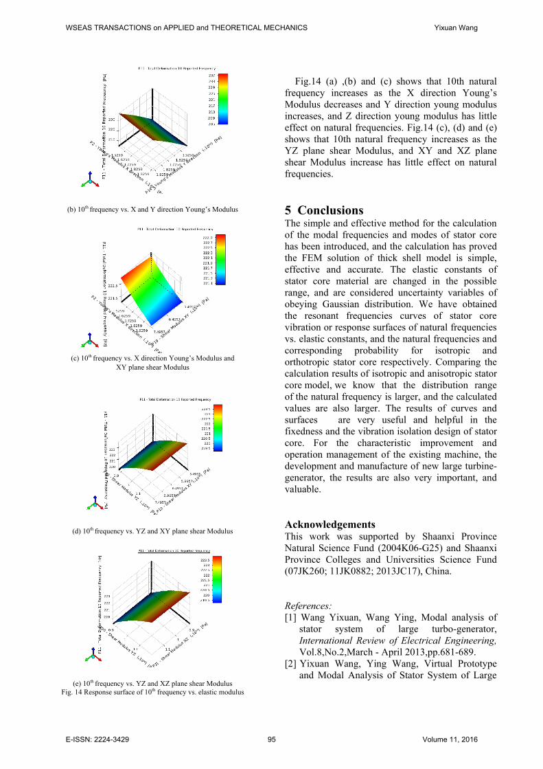
Page 11
(b) 10th frequency vs. X and Y direction Young’s Modulus
(c) 10th frequency vs. X direction Young’s Modulus and
XY plane shear Modulus
(d) 10th frequency vs. YZ and XY plane shear Modulus
(e) 10th frequency vs. YZ and XZ plane shear Modulus
Fig. 14 Response surface of 10th frequency vs. elastic modulus
Fig.14 (a) ,(b) and (c) shows that 10th natural
frequency increases as the X direction Young’s
Modulus decreases and Y direction young modulus
increases, and Z direction young modulus has little
effect on natural frequencies. Fig.14 (c), (d) and (e)
shows that 10th natural frequency increases as the
YZ plane shear Modulus, and XY and XZ plane
shear Modulus increase has little effect on natural
frequencies.
5 Conclusions
The simple and effective method for the calculation
of the modal frequencies and modes of stator core
has been introduced, and the calculation has proved
the FEM solution of thick shell model is simple,
effective and accurate. The elastic constants of
stator core material are changed in the possible
range, and are considered uncertainty variables of
obeying Gaussian distribution. We have obtained
the resonant frequencies curves of stator core
vibration or response surfaces of natural frequencies
vs. elastic constants, and the natural frequencies and
corresponding probability for isotropic and
orthotropic stator core respectively. Comparing the
calculation results of isotropic and anisotropic stator
core model, we know that the distribution range
of the natural frequency is larger, and the calculated
values are also larger. The results of curves and
surfaces are very useful and helpful in the
fixedness and the vibration isolation design of stator
core. For the characteristic improvement and
operation management of the existing machine, the
development and manufacture of new large turbine-
generator, the results are also very important, and
valuable.
Acknowledgements This work was supported by Shaanxi Province
Natural Science Fund (2004K06-G25) and Shaanxi
Province Colleges and Universities Science Fund
(07JK260; 11JK0882; 2013JC17), China.
References:
[1] Wang Yixuan, Wang Ying, Modal analysis of
stator system of large turbo-generator,
International Review of Electrical Engineering,
Vol.8,No.2,March - April 2013,pp.681-689.
[2] Yixuan Wang, Ying Wang, Virtual Prototype
and Modal Analysis of Stator System of Large
WSEAS TRANSACTIONS on APPLIED and THEORETICAL MECHANICS Yixuan Wang
E-ISSN: 2224-3429 95 Volume 11, 2016
Page 12
Turbo-Generator, Applied Mechanics and
Materials, Vols. 190-191 ,2012,pp. 232-236.
[3] Yixuan Wang, Ying Wang, Material Properties
and Natural Frequency of Stator Core of Large
Turbo-Generator, Advanced Materials Research, Vols. 322, 2011, pp. 81-84.
[4] Yixuan Wang, Ying Wang, Research on
Dynamic Characteristics of Stator core of Large
Turbo-Generator, Proceeding of Asia-Pacific
Power and Energy Engineering Conference
(APPEEC 2010) March 28-31, 2010, Chengdu,
china.
[5] Wang Yixuan, Wang Ying, Liu Xin and Qiu
Haifei, Electromagnetic Design and Dynamic
Analysis of Large Turbo-Generator, Journal of
Energy and Power Engineering,. Vol.3,No.12,
2009,pp.19-28.
[6] Wang Yixuan, Wang Ying, etc., Dynamic
Design and Simulation Analysis of 1000MW
Large Turbo Generator, Proceeding of the 2009
IEEE ICMA, changchun, China, 2009 , vol.3,
pp.1650-1655.
[7] WangYixuan, Zhu Jimei., Dynamic optimization
design of stator winding end baskets of large
turbo-generator, Mechanical Science and
Technology for Aerospace Engineering, Vol.27,
No.2, 2008, pp. 205-208.
[8] Wang Yixuan, Zhu Jimei, Research on virtual
prototyping of stator winding end baskets of
large turbo-generator, Proceeding of Symposium
on Global Manufacturing &Simulation
Technology of the 21st Century, Guiyang,
International Academic Publishers, China, 2004,
pp.67-70.
[9] Wang Yixuan, Zhu Jimei, Research on
numerical simulation model of stator winding
end baskets of large turbo-generator, Chinese
Journal of Mechanical Engineering, Vol.41,
No.9 , 2005, pp.217-222.
[10] Wang Yixuan, Dynamical modelling of
stator winding end baskets of large turbo
generator, Journal of Northwest Institute of
Textile Science and Technology, Vol.13, No.4,
1999,pp.339-343.
[11] Marco Amabili, Nonlinear vibrations and
stability of shells and plates, Cambridge
University Press, Cambridge, UK, 2008,
pp.298-308.
[12] Werner Soedel, Vibrations of shells and plates,
Third Edition, Marcel Dekker, Inc. New York,
USA, 2004, pp.184-189.
[13] Hideharu Hiwaki, Hiroshi Murakami etc.,
Reducing iron loss by decreasing stress in
stator core of permanent synchronous motor,
IEEJ Trans. IA, Vol.128,No.7, 2006,pp.852-
856.
[14] D.Lin, P.Zhou, Z.Badics, etc., A New
Nonlinear Anisotropic Model for Soft
Magnetic Materials, CSY0084 of
COMPUMAG ’2005, 2005, pp.1-5.
[15] Zhangjun Tang,, Pragasen Pillay, Avoki M.
Omekanda,Chen Li and Cetin Cetinkaya,
Young’s Modulus for Laminated Machine
Structures With Particular Reference to
Switched Reluctance Motor Vibrations, IEEE
Trans. Ind. Applicat., Vol.40,No.3, 2004,
pp.748–754.
[16] Qiu wengan, Zhang yuncheng, etc., The
computed elastic constant of stator core, Large
Electric Machine Technology,Vol.16,No.1,
1986,pp.41-44.
[17] Luo gongfu, Research on computing
method of anisotropy of stator core of hydro
generator, Eastern Electric Machine, Vol.25,
No.1,1998,pp.47-53.
[18] S.P.Verma, R.K.Singal and K.Willams,
Vibration behaviour of stators of electrical
machines, Part Ⅰ:Theoretical study, Part Ⅱ:
Experimental study, Journal of sound and
vibration, Vol.115, No.1, 1987,pp.1-23.
[19] Six Sigma Analysis Design Xplorer Help
Release 14.5, Documentation for ANSYS
Workbench,2013.
[20] J.N.Reddy, Mechanics of Laminated Plates
and Composite Shells Theory and Analysis
(second edition ), CRC Press LLC, Florida,
USA ,2004,pp.24-28.
WSEAS TRANSACTIONS on APPLIED and THEORETICAL MECHANICS Yixuan Wang
E-ISSN: 2224-3429 96 Volume 11, 2016