14
1994 Ford Probe 2.0L Automatic Automatic Front Air Suspension System ( Anti-Dive / Ground Clearance System ) Revision A October 19, 2006 Jeff Hunt Red Wing, Minnesota [email protected]
| Date post: | 07-Apr-2018 |
| Category: |
Documents |
| Upload: | nikshith-j-mendon |
| View: | 218 times |
| Download: | 0 times |

8/4/2019 Probe Suspension
http://slidepdf.com/reader/full/probe-suspension 1/14
1 9 9 4 F o r d P r o b e
2.0L Automatic
Automatic Front
Air Suspension System
( Anti-Dive / Ground Clearance System )
Revision A
October 19, 2006
Jeff Hunt
Red Wing, Minnesota

8/4/2019 Probe Suspension
http://slidepdf.com/reader/full/probe-suspension 2/14
Page 1
Index
Page Section
1 Index
2 Operation Basics
2 Air Strut Assembly
2 Ride Height Pressure
2 Stage 1 Pressure
2 Stage 2 Pressure
3 Controls
4 Air System
5 Controls System
6 Appendix 1 – Air Bag Installation

8/4/2019 Probe Suspension
http://slidepdf.com/reader/full/probe-suspension 3/14
Page 2
Operation Basics
Air Strut Assembly
The McPherson Strut Spring is replaced with an Air Spring. The height and firmness of the front
struts is then determined by the air pressure applied to the bags.
This system provides 3 pressure levels:
Ride Height Pressure
Ride Height Pressure is set by Regulator 1. This is the default pressure applied to the front struts.
This pressure should be set to allow proper ground clearance and suspension firmness according
to driving style.
Stage 1 Pressure
Stage 1 Pressure is set by Regulator 2. This increased pressure is adjusted to provide a 1 inch lift
above Ride Height pressure. Stage 1 Pressure is applied either by pressing the Stage 1 Button, or
by applying the brake pedal. Once applied the pressure is held for a preset length of time after the
brake or button is released. After the release time, the suspension is returned to Right Height
Pressure.
Stage 2 Pressure
Stage 2 Pressure is set by adjusting the maximum air tank pressure at the compressor pressure
switch. This setting MUST NOT exceed 100 PSI or damage to the front air suspension may
occur. Stage 2 Pressure dumps the maximum air pressure from the tank to the front suspension
when the Stage 2 button is pressed. Pressure is held for a preset length of time after the button is
released, and then returns to Ride Height Pressure.

8/4/2019 Probe Suspension
http://slidepdf.com/reader/full/probe-suspension 4/14
Page 3
Controls
An air pressure gauge is installed in the A-Piller to indicate pressure at the front suspension.
A second pod is provided in the A-Piller with pushbuttons and switches for the Stage 1 and Stage2 air systems. Pressing the momentary buttons will boost the air pressure to the regulator setting.
Once released, the system will hold the boost air pressure for a preset amount of time.
The air system LED Lights will illuminate any time the air solenoid valves are powered (by the
pushbutton, hold timer, or brake pedal).

8/4/2019 Probe Suspension
http://slidepdf.com/reader/full/probe-suspension 5/14
Page 4
Air System
A 12V Compressor provides the compressed air for the suspension system.
The Tank Drain and Water Separator drain should be bled monthly to keep contaminants out of
the air suspension system.
Regulator 1 (Ride Height Pressure) and Regulator 2 (Stage 1 Pressure) should be set with the car
sitting on a level paved surface. Ride Height Pressure should be set so the car sits level and has a
suitable amount of firmness in the suspension for cornering. Stage 1 Pressure should be set so
that it causes approximately a 1 inch lift of the air dam to improve clearance for driveways, and
reduce front end dive during heavy braking.
Main System Air Pressure, used during Stage 2 applications, is adjusted at the compressor
pressure switch. This pressure should be verified at the tank with a known good gauge and mustnot exceed 100 psi.
8/4/2019 Probe Suspension
http://slidepdf.com/reader/full/probe-suspension 6/14
Page 5
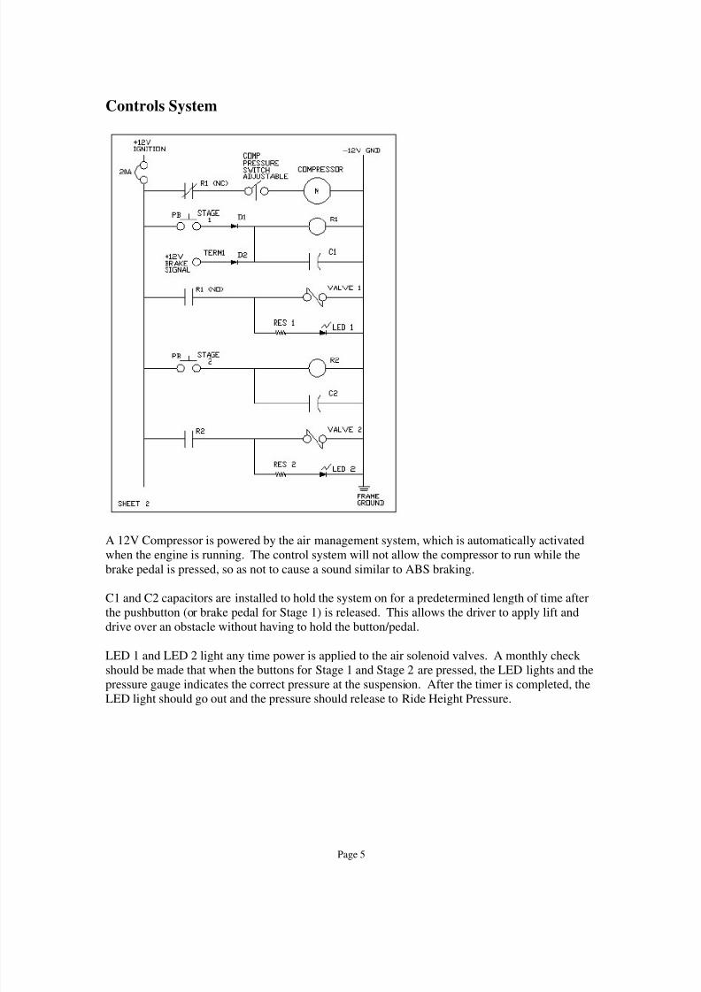
Controls System
A 12V Compressor is powered by the air management system, which is automatically activated
when the engine is running. The control system will not allow the compressor to run while the
brake pedal is pressed, so as not to cause a sound similar to ABS braking.
C1 and C2 capacitors are installed to hold the system on for a predetermined length of time after
the pushbutton (or brake pedal for Stage 1) is released. This allows the driver to apply lift and
drive over an obstacle without having to hold the button/pedal.
LED 1 and LED 2 light any time power is applied to the air solenoid valves. A monthly check
should be made that when the buttons for Stage 1 and Stage 2 are pressed, the LED lights and the
pressure gauge indicates the correct pressure at the suspension. After the timer is completed, the
LED light should go out and the pressure should release to Ride Height Pressure.

8/4/2019 Probe Suspension
http://slidepdf.com/reader/full/probe-suspension 7/14
Page 6
Appendix 1 – Air Bag Installation

8/4/2019 Probe Suspension
http://slidepdf.com/reader/full/probe-suspension 8/14
Universal Air Suspension463 W. Highland AveSan Bernardino, CA 92405800-864-2470WWW.UniversalAirSuspension.com
Universal Air Suspension 800-864-2470

8/4/2019 Probe Suspension
http://slidepdf.com/reader/full/probe-suspension 9/14
Universal Air Suspension463 W. Highland AveSan Bernardino, CA 92405800-864-2470WWW.UniversalAirSuspension.com
Universal Air Suspension 800-864-2470

8/4/2019 Probe Suspension
http://slidepdf.com/reader/full/probe-suspension 10/14
Universal Air Suspension463 W. Highland AveSan Bernardino, CA 92405800-864-2470WWW.UniversalAirSuspension.com
Universal Air Suspension 800-864-2470

8/4/2019 Probe Suspension
http://slidepdf.com/reader/full/probe-suspension 11/14
Universal Air Suspension463 W. Highland AveSan Bernardino, CA 92405800-864-2470WWW.UniversalAirSuspension.com
Universal Air Suspension 800-864-2470

8/4/2019 Probe Suspension
http://slidepdf.com/reader/full/probe-suspension 12/14
Universal Air Suspension463 W. Highland AveSan Bernardino, CA 92405800-864-2470WWW.UniversalAirSuspension.com
Universal Air Suspension 800-864-2470

8/4/2019 Probe Suspension
http://slidepdf.com/reader/full/probe-suspension 13/14
Universal Air Suspension463 W. Highland AveSan Bernardino, CA 92405800-864-2470WWW.UniversalAirSuspension.com
Universal Air Suspension 800-864-2470

8/4/2019 Probe Suspension
http://slidepdf.com/reader/full/probe-suspension 14/14
Universal Air Suspension463 W. Highland AveSan Bernardino, CA 92405800-864-2470WWW.UniversalAirSuspension.com
Using NEW Upper Bearing


