loop: I1 L.D F2, 0(R1) ;load X(i) I2 MUL.D F1, F2, F0 ;multiply a*X(i) I3 L.D F3, 0(R2) ;load Y(i) I4 ADD.D F3, F1, F3 ;add a*X(i)+Y(i) I5 S.D F3, 0(R2) ;store Y(i) I6 DADDUI R1, R1, 8 ;increment X index I7 DADDUI R2, R2, 8 ;increment Y index I8 DSGTUI R3, R1, 800 ;test if done I9 BEQZ R3, loop ;loop if not done
Problem M6.2.A In-order using a scoreboard
Each loop takes 28 cycles. The bottleneck is the long latency of the FP functional units.
Instr. Issued
Time (cycles)
Functional Unit Status Registers Reserved
for Writes Int Load (1) Adder
(4) Multiplier
(15) WB
I1 0 F2 F2 1 F2 F2
I2 2 F1 F1 I3 3 F3 F1 F1,F3 4 F1 F3 F1,F3 ... 16 F1 F1 17 F1 F1
I4 18 F3 F3 ... 21 F3 F3 22 F3 F3
I5 23 I6 24 R1 I7 25 R2 I8 26 R3 I9 27
Table M6.2-1
Last updated: 3/30/2021
3
Problem M6.2.B Out-of-order The arrows show hazards that slow down the loop.Again, 28 cycles are required for each iteration. Out-of-order issue doesn’t give any wins as we still must wait for the RAW hazard between I1/I2, I2/I4 and I4/I5, the WAW hazard between I3/I4, as well as the WAR hazard between I5/I7.
Time
Op Dest Src1 Src2 Decode → Issue Issued WB
I1 -1 0 1 L.D F2 R1
I2 0 2 17 MUL.D F1 F2 F0
I3 1 3 4 L.D F3 R2
I4 5 18 22 ADD.D F3 F1 F3
I5 6 23 S.D R2 F3
I6 7 8 DADDUI R1 R1
I7 24 25 DADDUI R2 R2
I8 25 26 DSGTUI R3 R1
I9 26 27 BEQZ R3
Table M6.2-2
Last updated: 3/30/2021
4
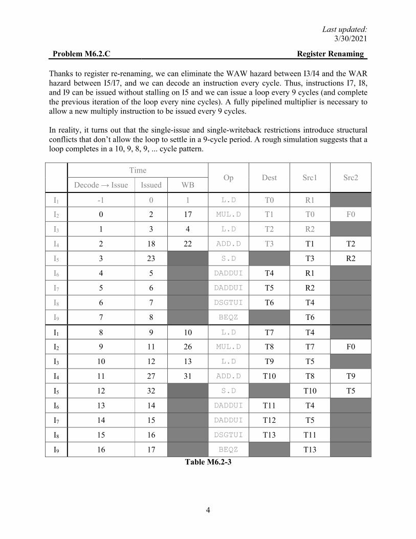
Problem M6.2.C Register Renaming Thanks to register re-renaming, we can eliminate the WAW hazard between I3/I4 and the WAR hazard between I5/I7, and we can decode an instruction every cycle. Thus, instructions I7, I8, and I9 can be issued without stalling on I5 and we can issue a loop every 9 cycles (and complete the previous iteration of the loop every nine cycles). A fully pipelined multiplier is necessary to allow a new multiply instruction to be issued every 9 cycles. In reality, it turns out that the single-issue and single-writeback restrictions introduce structural conflicts that don’t allow the loop to settle in a 9-cycle period. A rough simulation suggests that a loop completes in a 10, 9, 8, 9, ... cycle pattern.
Time
Op Dest Src1 Src2 Decode → Issue Issued WB
I1 -1 0 1 L.D T0 R1
I2 0 2 17 MUL.D T1 T0 F0
I3 1 3 4 L.D T2 R2
I4 2 18 22 ADD.D T3 T1 T2
I5 3 23 S.D T3 R2
I6 4 5 DADDUI T4 R1
I7 5 6 DADDUI T5 R2
I8 6 7 DSGTUI T6 T4
I9 7 8 BEQZ T6
I1 8 9 10 L.D T7 T4
I2 9 11 26 MUL.D T8 T7 F0
I3 10 12 13 L.D T9 T5
I4 11 27 31 ADD.D T10 T8 T9
I5 12 32 S.D T10 T5
I6 13 14 DADDUI T11 T4
I7 14 15 DADDUI T12 T5
I8 15 16 DSGTUI T13 T11
I9 16 17 BEQZ T13
Table M6.2-3
Last updated: 3/30/2021
5
Problem M6.3: Out-of-Order Scheduling Problem M6.3.A
This question is similar to Problem M6.2.C with shorter latency for the FPU.
(This is NOT a unified register file design. The register names (T0, T1, …etc) in the renaming table refer to the ROB tags. Since we have a two-entry ROB, we should only use T0 and T1 for the renaming.)
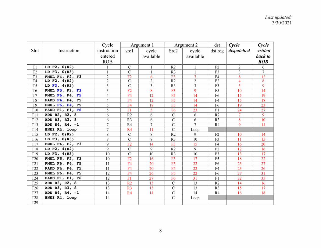
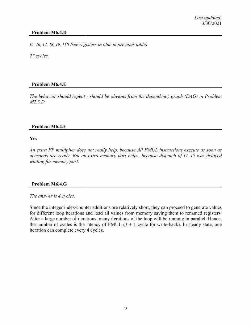
Problem M6.4.D I5, I6, I7, I8, I9, I10 (see registers in blue in previous table) 27 cycles. Problem M6.4.E
The behavior should repeat - should be obvious from the dependency graph (DAG) in Problem M2.3.D. Problem M6.4.F
Yes An extra FP multiplier does not really help, because All FMUL instructions execute as soon as operands are ready. But an extra memory port helps, because dispatch of I4, I5 was delayed waiting for memory port. Problem M6.4.G
The answer is 4 cycles. Since the integer index/counter additions are relatively short, they can proceed to generate values for different loop iterations and load all values from memory saving them to renamed registers. After a large number of iterations, many iterations of the loop will be running in parallel. Hence, the number of cycles is the latency of FMUL (3 + 1 cycle for write-back). In steady state, one iteration can complete every 4 cycles.
Last updated: 3/30/2021
10
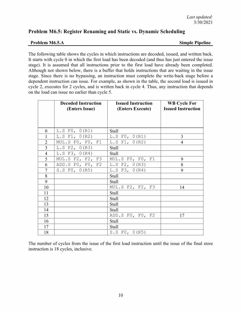
Problem M6.5: Register Renaming and Static vs. Dynamic Scheduling Problem M6.5.A Simple Pipeline The following table shows the cycles in which instructions are decoded, issued, and written back. It starts with cycle 0 in which the first load has been decoded (and thus has just entered the issue stage). It is assumed that all instructions prior to the first load have already been completed. Although not shown below, there is a buffer that holds instructions that are waiting in the issue stage. Since there is no bypassing, an instruction must complete the write-back stage before a dependent instruction can issue. For example, as shown in the table, the second load is issued in cycle 2, executes for 2 cycles, and is written back in cycle 4. Thus, any instruction that depends on the load can issue no earlier than cycle 5.
The number of cycles from the issue of the first load instruction until the issue of the final store instruction is 18 cycles, inclusive.
Last updated: 3/30/2021
11
Problem M6.5.B Static Scheduling The new code sequence is given below. Originally there were two stall cycles after the second load instruction. Now these cycles will be filled by the third and fourth load instructions. The remaining instructions cannot be reordered due to data dependencies (except for the two multiply instructions, although doing that would hurt performance). L.S F0, 0(R1) L.S F1, 0(R2) L.S F2, 0(R3) L.S F3, 0(R4) MUL.S F0, F0, F1 MUL.S F2, F2, F3 ADD.S F0, F0, F2 S.S F0, 0(R5) The following table shows the cycles in which the instructions in the above sequence are decoded, issued, and written back.
The number of cycles from the issue of the first load instruction to the issue of the final store instruction is 15 cycles, inclusive. Static scheduling has enabled us to reduce the execution time of the sequence by 17%.
Last updated: 3/30/2021
12
Problem M6.5.C Fewer Registers The new code sequence using only two floating-point registers is shown below. It is assumed that R6 holds the address of a memory location that can be used to store temporary values. L.S F0, 0(R1) L.S F1, 0(R2) MUL.S F0, F0, F1 L.S F1, 0(R3) S.S F0, 0(R6) L.S F0, 0(R4) MUL.S F0, F0, F1 L.S F1, 0(R6) ADD.S F0, F0, F1 S.S F0, 0(R5) The following table shows the cycles in which the instructions in the above sequence are decoded, issued, and written back. For this problem, a store instruction is needed in the middle of the instruction sequence in order to spill a register. Although not explicitly stated in the problem, stores have the same latency as loads (two cycles), since they use the same functional unit. Because the result of the store is not needed for several cycles after it completes (when the load restores the spilled value), it would take a very long latency for store instructions in order to delay the last load. We don’t have to worry about WAR hazards in the above sequence because instructions are issued in-order. Note that we can no longer execute the four original loads in sequence as in M3.4.B because of the lack of available registers. We can, however, execute the third load before saving the intermediate value from the first MUL instruction.
The number of cycles from the issue of the first load instruction to the issue of the final store instruction is 22 cycles, inclusive. The use of only two floating-point registers results in a severe performance hit.
Last updated: 3/30/2021
14
Problem M6.5.D Register renaming and dynamic scheduling The table below shows the cycles in which the instructions in the original code sequence are decoded, issued, and written back on the single-issue machine with register renaming and out-of-order issue. The table also contains the rename table for the architectural registers.
The number of cycles from the issue of the first load instruction to the issue of the final store instruction is 17 cycles, inclusive. This is one cycle better than executing this code on an in-order machine but not quite as good as the performance of the optimized code in M6.5.B, which only required 15 cycles. The difference in performance between the statically scheduled code and the dynamically scheduled code can be attributed to the fact that only a single instruction can be decoded at a time, which limits the hardware’s ability to find independent instructions to issue. The optimized version of the code from M6.5.B executing on this machine would not improve in performance over executing on an in-order machine – it would still take 15 cycles. Note, that in cycle 5, we would get better performance if we issued the final load instruction rather than the MUL instruction. The machine doesn’t know that, so it issues the instruction that entered the ROB first.
Last updated: 3/30/2021
15
Problem M6.5.E Effect of Register Spills
The table below shows the cycles in which the instructions in the original code sequence are decoded, issued, and written back on the single-issue machine with register renaming and out-of-order issue.
It now takes 22 cycles between issue of the first load instruction and issue of the last store instruction. That is the same performance as M6.5.C, and much worse than M6.5.D.
We managed to execute two instructions out of order, but we still couldn’t beat the in-order performance. The problem lies with the fact that we had to wait for the first store to issue before we could continue with the program. This is directly linked to having only two registers, thus having to store intermediate values.
Last updated: 3/30/2021
16
Problem M6.6: Register Renaming Schemes Problem M6.6.A Finding Operands: Original ROB scheme
Instruction Src1 value
Regfile, ROB, rename table, or instruction? Src2 value
Regfile, ROB, rename table, or instruction?
sub r5,r1,r3 1 Regfile t2 Rename table addi r6,r2,4 2 Regfile 4 Instruction andi r7,r4,3 4 ROB 3 Instruction
Problem M6.6.B Finding Operands: Future File Scheme
A source register operand for an instruction I can be in one of the following three possible states.
1. It can be produced by a previous instruction that has not yet completed, in which case I will get the tag from the rename table.
2. It can be produced by a previous instruction that has completed execution but has not yet written back to the register file. However, the previous instruction will have written the value to the future file in this case, so I can obtain the value from that structure.
3. It can be produced by a previous instruction that has committed its value to the register file, in which case I can simply read the value from the regfile.
None of the above scenarios requires I to fetch an operand from the ROB. Problem M6.6.C Future File Operation
An example code sequence is: LD R2, 0(R1) ADDI R3, R2, 1 SUB R4, R3, R5 ADD R3, R4, R6 An instruction result will be written to the ROB but not the future file if a subsequent instruction has been decoded and writes to the same destination register. To illustrate with the given example, since instruction decode occurs in order, the ADD instruction will be decoded after the ADDI instruction. Thus, the entry for R3 in the rename table will contain a tag for the ADD instruction after all of the above instructions have been decoded. Now suppose that the ADDI instruction completes execution after the ADD instruction is decoded. Because the tag for R3 will not match the tag for the ADDI instruction, the result of that instruction will not be written back to the future file, but it will be written back to the ROB.


![Pipelining & Parallel Processing - ics.kaist.ac.krics.kaist.ac.kr/ee878_2018f/[EE878]3 Pipelining and Parallel Processing.pdf · Pipelining processing By using pipelining latches](https://static.documents.pub/doc/80x56/5d40e26d88c99391748d47fb/pipelining-parallel-processing-icskaistackricskaistackree8782018fee8783.jpg)


