Disclaimer Procon Electronics makes no representations or warranties with respect to the contents hereof. In addition, information contained herein are subject to change without notice. Every precaution has been taken in the preparation of this manual. Nevertheless, Procon Electronics assumes no responsibility, express or implied, for errors or omissions or any damages resulting from the use of the information contained in this publication.
All trademarks belong to their respective owners.
PROCON ELECTRONICS 3 PROBUS
TABLE OF CONTENTS
1. AN OVERVIEW OF THE PROBUS SYSTEM ....................................................... 6
2. PROBUS GENERAL INFORMATION ................................................................. 9
2.1 PHYSICAL DIMENSIONS ................................................................................................................... 9 2.2 DIN RAIL BUS ADAPTOR ................................................................................................................ 10 2.3 INSTALLING THE MODULE ONTO THE DIN RAIL ................................................................................... 10 2.4 REMOVING THE MODULE FROM THE DIN RAIL ................................................................................... 11 2.5 GROUNDING/SHIELDING ............................................................................................................... 11 2.6 NETWORK TERMINATION .............................................................................................................. 11 2.7 RS485 NETWORK WIRING ............................................................................................................ 11 2.8 RS485 NETWORK PROTECTION ..................................................................................................... 13 2.9 SETTING THE MODBUS NODE ID .................................................................................................... 14
2.9.1 Changing the DIP switch to set the Node ID and baud rate ........................................... 14 2.9.2 DIP Switch Status Register. ............................................................................................. 14 2.9.3 Node ID Table ................................................................................................................. 15
PROBUS is an innovative modular I/O system which provides a simple low cost solution for distributed I/O requirements. The PROBUS system consists of stand-alone Digital and Analog Input and Output modules which are connected together on a RS485 two wire multi-drop network. The modules plug into a special bus connector which fits inside the DIN rail. The modules communicate using the MODBUS RTU protocol. A 32bit ARM CPU is used in the modules to provide high speed data processing and fast communications turnaround times. Multiple baud rates are selectable from 2400 to 115200 baud. All PROBUS modules plug directly onto an industry standard DIN rail. All modules have a minimum isolation of 1500VAC rms between the field and logic and all RS485 circuits are isolated. The modules have been equipped with status led’s which are used to indicate the status of the Inputs or outputs. This visual indication assists with fault finding and diagnostics.
1.2 Application Configurations
There are a number of different configurations in which the PROBUS modules may be used in a system. Some are listed as follows:
1.2.1 I/O Expansion.
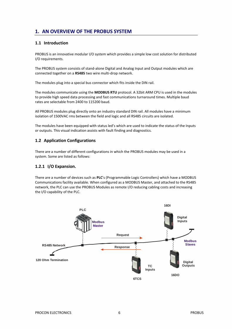
There are a number of devices such as PLC’s (Programmable Logic Controllers) which have a MODBUS Communications facility available. When configured as a MODBUS Master, and attached to the RS485 network, the PLC can use the PROBUS Modules as remote I/O reducing cabling costs and increasing the I/O capability of the PLC.
120 Ohm Termination
Modbus
Master
PLC
RS485 Network
DigitalOutputs
16DO
16DI
TCInputs
6TCS
Digital
Inputs
ModbusSlaves
Request
Response
PROCON ELECTRONICS 7 PROBUS
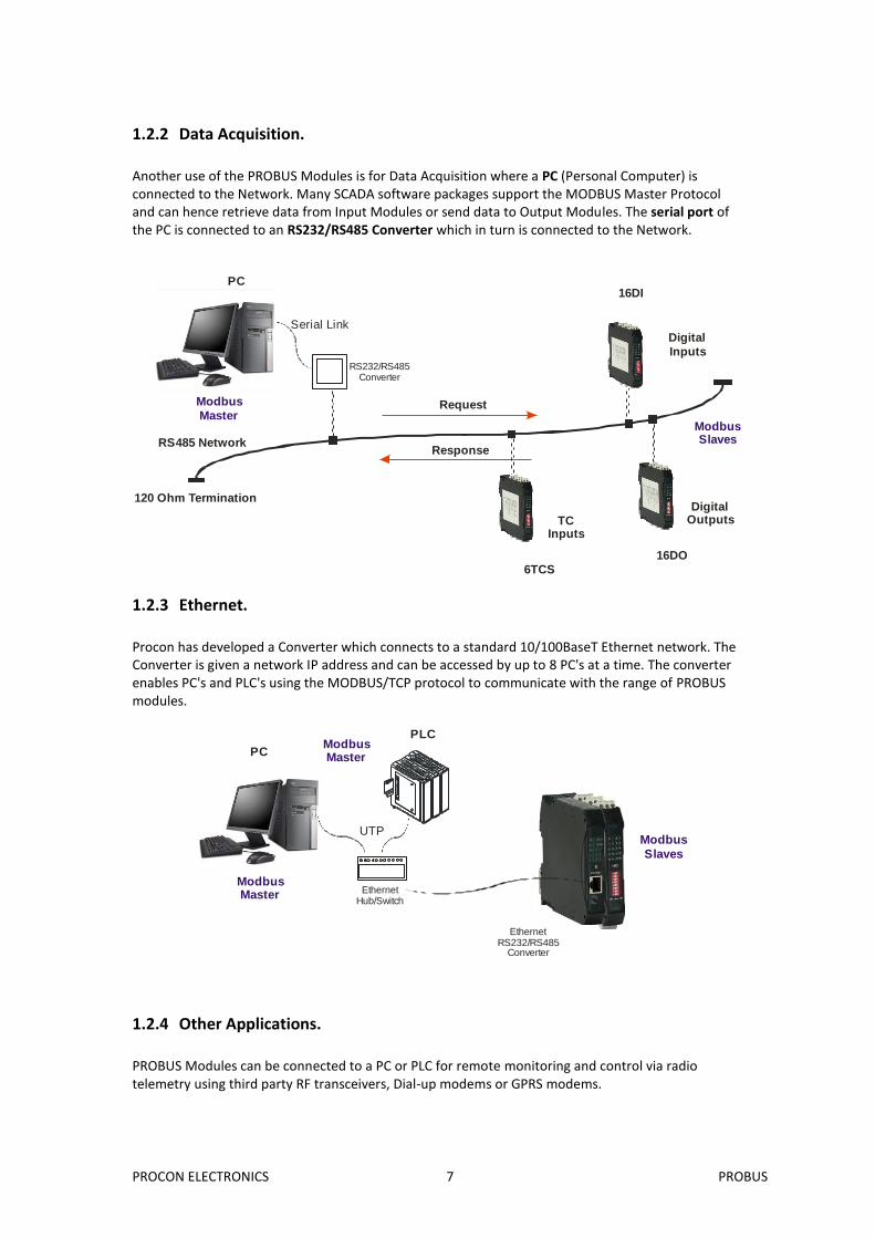
1.2.2 Data Acquisition.
Another use of the PROBUS Modules is for Data Acquisition where a PC (Personal Computer) is connected to the Network. Many SCADA software packages support the MODBUS Master Protocol and can hence retrieve data from Input Modules or send data to Output Modules. The serial port of the PC is connected to an RS232/RS485 Converter which in turn is connected to the Network.
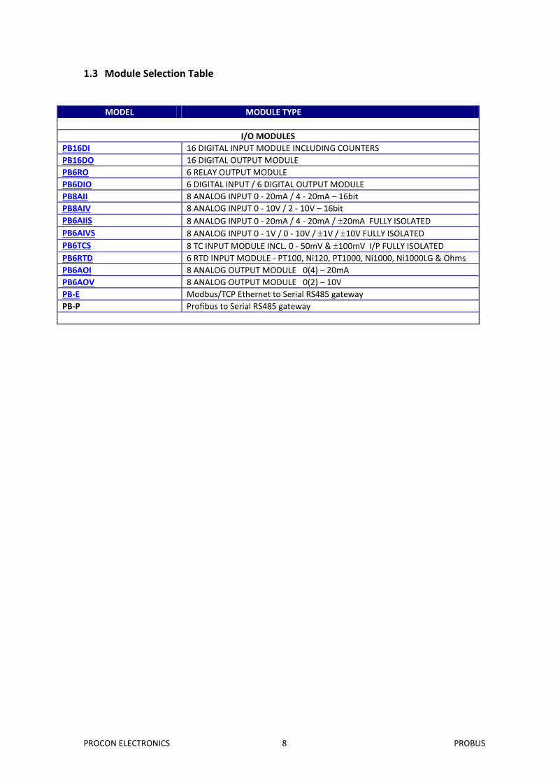
1.2.3 Ethernet.
Procon has developed a Converter which connects to a standard 10/100BaseT Ethernet network. The Converter is given a network IP address and can be accessed by up to 8 PC's at a time. The converter enables PC's and PLC's using the MODBUS/TCP protocol to communicate with the range of PROBUS modules.
1.2.4 Other Applications.
PROBUS Modules can be connected to a PC or PLC for remote monitoring and control via radio telemetry using third party RF transceivers, Dial-up modems or GPRS modems.
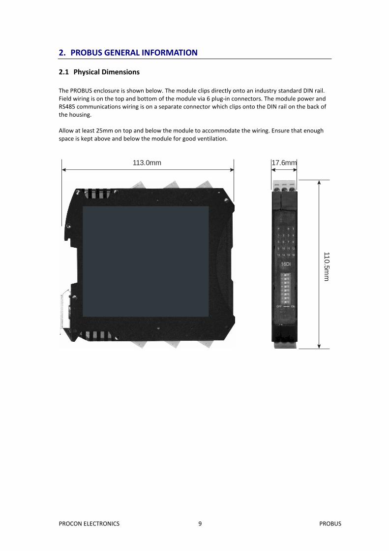
The PROBUS enclosure is shown below. The module clips directly onto an industry standard DIN rail. Field wiring is on the top and bottom of the module via 6 plug-in connectors. The module power and RS485 communications wiring is on a separate connector which clips onto the DIN rail on the back of the housing. Allow at least 25mm on top and below the module to accommodate the wiring. Ensure that enough space is kept above and below the module for good ventilation.
113.0mm 17.6mm
11
0.5
mm
PROCON ELECTRONICS 10 PROBUS
2.2 DIN rail Bus adaptor
The PROBUS connector allows side-by-side install of the Modules. The picture below shows multiple PROBUS connectors installed on a DIN rail. First, install the PROBUS connector onto the DIN rail, then slide into the adjacent PROBUS connector.
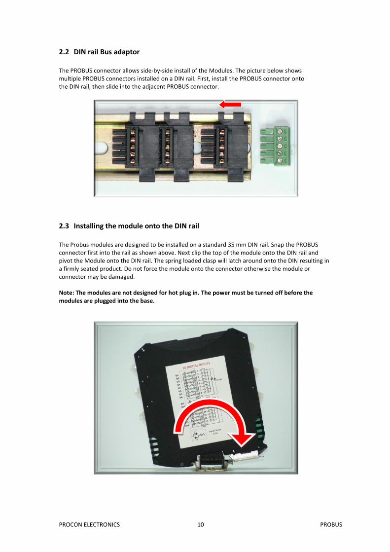
2.3 Installing the module onto the DIN rail
The Probus modules are designed to be installed on a standard 35 mm DIN rail. Snap the PROBUS connector first into the rail as shown above. Next clip the top of the module onto the DIN rail and pivot the Module onto the DIN rail. The spring loaded clasp will latch around onto the DIN resulting in a firmly seated product. Do not force the module onto the connector otherwise the module or connector may be damaged. Note: The modules are not designed for hot plug in. The power must be turned off before the modules are plugged into the base.
PROCON ELECTRONICS 11 PROBUS
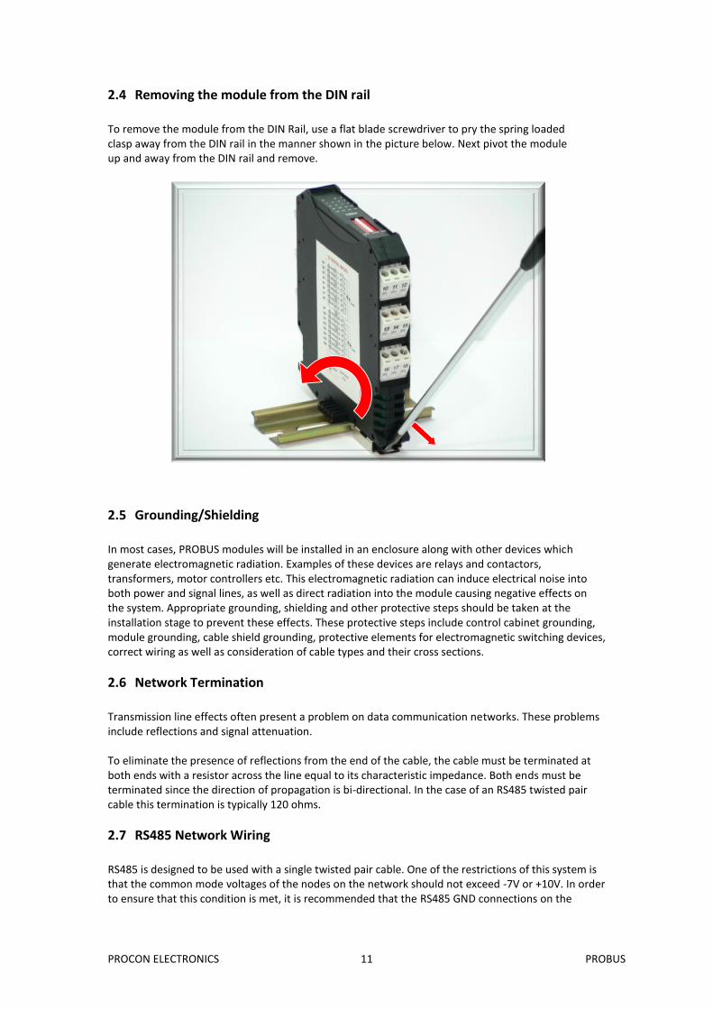
2.4 Removing the module from the DIN rail
To remove the module from the DIN Rail, use a flat blade screwdriver to pry the spring loaded clasp away from the DIN rail in the manner shown in the picture below. Next pivot the module up and away from the DIN rail and remove.
2.5 Grounding/Shielding
In most cases, PROBUS modules will be installed in an enclosure along with other devices which generate electromagnetic radiation. Examples of these devices are relays and contactors, transformers, motor controllers etc. This electromagnetic radiation can induce electrical noise into both power and signal lines, as well as direct radiation into the module causing negative effects on the system. Appropriate grounding, shielding and other protective steps should be taken at the installation stage to prevent these effects. These protective steps include control cabinet grounding, module grounding, cable shield grounding, protective elements for electromagnetic switching devices, correct wiring as well as consideration of cable types and their cross sections.
2.6 Network Termination
Transmission line effects often present a problem on data communication networks. These problems include reflections and signal attenuation. To eliminate the presence of reflections from the end of the cable, the cable must be terminated at both ends with a resistor across the line equal to its characteristic impedance. Both ends must be terminated since the direction of propagation is bi-directional. In the case of an RS485 twisted pair cable this termination is typically 120 ohms.
2.7 RS485 Network Wiring
RS485 is designed to be used with a single twisted pair cable. One of the restrictions of this system is that the common mode voltages of the nodes on the network should not exceed -7V or +10V. In order to ensure that this condition is met, it is recommended that the RS485 GND connections on the
PROCON ELECTRONICS 12 PROBUS
modules be connected together. For modules that are far apart, a second twisted pair should be used as the RS485 GND link. In certain applications where there are strong possibilities of an earth loop being caused by the RS485 GND link, the link should be tied to the RS485 GND terminal on each module through a 100ohm resistor, to limit the earth loop current. Where earth loop problems exist, it may be necessary to isolate the RS485 network either using optical fiber or an isolated RS485 repeater such as the PB485REP module.
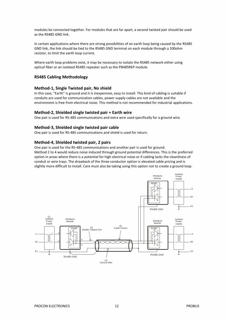
RS485 Cabling Methodology Method-1, Single Twisted pair, No shield In this case, “Earth” is ground and it is inexpensive, easy to install. This kind of cabling is suitable if conduits are used for communication cables, power supply cables are not available and the environment is free from electrical noise. This method is not recommended for industrial applications.
Method-2, Shielded single twisted pair + Earth wire One pair is used for RS-485 communications and extra wire used specifically for a ground wire.
Method-3, Shielded single twisted pair cable One pair is used for RS-485 communications and shield is used for return.
Method-4, Shielded twisted pair, 2 pairs One pair is used for the RS-485 communications and another pair is used for ground. Method 2 to 4 would reduce noise induced through ground potential differences. This is the preferred option in areas where there is a potential for high electrical noise or if cabling lacks the cleanliness of conduit or wire trays. The drawback of the three conductor option is elevated cable pricing and is slightly more difficult to install. Care must also be taking using this option not to create a ground loop.
RS485
PROBUSModule
(1)IsolatedPowersupply
RS485
PROBUSModule
IsolatedPowersupply
RS485
PROBUSModule
IsolatedPowersupply
L2
N2
E2
L3
N3
E3
L1
N1
E1
RS485 GND
(2)RS485 Twisted Pair
(4)Cable Screen
(3)Ground Wire
+
-
2
1
3
4
5
RS485 GND
RS485 GND
PROCON ELECTRONICS 13 PROBUS
Good installation practice for RS485 systems: 1. Use RS485 twisted cable to prevent electrical noise pickup. 2. Use a ground wire to connect all of the RS485 GND terminals on the modules together. This ensures that all of the modules are at the same potential. The ground wire must be earthed at one only. 3. Use a screened cable to prevent electrical noise pickup. This screen must be earthed at one end only. If a ground wire is not available then the screen can be used instead. To get the best performance this is not recommended. 4. The RS485 and power supply is wired correctly. 5. Do not carry RS485 and 24V DC power supply in same cables. 6. Use Separate isolated 24V DC for RS485 devices power supply and field inputs. 7. The 0V of the power supply must be earthed. 8. The screen of the RS485 cable must be earthed. 9. The RS485 devices must be at the same earth potential. 10. Use optical isolators in RS485 line to provide protection from low frequency interference from ground loops. 11. Do proper termination and/or shielding to provide isolation from high frequency interference, RFI, and transients. 12. The power supply must have good filters and protection on the 220V/110V side. 13. The RS485 line should have external over voltage protection to protect from high voltage electrical noise being induced into the RS485 cable. 14. Make sure there is a dedicated Instrumentation ground system to be used with RS485 devices.
2.8 RS485 Network Protection
Being used in an industrial environment, the RS485 network could pick up electrical noise from other machinery or even lightening. In this case it is advised that an RS485 network protection device be used at the entry point to the panel where the PROBUS modules are housed.
PROCON ELECTRONICS 14 PROBUS
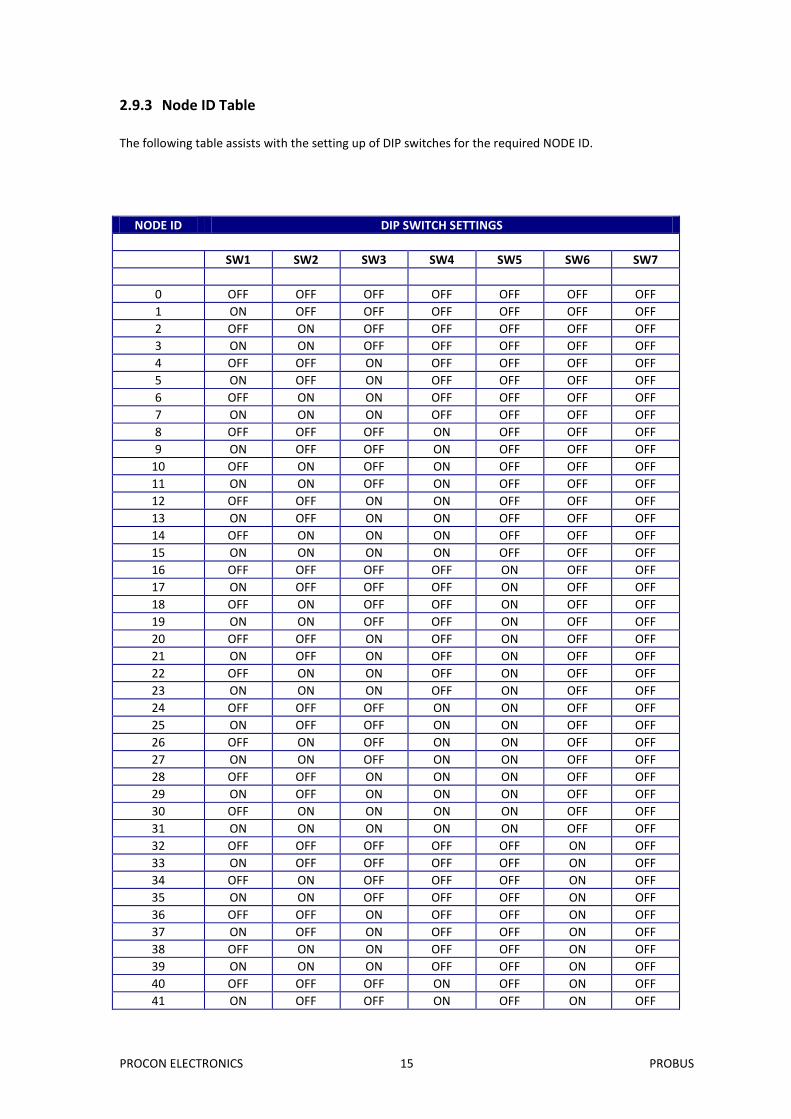
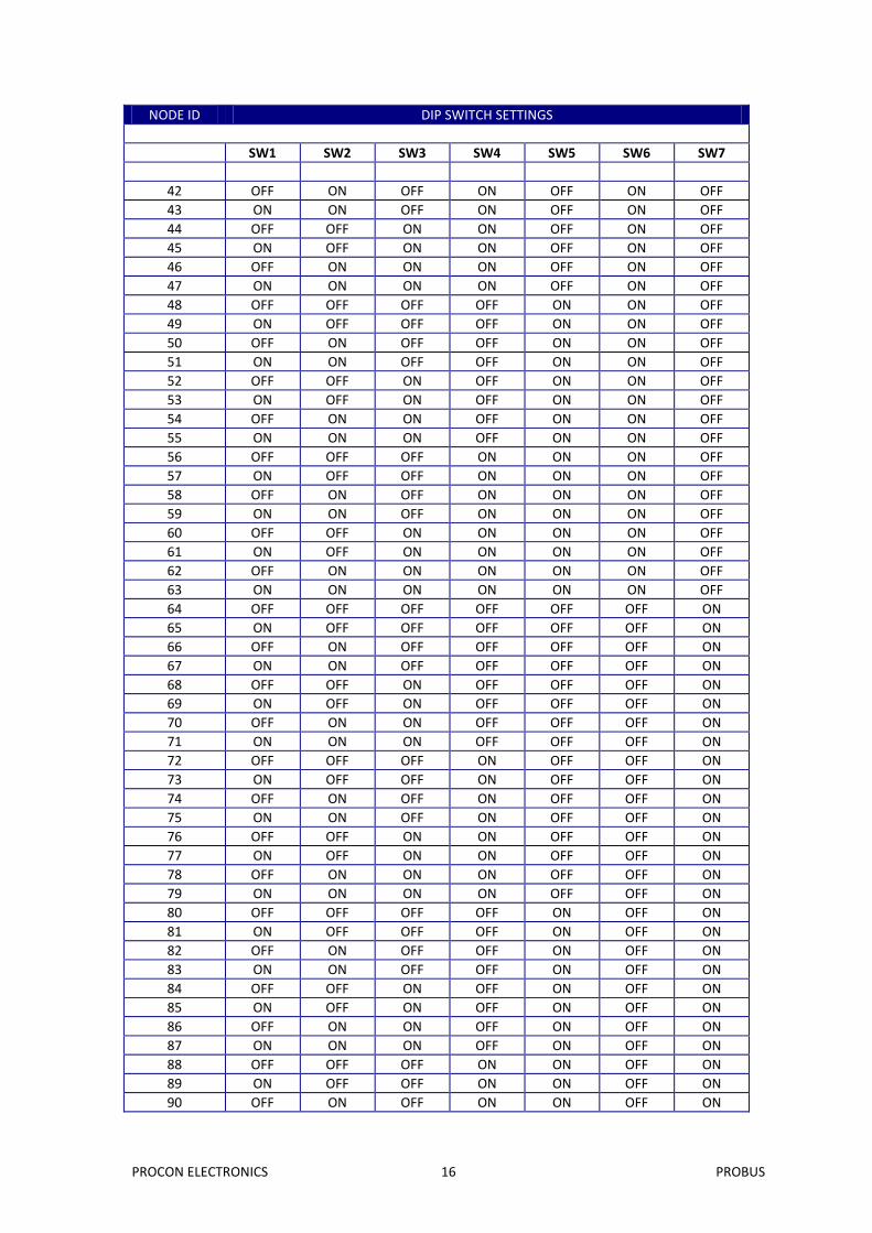
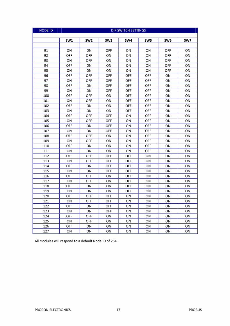
2.9 Setting the Modbus Node ID
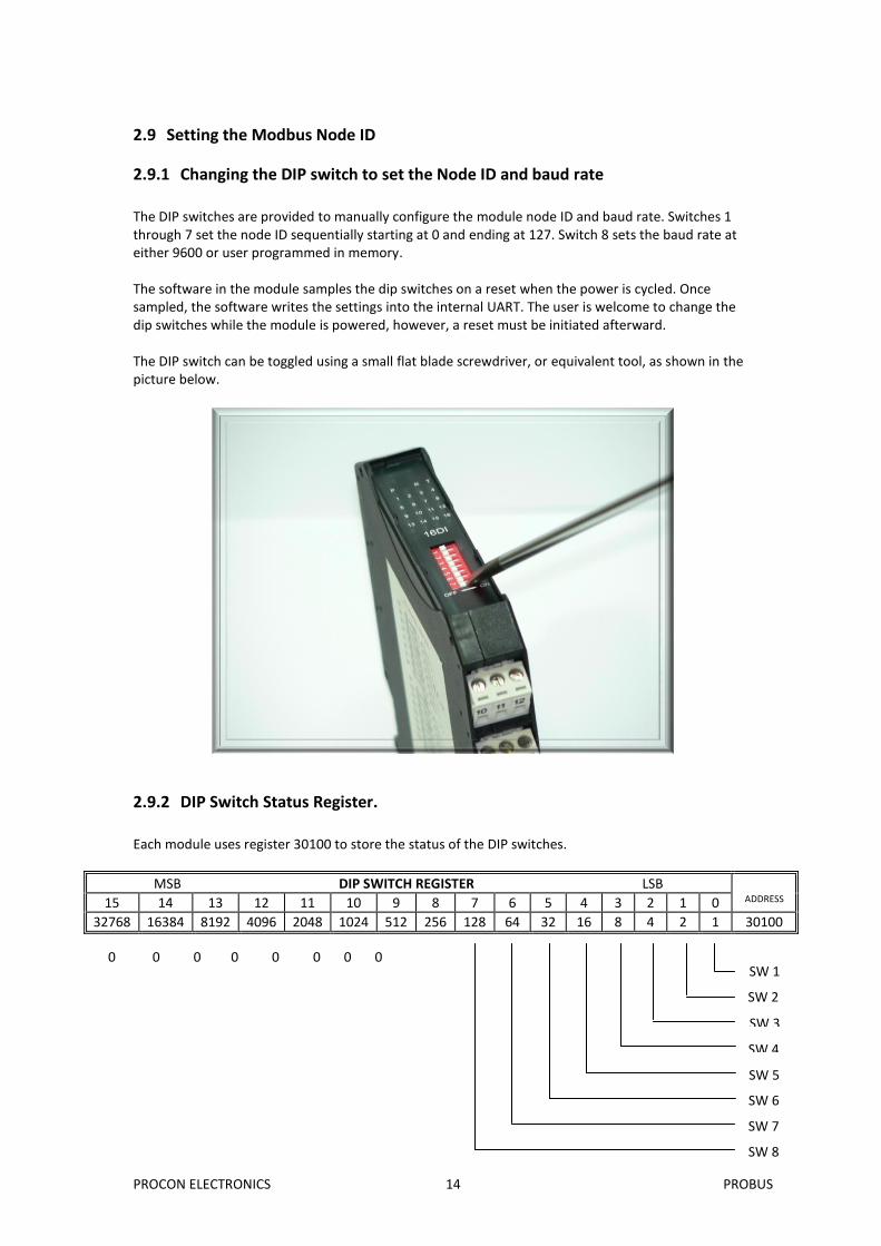
2.9.1 Changing the DIP switch to set the Node ID and baud rate
The DIP switches are provided to manually configure the module node ID and baud rate. Switches 1 through 7 set the node ID sequentially starting at 0 and ending at 127. Switch 8 sets the baud rate at either 9600 or user programmed in memory. The software in the module samples the dip switches on a reset when the power is cycled. Once sampled, the software writes the settings into the internal UART. The user is welcome to change the dip switches while the module is powered, however, a reset must be initiated afterward. The DIP switch can be toggled using a small flat blade screwdriver, or equivalent tool, as shown in the picture below.
2.9.2 DIP Switch Status Register.
Each module uses register 30100 to store the status of the DIP switches.
The baud rate value is programmed directly into the baud rate register. The only exception is the 115200 baud rate where the value 11520 is used and 187500 baud where the value 18750 is used.
2.10.3.2 Parity Register (40122)
The parity can be set to none by writing a 0 to the parity register, set to even by writing a 1 to the parity Register or set to odd by writing a 2 to the parity register.
2.10.3.3 Stop Bits Register (40123)
The number of stop bits can be set to 1 by writing a 1 to the stop bits register or set to 2 by writing a 2 to the stop bits Register.
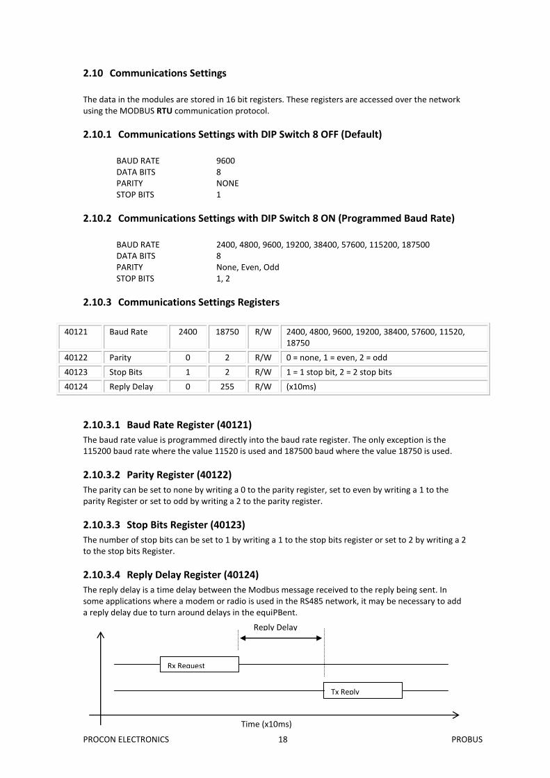
2.10.3.4 Reply Delay Register (40124)
The reply delay is a time delay between the Modbus message received to the reply being sent. In some applications where a modem or radio is used in the RS485 network, it may be necessary to add a reply delay due to turn around delays in the equiPBent.
Time (x10ms)
Reply Delay
Rx Request
Tx Reply
PROCON ELECTRONICS 19 PROBUS
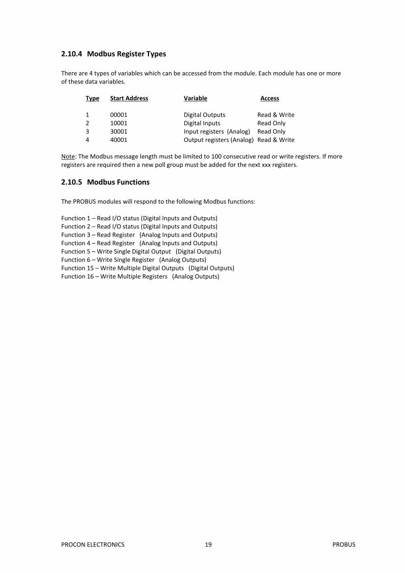
2.10.4 Modbus Register Types
There are 4 types of variables which can be accessed from the module. Each module has one or more of these data variables.
Type Start Address Variable Access 1 00001 Digital Outputs Read & Write 2 10001 Digital Inputs Read Only 3 30001 Input registers (Analog) Read Only 4 40001 Output registers (Analog) Read & Write
Note: The Modbus message length must be limited to 100 consecutive read or write registers. If more registers are required then a new poll group must be added for the next xxx registers.
2.10.5 Modbus Functions
The PROBUS modules will respond to the following Modbus functions: Function 1 – Read I/O status (Digital Inputs and Outputs) Function 2 – Read I/O status (Digital Inputs and Outputs) Function 3 – Read Register (Analog Inputs and Outputs) Function 4 – Read Register (Analog Inputs and Outputs) Function 5 – Write Single Digital Output (Digital Outputs) Function 6 – Write Single Register (Analog Outputs) Function 15 – Write Multiple Digital Outputs (Digital Outputs) Function 16 – Write Multiple Registers (Analog Outputs)
PROCON ELECTRONICS 20 PROBUS
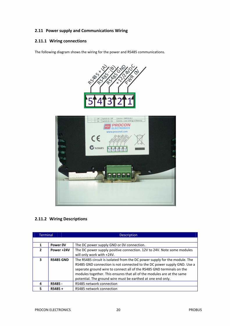
2.11 Power supply and Communications Wiring
2.11.1 Wiring connections
The following diagram shows the wiring for the power and RS485 communications.
4 3 2 15RS4
85 -
(B)
RS485
+ (A)
PWR 0
V
+12/2
4VD
C
RS485
GND
2.11.2 Wiring Descriptions
Terminal Description
1 Power 0V The DC power supply GND or 0V connection.
2 Power +24V The DC power supply positive connection. 12V to 24V. Note some modules will only work with +24V.
3 RS485 GND The RS485 circuit is isolated from the DC power supply for the module. The RS485 GND connection is not connected to the DC power supply GND. Use a seperate ground wire to connect all of the RS485 GND terminals on the modules together. This ensures that all of the modules are at the same potential. The ground wire must be earthed at one end only.
4 RS485 - RS485 network connection
5 RS485 + RS485 network connection
PROCON ELECTRONICS 21 PROBUS
3. PROBUS MODULES
3.1 PB16DI - DIGITAL INPUTS WITH COUNTERS
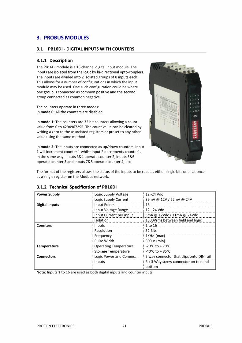
3.1.1 Description
The PB16DI module is a 16 channel digital input module. The inputs are isolated from the logic by bi-directional opto-couplers. The inputs are divided into 2 isolated groups of 8 inputs each. This allows for a number of configurations in which the input module may be used. One such configuration could be where one group is connected as common positive and the second group connected as common negative. The counters operate in three modes: In mode 0: All the counters are disabled. In mode 1: The counters are 32 bit counters allowing a count value from 0 to 4294967295. The count value can be cleared by writing a zero to the associated registers or preset to any other value using the same method. In mode 2: The inputs are connected as up/down counters. Input 1 will increment counter 1 whilst input 2 decrements counter1. In the same way, inputs 3&4 operate counter 2, inputs 5&6 operate counter 3 and inputs 7&8 operate counter 4, etc. The format of the registers allows the status of the inputs to be read as either single bits or all at once as a single register on the Modbus network.
3.1.2 Technical Specification of PB16DI
Power Supply Logic Supply Voltage 12 -24 Vdc
Logic Supply Current 39mA @ 12V / 22mA @ 24V
Digital Inputs Input Points 16
Input Voltage Range 12 - 24 Vdc
Input Current per input 5mA @ 12Vdc / 11mA @ 24Vdc
Isolation 1500Vrms between field and logic
Counters Inputs 1 to 16
Resolution 32 Bits
Frequency 1KHz (max)
Pulse Width 500us (min)
Temperature Operating Temperature. -20°C to + 70°C
Storage Temperature -40°C to + 85°C
Connectors Logic Power and Comms. 5 way connector that clips onto DIN rail
Inputs 6 x 3 Way screw connector on top and bottom
Note: Inputs 1 to 16 are used as both digital inputs and counter inputs.
PROCON ELECTRONICS 22 PROBUS
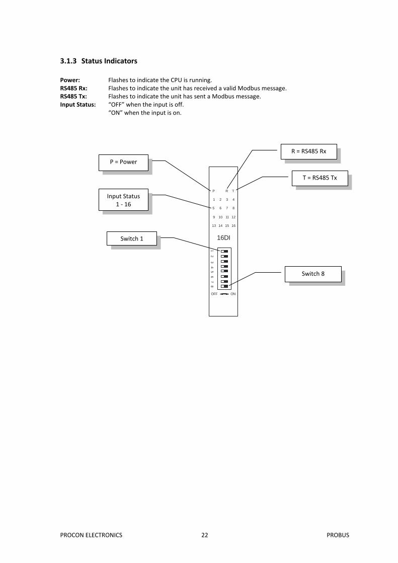
3.1.3 Status Indicators
Power: Flashes to indicate the CPU is running. RS485 Rx: Flashes to indicate the unit has received a valid Modbus message. RS485 Tx: Flashes to indicate the unit has sent a Modbus message. Input Status: “OFF” when the input is off.
“ON” when the input is on.
16DI
1 2 3 4
5 6 7 8
9 10 11 12
13 14 15 16
P R T
OFF ON
1 2
3 4 5
6 7
8
R = RS485 Rx
T = RS485 Tx
P = Power
Input Status 1 - 16
Switch 1
Switch 8
PROCON ELECTRONICS 23 PROBUS
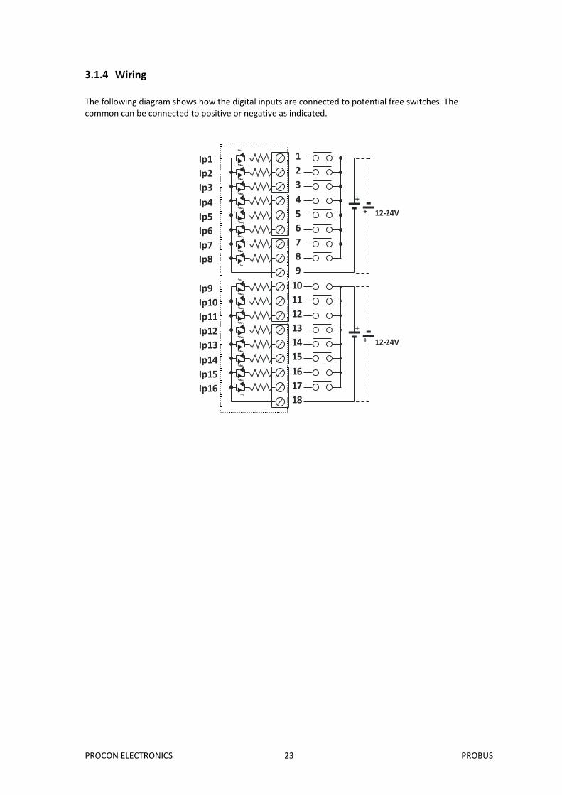
3.1.4 Wiring
The following diagram shows how the digital inputs are connected to potential free switches. The common can be connected to positive or negative as indicated.
1
2
3
4
5
6
7
8
9
10
11
12
13
14
15
16
17
18
+
12-24V
+
+
12-24V
+
Ip1
Ip2
Ip3
Ip4
Ip5
Ip6
Ip7
Ip8
Ip9
Ip10
Ip11
Ip12
Ip13
Ip14
Ip15
Ip16
PROCON ELECTRONICS 24 PROBUS
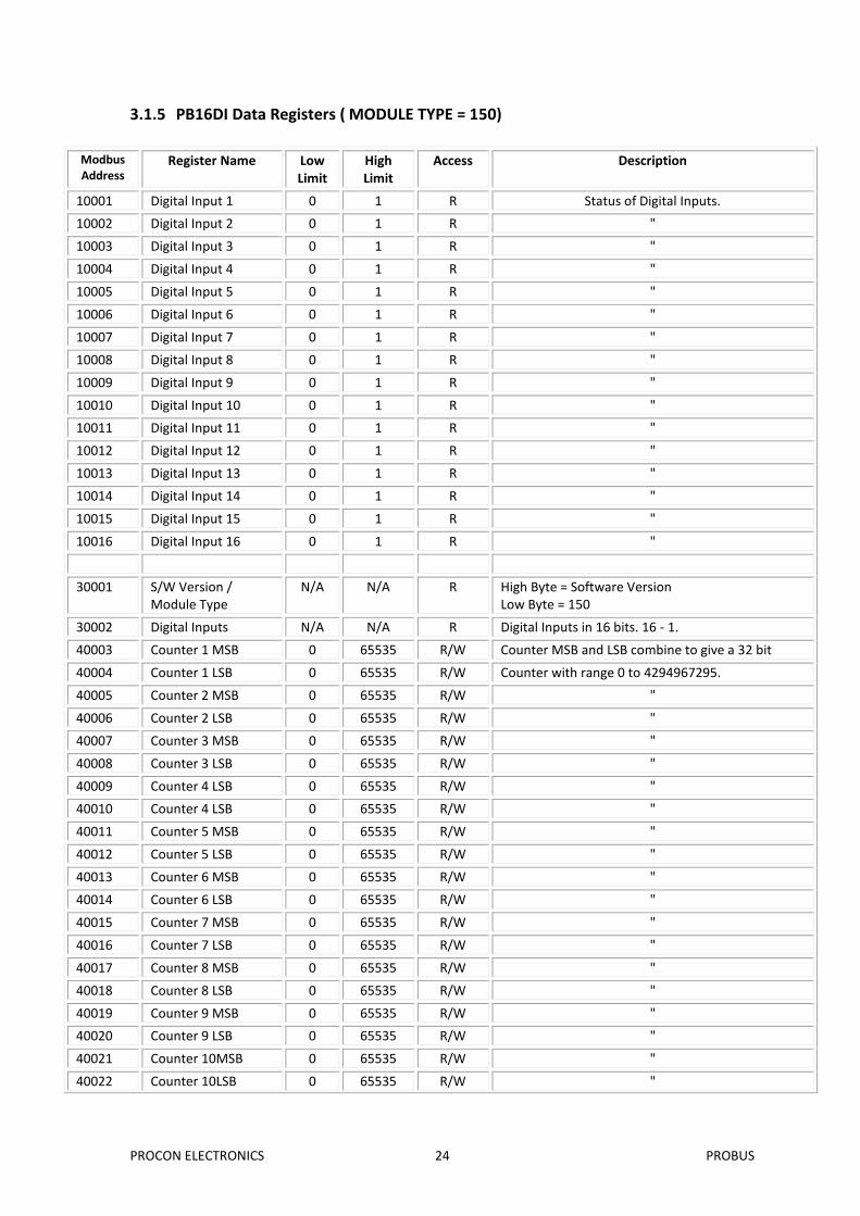
3.1.5 PB16DI Data Registers ( MODULE TYPE = 150)
Modbus Address
Register Name Low Limit
High Limit
Access Description
10001 Digital Input 1 0 1 R Status of Digital Inputs.
10002 Digital Input 2 0 1 R "
10003 Digital Input 3 0 1 R "
10004 Digital Input 4 0 1 R "
10005 Digital Input 5 0 1 R "
10006 Digital Input 6 0 1 R "
10007 Digital Input 7 0 1 R "
10008 Digital Input 8 0 1 R "
10009 Digital Input 9 0 1 R "
10010 Digital Input 10 0 1 R "
10011 Digital Input 11 0 1 R "
10012 Digital Input 12 0 1 R "
10013 Digital Input 13 0 1 R "
10014 Digital Input 14 0 1 R "
10015 Digital Input 15 0 1 R "
10016 Digital Input 16 0 1 R "
30001 S/W Version / Module Type
N/A N/A R High Byte = Software Version Low Byte = 150
30002 Digital Inputs N/A N/A R Digital Inputs in 16 bits. 16 - 1.
40003 Counter 1 MSB 0 65535 R/W Counter MSB and LSB combine to give a 32 bit
40004 Counter 1 LSB 0 65535 R/W Counter with range 0 to 4294967295.
40005 Counter 2 MSB 0 65535 R/W "
40006 Counter 2 LSB 0 65535 R/W "
40007 Counter 3 MSB 0 65535 R/W "
40008 Counter 3 LSB 0 65535 R/W "
40009 Counter 4 LSB 0 65535 R/W "
40010 Counter 4 LSB 0 65535 R/W "
40011 Counter 5 MSB 0 65535 R/W "
40012 Counter 5 LSB 0 65535 R/W "
40013 Counter 6 MSB 0 65535 R/W "
40014 Counter 6 LSB 0 65535 R/W "
40015 Counter 7 MSB 0 65535 R/W "
40016 Counter 7 LSB 0 65535 R/W "
40017 Counter 8 MSB 0 65535 R/W "
40018 Counter 8 LSB 0 65535 R/W "
40019 Counter 9 MSB 0 65535 R/W "
40020 Counter 9 LSB 0 65535 R/W "
40021 Counter 10MSB 0 65535 R/W "
40022 Counter 10LSB 0 65535 R/W "
PROCON ELECTRONICS 25 PROBUS
Modbus Address
Register Name Low Limit
High Limit
Access Description
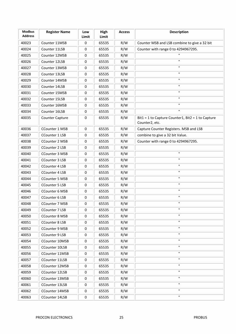
40023 Counter 11MSB 0 65535 R/W Counter MSB and LSB combine to give a 32 bit
40024 Counter 11LSB 0 65535 R/W Counter with range 0 to 4294967295.
40025 Counter 12MSB 0 65535 R/W "
40026 Counter 12LSB 0 65535 R/W "
40027 Counter 13MSB 0 65535 R/W "
40028 Counter 13LSB 0 65535 R/W "
40029 Counter 14MSB 0 65535 R/W "
40030 Counter 14LSB 0 65535 R/W "
40031 Counter 15MSB 0 65535 R/W "
40032 Counter 15LSB 0 65535 R/W "
40033 Counter 16MSB 0 65535 R/W "
40034 Counter 16LSB 0 65535 R/W "
40035 Counter Capture 0 65535 R/W Bit1 = 1 to Capture Counter1, Bit2 = 1 to Capture Counter2, etc.
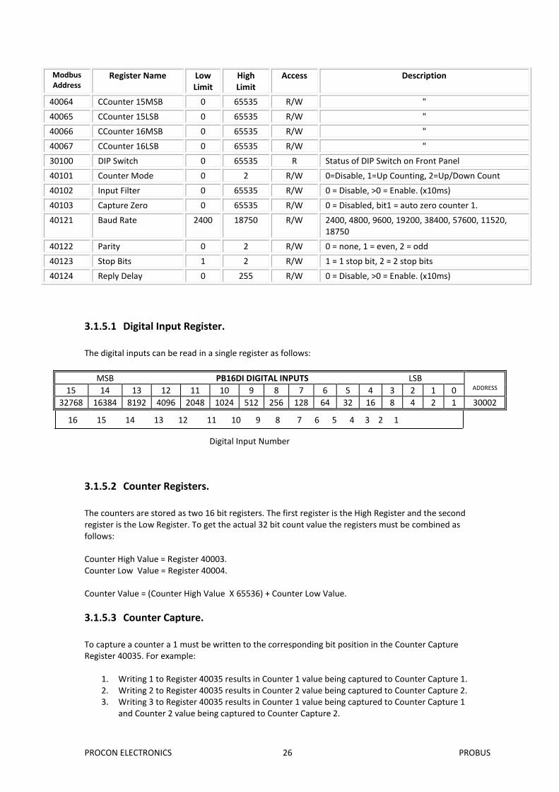
The counters are stored as two 16 bit registers. The first register is the High Register and the second register is the Low Register. To get the actual 32 bit count value the registers must be combined as follows: Counter High Value = Register 40003. Counter Low Value = Register 40004. Counter Value = (Counter High Value X 65536) + Counter Low Value.
3.1.5.3 Counter Capture.
To capture a counter a 1 must be written to the corresponding bit position in the Counter Capture Register 40035. For example:
1. Writing 1 to Register 40035 results in Counter 1 value being captured to Counter Capture 1. 2. Writing 2 to Register 40035 results in Counter 2 value being captured to Counter Capture 2. 3. Writing 3 to Register 40035 results in Counter 1 value being captured to Counter Capture 1
and Counter 2 value being captured to Counter Capture 2.
Digital Input Number
16 15 14 13 12 11 10 9 8 7 6 5 4 3 2 1
PROCON ELECTRONICS 27 PROBUS
Once the module has Captured the counters, the Counter Capture Register 40035 is cleared to zero. It is possible to read this register to get confirmation that the capture is complete before reading the captured counter values.
3.1.5.4 Counter Auto Zero.
The counter being captured can be auto zeroed. The purpose of this function is to let the module zero the counter so that no counts get lost due to delays from communication latency, etc. To ensure that a counter is auto zeroed, a 1 must be written to the corresponding bit position in the Capture Zero Register 40103. For example: Writing 1 to Register 40103 results in Counter 1 value being zeroed when the Counter Capture bit is 1. The value in the Capture Zero Register 40103 is permanently stored in memory and only has to be configured once.
PROCON ELECTRONICS 28 PROBUS
3.2 PB16DO - DIGITAL OUTPUTS
3.2.1 Description
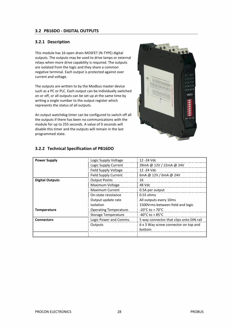
This module has 16 open drain MOSFET (N-TYPE) digital outputs. The outputs may be used to drive lamps or external relays when more drive capability is required. The outputs are isolated from the logic and they share a common negative terminal. Each output is protected against over current and voltage. The outputs are written to by the Modbus master device such as a PC or PLC. Each output can be individually switched on or off, or all outputs can be set up at the same time by writing a single number to the output register which represents the status of all outputs. An output watchdog timer can be configured to switch off all the outputs if there has been no communications with the module for up to 255 seconds. A value of 0 seconds will disable this timer and the outputs will remain in the last programmed state.
3.2.2 Technical Specification of PB16DO
Power Supply Logic Supply Voltage 12 -24 Vdc
Logic Supply Current 39mA @ 12V / 22mA @ 24V
Field Supply Voltage 12 -24 Vdc
Field Supply Current 6mA @ 12V / 6mA @ 24V
Digital Outputs Output Points 16
Maximum Voltage 48 Vdc
Maximum Current 0.5A per output
On-state resistance 0.55 ohms
Output update rate All outputs every 10ms
Isolation 1500Vrms between field and logic
Temperature Operating Temperature. -20°C to + 70°C
Storage Temperature -40°C to + 85°C
Connectors Logic Power and Comms. 5 way connector that clips onto DIN rail
Outputs 6 x 3 Way screw connector on top and bottom
PROCON ELECTRONICS 29 PROBUS
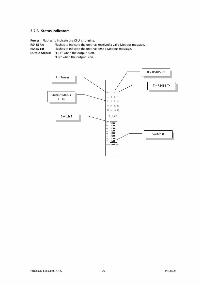
3.2.3 Status Indicators
Power: Flashes to indicate the CPU is running. RS485 Rx: Flashes to indicate the unit has received a valid Modbus message. RS485 Tx: Flashes to indicate the unit has sent a Modbus message. Output Status: “OFF” when the output is off.
“ON” when the output is on.
16DO
1 2 3 4
5 6 7 8
9 10 11 12
13 14 15 16
P R T
OFF ON
1 2
3 4 5
6 7
8
R = RS485 Rx
T = RS485 Tx
P = Power
Output Status 1 - 16
Switch 1
Switch 8
PROCON ELECTRONICS 30 PROBUS
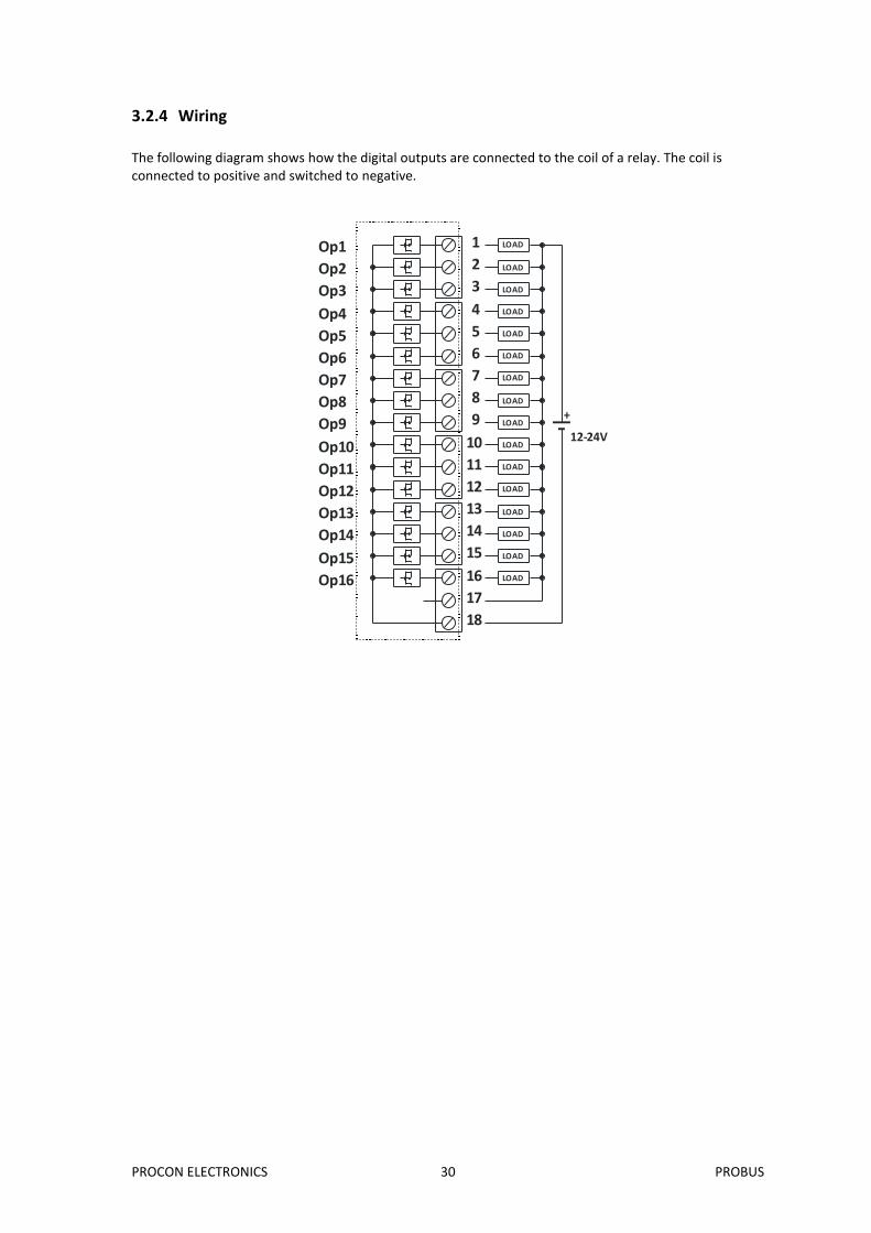
3.2.4 Wiring
The following diagram shows how the digital outputs are connected to the coil of a relay. The coil is connected to positive and switched to negative.
12-24V
LOAD
LOAD
LOAD
LOAD
LOAD
LOAD
LOAD
LOAD
LOAD
LOAD
LOAD
LOAD
LOAD
LOAD
LOAD
LOAD
+
1
2
3
4
5
6
7
8
9
10
11
12
13
14
15
16
17
18
Op1
Op2
Op3
Op4
Op5
Op6
Op7
Op8
Op9
Op10
Op11
Op12
Op13
Op14
Op15
Op16
PROCON ELECTRONICS 31 PROBUS
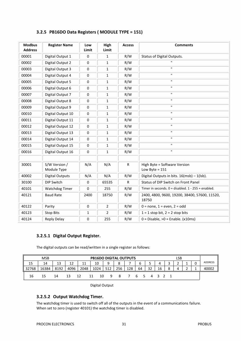
3.2.5 PB16DO Data Registers ( MODULE TYPE = 151)
Modbus Address
Register Name Low Limit
High Limit
Access Comments
00001 Digital Output 1 0 1 R/W Status of Digital Outputs.
00002 Digital Output 2 0 1 R/W "
00003 Digital Output 3 0 1 R/W "
00004 Digital Output 4 0 1 R/W "
00005 Digital Output 5 0 1 R/W "
00006 Digital Output 6 0 1 R/W "
00007 Digital Output 7 0 1 R/W "
00008 Digital Output 8 0 1 R/W "
00009 Digital Output 9 0 1 R/W "
00010 Digital Output 10 0 1 R/W "
00011 Digital Output 11 0 1 R/W "
00012 Digital Output 12 0 1 R/W "
00013 Digital Output 13 0 1 R/W "
00014 Digital Output 14 0 1 R/W "
00015 Digital Output 15 0 1 R/W "
00016 Digital Output 16 0 1 R/W "
30001 S/W Version / Module Type
N/A N/A R High Byte = Software Version Low Byte = 151
40002 Digital Outputs N/A N/A R/W Digital Outputs in bits. 16(msb) – 1(lsb).
30100 DIP Switch 0 65535 R Status of DIP Switch on Front Panel
The watchdog timer is used to switch off all of the outputs in the event of a communications failure. When set to zero (register 40101) the watchdog timer is disabled.
Digital Output Number
16 15 14 13 12 11 10 9 8 7 6 5 4 3 2 1
PROCON ELECTRONICS 32 PROBUS
3.3 PB6RO - RELAY OUTPUTS
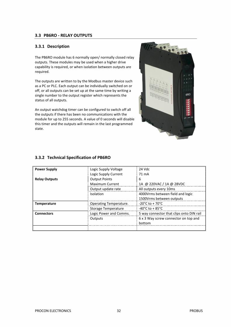
3.3.1 Description
The PB6RO module has 6 normally open/ normally closed relay outputs. These modules may be used when a higher drive capability is required, or when isolation between outputs are required. The outputs are written to by the Modbus master device such as a PC or PLC. Each output can be individually switched on or off, or all outputs can be set up at the same time by writing a single number to the output register which represents the status of all outputs. An output watchdog timer can be configured to switch off all the outputs if there has been no communications with the module for up to 255 seconds. A value of 0 seconds will disable this timer and the outputs will remain in the last programmed state.
3.3.2 Technical Specification of PB6RO
Power Supply Logic Supply Voltage 24 Vdc
Logic Supply Current 71 mA
Relay Outputs Output Points 6
Maximum Current 1A @ 220VAC / 1A @ 28VDC
Output update rate All outputs every 10ms
Isolation 4000Vrms between field and logic 1500Vrms between outputs
Temperature Operating Temperature. -20°C to + 70°C
Storage Temperature -40°C to + 85°C
Connectors Logic Power and Comms. 5 way connector that clips onto DIN rail
Outputs 6 x 3 Way screw connector on top and bottom
PROCON ELECTRONICS 33 PROBUS
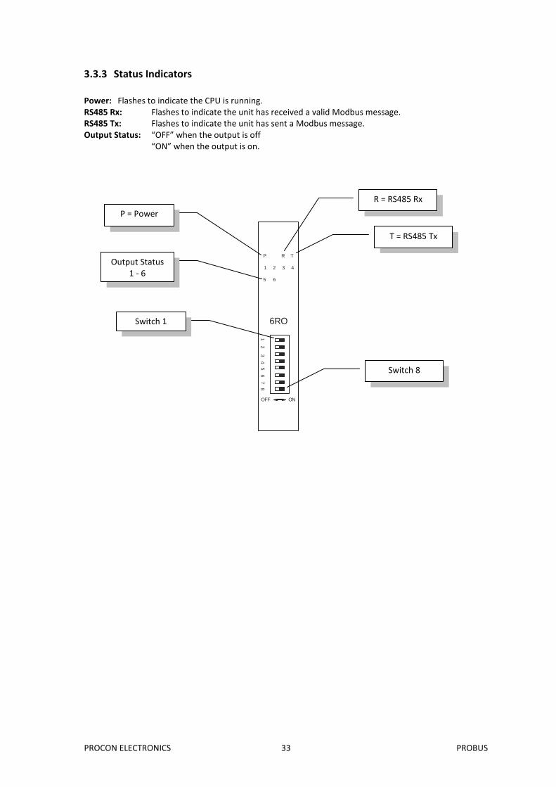
3.3.3 Status Indicators
Power: Flashes to indicate the CPU is running. RS485 Rx: Flashes to indicate the unit has received a valid Modbus message. RS485 Tx: Flashes to indicate the unit has sent a Modbus message. Output Status: “OFF” when the output is off
“ON” when the output is on.
6RO
1 2 3 4
5 6
P R T
OFF ON
1 2
3 4 5
6 7
8
R = RS485 Rx
T = RS485 Tx
P = Power
Output Status 1 - 6
Switch 1
Switch 8
PROCON ELECTRONICS 34 PROBUS
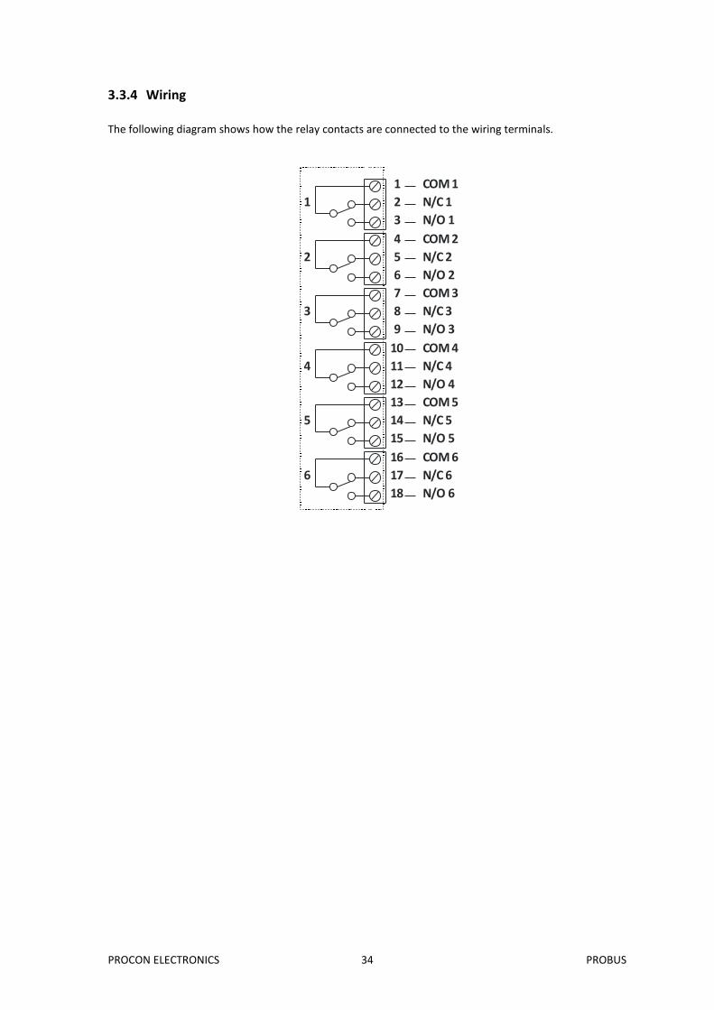
3.3.4 Wiring
The following diagram shows how the relay contacts are connected to the wiring terminals.
COM 1
N/C 1
N/O 1
COM 2
N/C 2
N/O 2
COM 3
N/C 3
N/O 3
COM 4
N/C 4
N/O 4
COM 5
N/C 5
N/O 5
COM 6
N/C 6
N/O 6
1
2
3
4
5
6
7
8
9
10
11
12
13
14
15
16
17
18
1
2
3
4
6
5
PROCON ELECTRONICS 35 PROBUS
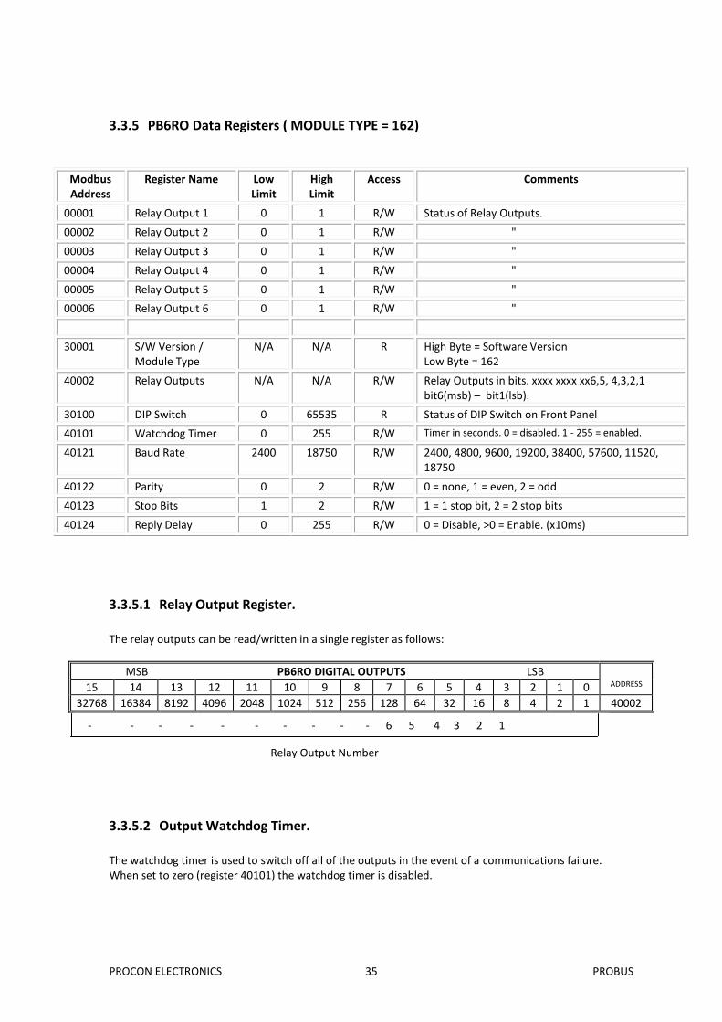
3.3.5 PB6RO Data Registers ( MODULE TYPE = 162)
Modbus Address
Register Name Low Limit
High Limit
Access Comments
00001 Relay Output 1 0 1 R/W Status of Relay Outputs.
00002 Relay Output 2 0 1 R/W "
00003 Relay Output 3 0 1 R/W "
00004 Relay Output 4 0 1 R/W "
00005 Relay Output 5 0 1 R/W "
00006 Relay Output 6 0 1 R/W "
30001 S/W Version / Module Type
N/A N/A R High Byte = Software Version Low Byte = 162
The watchdog timer is used to switch off all of the outputs in the event of a communications failure. When set to zero (register 40101) the watchdog timer is disabled.
Relay Output Number
- - - - - - - - - - 6 5 4 3 2 1
PROCON ELECTRONICS 36 PROBUS
3.4 PB6DIO - DIGITAL INPUTS / OUTPUTS
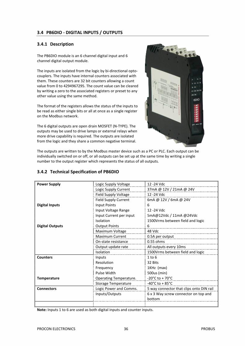
3.4.1 Description
The PB6DIO module is an 6 channel digital input and 6 channel digital output module. The inputs are isolated from the logic by bi-directional opto-couplers. The inputs have internal counters associated with them. These counters are 32 bit counters allowing a count value from 0 to 4294967295. The count value can be cleared by writing a zero to the associated registers or preset to any other value using the same method. The format of the registers allows the status of the inputs to be read as either single bits or all at once as a single register on the Modbus network. The 6 digital outputs are open drain MOSFET (N-TYPE). The outputs may be used to drive lamps or external relays when more drive capability is required. The outputs are isolated from the logic and they share a common negative terminal. The outputs are written to by the Modbus master device such as a PC or PLC. Each output can be individually switched on or off, or all outputs can be set up at the same time by writing a single number to the output register which represents the status of all outputs.
3.4.2 Technical Specification of PB6DIO
Power Supply Logic Supply Voltage 12 -24 Vdc
Logic Supply Current 37mA @ 12V / 21mA @ 24V
Field Supply Voltage 12 -24 Vdc
Field Supply Current 6mA @ 12V / 6mA @ 24V
Digital Inputs Input Points 6
Input Voltage Range 12 -24 Vdc
Input Current per input 5mA@12Vdc / 11mA @24Vdc
Isolation 1500Vrms between field and logic
Digital Outputs Output Points 6
Maximum Voltage 48 Vdc
Maximum Current 0.5A per output
On-state resistance 0.55 ohms
Output update rate All outputs every 10ms
Isolation 1500Vrms between field and logic
Counters Inputs 1 to 6
Resolution 32 Bits
Frequency 1KHz (max)
Pulse Width 500us (min)
Temperature Operating Temperature. -20°C to + 70°C
Storage Temperature -40°C to + 85°C
Connectors Logic Power and Comms. 5 way connector that clips onto DIN rail
Inputs/Outputs 6 x 3 Way screw connector on top and bottom
Note: Inputs 1 to 6 are used as both digital inputs and counter inputs.
PROCON ELECTRONICS 37 PROBUS
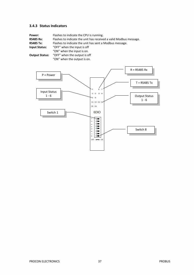
3.4.3 Status Indicators
Power: Flashes to indicate the CPU is running. RS485 Rx: Flashes to indicate the unit has received a valid Modbus message. RS485 Tx: Flashes to indicate the unit has sent a Modbus message. Input Status: “OFF” when the input is off
“ON” when the input is on. Output Status: “OFF” when the output is off
“ON” when the output is on.
6DIO
OFF ON
1 2
3 4 5
6 7
8
I1 I2 I3 I4
I5 I6
O1 O2 O3 O4
O5 O6
P R T
R = RS485 Rx
T = RS485 Tx
P = Power
Input Status 1 - 6
Switch 1
Switch 8
Output Status 1 - 6
PROCON ELECTRONICS 38 PROBUS
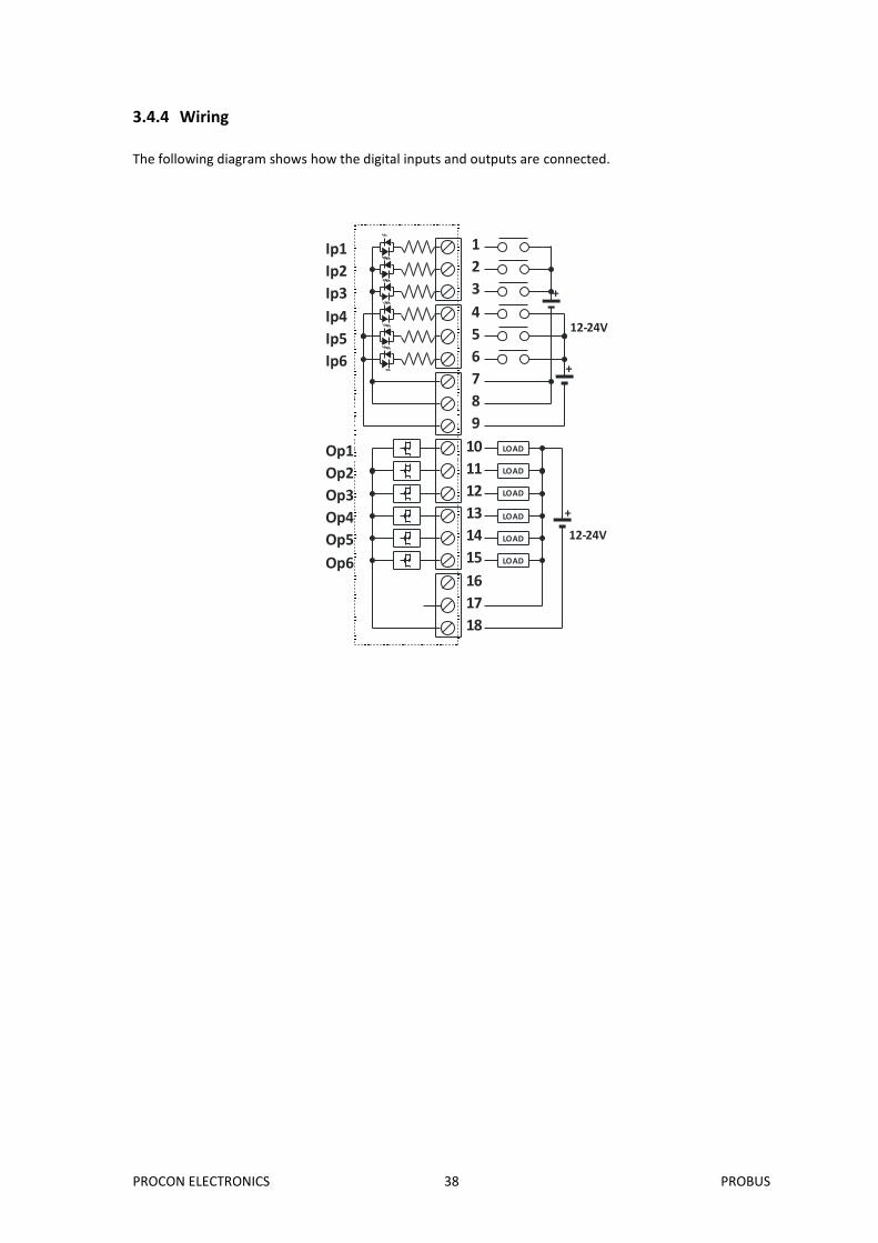
3.4.4 Wiring
The following diagram shows how the digital inputs and outputs are connected.
LOAD
LOAD
LOAD
LOAD
LOAD
LOAD
+
12-24V
12-24V
1
2
3
4
5
6
7
8
9
10
11
12
13
14
15
16
17
18
+
+
Op1
Op2
Op3
Op4
Op5
Op6
Ip1
Ip2
Ip3
Ip4
Ip5
Ip6
PROCON ELECTRONICS 39 PROBUS
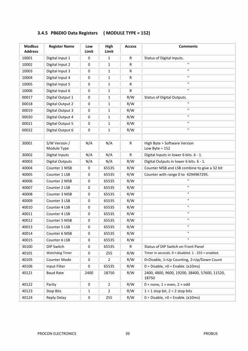
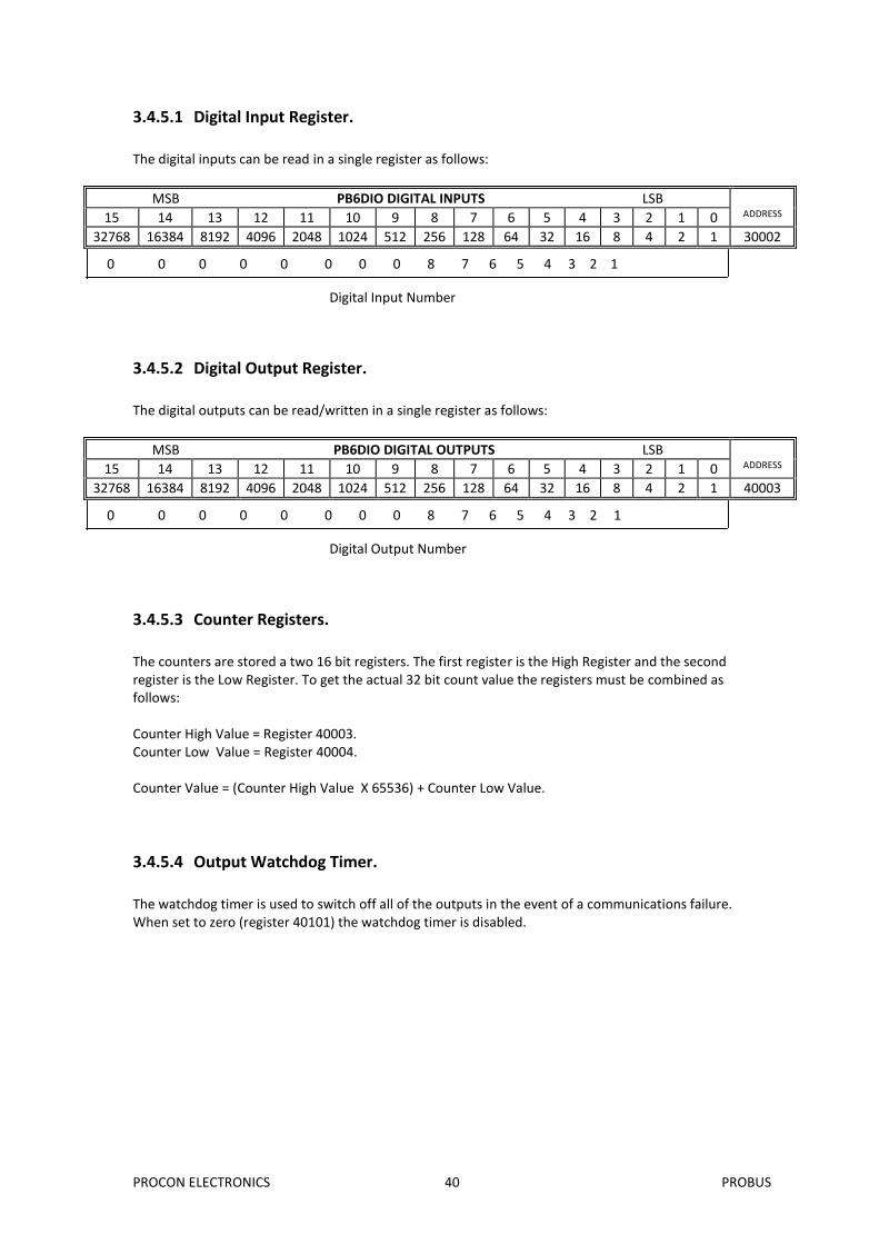
3.4.5 PB6DIO Data Registers ( MODULE TYPE = 152)
Modbus Address
Register Name Low Limit
High Limit
Access Comments
10001 Digital Input 1 0 1 R Status of Digital Inputs.
10002 Digital Input 2 0 1 R "
10003 Digital Input 3 0 1 R "
10004 Digital Input 4 0 1 R "
10005 Digital Input 5 0 1 R "
10006 Digital Input 6 0 1 R "
00017 Digital Output 1 0 1 R/W Status of Digital Outputs.
00018 Digital Output 2 0 1 R/W "
00019 Digital Output 3 0 1 R/W "
00020 Digital Output 4 0 1 R/W "
00021 Digital Output 5 0 1 R/W "
00022 Digital Output 6 0 1 R/W "
30001 S/W Version / Module Type
N/A N/A R High Byte = Software Version Low Byte = 152
30002 Digital Inputs N/A N/A R Digital Inputs in lower 6 bits. 6 - 1.
40003 Digital Outputs N/A N/A R/W Digital Outputs in lower 6 bits. 6 - 1.
40004 Counter 1 MSB 0 65535 R/W Counter MSB and LSB combine to give a 32 bit
40005 Counter 1 LSB 0 65535 R/W Counter with range 0 to 4294967295.
40006 Counter 2 MSB 0 65535 R/W "
40007 Counter 2 LSB 0 65535 R/W "
40008 Counter 3 MSB 0 65535 R/W "
40009 Counter 3 LSB 0 65535 R/W "
40010 Counter 4 LSB 0 65535 R/W "
40011 Counter 4 LSB 0 65535 R/W "
40012 Counter 5 MSB 0 65535 R/W "
40013 Counter 5 LSB 0 65535 R/W "
40014 Counter 6 MSB 0 65535 R/W "
40015 Counter 6 LSB 0 65535 R/W "
30100 DIP Switch 0 65535 R Status of DIP Switch on Front Panel
The counters are stored a two 16 bit registers. The first register is the High Register and the second register is the Low Register. To get the actual 32 bit count value the registers must be combined as follows: Counter High Value = Register 40003. Counter Low Value = Register 40004. Counter Value = (Counter High Value X 65536) + Counter Low Value.
3.4.5.4 Output Watchdog Timer.
The watchdog timer is used to switch off all of the outputs in the event of a communications failure. When set to zero (register 40101) the watchdog timer is disabled.
Digital Input Number
0 0 0 0 0 0 0 0 8 7 6 5 4 3 2 1
0 0 0 0 0 0 0 0 8 7 6 5 4 3 2 1
Digital Output Number
PROCON ELECTRONICS 41 PROBUS
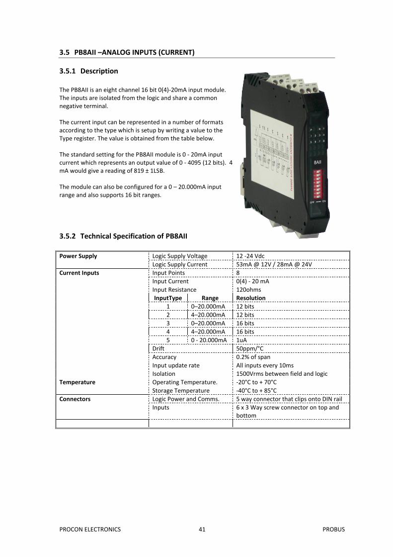
3.5 PB8AII –ANALOG INPUTS (CURRENT)
3.5.1 Description
The PB8AII is an eight channel 16 bit 0(4)-20mA input module. The inputs are isolated from the logic and share a common negative terminal. The current input can be represented in a number of formats according to the type which is setup by writing a value to the Type register. The value is obtained from the table below. The standard setting for the PB8AII module is 0 - 20mA input current which represents an output value of 0 - 4095 (12 bits). 4 mA would give a reading of 819 ± 1LSB. The module can also be configured for a 0 – 20.000mA input range and also supports 16 bit ranges.
3.5.2 Technical Specification of PB8AII
Power Supply Logic Supply Voltage 12 -24 Vdc
Logic Supply Current 53mA @ 12V / 28mA @ 24V
Current Inputs Input Points 8
Input Current 0(4) - 20 mA
Input Resistance 120ohms
InputType Range Resolution
1 0–20.000mA 12 bits
2 4–20.000mA 12 bits
3 0–20.000mA 16 bits
4 4–20.000mA 16 bits
5 0 - 20.000mA 1uA
Drift 50ppm/°C
Accuracy 0.2% of span
Input update rate All inputs every 10ms
Isolation 1500Vrms between field and logic
Temperature Operating Temperature. -20°C to + 70°C
Storage Temperature -40°C to + 85°C
Connectors Logic Power and Comms. 5 way connector that clips onto DIN rail
Inputs 6 x 3 Way screw connector on top and bottom
PROCON ELECTRONICS 42 PROBUS
3.5.3 Status Indicators
Power: Flashes to indicate the CPU is running. RS485 Rx: Flashes to indicate the unit has received a valid Modbus message. RS485 Tx: Flashes to indicate the unit has sent a Modbus message. Input Status: “ON” when the input is zero. “OFF” when the input is greater than zero and less than 20mA. “Flashing” when the input is over range, greater or equal to 20mA.
8AII
OFF ON
1 2
3 4 5
6 7
8
P R T
1 2 3 4
5 6 7 8
R = RS485 Rx
T = RS485 Tx
P = Power
Input Status 1 - 8
Switch 1
Switch 8
PROCON ELECTRONICS 43 PROBUS
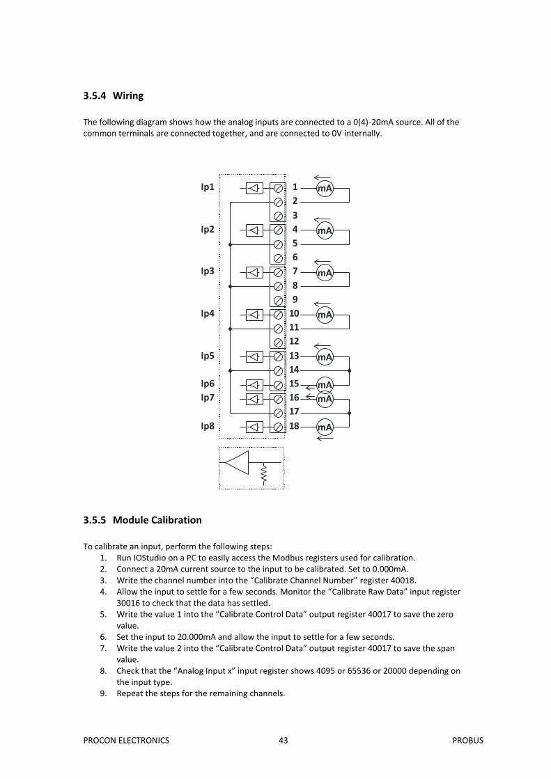
3.5.4 Wiring
The following diagram shows how the analog inputs are connected to a 0(4)-20mA source. All of the common terminals are connected together, and are connected to 0V internally.
1
2
3
4
5
6
7
8
9
10
11
12
13
14
15
16
17
18
mA
mA
mA
mA
mA
mA
mA
mA
Ip1
Ip2
Ip3
Ip4
Ip5
Ip6
Ip7
Ip8
3.5.5 Module Calibration
To calibrate an input, perform the following steps:
1. Run IOStudio on a PC to easily access the Modbus registers used for calibration. 2. Connect a 20mA current source to the input to be calibrated. Set to 0.000mA. 3. Write the channel number into the “Calibrate Channel Number” register 40018. 4. Allow the input to settle for a few seconds. Monitor the “Calibrate Raw Data” input register
30016 to check that the data has settled. 5. Write the value 1 into the “Calibrate Control Data” output register 40017 to save the zero
value. 6. Set the input to 20.000mA and allow the input to settle for a few seconds. 7. Write the value 2 into the “Calibrate Control Data” output register 40017 to save the span
value. 8. Check that the “Analog Input x” input register shows 4095 or 65536 or 20000 depending on
the input type. 9. Repeat the steps for the remaining channels.
PROCON ELECTRONICS 44 PROBUS
3.5.6 PB8AII Data Registers ( MODULE TYPE = 153)
Modbus Address
Register Name Low Limit
High Limit
Access Description
30001 S/W Version / Module Type
N/A N/A R High Byte = Software Version Low Byte = 153
30002 Analog Input 1 0 65535 R Analog Input 16 Bits
30003 Analog Input 2 0 65535 R "
30004 Analog Input 3 0 65535 R "
30005 Analog Input 4 0 65535 R "
30006 Analog Input 5 0 65535 R "
30007 Analog Input 6 0 65535 R "
30008 Analog Input 7 0 65535 R "
30009 Analog Input 8 0 65535 R "
30010 Input Status 0 65535 R bit2 = 0(open circuit or < 2), bit2 = 1(over range) bit1 = 0(OK),bit1 = 1(input < 2mA)
30016 Calibrate Raw Data
0 65535 R Raw data used to verify that the data has settled during calibration.
40017 Calibrate Control 0 2 R/W Used to step through the calibration sequence.
40018 Calibrate Channel 1 8 R/W Enter the channel number to be calibrated.
30100 DIP Switch 0 65535 R Status of DIP Switch on Front Panel
40101 Input 1 Type 1 5 R/W See specification table.
40102 Input 2 Type 1 5 R/W See specification table.
40103 Input 3 Type 1 5 R/W See specification table.
40104 Input 4 Type 1 5 R/W See specification table.
40105 Input 5 Type 1 5 R/W See specification table.
40106 Input 6 Type 1 5 R/W See specification table.
40107 Input 7 Type 1 5 R/W See specification table.
40108 Input 8 Type 1 5 R/W See specification table.
There are two status bits associated with each analog input. These bits are used to indicate if the input is zero or open circuit , in the working range 0-65535, or over range. If the input is open circuit or over range, then the error bit will be set. When the error bit is set, the range bit is zero if the input is open circuit and set if the input is over range, ie: Bit 1- Error Bit 2-Range Condition Status LED 0 don’t care Input working OK. (LED OFF) 1 0 Input Open circuit (<3mA) or zero (LED ON) 1 1 Input Over range. (LED FLASH) The analog input status can be read in a single register as follows:
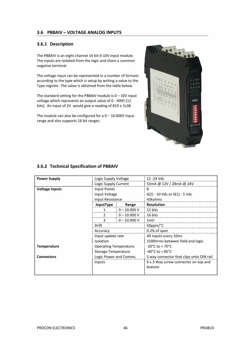
The PB8AIV is an eight channel 16 bit 0-10V input module. The inputs are isolated from the logic and share a common negative terminal. The voltage input can be represented in a number of formats according to the type which is setup by writing a value to the Type register. The value is obtained from the table below. The standard setting for the PB8AIV module is 0 – 10V input voltage which represents an output value of 0 - 4095 (12 bits). An input of 2V would give a reading of 819 ± 1LSB. The module can also be configured for a 0 – 10.000V input range and also supports 16 bit ranges.
3.6.2 Technical Specification of PB8AIV
Power Supply Logic Supply Voltage 12 -24 Vdc
Logic Supply Current 53mA @ 12V / 28mA @ 24V
Voltage Inputs Input Points 8
Input Voltage 0(2) - 10 Vdc or 0(1) - 5 Vdc
Input Resistance 43kohms
InputType Range Resolution
1 0 – 10.000 V 12 bits
2 0 – 10.000 V 16 bits
3 0 – 10.000 V 1mV
Drift 50ppm/°C
Accuracy 0.2% of span
Input update rate All inputs every 10ms
Isolation 1500Vrms between field and logic
Temperature Operating Temperature. -20°C to + 70°C
Storage Temperature -40°C to + 85°C
Connectors Logic Power and Comms. 5 way connector that clips onto DIN rail
Inputs 6 x 3 Way screw connector on top and bottom
PROCON ELECTRONICS 47 PROBUS
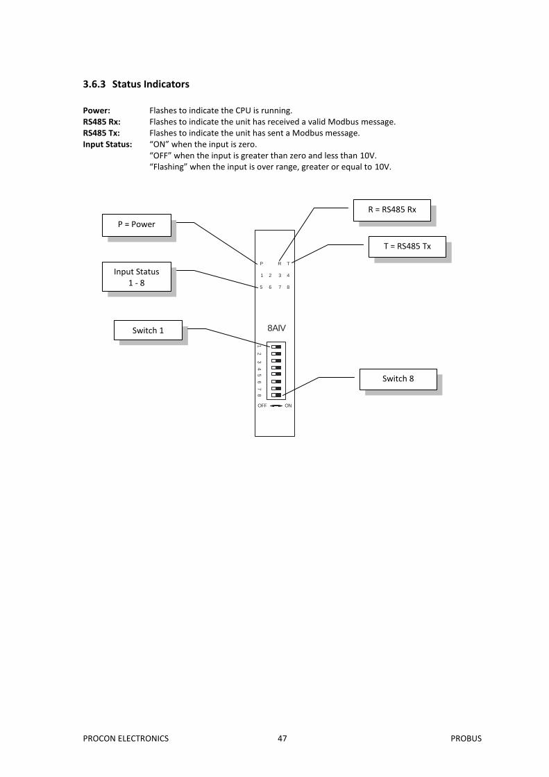
3.6.3 Status Indicators
Power: Flashes to indicate the CPU is running. RS485 Rx: Flashes to indicate the unit has received a valid Modbus message. RS485 Tx: Flashes to indicate the unit has sent a Modbus message. Input Status: “ON” when the input is zero. “OFF” when the input is greater than zero and less than 10V. “Flashing” when the input is over range, greater or equal to 10V.
8AIV
OFF ON
1 2
3 4 5
6 7
8
P R T
1 2 3 4
5 6 7 8
R = RS485 Rx
T = RS485 Tx
P = Power
Input Status 1 - 8
Switch 1
Switch 8
PROCON ELECTRONICS 48 PROBUS
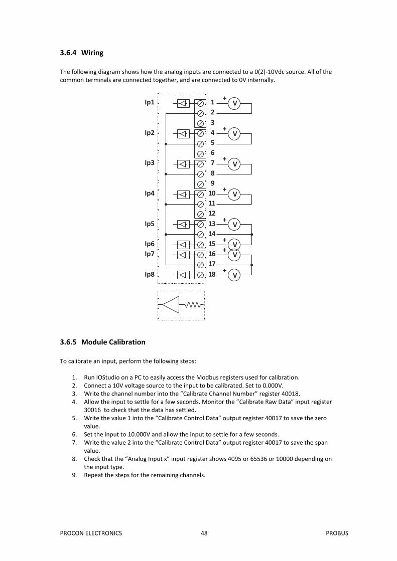
3.6.4 Wiring
The following diagram shows how the analog inputs are connected to a 0(2)-10Vdc source. All of the common terminals are connected together, and are connected to 0V internally.
1
2
3
4
5
6
7
8
9
10
11
12
13
14
15
16
17
18
V+
V+
V+
V+
V+
V+
V+
V+
Ip1
Ip2
Ip3
Ip4
Ip5
Ip6
Ip7
Ip8
3.6.5 Module Calibration
To calibrate an input, perform the following steps:
1. Run IOStudio on a PC to easily access the Modbus registers used for calibration. 2. Connect a 10V voltage source to the input to be calibrated. Set to 0.000V. 3. Write the channel number into the “Calibrate Channel Number” register 40018. 4. Allow the input to settle for a few seconds. Monitor the “Calibrate Raw Data” input register
30016 to check that the data has settled. 5. Write the value 1 into the “Calibrate Control Data” output register 40017 to save the zero
value. 6. Set the input to 10.000V and allow the input to settle for a few seconds. 7. Write the value 2 into the “Calibrate Control Data” output register 40017 to save the span
value. 8. Check that the “Analog Input x” input register shows 4095 or 65536 or 10000 depending on
the input type. 9. Repeat the steps for the remaining channels.
PROCON ELECTRONICS 49 PROBUS
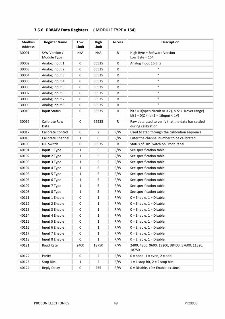
3.6.6 PB8AIV Data Registers ( MODULE TYPE = 154)
Modbus Address
Register Name Low Limit
High Limit
Access Description
30001 S/W Version / Module Type
N/A N/A R High Byte = Software Version Low Byte = 154
30002 Analog Input 1 0 65535 R Analog Input 16 Bits
30003 Analog Input 2 0 65535 R "
30004 Analog Input 3 0 65535 R "
30005 Analog Input 4 0 65535 R "
30006 Analog Input 5 0 65535 R "
30007 Analog Input 6 0 65535 R "
30008 Analog Input 7 0 65535 R "
30009 Analog Input 8 0 65535 R "
30010 Input Status 0 65535 R bit2 = 0(open circuit or < 2), bit2 = 1(over range) bit1 = 0(OK),bit1 = 1(input < 1V)
30016 Calibrate Raw Data
0 65535 R Raw data used to verify that the data has settled during calibration.
40017 Calibrate Control 0 2 R/W Used to step through the calibration sequence.
40018 Calibrate Channel 1 8 R/W Enter the channel number to be calibrated.
30100 DIP Switch 0 65535 R Status of DIP Switch on Front Panel
40101 Input 1 Type 1 5 R/W See specification table.
40102 Input 2 Type 1 5 R/W See specification table.
40103 Input 3 Type 1 5 R/W See specification table.
40104 Input 4 Type 1 5 R/W See specification table.
40105 Input 5 Type 1 5 R/W See specification table.
40106 Input 6 Type 1 5 R/W See specification table.
40107 Input 7 Type 1 5 R/W See specification table.
40108 Input 8 Type 1 5 R/W See specification table.
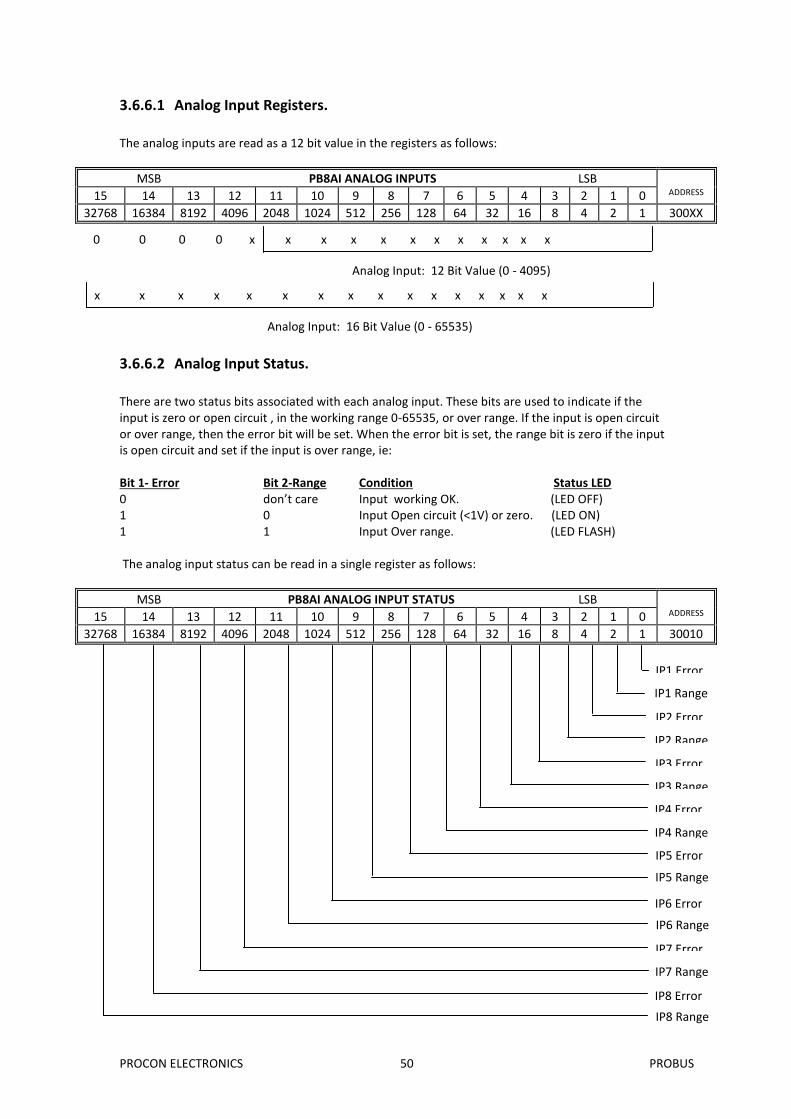
There are two status bits associated with each analog input. These bits are used to indicate if the input is zero or open circuit , in the working range 0-65535, or over range. If the input is open circuit or over range, then the error bit will be set. When the error bit is set, the range bit is zero if the input is open circuit and set if the input is over range, ie: Bit 1- Error Bit 2-Range Condition Status LED 0 don’t care Input working OK. (LED OFF) 1 0 Input Open circuit (<1V) or zero. (LED ON) 1 1 Input Over range. (LED FLASH) The analog input status can be read in a single register as follows:
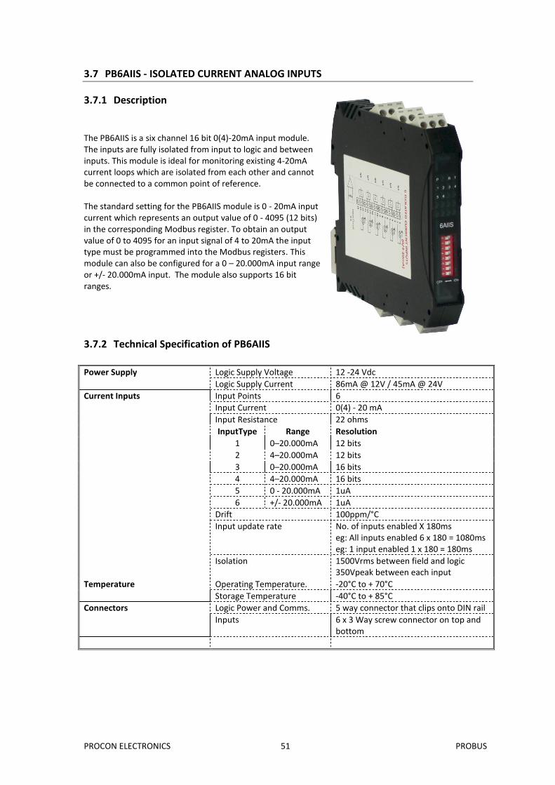
The PB6AIIS is a six channel 16 bit 0(4)-20mA input module. The inputs are fully isolated from input to logic and between inputs. This module is ideal for monitoring existing 4-20mA current loops which are isolated from each other and cannot be connected to a common point of reference. The standard setting for the PB6AIIS module is 0 - 20mA input current which represents an output value of 0 - 4095 (12 bits) in the corresponding Modbus register. To obtain an output value of 0 to 4095 for an input signal of 4 to 20mA the input type must be programmed into the Modbus registers. This module can also be configured for a 0 – 20.000mA input range or +/- 20.000mA input. The module also supports 16 bit ranges.
3.7.2 Technical Specification of PB6AIIS
Power Supply Logic Supply Voltage 12 -24 Vdc
Logic Supply Current 86mA @ 12V / 45mA @ 24V
Current Inputs Input Points 6
Input Current 0(4) - 20 mA
Input Resistance 22 ohms
InputType Range Resolution
1 0–20.000mA 12 bits
2 4–20.000mA 12 bits
3 0–20.000mA 16 bits
4 4–20.000mA 16 bits
5 0 - 20.000mA 1uA
6 +/- 20.000mA 1uA
Drift 100ppm/°C
Input update rate No. of inputs enabled X 180ms eg: All inputs enabled 6 x 180 = 1080ms eg: 1 input enabled 1 x 180 = 180ms
Isolation 1500Vrms between field and logic 350Vpeak between each input
Temperature Operating Temperature. -20°C to + 70°C
Storage Temperature -40°C to + 85°C
Connectors Logic Power and Comms. 5 way connector that clips onto DIN rail
Inputs 6 x 3 Way screw connector on top and bottom
PROCON ELECTRONICS 52 PROBUS
3.7.3 Status Indicators
Power: Flashes to indicate the CPU is running. RS485 Rx: Flashes to indicate the unit has received a valid Modbus message. RS485 Tx: Flashes to indicate the unit has sent a Modbus message. Input Status: “ON” when the input is zero. “OFF” when the input is greater than zero and less than 20mA. “Flashing” when the input is over range, greater or equal to 20mA.
6AIIS
OFF ON
1 2
3 4 5
6 7
8
P R T
1 2 3 4
5 6
R = RS485 Rx
T = RS485 Tx
P = Power
Input Status 1 - 6
Switch 1
Switch 8
PROCON ELECTRONICS 53 PROBUS
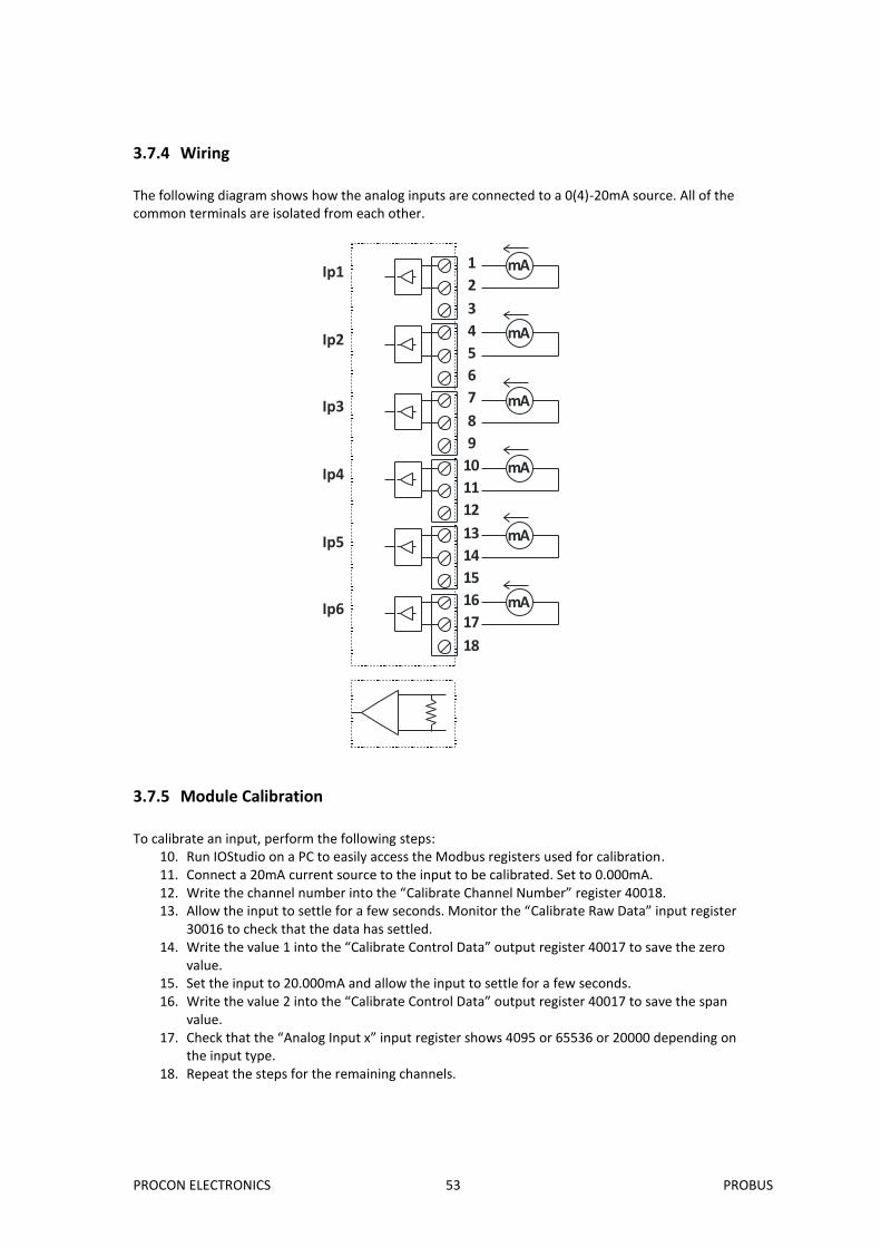
3.7.4 Wiring
The following diagram shows how the analog inputs are connected to a 0(4)-20mA source. All of the common terminals are isolated from each other.
1
2
3
4
5
6
7
8
9
10
11
12
13
14
15
16
17
18
Ip1
Ip2
Ip3
Ip4
Ip5
Ip6
mA
mA
mA
mA
mA
mA
3.7.5 Module Calibration
To calibrate an input, perform the following steps:
10. Run IOStudio on a PC to easily access the Modbus registers used for calibration. 11. Connect a 20mA current source to the input to be calibrated. Set to 0.000mA. 12. Write the channel number into the “Calibrate Channel Number” register 40018. 13. Allow the input to settle for a few seconds. Monitor the “Calibrate Raw Data” input register
30016 to check that the data has settled. 14. Write the value 1 into the “Calibrate Control Data” output register 40017 to save the zero
value. 15. Set the input to 20.000mA and allow the input to settle for a few seconds. 16. Write the value 2 into the “Calibrate Control Data” output register 40017 to save the span
value. 17. Check that the “Analog Input x” input register shows 4095 or 65536 or 20000 depending on
the input type. 18. Repeat the steps for the remaining channels.
PROCON ELECTRONICS 54 PROBUS
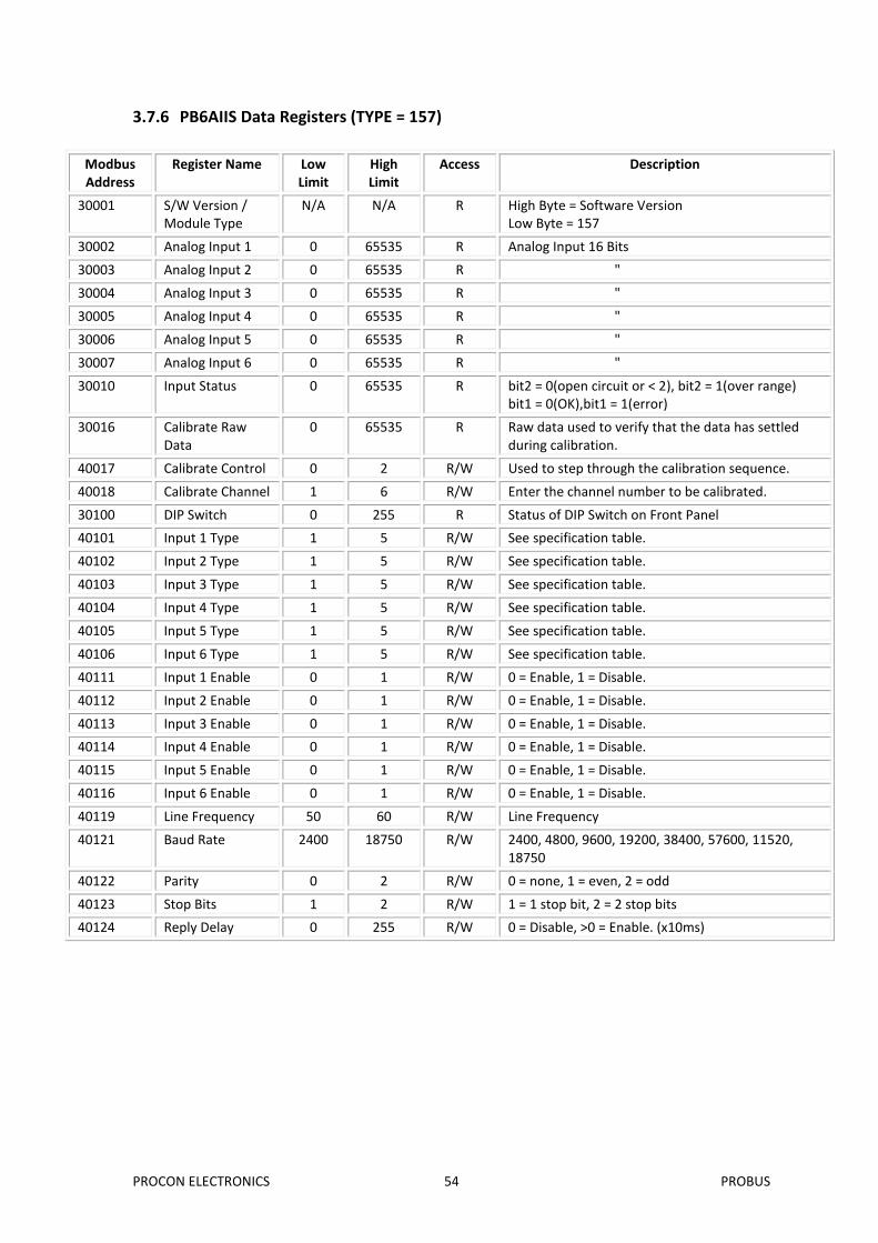
3.7.6 PB6AIIS Data Registers (TYPE = 157)
Modbus Address
Register Name Low Limit
High Limit
Access Description
30001 S/W Version / Module Type
N/A N/A R High Byte = Software Version Low Byte = 157
30002 Analog Input 1 0 65535 R Analog Input 16 Bits
30003 Analog Input 2 0 65535 R "
30004 Analog Input 3 0 65535 R "
30005 Analog Input 4 0 65535 R "
30006 Analog Input 5 0 65535 R "
30007 Analog Input 6 0 65535 R "
30010 Input Status 0 65535 R bit2 = 0(open circuit or < 2), bit2 = 1(over range) bit1 = 0(OK),bit1 = 1(error)
30016 Calibrate Raw Data
0 65535 R Raw data used to verify that the data has settled during calibration.
40017 Calibrate Control 0 2 R/W Used to step through the calibration sequence.
40018 Calibrate Channel 1 6 R/W Enter the channel number to be calibrated.
30100 DIP Switch 0 255 R Status of DIP Switch on Front Panel
40101 Input 1 Type 1 5 R/W See specification table.
40102 Input 2 Type 1 5 R/W See specification table.
40103 Input 3 Type 1 5 R/W See specification table.
40104 Input 4 Type 1 5 R/W See specification table.
40105 Input 5 Type 1 5 R/W See specification table.
40106 Input 6 Type 1 5 R/W See specification table.
There are two status bits associated with each analog input. These bits are used to indicate if the input is zero or open circuit , in the working range 0-4095, or over range. If the input is open circuit or over range, then the error bit will be set. When the error bit is set, the range bit is zero if the input is open circuit and set if the input is over range, ie: Bit 1- Error Bit 2-Range Condition Status LED 0 don’t care Input working OK. (LED OFF) 1 0 Input Open circuit (<3mA) or zero (LED ON) 1 1 Input Over range. (LED FLASH) The analog input status can be read in a single register as follows:
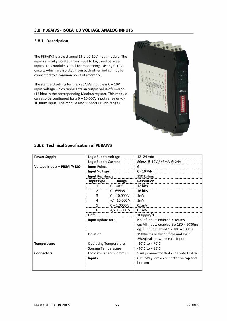
The PB6AIVS is a six channel 16 bit 0-10V input module. The inputs are fully isolated from input to logic and between inputs. This module is ideal for monitoring existing 0-10V circuits which are isolated from each other and cannot be connected to a common point of reference. The standard setting for the PB6AIVS module is 0 – 10V input voltage which represents an output value of 0 - 4095 (12 bits) in the corresponding Modbus register. This module can also be configured for a 0 – 10.000V input range or +/- 10.000V input. The module also supports 16 bit ranges.
3.8.2 Technical Specification of PB8AIVS
Power Supply Logic Supply Voltage 12 -24 Vdc
Logic Supply Current 86mA @ 12V / 45mA @ 24V
Voltage Inputs – PB8AI/V ISO Input Points 6
Input Voltage 0 - 10 Vdc
Input Resistance 110 Kohms
InputType Range Resolution
1 0 – 4095 12 bits
2 0 - 65535 16 bits
3 0 – 10.000 V 1mV
4 +/- 10.000 V 1mV
5 0 – 1.0000 V 0.1mV
6 +/- 1.0000 V 0.1mV
Drift 100ppm/°C
Input update rate No. of inputs enabled X 180ms eg: All inputs enabled 6 x 180 = 1080ms eg: 1 input enabled 1 x 180 = 180ms
Isolation 1500Vrms between field and logic 350Vpeak between each input
Temperature Operating Temperature. -20°C to + 70°C
Storage Temperature -40°C to + 85°C
Connectors Logic Power and Comms. 5 way connector that clips onto DIN rail
Inputs 6 x 3 Way screw connector on top and bottom
PROCON ELECTRONICS 57 PROBUS
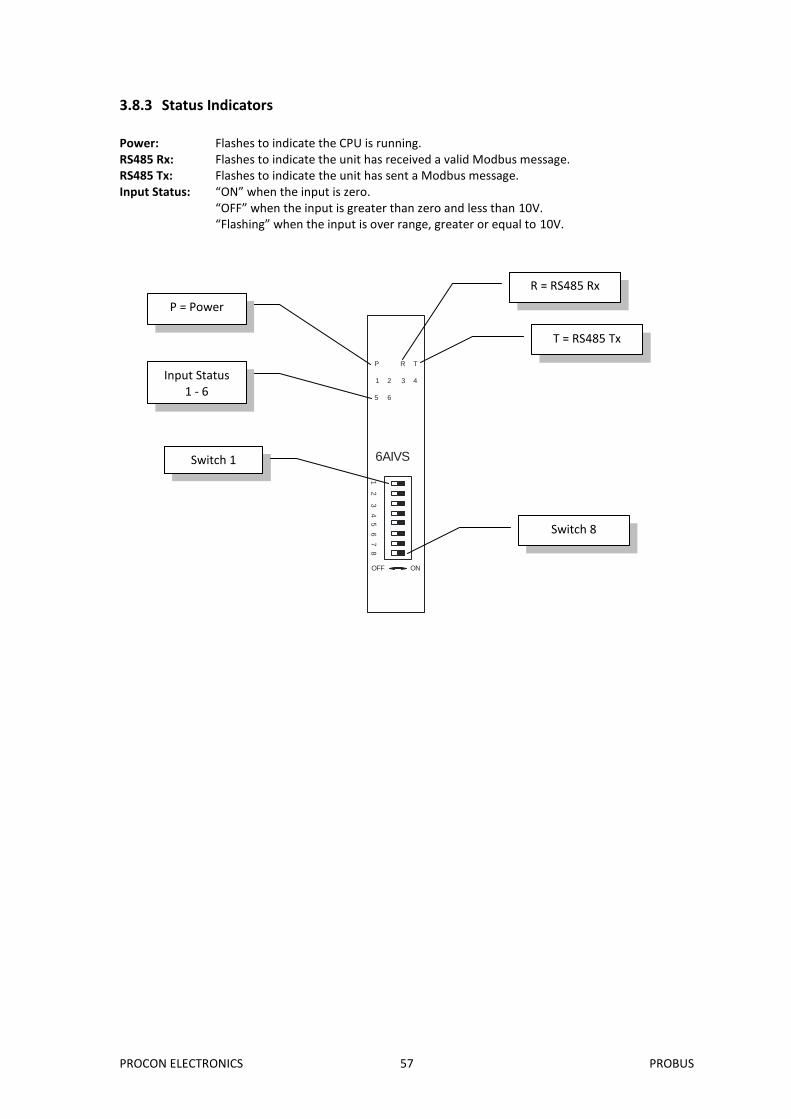
3.8.3 Status Indicators
Power: Flashes to indicate the CPU is running. RS485 Rx: Flashes to indicate the unit has received a valid Modbus message. RS485 Tx: Flashes to indicate the unit has sent a Modbus message. Input Status: “ON” when the input is zero. “OFF” when the input is greater than zero and less than 10V. “Flashing” when the input is over range, greater or equal to 10V.
6AIVS
OFF ON
1 2
3 4 5
6 7
8
P R T
1 2 3 4
5 6
R = RS485 Rx
T = RS485 Tx
P = Power
Input Status 1 - 6
Switch 1
Switch 8
PROCON ELECTRONICS 58 PROBUS
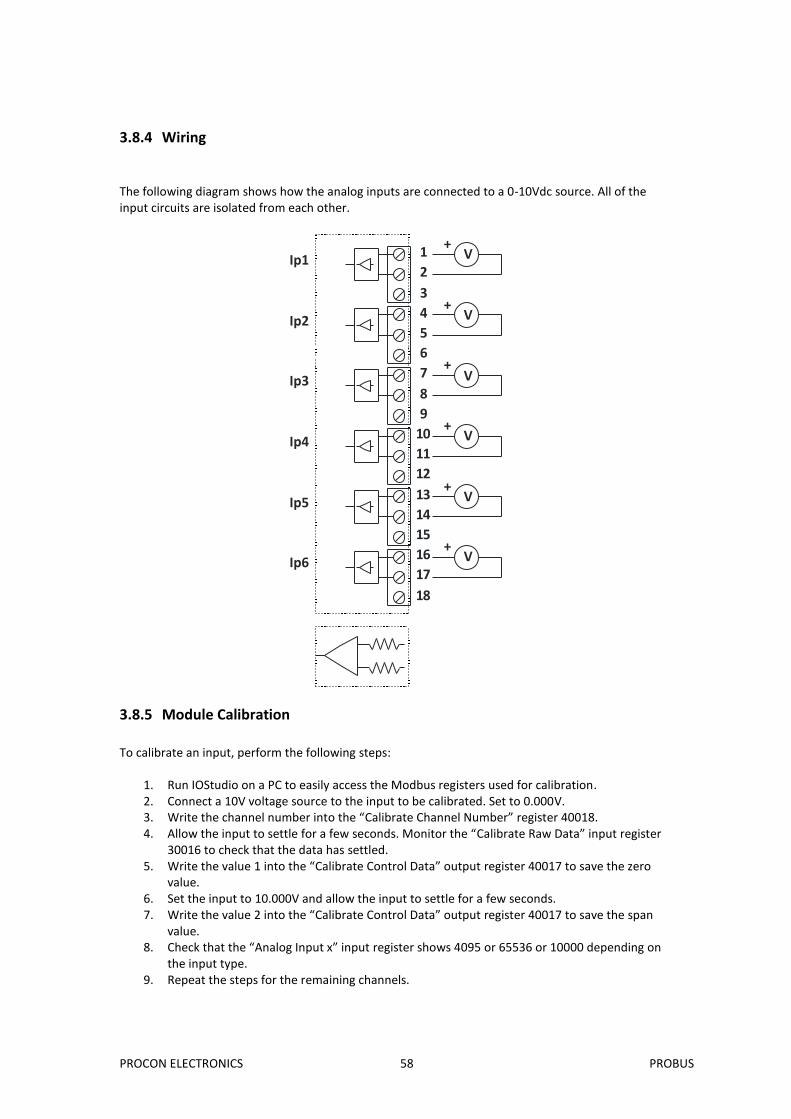
3.8.4 Wiring
The following diagram shows how the analog inputs are connected to a 0-10Vdc source. All of the input circuits are isolated from each other.
1
2
3
4
5
6
7
8
9
10
11
12
13
14
15
16
17
18
V+
V+
V+
V+
V+
V+
Ip1
Ip2
Ip3
Ip4
Ip5
Ip6
3.8.5 Module Calibration
To calibrate an input, perform the following steps:
1. Run IOStudio on a PC to easily access the Modbus registers used for calibration. 2. Connect a 10V voltage source to the input to be calibrated. Set to 0.000V. 3. Write the channel number into the “Calibrate Channel Number” register 40018. 4. Allow the input to settle for a few seconds. Monitor the “Calibrate Raw Data” input register
30016 to check that the data has settled. 5. Write the value 1 into the “Calibrate Control Data” output register 40017 to save the zero
value. 6. Set the input to 10.000V and allow the input to settle for a few seconds. 7. Write the value 2 into the “Calibrate Control Data” output register 40017 to save the span
value. 8. Check that the “Analog Input x” input register shows 4095 or 65536 or 10000 depending on
the input type. 9. Repeat the steps for the remaining channels.
PROCON ELECTRONICS 59 PROBUS
3.8.6 PB6AIVSData Registers (TYPE = 158)
Modbus Address
Register Name Low Limit
High Limit
Access Description
30001 S/W Version / Module Type
N/A N/A R High Byte = Software Version Low Byte = 158
30002 Analog Input 1 0 65535 R Analog Input 16 Bits
30003 Analog Input 2 0 65535 R "
30004 Analog Input 3 0 65535 R "
30005 Analog Input 4 0 65535 R "
30006 Analog Input 5 0 65535 R "
30007 Analog Input 6 0 65535 R "
30010 Input Status 0 65535 R bit2 = 0(open circuit or < 2), bit2 = 1(over range) bit1 = 0(OK),bit1 = 1(error)
30016 Calibrate Raw Data
0 65535 R Raw data used to verify that the data has settled during calibration.
40017 Calibrate Control 0 2 R/W Used to step through the calibration sequence.
40018 Calibrate Channel 1 6 R/W Enter the channel number to be calibrated.
30100 DIP Switch 0 255 R Status of DIP Switch on Front Panel
40101 Input 1 Type 1 5 R/W See specification table.
40102 Input 2 Type 1 5 R/W See specification table.
40103 Input 3 Type 1 5 R/W See specification table.
40104 Input 4 Type 1 5 R/W See specification table.
40105 Input 5 Type 1 5 R/W See specification table.
40106 Input 6 Type 1 5 R/W See specification table.
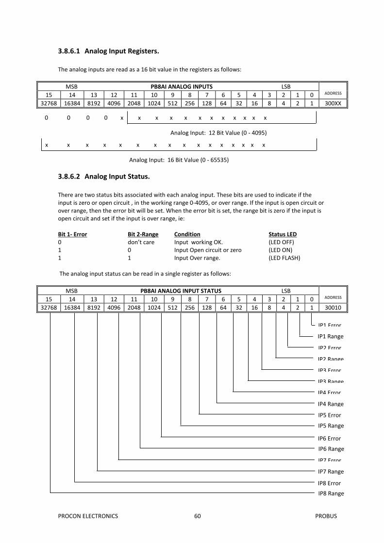
There are two status bits associated with each analog input. These bits are used to indicate if the input is zero or open circuit , in the working range 0-4095, or over range. If the input is open circuit or over range, then the error bit will be set. When the error bit is set, the range bit is zero if the input is open circuit and set if the input is over range, ie: Bit 1- Error Bit 2-Range Condition Status LED 0 don’t care Input working OK. (LED OFF) 1 0 Input Open circuit or zero (LED ON) 1 1 Input Over range. (LED FLASH) The analog input status can be read in a single register as follows:
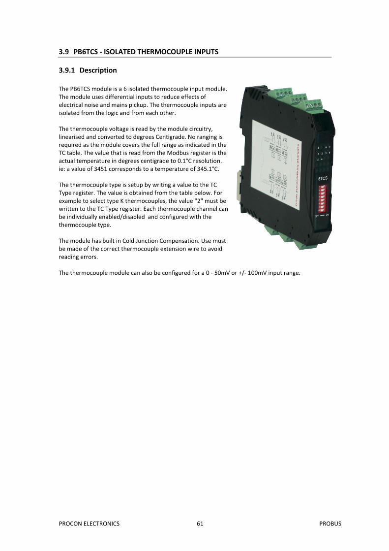
The PB6TCS module is a 6 isolated thermocouple input module. The module uses differential inputs to reduce effects of electrical noise and mains pickup. The thermocouple inputs are isolated from the logic and from each other. The thermocouple voltage is read by the module circuitry, linearised and converted to degrees Centigrade. No ranging is required as the module covers the full range as indicated in the TC table. The value that is read from the Modbus register is the actual temperature in degrees centigrade to 0.1°C resolution. ie: a value of 3451 corresponds to a temperature of 345.1°C. The thermocouple type is setup by writing a value to the TC Type register. The value is obtained from the table below. For example to select type K thermocouples, the value "2" must be written to the TC Type register. Each thermocouple channel can be individually enabled/disabled and configured with the thermocouple type. The module has built in Cold Junction Compensation. Use must be made of the correct thermocouple extension wire to avoid reading errors. The thermocouple module can also be configured for a 0 - 50mV or +/- 100mV input range.
PROCON ELECTRONICS 62 PROBUS
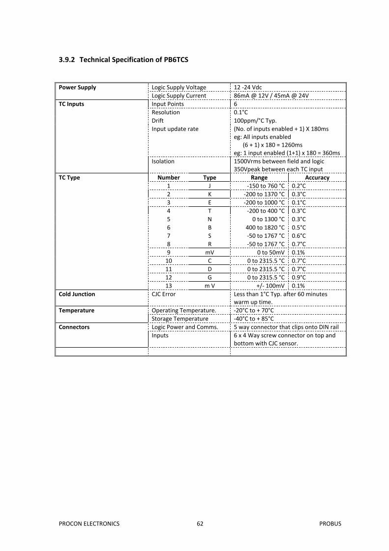
3.9.2 Technical Specification of PB6TCS
Power Supply Logic Supply Voltage 12 -24 Vdc
Logic Supply Current 86mA @ 12V / 45mA @ 24V
TC Inputs Input Points 6
Resolution 0.1°C
Drift 100ppm/°C Typ.
Input update rate (No. of inputs enabled + 1) X 180ms eg: All inputs enabled (6 + 1) x 180 = 1260ms eg: 1 input enabled (1+1) x 180 = 360ms
Isolation 1500Vrms between field and logic 350Vpeak between each TC input
TC Type Number Type Range Accuracy
1 J -150 to 760 °C 0.2°C
2 K -200 to 1370 °C 0.3°C
3 E -200 to 1000 °C 0.1°C
4 T -200 to 400 °C 0.3°C
5 N 0 to 1300 °C 0.3°C
6 B 400 to 1820 °C 0.5°C
7 S -50 to 1767 °C 0.6°C
8 R -50 to 1767 °C 0.7°C
9 mV 0 to 50mV 0.1%
10 C 0 to 2315.5 °C 0.7°C
11 D 0 to 2315.5 °C 0.7°C
12 G 0 to 2315.5 °C 0.9°C
13 m V +/- 100mV 0.1%
Cold Junction CJC Error Less than 1°C Typ. after 60 minutes warm up time.
Temperature Operating Temperature. -20°C to + 70°C
Storage Temperature -40°C to + 85°C
Connectors Logic Power and Comms. 5 way connector that clips onto DIN rail
Inputs 6 x 4 Way screw connector on top and bottom with CJC sensor.
PROCON ELECTRONICS 63 PROBUS
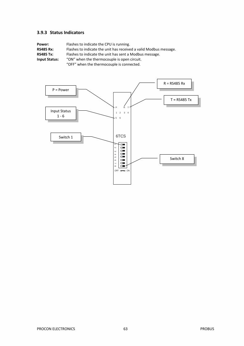
3.9.3 Status Indicators
Power: Flashes to indicate the CPU is running. RS485 Rx: Flashes to indicate the unit has received a valid Modbus message. RS485 Tx: Flashes to indicate the unit has sent a Modbus message. Input Status: “ON” when the thermocouple is open circuit. “OFF” when the thermocouple is connected.
6TCS
OFF ON
1 2
3 4 5
6 7
8
P R T
1 2 3 4
5 6
R = RS485 Rx
T = RS485 Tx
P = Power
Input Status 1 - 6
Switch 1
Switch 8
PROCON ELECTRONICS 64 PROBUS
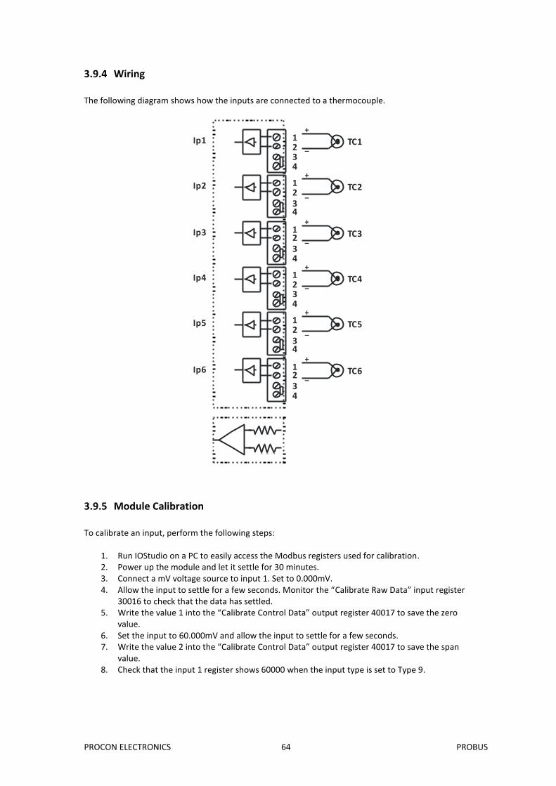
3.9.4 Wiring
The following diagram shows how the inputs are connected to a thermocouple.
3.9.5 Module Calibration
To calibrate an input, perform the following steps:
1. Run IOStudio on a PC to easily access the Modbus registers used for calibration. 2. Power up the module and let it settle for 30 minutes. 3. Connect a mV voltage source to input 1. Set to 0.000mV. 4. Allow the input to settle for a few seconds. Monitor the “Calibrate Raw Data” input register
30016 to check that the data has settled. 5. Write the value 1 into the “Calibrate Control Data” output register 40017 to save the zero
value. 6. Set the input to 60.000mV and allow the input to settle for a few seconds. 7. Write the value 2 into the “Calibrate Control Data” output register 40017 to save the span
value. 8. Check that the input 1 register shows 60000 when the input type is set to Type 9.
Ip1
Ip2
Ip3
Ip4
Ip5
Ip6
123
TC1
+
_
4
123
TC2
+
_
4
123
TC3
+
_
4
123
TC4
+
_
4
123
TC5
+
_
4
123
TC6
+
_
4
PROCON ELECTRONICS 65 PROBUS
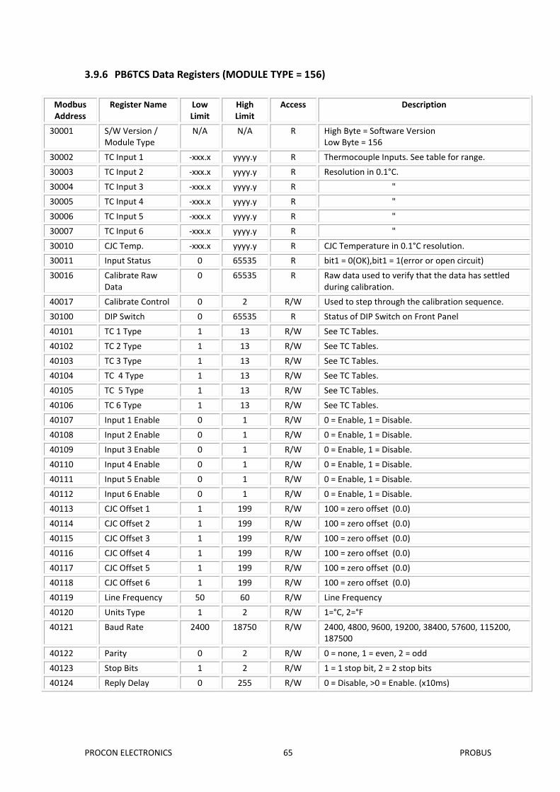
3.9.6 PB6TCS Data Registers (MODULE TYPE = 156)
Modbus Address
Register Name Low Limit
High Limit
Access Description
30001 S/W Version / Module Type
N/A N/A R High Byte = Software Version Low Byte = 156
30002 TC Input 1 -xxx.x yyyy.y R Thermocouple Inputs. See table for range.
30003 TC Input 2 -xxx.x yyyy.y R Resolution in 0.1°C.
30004 TC Input 3 -xxx.x yyyy.y R "
30005 TC Input 4 -xxx.x yyyy.y R "
30006 TC Input 5 -xxx.x yyyy.y R "
30007 TC Input 6 -xxx.x yyyy.y R "
30010 CJC Temp. -xxx.x yyyy.y R CJC Temperature in 0.1°C resolution.
30011 Input Status 0 65535 R bit1 = 0(OK),bit1 = 1(error or open circuit)
30016 Calibrate Raw Data
0 65535 R Raw data used to verify that the data has settled during calibration.
40017 Calibrate Control 0 2 R/W Used to step through the calibration sequence.
30100 DIP Switch 0 65535 R Status of DIP Switch on Front Panel
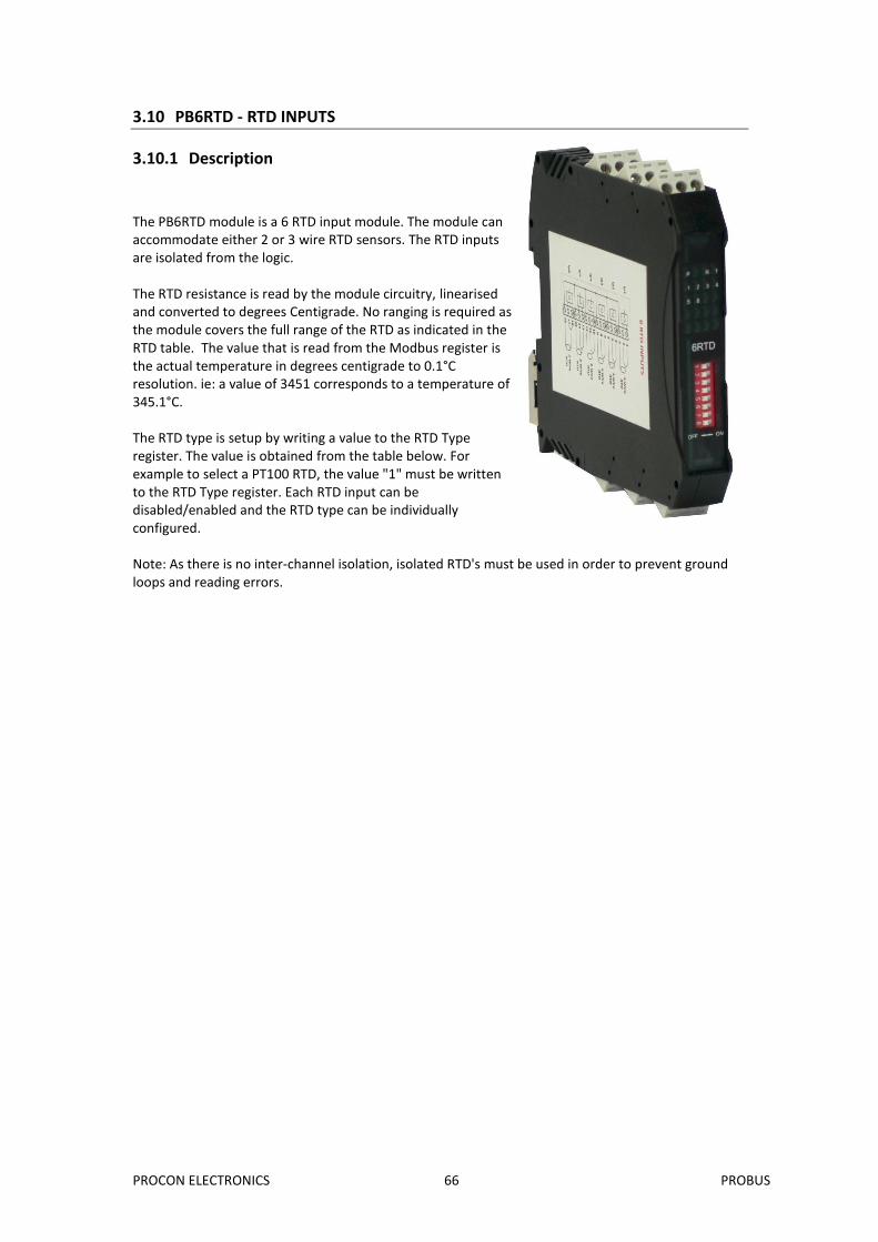
The PB6RTD module is a 6 RTD input module. The module can accommodate either 2 or 3 wire RTD sensors. The RTD inputs are isolated from the logic. The RTD resistance is read by the module circuitry, linearised and converted to degrees Centigrade. No ranging is required as the module covers the full range of the RTD as indicated in the RTD table. The value that is read from the Modbus register is the actual temperature in degrees centigrade to 0.1°C resolution. ie: a value of 3451 corresponds to a temperature of 345.1°C. The RTD type is setup by writing a value to the RTD Type register. The value is obtained from the table below. For example to select a PT100 RTD, the value "1" must be written to the RTD Type register. Each RTD input can be disabled/enabled and the RTD type can be individually configured. Note: As there is no inter-channel isolation, isolated RTD's must be used in order to prevent ground loops and reading errors.
PROCON ELECTRONICS 67 PROBUS
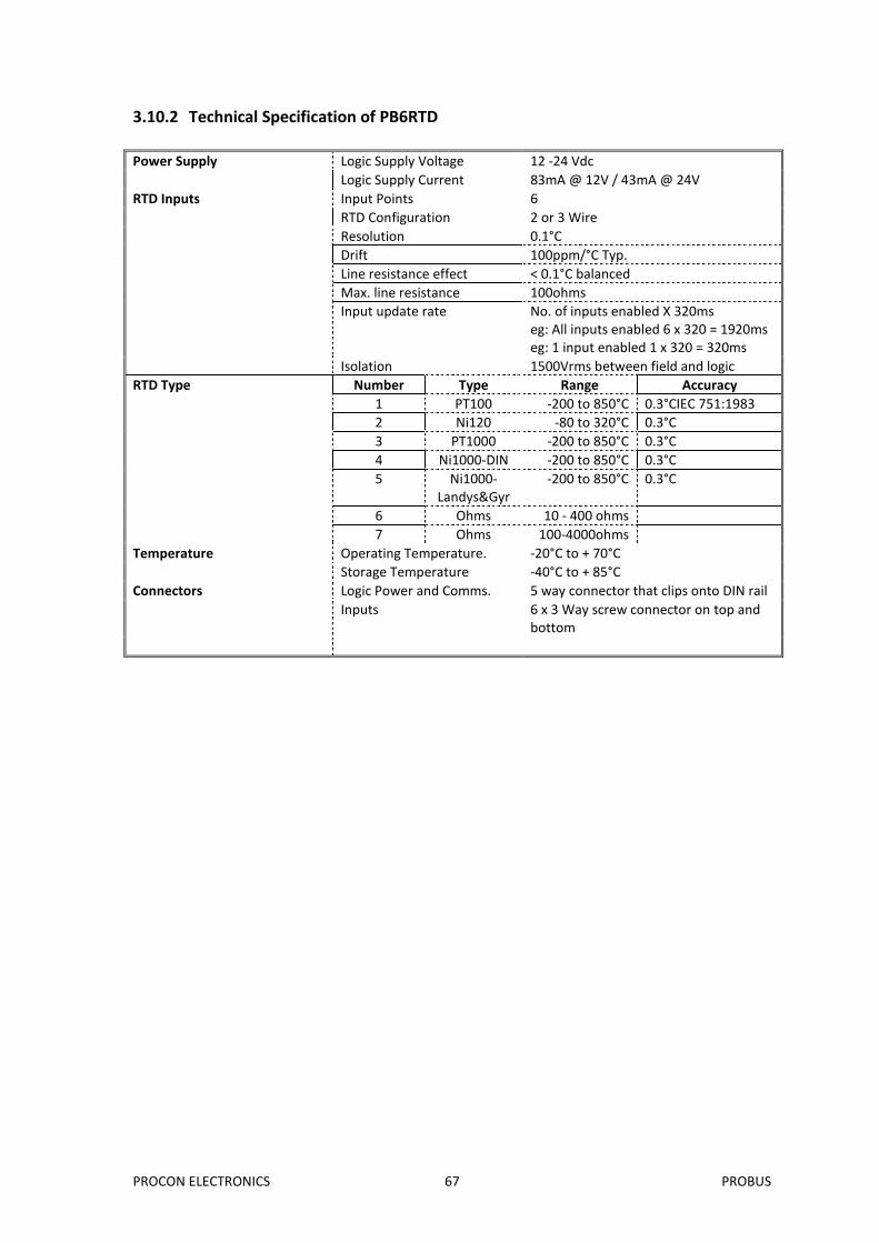
3.10.2 Technical Specification of PB6RTD
Power Supply Logic Supply Voltage 12 -24 Vdc
Logic Supply Current 83mA @ 12V / 43mA @ 24V
RTD Inputs Input Points 6
RTD Configuration 2 or 3 Wire
Resolution 0.1°C
Drift 100ppm/°C Typ.
Line resistance effect < 0.1°C balanced
Max. line resistance 100ohms
Input update rate No. of inputs enabled X 320ms eg: All inputs enabled 6 x 320 = 1920ms eg: 1 input enabled 1 x 320 = 320ms
Isolation 1500Vrms between field and logic
RTD Type Number Type Range Accuracy
1 PT100 -200 to 850°C 0.3°CIEC 751:1983
2 Ni120 -80 to 320°C 0.3°C
3 PT1000 -200 to 850°C 0.3°C
4 Ni1000-DIN -200 to 850°C 0.3°C
5 Ni1000-Landys&Gyr
-200 to 850°C 0.3°C
6 Ohms 10 - 400 ohms
7 Ohms 100-4000ohms
Temperature Operating Temperature. -20°C to + 70°C
Storage Temperature -40°C to + 85°C
Connectors Logic Power and Comms. 5 way connector that clips onto DIN rail
Inputs 6 x 3 Way screw connector on top and bottom
PROCON ELECTRONICS 68 PROBUS
3.10.3 Status Indicators
Power: Flashes to indicate the CPU is running. RS485 Rx: Flashes to indicate the unit has received a valid Modbus message. RS485 Tx: Flashes to indicate the unit has sent a Modbus message. Input Status: “ON” when the RTD is open circuit. “OFF” when the RTD is connected.
6RTD
OFF ON
1 2
3 4 5
6 7
8
P R T
1 2 3 4
5 6
R = RS485 Rx
T = RS485 Tx
P = Power
Input Status 1 - 6
Switch 1
Switch 8
PROCON ELECTRONICS 69 PROBUS
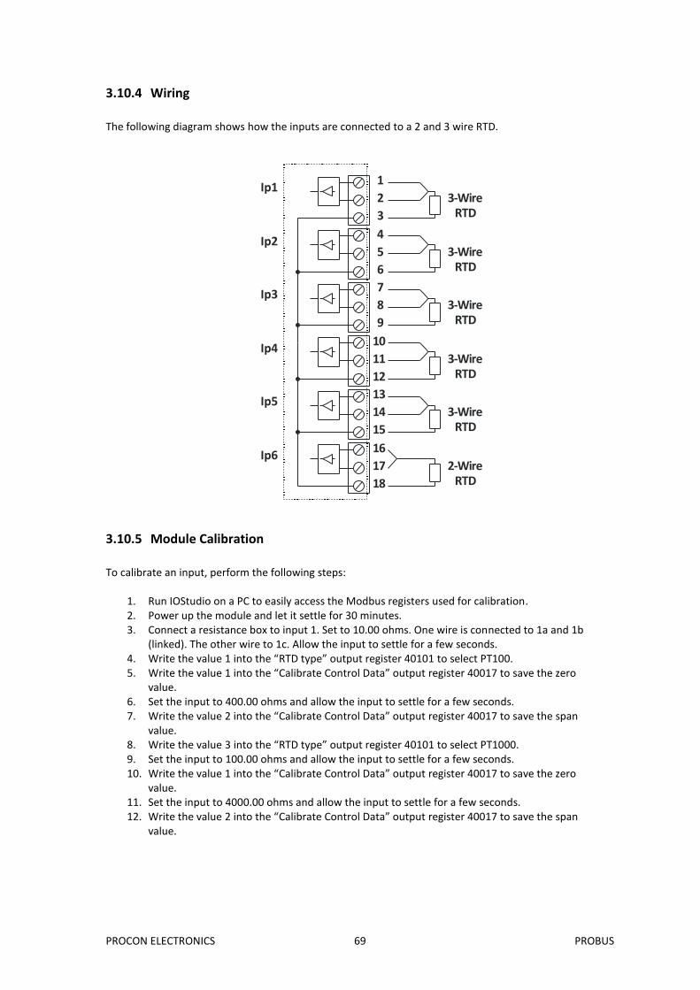
3.10.4 Wiring
The following diagram shows how the inputs are connected to a 2 and 3 wire RTD.
1
2
3
4
5
6
7
8
9
10
11
12
13
14
15
16
17
18
Ip1
Ip2
Ip3
Ip4
Ip5
Ip6
3-WireRTD
3-WireRTD
3-WireRTD
3-WireRTD
2-WireRTD
3-WireRTD
3.10.5 Module Calibration
To calibrate an input, perform the following steps:
1. Run IOStudio on a PC to easily access the Modbus registers used for calibration. 2. Power up the module and let it settle for 30 minutes. 3. Connect a resistance box to input 1. Set to 10.00 ohms. One wire is connected to 1a and 1b
(linked). The other wire to 1c. Allow the input to settle for a few seconds. 4. Write the value 1 into the “RTD type” output register 40101 to select PT100. 5. Write the value 1 into the “Calibrate Control Data” output register 40017 to save the zero
value. 6. Set the input to 400.00 ohms and allow the input to settle for a few seconds. 7. Write the value 2 into the “Calibrate Control Data” output register 40017 to save the span
value. 8. Write the value 3 into the “RTD type” output register 40101 to select PT1000. 9. Set the input to 100.00 ohms and allow the input to settle for a few seconds. 10. Write the value 1 into the “Calibrate Control Data” output register 40017 to save the zero
value. 11. Set the input to 4000.00 ohms and allow the input to settle for a few seconds. 12. Write the value 2 into the “Calibrate Control Data” output register 40017 to save the span
value.
PROCON ELECTRONICS 70 PROBUS
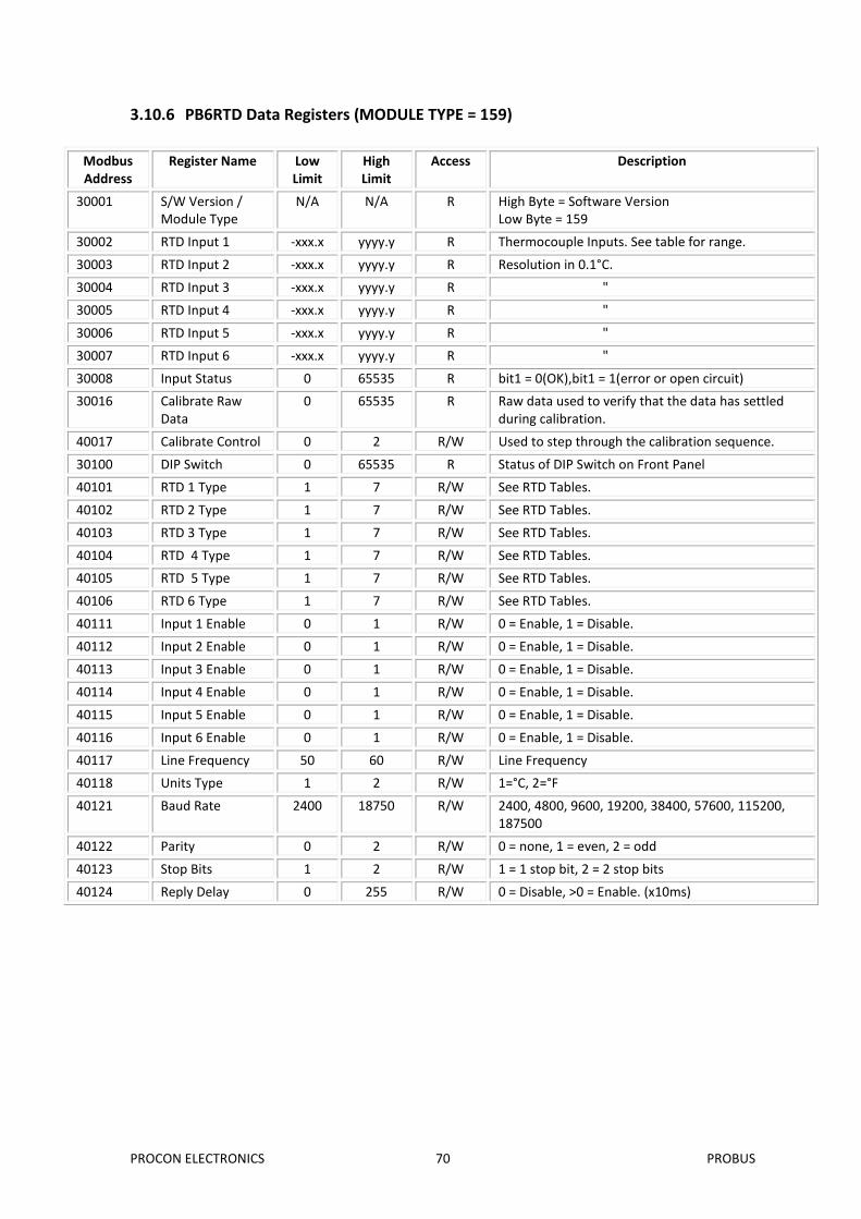
3.10.6 PB6RTD Data Registers (MODULE TYPE = 159)
Modbus Address
Register Name Low Limit
High Limit
Access Description
30001 S/W Version / Module Type
N/A N/A R High Byte = Software Version Low Byte = 159
30002 RTD Input 1 -xxx.x yyyy.y R Thermocouple Inputs. See table for range.
30003 RTD Input 2 -xxx.x yyyy.y R Resolution in 0.1°C.
30004 RTD Input 3 -xxx.x yyyy.y R "
30005 RTD Input 4 -xxx.x yyyy.y R "
30006 RTD Input 5 -xxx.x yyyy.y R "
30007 RTD Input 6 -xxx.x yyyy.y R "
30008 Input Status 0 65535 R bit1 = 0(OK),bit1 = 1(error or open circuit)
30016 Calibrate Raw Data
0 65535 R Raw data used to verify that the data has settled during calibration.
40017 Calibrate Control 0 2 R/W Used to step through the calibration sequence.
30100 DIP Switch 0 65535 R Status of DIP Switch on Front Panel
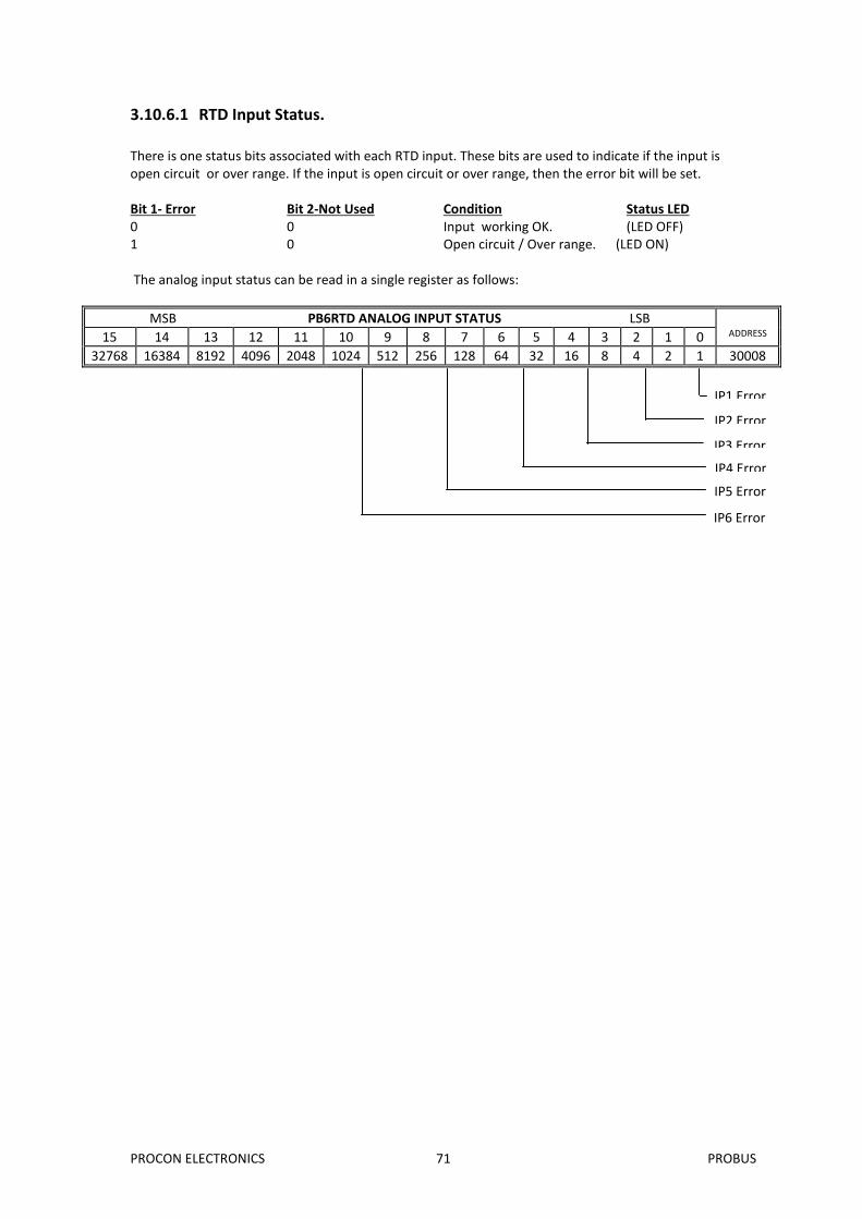
There is one status bits associated with each RTD input. These bits are used to indicate if the input is open circuit or over range. If the input is open circuit or over range, then the error bit will be set. Bit 1- Error Bit 2-Not Used Condition Status LED 0 0 Input working OK. (LED OFF) 1 0 Open circuit / Over range. (LED ON) The analog input status can be read in a single register as follows:
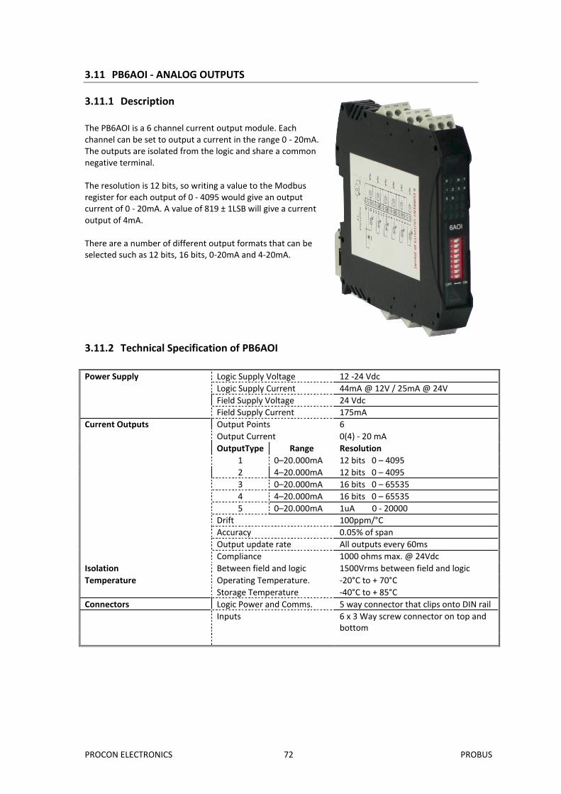
The PB6AOI is a 6 channel current output module. Each channel can be set to output a current in the range 0 - 20mA. The outputs are isolated from the logic and share a common negative terminal. The resolution is 12 bits, so writing a value to the Modbus register for each output of 0 - 4095 would give an output current of 0 - 20mA. A value of 819 ± 1LSB will give a current output of 4mA. There are a number of different output formats that can be selected such as 12 bits, 16 bits, 0-20mA and 4-20mA.
3.11.2 Technical Specification of PB6AOI
Power Supply Logic Supply Voltage 12 -24 Vdc
Logic Supply Current 44mA @ 12V / 25mA @ 24V
Field Supply Voltage 24 Vdc
Field Supply Current 175mA
Current Outputs Output Points 6
Output Current 0(4) - 20 mA
OutputType Range Resolution
1 0–20.000mA 12 bits 0 – 4095
2 4–20.000mA 12 bits 0 – 4095
3 0–20.000mA 16 bits 0 – 65535
4 4–20.000mA 16 bits 0 – 65535
5 0–20.000mA 1uA 0 - 20000
Drift 100ppm/°C
Accuracy 0.05% of span
Output update rate All outputs every 60ms
Compliance 1000 ohms max. @ 24Vdc
Isolation Between field and logic 1500Vrms between field and logic
Temperature Operating Temperature. -20°C to + 70°C
Storage Temperature -40°C to + 85°C
Connectors Logic Power and Comms. 5 way connector that clips onto DIN rail
Inputs 6 x 3 Way screw connector on top and bottom
PROCON ELECTRONICS 73 PROBUS
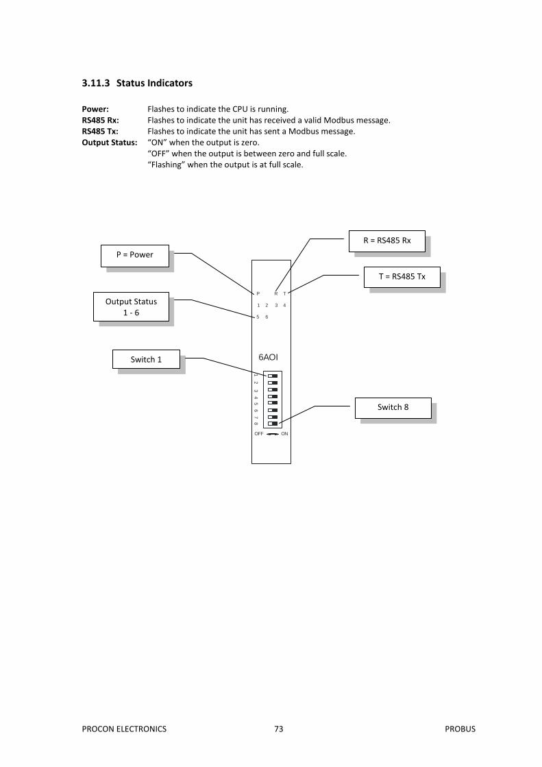
3.11.3 Status Indicators
Power: Flashes to indicate the CPU is running. RS485 Rx: Flashes to indicate the unit has received a valid Modbus message. RS485 Tx: Flashes to indicate the unit has sent a Modbus message. Output Status: “ON” when the output is zero. “OFF” when the output is between zero and full scale. “Flashing” when the output is at full scale.
6AOI
OFF ON
1 2
3 4 5
6 7
8
P R T
1 2 3 4
5 6
R = RS485 Rx
T = RS485 Tx
P = Power
Output Status 1 - 6
Switch 1
Switch 8
PROCON ELECTRONICS 74 PROBUS
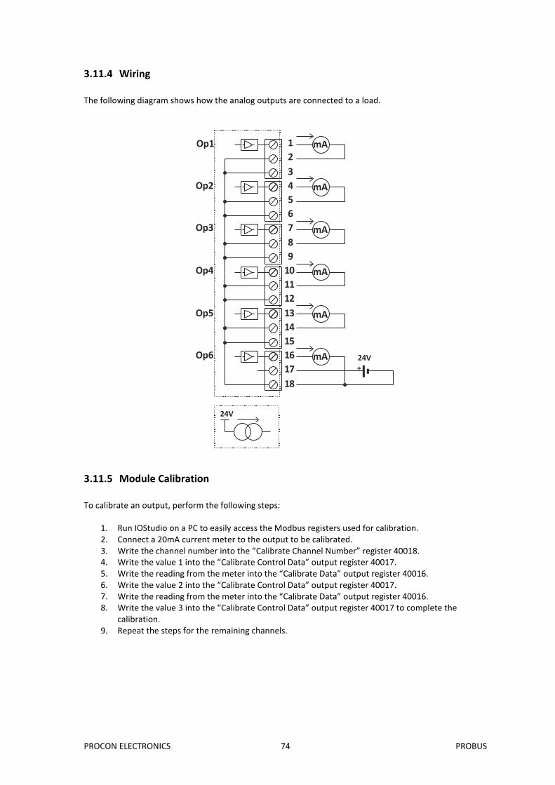
3.11.4 Wiring
The following diagram shows how the analog outputs are connected to a load.
1
2
3
4
5
6
7
8
9
10
11
12
13
14
15
16
17
18
Op1
Op2
Op3
Op4
Op5
Op6+
24V
mA
mA
mA
mA
mA
mA
24V
3.11.5 Module Calibration
To calibrate an output, perform the following steps:
1. Run IOStudio on a PC to easily access the Modbus registers used for calibration. 2. Connect a 20mA current meter to the output to be calibrated. 3. Write the channel number into the “Calibrate Channel Number” register 40018. 4. Write the value 1 into the “Calibrate Control Data” output register 40017. 5. Write the reading from the meter into the “Calibrate Data” output register 40016. 6. Write the value 2 into the “Calibrate Control Data” output register 40017. 7. Write the reading from the meter into the “Calibrate Data” output register 40016. 8. Write the value 3 into the “Calibrate Control Data” output register 40017 to complete the
calibration. 9. Repeat the steps for the remaining channels.
PROCON ELECTRONICS 75 PROBUS
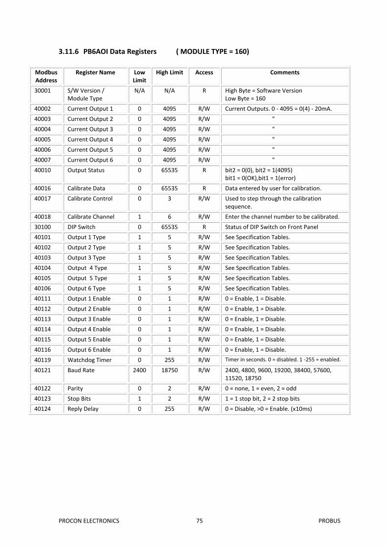
3.11.6 PB6AOI Data Registers ( MODULE TYPE = 160)
Modbus Address
Register Name Low Limit
High Limit Access Comments
30001 S/W Version / Module Type
N/A N/A R High Byte = Software Version Low Byte = 160
40002 Current Output 1 0 4095 R/W Current Outputs. 0 - 4095 = 0(4) - 20mA.
40003 Current Output 2 0 4095 R/W "
40004 Current Output 3 0 4095 R/W "
40005 Current Output 4 0 4095 R/W "
40006 Current Output 5 0 4095 R/W "
40007 Current Output 6 0 4095 R/W "
40010 Output Status 0 65535 R bit2 = 0(0), bit2 = 1(4095) bit1 = 0(OK),bit1 = 1(error)
40016 Calibrate Data 0 65535 R Data entered by user for calibration.
40017 Calibrate Control 0 3 R/W Used to step through the calibration sequence.
40018 Calibrate Channel 1 6 R/W Enter the channel number to be calibrated.
30100 DIP Switch 0 65535 R Status of DIP Switch on Front Panel
40101 Output 1 Type 1 5 R/W See Specification Tables.
40102 Output 2 Type 1 5 R/W See Specification Tables.
40103 Output 3 Type 1 5 R/W See Specification Tables.
40104 Output 4 Type 1 5 R/W See Specification Tables.
40105 Output 5 Type 1 5 R/W See Specification Tables.
40106 Output 6 Type 1 5 R/W See Specification Tables.
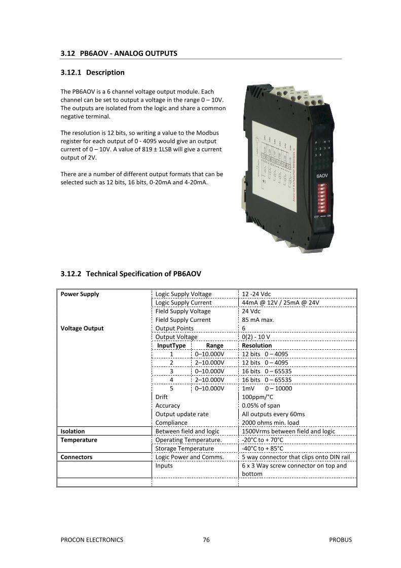
The PB6AOV is a 6 channel voltage output module. Each channel can be set to output a voltage in the range 0 – 10V. The outputs are isolated from the logic and share a common negative terminal. The resolution is 12 bits, so writing a value to the Modbus register for each output of 0 - 4095 would give an output current of 0 – 10V. A value of 819 ± 1LSB will give a current output of 2V. There are a number of different output formats that can be selected such as 12 bits, 16 bits, 0-20mA and 4-20mA.
3.12.2 Technical Specification of PB6AOV
Power Supply Logic Supply Voltage 12 -24 Vdc
Logic Supply Current 44mA @ 12V / 25mA @ 24V
Field Supply Voltage 24 Vdc
Field Supply Current 85 mA max.
Voltage Output Output Points 6
Output Voltage 0(2) - 10 V
InputType Range Resolution
1 0–10.000V 12 bits 0 – 4095
2 2–10.000V 12 bits 0 – 4095
3 0–10.000V 16 bits 0 – 65535
4 2–10.000V 16 bits 0 – 65535
5 0–10.000V 1mV 0 – 10000
Drift 100ppm/°C
Accuracy 0.05% of span
Output update rate All outputs every 60ms
Compliance 2000 ohms min. load
Isolation Between field and logic 1500Vrms between field and logic
Temperature Operating Temperature. -20°C to + 70°C
Storage Temperature -40°C to + 85°C
Connectors Logic Power and Comms. 5 way connector that clips onto DIN rail
Inputs 6 x 3 Way screw connector on top and bottom
PROCON ELECTRONICS 77 PROBUS
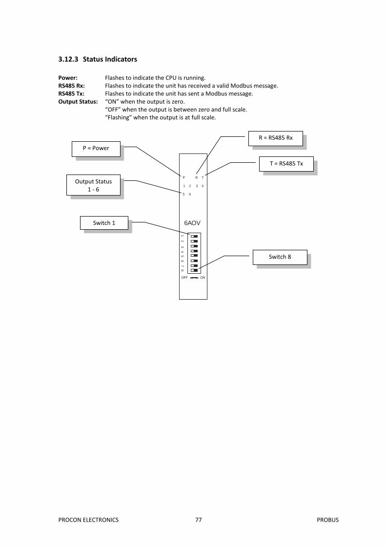
3.12.3 Status Indicators
Power: Flashes to indicate the CPU is running. RS485 Rx: Flashes to indicate the unit has received a valid Modbus message. RS485 Tx: Flashes to indicate the unit has sent a Modbus message. Output Status: “ON” when the output is zero. “OFF” when the output is between zero and full scale. “Flashing” when the output is at full scale.
6AOV
OFF ON
1 2
3 4 5
6 7
8
P R T
1 2 3 4
5 6
R = RS485 Rx
T = RS485 Tx
P = Power
Output Status 1 - 6
Switch 1
Switch 8
PROCON ELECTRONICS 78 PROBUS
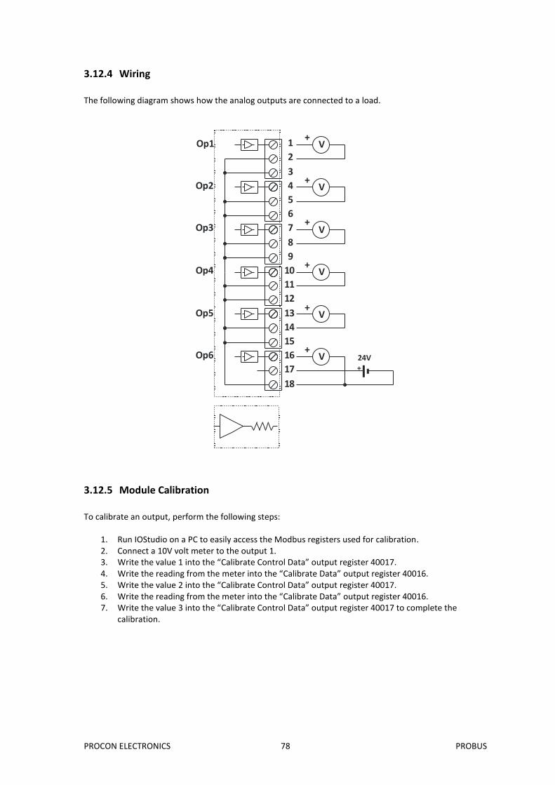
3.12.4 Wiring
The following diagram shows how the analog outputs are connected to a load.
1
2
3
4
5
6
7
8
9
10
11
12
13
14
15
16
17
18
V+
V+
V+
V+
Op1
Op2
Op3
Op4
Op5
Op6
V+
V+
+24V
3.12.5 Module Calibration
To calibrate an output, perform the following steps:
1. Run IOStudio on a PC to easily access the Modbus registers used for calibration. 2. Connect a 10V volt meter to the output 1. 3. Write the value 1 into the “Calibrate Control Data” output register 40017. 4. Write the reading from the meter into the “Calibrate Data” output register 40016. 5. Write the value 2 into the “Calibrate Control Data” output register 40017. 6. Write the reading from the meter into the “Calibrate Data” output register 40016. 7. Write the value 3 into the “Calibrate Control Data” output register 40017 to complete the
calibration.
PROCON ELECTRONICS 79 PROBUS
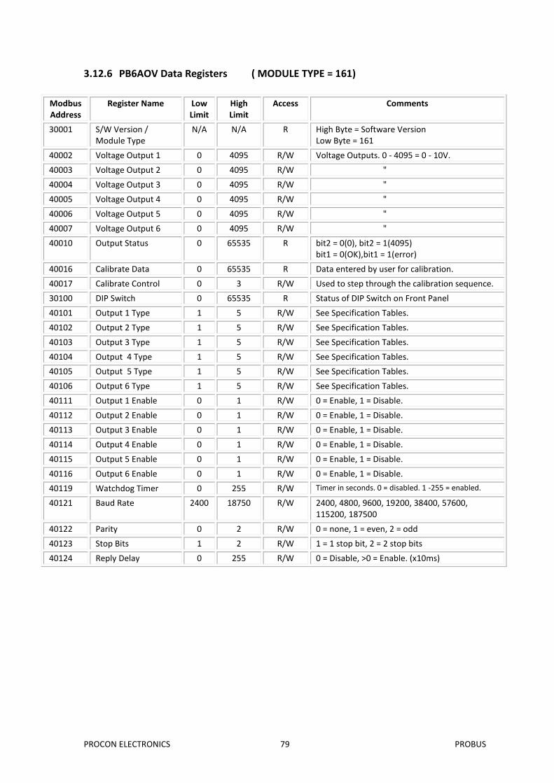
3.12.6 PB6AOV Data Registers ( MODULE TYPE = 161)
Modbus Address
Register Name Low Limit
High Limit
Access Comments
30001 S/W Version / Module Type
N/A N/A R High Byte = Software Version Low Byte = 161
40002 Voltage Output 1 0 4095 R/W Voltage Outputs. 0 - 4095 = 0 - 10V.
40003 Voltage Output 2 0 4095 R/W "
40004 Voltage Output 3 0 4095 R/W "
40005 Voltage Output 4 0 4095 R/W "
40006 Voltage Output 5 0 4095 R/W "
40007 Voltage Output 6 0 4095 R/W "
40010 Output Status 0 65535 R bit2 = 0(0), bit2 = 1(4095) bit1 = 0(OK),bit1 = 1(error)
40016 Calibrate Data 0 65535 R Data entered by user for calibration.
40017 Calibrate Control 0 3 R/W Used to step through the calibration sequence.
30100 DIP Switch 0 65535 R Status of DIP Switch on Front Panel
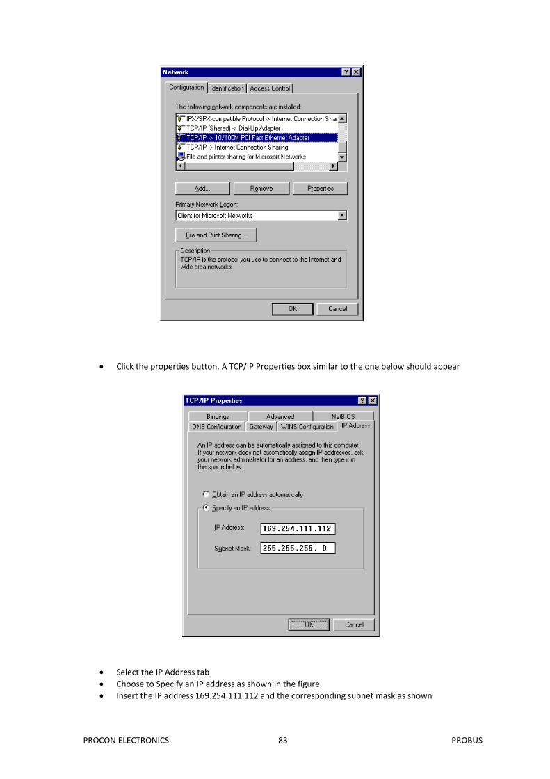
40101 Output 1 Type 1 5 R/W See Specification Tables.
40102 Output 2 Type 1 5 R/W See Specification Tables.
40103 Output 3 Type 1 5 R/W See Specification Tables.
40104 Output 4 Type 1 5 R/W See Specification Tables.
40105 Output 5 Type 1 5 R/W See Specification Tables.
40106 Output 6 Type 1 5 R/W See Specification Tables.
3.13 PBE – MODBUS TCP ETHERNET to MODBUS RS485 GATEWAY
3.13.1 Description
The PBE GATEWAY is an Ethernet to serial converter and connects the PROBUS modules to a 10/100 Base-TX Ethernet network. The PBE GATEWAY includes a web server which enables access to internal parameters for configuration. This allows configuration of IP address, default gateway IP address and subnet mask. The web server can be accessed by most web browsers. The PBE GATEWAY is factory programmed with a default IP address of 169.254.111.111. This address must be changed before the converter is added to an existing network. The web page address for viewing the setup parameters is http://169.254.111.111/index.htm The web page address for configuring the converter is http://169.254.111.111/ip.htm The master device which is polling the modules must be configured with the IP address of the PBE GATEWAY and with the modbus ID of the PROBUS modules. As each PROBUS communications bus is separate, it is possible to have repeated Modbus ID's on the PROBUS modules provided they are attached to a different PBE GATEWAY. The IP address differentiates between the different PROBUS systems. Consequently, many hundreds of PROBUS modules may be added to an Ethernet network. The PBE GATEWAY is a Modbus gateway and the client must be configured to use Port 502. This is a reserved port number for Modbus TCP applications and informs the PBE GATEWAY that it must implement the protocol conversion from Modbus TCP on the Ethernet network to Modbus RTU on the PROBUS serial communications bus.
Temperature Operating Temperature. -20°C to + 70°C
Storage Temperature -40°C to + 85°C
Connectors Logic Power and Comms. 5 way connector that clips onto DIN rail
Humidity Up to 95% non condensing.
PROCON ELECTRONICS 81 PROBUS
3.13.3 Status Indicators
Power: Flashes to indicate the CPU is running. Serial Bus Rx: Flashes to indicate the unit has received a valid Modbus message from a
PROBUS module. Serial Bus Tx: Flashes to indicate the unit has sent a Modbus message to a PROBUS
module. Modbus TCP Rx: Flashes to indicate the unit has received a valid Modbus message on the
Ethernet network. Modbus TCP Tx: Flashes to indicate the unit has transmitted a Modbus message on the
Ethernet network. Web Server: Flashes to indicate the HTTP web server is being accessed.
E
L H M
A
P R T
ETHERNET
R = RS485 Rx
T = RS485 Tx
P = Power
L = Ethernet Link
Ethernet Port
IP address reset switch
A = Ethernet Activity
M = Modbus TCP
H = HTTP Web Server
PROCON ELECTRONICS 82 PROBUS
3.13.4 Configuration
3.13.4.1 Power Connections.
The PBE GATEWAY Module must be clipped onto a DIN rail. Power for the PBE GATEWAY must be applied to terminal 2 (+12/24VDC) and terminal 1 (0V). The power LED will flash and all LED's will be off.
3.13.4.2 Ethernet Connection.
Next the Ethernet connection is required, either through a network or directly to a PC. The Ethernet interface uses a standard RJ45 connector.
3.13.4.3 Connecting To a PC which is not Connected to a Network.
If the PC is equipped with an Ethernet card but not connected to a network, a local network address should be used for communication between the PBE GATEWAY and the PC. The PBE GATEWAY is shipped with a default IP address 169.254.111.111. This address is in the address area reserved for local networks not connected to the Internet. For direct connection between the PC and the PBE GATEWAY, a crossover Ethernet cable is required.
To setup your PC to connect directly to the PBE GATEWAY, an IP address in the same range as the PBE GATEWAY must be assigned to the PC. In Windows environments, this should be done as follows:
Connect the PC and the PBE GATEWAY together using a crossover cable
Open the Windows Control Panel
Select Network
Select TCP/IP -> the PC's Ethernet adaptor from the Configuration tab as shown below
PROCON ELECTRONICS 83 PROBUS
Click the properties button. A TCP/IP Properties box similar to the one below should appear
Select the IP Address tab
Choose to Specify an IP address as shown in the figure
Insert the IP address 169.254.111.112 and the corresponding subnet mask as shown
PROCON ELECTRONICS 84 PROBUS
Save your settings by pressing OK in both TCP/IP properties and Network properties
Reboot your PC
3.13.4.4 Connecting to a PC which is connected to a Network.
If there is an Ethernet network available, the PBE GATEWAY can be connected to any Ethernet connection or hub belonging to the network. If the PC is connected to a network, there is a strong possibility that the default IP address of the PBE GATEWAY is outside the range of the network (the address doesn't belong to the IP subset of the network). If the Ethernet network is connected to the Internet, this is certain. In this case a new IP address for the PBE GATEWAY is required. Contact the local network administrator to be assigned a free IP address for the PBE GATEWAY. The new IP address is programmed into the PBE GATEWAY using a Web browser software such as Internet explorer. In this case the PBE GATEWAY must first be connected directly to a PC as described above. In the remainder of this chapter, the IP address 169.254.111.111 is used as an example. Exchange this IP address with the IP address you have set up in all the occurrences.
3.13.4.5 Testing the Connection
To test the connection between the PC and the PBE GATEWAY, a simple program called ping can be used. Ping sends a number of messages to the specified IP address and displays the response. The ping program can be run from the command line or from a DOS window on the PC, as follows:
Open the Windows Start Menu
Click Run
In the Open box, type: "ping 169.254.111.111" If the network connection is OK, the program will respond with: "Reply from 169.254.111.111" and information about the response time. If there is a problem with the network setup the program will respond: "Destination host unreachable". There may be two solutions to this problem:
If the PC is connected in a network, change the IP address to an address accessible from the local network.
If the PBE GATEWAY is connected directly to the PC(or through a hub), change the PC's IP address to one in the same address range as the PBE GATEWAY.
If there is a problem with the PBE GATEWAY the program will respond: "Request timed out", this means that the PBE GATEWAY can not respond to messages. Check the power connection. Check that the Link LED is illuminated when the cable is plugged into the RJ45 connector.
Lan/ Internet
PROCON ELECTRONICS 85 PROBUS
3.13.5 Viewing Web Pages
The PBE GATEWAY has built in web pages. These are used for checking the configuration and dynamic data, and for altering the configuration. To view these Web pages, a Web browser such as Internet Explorer or Netscape is needed. To view the default Web page in PBE GATEWAY, start the Web browser and type "169.254.111.111" into the address line of the browser window. The main page of the PBE GATEWAY will now be displayed in the browser window. If no Web page is displayed, go back to testing the network connection to the PBE GATEWAY by using the ping command. If the PBE GATEWAY replies to the ping messages, check the setup of the Web browser. If the PBE GATEWAY is directly connected to the same network as the PC, "direct connection to the network" or "bypass proxy server for local addresses" should be selected in the Web browser configuration menu. If the PBE GATEWAY is connected to the PC through a firewall, a proxy server should be selected in the configuration menu. Contact the local network administrator for information about the network configuration.
PROCON ELECTRONICS 86 PROBUS
3.13.6 Troubleshooting Guide.
No Checkpoint Solution
1
Is the LINK LED on and is the ACTIVITY LED flashing with
short pulses?
No
No network connection is detected. The Ethernet cable is either not plugged in or wrong type of cable is used. For connection to a network with a hub or switch, a normal network cable can be used. For direct connection to a PC network card, a twisted cable must be used.
Yes A network connection is detected, the PBE GATEWAY is connected to the network.
2
Does the PBE GATEWAY respond to PING requests?
No
Either the PC or the PBE GATEWAY is setup with wrong IP address. To change the IP address of the PBE GATEWAY back to the default address, remove the power, open the PBE GATEWAY housing and remove the jumper labeled DEFAULT IP. Apply power to the PBE GATEWAY for a short while. Now replace the jumper and close the enclosure. To change the IP address of a PC, use the Windows "control panel -> network -> TCP/IP properties" and setup an IP address close to the PBE GATEWAY address. The PBE GATEWAY is shipped with a default IP address of 169.254.111.111, the PC can be setup with an IP address of 169.254.111.112
Yes
The PC and PBE GATEWAY are setup with a correct IP address and they are able to communicate with each other.
3
Can the default Web page be accessed in a Web
browser?
No
This is normally caused by the setup of the Web browser. In the "options" or "preferences" menu, check that the Web browser is configured for direct network connection or local area network and NOT using a proxy server.
Yes No problems.
PROCON ELECTRONICS 87 PROBUS
3.13.7 Parameter Configuration
The Web page address "169.254.111.111/ip.htm" is entered into the address line of the browser window to access the configuration page. This page allows you to change the IP address of the PBE GATEWAY, Default Gateway, Subnet Mask, and to enter a Module Description Name for identification/maintenance purposes.
PROCON ELECTRONICS 88 PROBUS
Module IP Address: The new IP address can be entered into the web page as shown above. After this has been done, you must click the Submit button to send the values to the Converter Module. The screen will now be updated and if successful will continue to display the new IP address. The new IP address will only be effective after the PBE Gateway power has been switched off and on again. This feature allows you to check that the correct IP address has been entered before being activated. If the IP address has been entered incorrectly and the power has not been switched off, it is possible to re-enter the correct IP address. If the power has been switched off and back on again, the PBE Gateway will not communicate until you enter the new IP address into the address line of the browser window. The push button reset switch on the front of the module is used to reset back to the default factory IP address. Perform the following steps to reset the IP to factory default (169.254.111.111) a. Switch off the power. b. Push and hold the switch. c. Switch on power for 5 seconds. d. Release the switch.
Default Gateway IP Address: A default gateway is a node (a router) on a computer network that serves as an access point to another network. In enterprises, however, the gateway is the computer that routes the traffic from a PC to the outside network that is serving the Web pages. It is only necessary to configure the default gateway IP address if the PC that is accessing the PBE Gateway is on a different network.
Subnet Mask: In computer networks, a subnetwork or subnet is a range of logical addresses within the address space that is assigned to an organization. The subnet mask is used to inform the Converter that it must send its replies to the gateway if the IP address of the PC is on a different network. When the subnet mask is set to “0.0.0.0” then it is effectively disabled and the default gateway is not used. A typical subnet mask would be “255.255.255.0”.
Socket Timeout: If a socket connection is broken, say due to a network fault, it must timeout to free it up so that it can be used again. This timer is triggered by activity on the PBE Gateway, so if there is no communications activity for longer than the timeout period, the socket will close.
Modbus Communications Watchdog: If a value other than zero is entered into this field, the watchdog will be enabled and will be reset every time there is a Modbus message. If there is a break in the Modbus communications which is longer than the timeout value, then the module will be reset.
Baud Rate, Parity, Stop Bits: The configuration of the serial port can be configured by selecting the parameters from the pull-down menu. Note: The power must be cycled to reset the unit after the communication settings have been changed.
Modbus End of Message Timer: The standard way of determining the end of a Modbus message is to time 3.5 characters. (as per the Modbus protocol specification) Some Modbus slaves are not compliant with the Modbus specification and have time delays between characters which would normally result in an error. This field enables the converter to have a longer end of message timeout to be able to function correctly with these slave devices.
Serial Reply Timeout: This timeout is the time the module waits for a reply from a slave device. If a reply is received then this timeout is cancelled and the converter looks for the next TCP message. If the slave does not send a reply, then this timeout will expire and allow the converter to look for the next TCP message. This timeout must be longer than the turn-around time of the slave device or it will timeout before the slave replies.
RS485 On Delay: This is the time the RS485 transmitter will be enabled before data is transmitted.
RS485 Off Delay: This is the time the RS485 transmitter will be enabled after data is transmitted.
Module Name: This field allows you to enter a module description name into the PBE GATEWAY. This is an identifier for diagnostic/maintenance purposes and is chosen to best describe the PBE GATEWAY in the system by name or number.
PROCON ELECTRONICS 89 PROBUS
4. SPECIFICATIONS
4.1 ENVIRONMENTAL
Operating Temperature -20°C to +70°C Storage Temperature -40°C to +85°C Humidity Up to 95% non condensing.
4.2 EMC INSTALLATION INSTRUCTIONS
1. Screened twisted pair RS485 cable must be used with the screen grounded at one point only. 2. The RS485 cable must be terminated at both ends using a 120 ohm resistor. 3. Use should be made of screened I/O, T/C, RTD cable with the screens grounded at one point as
close to the PROBUS module as possible. 4. The PROBUS modules must be installed in an appropriate enclosure inaccessible to the operator
during normal use.
PROCON ELECTRONICS 90 PROBUS
4.3 CONFORMITY CERTIFICATE
DECLARATION OF CONFORMITY
according to EN 45014
Manufacturer’s Name: Procon Electronics Pty Ltd
Manufacturer’s Address: 22/195 Prospect Highway Seven Hills NSW 2147 Australia