60
W H E R E S C I E N C E M E E T S S E R V I C E SYN RC Procedure Manual for MRI of the Brain Baxter Protocol 161003

W H E R E S C I E N C E M E E T S S E R V I C E
SYN RC
Procedure Manual for MRI of the Brain
Baxter
Protocol 161003

Baxter
Protocol 161003
A Phase 3 Randomized, Double-Blind, Placebo-Controlled Study of the Safety and Effectiveness of Immune Globulin Intravenous (Human), 10% Solution (IGIV, 10%) for the Treatment of Mild to Moderate Alzheimer’s
Disease (AD)
Synarc Code: BAXT 2207
Version 1.0
10 November 2011
© 2011 SYNARC Inc. ALL RIGHTS RESERVED.
No part of this work covered by the copyright hereon may be reproduced or used in any form or by any means - graphic, electronic, or mechanical, including photocopying, recording, taping, or information storage and retrieval systems - without
permission of SYNARC Inc.

Procedure Manual for MRI of the Brain Baxter 161003 Protocol
i Version 1.0 – 10 November 2011
Procedure Manual Sign-Off
Dear Study Coordinator and MRI Technologist(s):
Synarc requires that the Study Coordinator and all MRI Technologists involved in the Baxter protocol
161003 study read and fully understand the Procedure Manual for MRI Imaging. This requirement
should be completed before imaging subjects in the 161003 study. All new personnel, who join the
study after site initiation, are also required to read and understand this manual.
Please have all applicable study personnel sign and date this form to confirm completion of this
requirement. Please fax or mail a copy of this form to Synarc and keep a copy for your records.
Synarc Inc.
Baxter 161003 Study Team (BAXT2207)
7707 Gateway Boulevard, 3rd
Floor
Newark, CA 94560
Fax: 415-817-8999
Principal Investigator:
Site Number:
Please indicate who is responsible for submitting packages to Synarc:
Study Coordinator □ Technologist □
Study Coordinator (Study Coordinators are responsible for reviewing and understanding the Logistics portion of this manual.)
Printed Name Signature Initials Date (DD-
MMM-YYYY)
___ ___ ___
___ ___ ___
MRI Technologist (MRI Technologists are responsible for reviewing and understanding the entire manual.)
Printed Name Signature Initials Date (DD-
MMM-YYYY)
___ ___ ___
___ ___ ___
___ ___ ___
___ ___ ___
___ ___ ___
- - Do not remove this page – send a photocopy only- -

Procedure Manual for MRI of the Brain Baxter 161003 Protocol
ii Version 1.0 – 10 November 2011
Table of Contents
PROCEDURE MANUAL SIGN-OFF ............................................................................................................................. I
GLOSSARY AND ABBREVIATIONS ........................................................................................................................ IV
1.0 INTRODUCTION ............................................................................................................................................... 1
2.0 STUDY INTRODUCTION ................................................................................................................................. 2
2.1 STUDY OVERVIEW.............................................................................................................................................. 2
2.2 ROLE OF SYNARC ............................................................................................................................................... 2
2.3 RESPONSIBILITIES OF CLINICAL SITES ................................................................................................................. 3
CONTINUED RESPONSIBILITIES OF CLINICAL SITES: ...................................................................................... 3
2.4 RESPONSIBILITIES OF MRI FACILITIES................................................................................................................. 4
CONTINUED RESPONSIBILITIES OF IMAGING FACILITY: ............................................................................... 4
2.5 CONTRAINDICATIONS FOR THE MRI STUDY......................................................................................................... 4
3.0 MRI STUDY SITE QUALIFICATION PROCESS............................................................................................ 5
3.1 PRE-TRIAL QUESTIONNAIRE ............................................................................................................................... 6
3.2 TELEPHONE TRAINING FOR MRI SITES ................................................................................................................ 6
3.3 MRI INSTRUMENT ASSESSMENT ......................................................................................................................... 6
3.3.1 Pre-study Qualification Phantom Scan ............................................................................................................ 7 3.3.2 First Patient Scan ........................................................................................................................................... 8
4.0 PROCEDURES FOR ACR PHANTOM SCANS ............................................................................................... 9
4.1 PHANTOM SCHEDULING ...................................................................................................................................... 9
4.1.1 Pre-study Qualification Phantom Scan ............................................................................................................ 9 4.1.2 Longitudinal Phantom Scans .......................................................................................................................... 9 4.2 EVALUATION OF PHANTOM SCANS ...................................................................................................................... 9
4.2.1 Requests for Resubmission of Phantom Data .................................................................................................. 9 4.2.2 Requests for Repeat Phantom Scans ..............................................................................................................10 4.3 LABELING PHANTOM IMAGES IN THE DIGITAL HEADER ......................................................................................10
4.4 PHANTOM POSITIONING .....................................................................................................................................10
4.5 PHANTOM SCAN ACQUISITION TECHNIQUE ........................................................................................................11
4.5.1 ACR Sagittal Locator ....................................................................................................................................11
ACR SAGITTAL LOCATOR .......................................................................................................................................11
4.5.2 ACR 11-slice Axial T1-weighted Spin Echo ..................................................................................................12 4.5.3 Slices 1 to 11 of the ACR Axial T1 sequence.................................................................................................13 4.5.4 3D T1-weighted sequence .............................................................................................................................13 4.5.5 Criteria for Assessing Quality of Phantom MRI Scans ...................................................................................14 4.5.6 Clinical sequence parameter check during pre-qualification Phantom MRI Scan ............................................14 4.6 COMMON PROBLEMS .........................................................................................................................................14
4.6.1 Incorrectly (Mis-) prescribed Slices ...............................................................................................................14 4.6.2 Phantom not centered in the Field of View ....................................................................................................15 4.6.3 Geometric Accuracy .....................................................................................................................................15 4.6.4 High Contrast Spatial Resolution ...................................................................................................................16 4.6.5 Image Intensity Uniformity ...........................................................................................................................16 4.6.6 Low Contrast Object Detection .....................................................................................................................17
5.0 PROCEDURES FOR SUBJECT MRI SCANS .................................................................................................18
5.1 PATIENT SCHEDULING .......................................................................................................................................18
5.1.1 First Patient Scan ..........................................................................................................................................18

Procedure Manual for MRI of the Brain Baxter 161003 Protocol
iii Version 1.0 – 10 November 2011
5.1.2 Patient scans .................................................................................................................................................18 5.2 EVALUATION OF SUBJECT SCANS .......................................................................................................................18
5.2.1 Requests for Resubmission of Subject Data ...................................................................................................19 5.2.2 Requests for Repeat Subject Scans ................................................................................................................19
6.0 SUBJECT MRI EXAM PREPARATION .........................................................................................................19
6.1 SUBJECT SAFETY AND MONITORING ..................................................................................................................19
6.2 SUBJECT POSITIONING .......................................................................................................................................19
7.0 SUBJECT MRI ACQUISITION TECHNIQUE ................................................................................................22
7.1 LABELING DIGITAL HEADER FIELDS FOR SUBJECT MRI SCANS ...........................................................................22
7.2 PRE-SCAN ADJUSTMENTS ..................................................................................................................................22
7.3 PROTOCOL FOR MRI OF THE BRAIN ....................................................................................................................22
7.3.1 Localizer: 3-Plane Gradient Sequence (Scouts) and Sagittal Spin Echo ..........................................................23 7.3.2 3D T1 / MP-RAGE / IR-prepped fast SPRR / TFE.........................................................................................24
FIGURE 4. 3D T1 SAGITTAL ORIENTATION AND POSITIONING ......................................................................25
7.3.3 Acquire a Second 3D T1 Sequence ................................................................................................................26 7.3.4 Axial 2D PD/T2 Turbo Spin Echo (TSE) / Fast Spin Echo (FSE) ...................................................................27 7.3.5 Axial 2D FLAIR / T2* Gradient Echo / Diffusion Weighted Imaging (DWI) .................................................28
8.0 COMMON PROBLEMS SEEN WITH SUBJECT MRI SCANS .....................................................................28
8.1 INCORRECT ORIENTATION / IMAGE PLANE MISALIGNMENT .................................................................................28
8.2 SWAP OF READ AND PHASE ENCODING DIRECTIONS ...........................................................................................29
8.3 “GHOSTING” ARTIFACTS ...................................................................................................................................29
8.4 FLOW COMPENSATION.......................................................................................................................................30
8.5 ALIASING (FOLDING) IN 3D T1 ..........................................................................................................................30
8.6 POOR SIGNAL-TO-NOISE RATIO (SNR) AND CONTRAST-TO-NOISE RATIO (CNR) ................................................31
8.7 SIGNAL LOSS ....................................................................................................................................................31
8.7.1 Inferior Slices ...............................................................................................................................................31 8.7.2 Inhomogeneity or Shading Artifact ................................................................................................................32 8.8 METAL ARTIFACT .............................................................................................................................................32
8.9 INADEQUATE HEAD COVERAGE .........................................................................................................................33
9.0 DATA ARCHIVE ONTO DIGITAL MEDIA ...................................................................................................34
10.0 DATA SUBMISSION PROCEDURES ..............................................................................................................34
10.1 SUBMITTING MRI DATA ARCHIVED ON DIGITAL MEDIA .....................................................................................34
10.2 DATA PREPARATION..........................................................................................................................................35
10.3 DATA PREPARATION..........................................................................................................................................35
10.4 SUBMITTING DATA VIA SYNARC’S FTP WEBSITE (SYNARCCONNECT.COM) .........................................................35
11.0 SUPPLIES PROVIDED BY SYNARC ..............................................................................................................36
APPENDIX I: TECHNICAL PARAMETERS FOR MRI OF THE BRAIN ..............................................................37
APPENDIX II: TECHNICAL PARAMETERS FOR ACR PHANTOM SCANS.......................................................44
APPENDIX III: INSTRUCTIONS FOR COMPLETING THE TRANSMITTAL FORM FOR MRI OF THE BRAIN............................................................................................................................................................................51
APPENDIX IV: TRANSMITTAL FORM FOR MRI OF THE BRAIN ...................................................................52
APPENDIX V: TRANSMITTAL FORM FOR ACR PHANTOM MRI .................................................................52
APPENDIX VI: STUDY SUPPLY ORDER FORM ....................................................................................................53

Procedure Manual for MRI of the Brain Baxter 161003 Protocol
iv Version 1.0 – 10 November 2011
Glossary and Abbreviations
Abbreviation Definition ACR American College of Rheumatology AWB Airway Bill CD Compact Disk CT Computed Tomography DCF Data Clarification Form DICOM Digital Imaging and Communications in Medicine DWI Diffusion Weighted Images FLAIR Fluid attenuation inversion recovery FTP File Transfer Protocol GCP Good Clinical Practice IGIV Immune Globulin Intravenous (Human) IPN Incomplete Package Notification MIRRN Medical Image Repeat Request Notification MRI Magnetic Resonance Imaging NCR Non Carbon Required OS Operating System PI Principal Investigator QC Quality Control QRG Quick Reference Guide SC Study Coordinator SE Spin Echo TE Echo Time TF Transmittal Form TI Inversion Time TR Repetition Time YOB Year of Birth

Procedure Manual for MRI of the Brain Baxter 161003 Protocol
1 of 54 Version 1.0 – 10 November 2011
1.0 Introduction
The purpose of this manual is to standardize MRI image acquisition procedures between the sites
participating in the Baxter 161003 study.
All radiologists and technologists contributing to this study are expected to have had appropriate
theoretical and practical training in MRI. Study personnel should also satisfy all local requirements for
radiology licensing and registration. For the safety of subjects and technologists alike, an
understanding of radiation risks and radiation safety procedures is also required. Utilizing qualified
radiology personnel is the first step toward the successful use of medical imaging in this study. The
procedure manual is designed for the study coordinator and the MRI technologists involved in this
study. All new personnel, who join the study after site initiation, are also required to read and
understand the manual, and return the manual sign-off on Page i.
This manual, taken alone, should not be considered as sufficient training in the proper technique for
acquiring MRI images. The goal of the manual is to define a standard procedural approach for
acquiring MRIs of sufficient quality for achieving the study goals.
Questions regarding this manual or MRI techniques should be directed to:
BAXTER 161003 Study Team (BAXTER 2207) Synarc Inc.
Baxter 161003
7707 Gateway Boulevard, 3rd
Floor
Newark, CA 94560
Tel: 415-817-8900
Fax: 415-817-8999
Email : [email protected]
HOURS: 9.00 – 17.00 Pacific Time

Procedure Manual for MRI of the Brain Baxter 161003 Protocol
2 of 54 Version 1.0 – 10 November 2011
2.0 Study Introduction
2.1 Study Overview
Structural imaging will be used in the 161003 protocol to evaluate the effect of IGIV, 10% on the rate
of Alzheimer’s disease progression in the brain using various volumetric measurements.
It is anticipated that approximately 402 subjects at 65 sites worldwide will participate in the study.
Each subject will have MRI scans acquired at Baseline, 9-Month, and 18-Month, or upon Early
Termination.
Unscheduled MRI scans might also be acquired during the course of the study and sent to Synarc for
evaluation. All Unscheduled visits should be pre-approved by Baxter. For all unscheduled MRI
visits, the site should contact their Field CRA’s in order to obtain approval from Sponsor.
MRI is the most sensitive method for determining the incidence of brain atrophy and for monitoring
the progression of neurodegeneration both across the whole brain and in specific structures. The
objective of the MRI study is to provide supporting evidence that IGIV, 10% attenuates the underlying
pathologic process of AD by assessing rate of decline in Whole Brain Atrophy, Ventricular Volume,
Hippocampal Volume, and Entorhinal Cortical Volume.
2.2 Role of Synarc
Synarc’s Primary Responsibilities to Site
• Qualify MRI facilities into the study. Synarc will conduct an initial MRI Instrument
Assessment through the evaluation of Pre-Trial Questionnaires, American College of
Radiology (ACR) phantom scans, and First Patient Qualification scans.
• Conduct trainings for MRI Technologists on the MRI acquisition procedures specific to the
Baxter MRI study.
• Provide Study Manual and Quick Reference Guides (QRG) for subject and phantom
scanning.
• Evaluate subject scans and submit timely Quality Control Reports (as defined in Section 5.0,
“Evaluation of Subject MRI Scans”
Continued responsibilities are to:
• Collect and archive exams.
• Verify that the sequence parameters used to acquire phantom and subject MRI exams are in
agreement with the study procedure manual.
• Review the quality of the subject MRI images for adequate anatomical coverage, signal-to-
noise ratio, and the presence of artifacts.
• Submit quality control (QC) reports to the study coordinator and MRI facility detailing any
issues regarding image quality found during phantom and subject scan QC along with
suggestions for improvement.
• Provide ongoing support and feedback to clinical sites and MRI facilities.
Procedure Manual for MRI of the Brain Baxter 161003 Protocol
3 of 54 Version 1.0 – 10 November 2011
Synarc personnel will review the quality of all MRI data submitted. It is expected that the majority
of examinations received will be of acceptable quality. If any problems are detected related to
image quality, Synarc will notify the responsible clinical site and the MRI facility via fax, email or
phone, suggest possible causes of the problem, and offer potential solutions. The MRI facility
should try to correct these errors and avoid them in future exams. Despite this review, the
acquisition of MRI scans of acceptable quality remains the responsibility of the MRI facility.
2.3 Responsibilities of Clinical Sites
Primary Responsibilities of Clinical Sites
• Ensure that patients enrolling in this study do not have any MR contraindications and that
patients are good candidates for tolerating an MRI scan and possible repeat exams.
• Schedule subject exams for all visits in conjunction with the MRI technologist.
• During site initiation, patients should only be scheduled after the site has received training
from Synarc and submitted a passing phantom scan and a passing first patient scan (see
Sections 3.3.1 and 3.3.2 of this manual). For the duration of the study, patients should avoid
being scheduled and scanned when there is a pending repeat request for a phantom scan (see
Section 4.2.2).
• Provide all subject demographic and exam information to the MRI technologist so that this
information is entered completely and correctly on the MRI Transmittal Form that is
submitted with the data.
• Ensure that MRI data and corresponding Transmittal Form are submitted to SYNARC within
24-hours of acquisition.
Continued responsibilities of Clinical Sites:
• Confirm receipt of Synarc supplies and distribute these supplies to the appropriate study
personnel, based on defined roles in the data acquisition and submission process.
• Notify Synarc when all subjects enrolled in the study have completed an 18-Month or Early
Termination MRI scan.
• Ensure that the MRI personnel have a copy of the “Quick Reference Guide for Acquiring MRI
of the Brain.”
• Do not proceed with scanning or scheduling additional subjects until MRI facility has been
approved by Synarc.
• Ensure that MRI facility is performing and submitting longitudinal phantom scans.
• Notify Synarc about planned upgrades at the MRI facility or other issues that might
compromise the consistency MRI scanning over time.

Procedure Manual for MRI of the Brain Baxter 161003 Protocol
4 of 54 Version 1.0 – 10 November 2011
2.4 Responsibilities of MRI Facilities
Primary Responsibilities of MRI Facility
• Acquire MR scans for phantoms and subjects in compliance with Synarc’s procedures and
imaging protocol detailed in the “Procedure Manual for MRI Imaging of the Brain.”
• Verify that all subject demographic and exam information are entered completely and correctly
on the MRI Transmittal Form that is submitted with the MRI data.
• Verify that the electronic MRI header is entered completely and correctly and in compliance with
privacy laws to ensure and protect the confidentiality of the patient (no patient names or identifiers).
• Send MRI data and corresponding Transmittal Form to SYNARC within 24-hours of
acquisition.
• Submit Longitudinal ACR Phantom scan every three months until the end of the study (as
defined in Section 4.1.2, “Longitudinal Phantom Scans”).
Continued responsibilities of imaging facility:
• Confirm that all MRI technologists who will be performing scans for the Baxter 161003
protocol are properly trained on the study-specific acquisition parameters and data submission
procedures.
• Scan ACR phantom and perform system calibrations at the beginning of the study.
• Do not scan patients until an approved pre-study phantom QC report has been received from
Synarc.
• Do not scan additional patients until a passing First Patient Qualification Scan QC report has
been received from Synarc.
• Review exam quality and obtain repeats as necessary.
• Maintain an archive of subject and phantom MRI exams.
• Notify Synarc immediately as soon as they are aware that a hardware or software upgrade is
scheduled. Synarc will evaluate the planned upgrade and provide feedback to the facility as to
whether this will compromise volumetric analysis.
* In some cases, the responsibilities of the Clinical Site and the MRI facility overlap. We ask that the
Study Coordinator work with the lead technologist to decide how overlapping responsibilities will be
assigned (for example, who will fill out Transmittal Forms and mail data to Synarc). At site training,
Synarc will document which party is responsible for these activities for the duration of the study.
2.5 Contraindications for the MRI Study
Subjects may not undergo MR scans with certain contraindications. It is the responsibility of the MR
imaging technologist or Radiologist to check for all contraindications. If a contraindication is found for
a subject, that subject shall not be scanned and the MR facility shall report this finding to the Clinical
site.
Procedure Manual for MRI of the Brain Baxter 161003 Protocol
5 of 54 Version 1.0 – 10 November 2011
3.0 MRI Study Site Qualification Process
Synarc will assist in identifying and qualifying facilities for participation in the study. To be
considered for participation, MRI facilities must meet the requirements listed in the box below:
Preliminary Requirements for Imaging Facilities
• MRI scanner must have a magnetic field strength of 1.5 Tesla ONLY.
• MRI scanner must meet certain requirements with regards to hardware and/or software.
• No major hardware or software upgrades that would compromise volumetric analysis of
existing subject scans.
• MRI scanner must be manufactured by Siemens (Symphony, Espree, Avanto or Aera),
General Electric (Excite or MR450), or Philips (Intera, Achieva or Ingenia). Certain older
vendor release levels will not be allowed.
• Facilities must have a volumetric head coil.
− Phased-array head (multiple channels) coils may be allowed under conditions as
defined by Synarc. The site may NOT change RF coil once approved. Surface
coils cannot be used to acquire any scans for this study.
• MRI software must be capable of acquiring the 3-D sequence as specified for a given
scanner.
• Facilities must be able to digitally archive data on CD or FTP in uncompressed DICOM
format.
• Facilities must be able to perform the required MRI scans using the Technical Parameters
specified in Appendices I and II of the MRI Procedure manual.
• MRI Scanner to be used for the study should not be a mobile MRI scanner or must not be
moved during the study.
• Only one MR scanner may be used at a facility and the scanner may not be switched during
the length of the study.
MRI facilities that meet the requirements listed above will then advance through subsequent
qualification procedures. An overview of the complete Site Qualification procedure is detailed below:
1. Pre-Trial Questionnaire: MRI facility must complete and submit a Synarc Pre-Trial
Questionnaire.
2. Telephone Training: Primary MRI technologists must complete a telephone-training with
Synarc to ensure comprehension of and adherence to MRI protocol and procedures.
3. MRI Instrument Assessment:
a. Pre-Study ACR Phantom Scan – Upon completion of telephone training, site will be
asked to perform an ACR Phantom Scan.
b. Patient Scan – Upon the approval of an ACR phantom scan, the site will be asked to
perform a First Patient Scan.
The clinical site and MRI facility will be notified of its complete eligibility to participate in the MRI
study once Synarc has received and reviewed all of the MRI Instrument assessment data.

Procedure Manual for MRI of the Brain Baxter 161003 Protocol
6 of 54 Version 1.0 – 10 November 2011
3.1 Pre-Trial Questionnaire
Site Questionnaires will be collected from each MRI facility considered for participation in the Baxter
161003 study. The questionnaire will ask for information about the MRI technologists as well as the
MRI equipment.
Although several technologists may work on this study from one site, the MRI facility must designate
one MRI technologist to be the Primary MRI Technologist to work on this study. The responsibility of
the Primary Technologist is to ensure that the imaging protocol is followed when acquiring any subject
or phantom scans for this study, as well as to ensure that other MRI technologists acquiring images for
this study read and understand the procedures detailed in this manual.
IMPORTANT ► If the Primary MRI Technologist leaves the MRI facility, it is the
responsibility of the MRI facility to ensure that he/she trains the
replacement technologist on the protocol provided by this manual. A
complete manual sign-off is required from the new personnel. Should the
new personnel have any questions, they may contact Synarc.
3.2 Telephone Training for MRI Sites
Once Synarc has received the completed Pre-Trial Questionnaire and determined that the site meets the
“Preliminary Requirements for MRI Facilities” (as defined in Section 3.0, “MRI Study Site
Qualification Process”), a 45-60 minute telephone training will be scheduled with the technologists at
each site. The goal of the telephone training is to:
• Instruct sites on study specific protocols for acquiring acceptable MRI images of the brain and phantom.
• Allow for troubleshooting of potential common problems.
• Explain the submission process of MRI data to Synarc.
IMPORTANT ► Sites are not allowed to acquire subject MRI exams until they have received
training from Synarc and have submitted an acceptable ACR Phantom scan.
3.3 MRI Instrument Assessment
The overall purpose of the MRI Instrument Assessment is to detect and reduce measurement noise on
one scanner per site, and to minimize scanner differences between sites, ensuring the most standard
and reliable data for volumetric analysis. The Phantom and First Patient assessments are critical,
because each provides unique information about scanner performance that allows the evaluation,
optimization and correction of scan parameters.

Procedure Manual for MRI of the Brain Baxter 161003 Protocol
7 of 54 Version 1.0 – 10 November 2011
3.3.1 Pre-study Qualification Phantom Scan
Each site is required to use an American College of Radiology (ACR) phantom to perform all
phantom test-run scans. If a site’s MRI facility does not have an ACR phantom, Synarc will
provide one for the duration of the study.
An ACR phantom test scan is collected for the following purposes:
• To assess important instrument parameters, including gradient fidelity and signal-to-noise ratio
(SNR), and to determine whether scanner performance is acceptable for the study. The purpose
of phantom test scans is to reduce the measurement noise due to instrument variability.
• To calibrate important instrument parameters, including image resolution and gradient linearity
over field of view, and to minimize differences between scanners. The purpose of system
calibration is to minimize these measurement errors.
• Check the clinical scanning parameters on the ACR phantom during pre-qualification to insure
that: 1) the scanner can perform the desired clinical sequences and 2) the correct clinical
sequences are stored properly in the scanner’s preset protocol section.
• The following sequences will be run for the Pre-qualification scan:
Localizer 3-Plane Gradient (optional, used to assess phantom positioning)
ACR single slice Sagittal Spin Echo
ACR 11 slice Axial T1-weighted Spin Echo
3D T1-weighted sequence as specified in this manual and/or Quick Reference Guide (QRG):
MP-RAGE (Siemens), IR-prepped fast SPGR (GE), 3D TSE (Philips). Note: All GE
scanners use the coronal plane, while all Philips and Siemens scanners use the sagittal
plane.
2D Axial TSE/FSE dual echo
2D Axial FLAIR
2D Axial T2* gradient echo
The imaging protocol required for the ACR phantom scan is different from the protocol used for
subject scans. Refer to Appendix II, “Scanning Protocol for ACR Phantom Scans” for the exact
scanning parameters of each sequence.
* Please note that once a facility qualifies for participation in the MRI study, it will need to repeat the
phantom test scans every three months (as described in Section 4.1.2, “Longitudinal Phantom Scans”)
until the last patient has received an 18-Month / Early Termination scan. The longitudinal phantom
scans only require the first 4 sequences above, eliminating the last 3 which are only used to evaluate
the safety sequence parameters before the first patient is scanned.
The pre-study ACR phantom test scan sent to Synarc will be evaluated by a radiologist or specially-
trained technologist who will assess the phantom images. The results of the pre-study ACR phantom
test scan will be sent to the site within seven (7) business days after receipt of the phantom test scan.
Synarc may request up to two (2) repeats of the pre-study ACR phantom test scan. Repeat requests will
be made by contacting the site’s Study Coordinator via telephone and/or email, and followed up by a

Procedure Manual for MRI of the Brain Baxter 161003 Protocol
8 of 54 Version 1.0 – 10 November 2011
“Phantom QC Report” sent to both the study coordinator and MRI facility. The “Phantom QC Report”
will state a request for the ACR phantom repeat, the reason for the repeat request and detailed
information regarding the image quality and suggestions for improvement. Repeat exams requested by
Synarc should be performed as quickly as possible.
A site is permitted only two repeats for the pre-study ACR phantom scan. Failure of a second
repeated ACR Phantom scan may result in exclusion from the volumetric MRI study. Only upon
receipt of a passing Phantom QC report may a site continue with the next qualification procedure,
the First Patient Scan.
3.3.2 First Patient Scan
After an acceptable phantom test scan has been received, Synarc will request one patient scan. This
scan will undergo a specific set of analyses to determine measurement reliability and reproducibility,
thus ensuring the most accurate data possible across multi-site measurements. These scans differ from
the ACR Phantom scans in their ability to account for the interactions between patient and scanner
(i.e., local intensity variations due to dielectric tissue effects or local geometrical image distortions due
to tissue susceptibility), which can induce substantial noise.
The First Patient Scan will be done on a study patient and uses all the specified imaging sequences for
scanning study patients. Refer to Appendix I, “Technical Parameters for MRI of the Brain”, for the
exact scanning parameters for each sequence.
1. Localizer: 3-plane gradient echo (GRE)
2. 2D Sagittal Spin Echo (SE)
3. 3D T1/ MP-RAGE (Siemens)/ (GE) IR-prepped fast SPGR (GE) / TFE (Philips)
4. Repeat 3D T1 sequence with identical parameters as in sequence #3.
5. 2D Axial Dual echo PD/T2 TSE (Siemens and Philips)/FSE (GE)
6. 2D Axial Fluid-Attenuated Inversion Recovery sequence (FLAIR)
7. 2D Axial T2* Gradient Echo
8. 2D Axial Diffusion Weighted Imaging (DWI)
The results of the First Patient Scan will be faxed to the site within seven (7) business days after
Synarc receives the data. This report, if appropriate, will note any technical deviations from protocol
and offer potential suggestions for the improvement of image data.
Synarc may request up to two repeats of the First Patient Scan. Repeat requests will be made by
contacting the site’s study coordinator by telephone and/or email, and followed up by a “Patient QC
Report” sent to both the Study Coordinator and the MRI facility. Detailed information regarding the
image quality, as well as suggestions for improvement, will be noted on the “Patient QC Report”. In
the event that a patient is not recommended for a repeat, a scan from a different subject may be
submitted to Synarc for purposes of qualification.
IMPORTANT ► A site may not proceed in scanning any additional patient until an
acceptable “Patient QC Report” is received from Synarc. Once the First
Patient Scan requirement is satisfied, the site can start scheduling
additional patients.
Procedure Manual for MRI of the Brain Baxter 161003 Protocol
9 of 54 Version 1.0 – 10 November 2011
4.0 Procedures for ACR Phantom Scans
The phantom MRI scan will be acquired using a uniform scanning procedure in order to account for
and minimize differences in MRI systems across study sites. The images should be acquired in strict
accordance with Synarc’s Technical Parameters, as described in Appendix II, “Technical Parameters
for ACR Phantom Scans”. This phantom has been designed to be used for accreditation of sites in the
US and is used to measure a standard set of parameters that relate to the performance of the scanner
and further compare with other similar scanners. This is critical to evaluating data from multi-center
trials.
Each site is REQUIRED to use an ACR phantom to perform all phantom test scans. If the MRI
facility does not have an ACR phantom, Synarc will provide one to use for the duration of the
study.
IMPORTANT ► THE SAME ACR PHANTOM MUST BE USED WHEN
PERFORMING THE PHANTOM SCANS THROUGHOUT THE
COURSE OF THIS STUDY.
4.1 Phantom Scheduling
4.1.1 Pre-study Qualification Phantom Scan
The pre-study Qualification Phantom scan will be preformed and submitted upon Synarc’s
acknowledgement of an acceptable Pre-Trial Questionnaire and successful completion of the primary
MRI Technologist’s telephone training. Synarc will then evaluate the qualification scan and provide a
QC report to the Site/MRI facility. Upon receiving a passing Pre-study Phantom QC report, the site
will need to acquire the same scan at three month intervals for the duration of the study.
4.1.2 Longitudinal Phantom Scans
Longitudinal phantom scans will be performed every three (3) months for the duration of the MRI
portion of the study as an assessment of the reproducibility of protocol measurements over time.
These repeated calibration checks will provide evidence of systematic measurement errors due to
system drift degradation or change. The planned acquisition dates of Longitudinal Phantom scans can
be calculated at three month intervals from the scan date of the first accepted Pre-Study Qualification
Phantom Scan.
A failed Phantom QC will most likely result in a repeat request to verify if there is a problem with
the scanner. If the problem turns out to be legitimate, patient data submitted during the period from
the last successful phantom QC may not be useable for volumetric analysis.
4.2 Evaluation of Phantom Scans
If the phantom data can be loaded and viewed, a QC report listing results from the image quality
review will be communicated to the MRI facility within seven (7) business days of receipt for both
Pre-Study Qualification and Longitudinal phantom data.
4.2.1 Requests for Resubmission of Phantom Data
If the submitted phantom data cannot be loaded and viewed on the image viewing stations at Synarc, a
Resubmission Request will be made to the site’s study coordinator and MRI facility identifying the

Procedure Manual for MRI of the Brain Baxter 161003 Protocol
10 of 54 Version 1.0 – 10 November 2011
specific scan and the need for resubmission. The MRI data must be resubmitted to Synarc as quickly as
possible.
4.2.2 Requests for Repeat Phantom Scans
If the data is able to be loaded and viewed, and is still deemed unacceptable for use in this study,
Synarc will make a Repeat Request. The “Phantom QC Report” will be sent to both the Study
Coordinator and MRI facility. The “Phantom QC Report” will state a request for the phantom MRI
repeat, the reason for the request, detailed information regarding the image quality, and suggestions for
improvement.
4.3 Labeling Phantom Images in the Digital Header
On the device, subject and visit information should be entered as follows:
FIELD:
SUBJECT NAME: Enter Site Number - [PHANTOM]
Example: 02 – PHANTOM
DATE OF BIRTH: Enter scan date
WEIGHT: Enter 100 lbs or 50 kg.
STUDY DESCRIPTION: Enter [ACR PHANTOM SCAN]
4.4 Phantom Positioning
In order to ensure the reproducibility of the measurements that are taken throughout the study trial
period, the ACR phantom must be placed inside the MRI magnet in the exact same position every time
it is scanned. This should be accomplished by:
• Aligning the phantom as a head would be aligned. On the phantom, the words “NOSE” and “CHIN” should be positioned where the nose and chin would be for a head study.
• Using the crossed black lines on the phantoms anterior side as a landmark to line up the phantom in the center of the head coil.
• Leveling to ensure that the phantom is horizontal and that the plastic bar on the “CHIN” side is horizontal. Use a plastic bubble level, if available.
• Ensuring that the crosshairs engraved on the phantom are placed at the magnet’s isocenter.
• If using a phased array coil which is not open at the upper end, push the phantom in as far as
possible while still using the patient headrest holder. The “inferior” end of the phantom should
be at least flush with the end of the coil if not inside the coil. If necessary, remove the head
cradle and pad from the coil.
Software Upgrades
If a software upgrade is planned for a scanner, Synarc may request that additional phantom scans be
acquired before and after the upgrade to ensure consistency of scanner performance.

Procedure Manual for MRI of the Brain Baxter 161003 Protocol
11 of 54 Version 1.0 – 10 November 2011
• Note: for phased array coils with non-removable head holder sections, it may not be possible to
use this coil for the phantom scans. In this case, use your quadrature type coil for the phantom
but you can use the phased array coil for the patients.
4.5 Phantom Scan Acquisition Technique
Ensure that the phantom is at room temperature before scanning (T1 and T2 are temperature
dependent). If this is not done, ghosting artifacts may be present in the images. Position slices in the
center of the phantom. Note: the last 4 scans in the list below are ONLY DONE FOR PRE-
QUALIFICATION and need not be included for longitudinal submissions.
The phantom MRI scans will consist of the following imaging sequences:
1. Localizer 3-Plane Gradient
2. ACR single slice Sagittal Spin Echo
3. ACR 11 slice Axial T1-weighted Spin Echo
4. 3D T1 MP-RAGE (Siemens), IR-prepped fast SPGR (GE), 3D TSE (Philips). NOTE: All GE
scanners use the coronal plane, while all Philips scanners, Siemens scanners use the sagittal plane.
5. 2D Axial TSE/FSE dual echo (Pre-qualification only)
6. 2D Axial FLAIR (Pre-qualification only)
7. 2D Axial T2* gradient echo (Pre-qualification only)
8. 2D Axial DWI (Pre-qualification only)
Note: The imaging protocol required for the ACR phantom scan is different from the protocol used for
subject scans. Refer to Appendix II, “Technical Parameters for ACR Phantom Scans” for the exact
scanning parameters of each sequence.
4.5.1 ACR Sagittal Locator
The ACR Sagittal Locator acquisition is a 20 mm thick single-slice spin-echo acquisition through the
center of the phantom and should appear as pictured in the image below.
ACR Sagittal Locator
Notice that the 45° crossed wedges on the left of this image appear with equal intensity.
If the image you acquire does not appear like this, the phantom must be re-centered and re-imaged.

Procedure Manual for MRI of the Brain Baxter 161003 Protocol
12 of 54 Version 1.0 – 10 November 2011
4.5.2 ACR 11-slice Axial T1-weighted Spin Echo
The 11-slice ACR Axial T1 series must be prescribed on the ACR Sagittal Locator as pictured in the
image below.
The center of the first slice must be aligned with the vertex of the crossed wedges and through the
center of the dark chemical shift and resolution insert. The centers of slices 8 through 11 must align
with the four low-contrast disc inserts. The center of slice 11 must be aligned with the vertex of the
crossed wedges. If the slices of the ACR Axial T1 Sequence are not prescribed as pictured above,
the slices must be re-prescribed and the acquisition must be repeated.
This image illustrates the correct alignment of the slices of the ACR Axial T1 sequences on the
ACR Sagittal Spin Echo.

Procedure Manual for MRI of the Brain Baxter 161003 Protocol
13 of 54 Version 1.0 – 10 November 2011
4.5.3 Slices 1 to 11 of the ACR Axial T1 sequence
The collection of images above shows the correctly positioned 11 slices of the ACR Axial T1
sequence. Note that it is possible that the phantom may look different in slices 1-4 if the spacers are
different. This makes no difference to the analysis.
Examine all 11 images and verify that all are present, properly positioned and free of image artifacts.
Quality Evaluation
Slice 1: High Contrast Spatial Resolution, Slice Thickness, Geometric Accuracy
Slice 5: Geometric Accuracy
Slice 7: Image Intensity Uniformity , Percent Signal Ghosting
Slice 8-11: Low Contrast Object Detectability
4.5.4 3D T1-weighted sequence
Acquire the 3D sequence (3D T1 MP-RAGE (Siemens), IR prepped fast SPGR (GE) or 3D TSE
(Philips) Sequence) listed in Appendix II or the QRG for your scanner. All GE scanners use a coronal
acquisition. All Philips and Siemens scanners use the sagittal plane. Be sure to use the exact sequence
listed in Appendix II or the QRG without change.

Procedure Manual for MRI of the Brain Baxter 161003 Protocol
14 of 54 Version 1.0 – 10 November 2011
Use the 3 Plane localizer, sagittal or axial images to plan the 3D sequence. Be sure to cover the entire
volume of the phantom.
4.5.5 Criteria for Assessing Quality of Phantom MRI Scans
Specially trained SYNARC technologists will evaluate if the MRI scanner is performing according to
the Synarc’s specifications. The following four (4) standard ACR measurements will be performed on
the data from each ACR phantom scan:
• 2D- and 3D-Geometric Accuracy: Measures the degree of geometrical distortions in an image,
generated by the MRI system.
• High Contrast Spatial Resolution: Assesses the scanner’s ability to resolve small structures.
• Image Intensity Uniformity: Assesses the scanners ability to yield constant uniform image
intensity in uniform regions of the brain.
• Low Contrast Object Detection: Assesses the extent to which objects of low contrast are
discernable in the images.
Each measurement must fall within a range defined by the American College of Radiology in order for
the phantom test run to be of acceptable quality. Results of the phantom scan QC will be faxed and/or
emailed to the study coordinator and MRI technologist, within seven (7) business days after receipt of
the phantom image data at Synarc.
4.5.6 Clinical sequence parameter check during pre-qualification Phantom MRI Scan
In addition to the ACR and 3D T1 sequences to be used for performance checks, the clinical sequences
for dual echo TSE/FSE, FLAIR, and T2* must also be run on the phantom to check for correct
parameters. The accepted parameters for the clinical scans plus the 3D T1 can then be stored in the
protocol section for use with clinical subjects.
4.6 Common Problems
The purpose of this section is to enable sites who have received a failed “Phantom QC Report” from
Synarc to understand the significance of the failure and understand the steps necessary to correct
problems detected. Errors can occur in any of the measurements listed in 4.5.5, “Criteria for Assessing
Quality of Phantom MRI Scans”, as well as in the positioning of the phantom and of the sequences.
4.6.1 Incorrectly (Mis-) prescribed Slices
Each of the measurements performed on the ACR phantom images requires a specific imaging slice to
make the measurement on. Therefore, mis-prescribing the slices on the phantom may prevent proper
measurement of the phantom since a particular measurement may not be possible if a sequence slice
was not obtained correctly.
Possible Remedies:
• Please refer to Section 4.5.1 “ACR Sagittal Locator” and Section 4.5.2, “ACR Axial T1-Weighted
Sequence”, which details the correct method for aligning the slices in the phantom.

Procedure Manual for MRI of the Brain Baxter 161003 Protocol
15 of 54 Version 1.0 – 10 November 2011
4.6.2 Phantom not centered in the Field of View
This image demonstrates an example of a phantom that is incorrectly positioned in the magnet. It is
off center, and is too low in the field of view.
If the ACR phantom is not correctly positioned within the magnet, the correct slices needed to make
measurements can easily be mis-prescribed.
Possible Remedies:
• Please refer to Section 4.4, “Phantom Positioning”, which details the proper method for positioning the ACR phantom within the scanner.
4.6.3 Geometric Accuracy
The Geometric Accuracy measurement is performed on images from the ACR Sagittal Spin Echo and
the ACR Axial T1-weighted sequence. These measurements detect any distortions in the MR images
obtained which result in the image dimensions being either smaller or larger than the object truly is.
This distortion compromises the sensitive measurements that are being assessed for this MRI study.
Possible Remedies:
• A geometric accuracy failure is most commonly due to mis-calibrated gradients. Gradient
calibration can drift over time. Therefore, it is important that the scanner’s service engineer
recalibrate the gradients after a failed phantom scan result. This recalibration must match exactly
190 mm +/- 2

Procedure Manual for MRI of the Brain Baxter 161003 Protocol
16 of 54 Version 1.0 – 10 November 2011
the pre-screening scan measurements to ensure accurate co-registration of the patient images.
4.6.4 High Contrast Spatial Resolution
The High Contrast Spatial Resolution measurement assesses the magnet’s ability to resolve small
objects. This measurement is highly important for this MRI study as the volumetric measurements
made on patient images will be done on small structures of the brain such as the hippocampus and
entorhinal cortex.
The images below show an example of phantom images that (a) Passed the High Contrast Spatial
Resolution test and one that (b) Failed the test.
(a) Passed (b) Failed
Possible Remedies:
• Make sure the phantom is stable in the head coil and not free to move or vibrate.
• Image “ghosting” due to maladjustments and instabilities can cause the resolution of small images
to be compromised. As mentioned in Section 8.3, “Ghosting Artifacts” it may be necessary to
request the service engineer to determine and correct the cause of the ghosting.
• Check that any user selected image filters are turned off. Excessive image filters may make the
images appear less noisy, but will “smooth” the images and compromise the resolution. Therefore,
turn off the filters to correct errors in high contrast spatial resolution.
• Check that the phantom is not tilted; this can cause blurring of these objects.
• Check that the correct number of phase encoding steps is used (see Appendix II or QRG).
4.6.5 Image Intensity Uniformity
The Image Intensity Uniformity measurement assesses image uniformity in a large uniform circular
region of the phantom. Failure of this test may indicate a defective head coil or problem in the radio-
frequency subsystems.
Possible Remedies:
• Make sure the phantom is centered in the head coil. If the phantom is closer to one side of the head
coil than the other, uneven image intensities can result.
• Make sure the phantom is stable in the head coil and not free to move or vibrate.

Procedure Manual for MRI of the Brain Baxter 161003 Protocol
17 of 54 Version 1.0 – 10 November 2011
• Image “ghosting” due to maladjustments and instabilities can cause image intensity variations. If
ghosting is suspected, call your service engineer (as defined in Section 8.3, “Ghosting Artifact” and
Section 4.6.4, “High Contrast Spatial Resolution”).
• If the images also appear grainy (i.e. a low signal-to-noise ratio), then the problem could be with
the components of the head coil. Call the service engineer to diagnose and correct the problem.
• Bright intensity areas at the edge of images may occur due to the use of a phased array coil without
using proper intensity corrections. Note also, if the phased array coil is used, a calibration scan may
be required for the filter to work properly. See appropriate Protocol section to see if phase array
coil can be used for your scanner.
• A swirling artifact may indicate that the temperature in the phantom was not equilibrated. Be sure
the phantom is in the scanner room for at least an hour before running the scans.
4.6.6 Low Contrast Object Detection
The Low Contrast Object Detection measurement assesses the magnets ability to discern low contrast
objects. The ability to detect low contrast objects is reflective of the signal-to-noise performance of
the scanner. A failure in this measurement signifies that the scanner produces images with fewer low
contrast objects. The images below show images of a (a) good phantom image showing low contrast
object detection test and a phantom image that (b) failed the low contrast object detection test.
(a) Good Low Contrast Object Detection (b) Poor Low Contrast Object Detection
Possible Remedies:
• Make sure that the image slices are correctly positioned. Refer to Section 4.5.1, “ACR Sagittal
Locator” and Section 4.5.2, “ACR Axial T1-weighted Sequence” to correctly position the slices.
• Make sure that the phantom is not tilted in the scanner. A tilted phantom can result in parts of the
slices being out of their proper location. If the phantom doesn’t look square with the edges of the
field of view on the localizer, reposition the phantom in the head coil.
• Make sure the image is stable in the head coil and cannot move or vibrate.
If “ghosting” artifact due to maladjustments and instabilities is apparent on the images, call your
service engineer (as defined in Section 8.3. “Ghosting Artifacts” and Section 4.6.4, “High Contrast
Spatial Resolution”).

Procedure Manual for MRI of the Brain Baxter 161003 Protocol
18 of 54 Version 1.0 – 10 November 2011
5.0 Procedures for Subject MRI Scans
5.1 Patient Scheduling
5.1.1 First Patient Scan
As stated in Section 3.3.2, “First Patient Scan”, Synarc will only allow patients to be scanned after a
passing Pre-study Qualification Phantom data set has been received and reported. Once an acceptable
phantom report has been received (and the clinical site has obtained complete IRB (or Ethics
committee) approval to scan these clinical research patients), the site may schedule and submit a First
Patient Scan.
Please allow at least ten (10) business days in between the submission of a First Patient Scan to
Synarc and scanning additional patients. Scanning of additional patients for the MRI study may
need to be rescheduled or repeated based on the amount of time required to obtain a passing first
patient scan. After the first patient scan is accepted, additional patients may be scheduled and
scanned as needed.
5.1.2 Patient scans
Upon the acceptance of the First Patient Scan, patients will be scanned at the following visit intervals:
• Baseline
• 9-Month
• 18-Month
• Unscheduled
• Early Termination
IMPORTANT ► All Unscheduled visits should be pre-approved by Baxter. For all unscheduled
MRI visits, the site should contact their Field CRA’s in order to obtain approval
from Sponsor.
If a patient discontinues from the study, an Early Termination scan should be scheduled.
5.2 Evaluation of Subject Scans
If the subject exam data can be loaded and viewed on image viewing systems at Synarc the turnaround
times are as follows:
• The first subject from each site that has completed the telephone training will be used to
perform an in vivo assessment. The turnaround time for reporting on the quality of these
sequences will be seven (7) business days after receipt of complete package at Synarc.
• Quality report of all subsequent subject scans will be sent to the sites within five (5) business
days after receipt of complete package at Synarc.
• The “Subject QC Report” will be sent to both the Study Coordinator and the MRI facility.
IMPORTANT ► The study coordinator must receive written confirmation from Synarc stating
acceptance of the first patient’s baseline MRI prior to scanning another patient
for the volumetric MRI study.

Procedure Manual for MRI of the Brain Baxter 161003 Protocol
19 of 54 Version 1.0 – 10 November 2011
5.2.1 Requests for Resubmission of Subject Data
If subject data cannot be loaded and viewed on our image viewing stations, a Resubmission Request
will be made via fax or email to the site’s study coordinator and MRI facility identifying need for
resubmission. The data must be resubmitted to Synarc as quickly as possible.
5.2.2 Requests for Repeat Subject Scans
If subject data are unacceptable for this study due to poor quality for example, Synarc will require a
Repeat of the exam. The request for the subject MRI repeat exam will be noted in the ‘Subject QC
Report’, the reason for the request detailing information regarding the image quality issues and
suggestions for improvement. The Study Coordinator should reply to Synarc within one (1) business
day of receiving a Repeat Request to acknowledge receipt and implications.
It is important to note that if Synarc requests a repeat, the repeat exams should be done as quickly
as possible in accordance with the study protocol visit window. Good communication between the
study coordinator, MRI facility and Synarc is critical throughout the study to ensure subjects do not
fall out of the protocol visit window.
6.0 Subject MRI Exam Preparation
Preparation for the MRI exam prior to the subject’s arrival is critical in order to ensure that all scans
can be acquired within the allotted time frame and for accommodation of any unforeseen delays. The
total scan time, not including subject positioning, is approximately 45 minutes. Make certain that
positioning aids are present in the procedure room, have the transmittal form on-hand for completion,
and have supplies ready to label the digital media immediately after the MRI exam is complete.
6.1 Subject Safety and Monitoring
Remember to follow all standard subject consent protocols approved by the Institutional Review Board
(IRB) or Ethics Committee. Ensure that the subject does not have any of the MRI contraindications
and comply with the local requirements outlined at your imaging facility. The imaging site is
responsible for the MRI safety of subjects who are scanned at the site, all procedures and guidelines for
safety consideration should be followed.
Be sure to explain the examination procedure to the subject and caregiver, if applicable. The caregiver
should be present for subject consent, MRI exam preparation, and scan acquisition. In some cases, it
may be helpful to ask the caregiver to hold the subject’s hand and offer reassurance during the MRI
exam. If the caregiver will be going into the MRI scanner room during the examination, the caregiver
must also be checked to ensure that they do not have any MRI contraindications.
If sedation is administered to the patient, it is important to note the type of sedation administered on
the Transmittal Form for MRI of the Brain (as defined in Appendix IV, “Transmittal Form for MRI of
the Brain”). It is also advisable to monitor the patient’s pulse, respiration and O2 levels through use of
a standard on-site monitoring device during the scan, even if a caregiver is present.
Note: MRI scan sedation requires medical monitor consultation.
6.2 Subject Positioning
Proper subject positioning is critical for obtaining high quality images. Correct, consistent and
comfortable positioning of the subject within the MRI scanner will limit artifacts and maximize the
acquisition of good quality images.

Procedure Manual for MRI of the Brain Baxter 161003 Protocol
20 of 54 Version 1.0 – 10 November 2011
• As part of the normal subject pre-screening routine, make sure all removable dental bridgework
or other metallic objects (removable dental plates, belts, zippers, etc.) are removed prior to
entering the scanner room. The metal (even though not ferromagnetic) may cause artifacts that
can affect volumetric analysis. Consistency of the environment (e.g., no metal objects) around
the subject is also very important for consistently achieving high scan quality.
• The subject’s head must be placed in a volumetric radio frequency (RF) head coil (no
surface coils are allowed).
• Maximize the subject’s comfort in the RF head coil.
• Once the subject has been placed into the RF coil and comfort is maximized, ensure that the
center of the RF coil to be used for landmarking, is approximately 1 finger width above the
eyebrows.
• The images (from first set of scout images which identify how landmarkings were performed)
below show a correct landmarking (left) and an incorrect landmarking (right). However, if the
subject was landmarked as shown on the right for the baseline, landmarking for all follow up
visits must be done identical to the baseline to insure that the 3D T1 images can be properly co-
registered.
Correct Landmarking Incorrect Landmarking

Procedure Manual for MRI of the Brain Baxter 161003 Protocol
21 of 54 Version 1.0 – 10 November 2011
• Ensure consistency of position of the volume of interest and field of view of the scan with
respect to the magnet’s isocenter.
15 mm from head to top of FOV 45 mm from head to top of FOV
The issue of consistent positioning of the 3D T1 scans is most important for GE scanners but everyone
should be careful to be consistent during the graphic positioning phase to insure maximum
reproducibility. It matters little whether the subjects are position like the image on the left or like the
right but the site must be consistent throughout the study for each patient. Having a general plan for
how this is done and doing it for all subjects, makes QC simpler when sites use a variety of
technologists during the study.
Consistency between the MRI exam taken at the Baseline and at all follow-up visits is extremely important. If there are any deviations from these instructions (i.e., positioning, or parameters) to
accommodate a subject during the Baseline visit, the MRI technologist must note these on the
Transmittal Form (as defined in Appendix III).
General guidelines for positioning of the head in the FOV is + 5 mm difference from baseline to all
follow ups. For follow up scans, always check the position of the baseline not the last scan.
Maximizing comfort through proper head support will not only help to restrict head movement, but
will also provide greater compliance in completing the entire exam within the allotted exam time.
Proper head support can be achieved through the use of a vacuum-molded head holder, foam wedges
or padding at the sides of the head, or a neck brace. Placing a Velcro strap or tape over the forehead
can also provide stability and feedback to the subject and decrease movement. It is imperative that the
subject’s head remains stable during acquisition. Imaging data degradation due to motion artifacts will
almost always result in data rejection.

Procedure Manual for MRI of the Brain Baxter 161003 Protocol
22 of 54 Version 1.0 – 10 November 2011
7.0 Subject MRI Acquisition Technique
Image quality criteria for MRI of the brain in a clinical trial are stricter than in standard clinical
practice. The measurements that will be performed on this MRI data depend highly upon the quality of
images. Small changes in volume are expected between the screening and follow up visits. Thus, it is
imperative that the acquisition of the MRI data be extremely precise and consistent in order to detect these changes. In order to achieve the most reliable evaluations of MRI of the brain, strict
adherence to a uniform acquisition protocol and quality standards is required.
7.1 Labeling Digital Header Fields for Subject MRI Scans
In compliance with privacy laws to ensure and protect the confidentiality of the subject, no subject
names or identifiers should be entered into the electronic MRI header. The information in the box
below should be entered into the electronic MRI header in lieu of subject identifiers.
FIELD:
SUBJECT NAME: Enter Site Number and Subject Number
[2 digits Site ID Number] – [4 digits Subject ID Number]
Example: 02 -1004
DATE OF BIRTH: Enter subject’s date of birth in alphanumeric format (01-Jan-yyyy)
Example:01-Jan-1939
STUDY DESCRIPTION: Select the Visit name (i.e., Baseline, 9-Month, 18-Month, Early
Termination, Unscheduled)
Indicate if this is a repeat exam requested by Synarc.
At the end of the exam, export MRI images to digital media (CD) or upload to Synarc FTP website in
uncompressed DICOM format. MRI images should be submitted to Synarc within 24 hours of
acquisition. In addition to archiving the data to digital media, the imaging facility will need to locally
archive this data.
7.2 Pre-scan Adjustments
Most modern MRI scanners provide automated adjustment procedures for RF coil tuning and
frequency adjustments after the subject is positioned in the magnet. Follow the adjustment procedures
provided by the manufacturer. Image quality is usually unacceptable without proper adjustment of
the RF coil and the transmit/receive equipment. Furthermore, without frequency adjustment,
problems can occur with signal acquisition and proper localization of image FOV and slices.
7.3 Protocol for MRI of the Brain
The following is the list of the MRI sequences recommended for this protocol along with the
approximate scan time for each sequence. This protocol is to be complied for all Baseline and follow
up visits. All scheduled scans for each subject should be performed on the same scanner used for
Baseline visit.
Procedure Manual for MRI of the Brain Baxter 161003 Protocol
23 of 54 Version 1.0 – 10 November 2011
This list is organized in the chronological order of acquisition:
1. Localizer: 3-Plane Gradient Echo (GRE) (20 seconds)
2. 2D Sagittal Spin Echo (SE) (2 minutes)
3. 3D T1/(MP-RAGE (Siemens)/IR-prepped fast SPGR (GE)/or TFE (Philips) (7-8 minutes)
4. Repeat 3D T1 sequence with exact parameters as in #3. Use identical parameters.
5. 2D Axial PD/T2 TSE (Siemens and Philips)/FSE (GE) (2-4 minutes)
6. 2D Axial Fluid-Attenuated Inversion Recovery (FLAIR) (2.5 – 4.5 minutes)
7. 2D Axial T2* Gradient Echo (3 -4 minutes)
8. 2D Axial Diffusion Weighted Imaging (DWI) (<1 minutes)
The purpose of these sequences is as follows:
1. Localizer – Used to position the imaging planes.
2. Sagittal Spin Echo -- Used to position the volume of the 3D-T1 sequence (either coronal or
sagittal) and all axial sequences in conjunction with the localizer.
3. 3D T1 – Used to perform volumetric measurements of specific structures of the brain.
4. 2nd
3D T1 is used to better define whole brain volume for each patient. Note that only one 3D
sequence needs to pass QC for the study to pass but 2 passing QC scans are preferable.
5. Axial 2D TSE/FSE – Used to detect white matter lesions, lacunes, and infarcts.
6. Axial FLAIR – Used to enhance visualization of white matter lesions, tumors, lacunes, and
infarcts. Vasogenic edema is best seen on this sequence.
7. T2* Gradient Echo – Used to detect microhemorrhages.
8. Diffusion Weighted Imaging – Used to detect signs of stroke.
IMPORTANT ► The order of the sequences is critical! Volumetric analysis will be performed
on the 3D T1 sequence. This sequence is most sensitive to motion artifact,
therefore it is crucial to obtain this sequence at the beginning of the scan while
the subject is most comfortable.
7.3.1 Localizer: 3-Plane Gradient Sequence (Scouts) and Sagittal Spin Echo
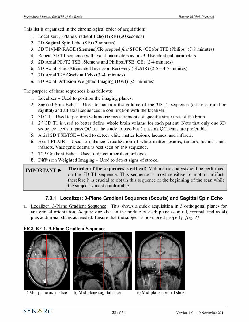
a. Localizer: 3-Plane Gradient Sequence: This shows a quick acquisition in 3 orthogonal planes for
anatomical orientation. Acquire one slice in the middle of each plane (sagittal, coronal, and axial)
plus additional slices as needed. Ensure that the subject is positioned properly. [fig. 1]
FIGURE 1. 3-Plane Gradient Sequence
a) Mid-plane axial slice b) Mid-plane sagittal slice c) Mid-plane coronal slice

Procedure Manual for MRI of the Brain Baxter 161003 Protocol
24 of 54 Version 1.0 – 10 November 2011
b. Sagittal Spin Echo: This scan should consist of
approximately 22 slices to cover the midsection of
the brain as well as the Left and Right medial
temporal lobes. Use the axial slice from the tri-
planar scout to position stack in the middle of
head. See Figure 2.
7.3.2 3D T1 / MP-RAGE / IR-prepped fast SPRR / TFE
a. Orientation: For all GE scanners, use the orthogonal Coronal plane.
FIGURE 3. 3D T1 Coronal orientation and positioning
b. Positioning: The positioning is best done on the mid-sagittal slice (see above). The whole head
(including the top part of the cranium) should be included in the volume box. The entire brain plus
the skull must be included in the slice direction. Check that if the nose is outside the volume that it
will not fold into the region of the brain. DO NOT use foldover suppression techniques in the slice
direction.
FIGURE 2. Placement of slices
for Sagittal Spin Echo

Procedure Manual for MRI of the Brain Baxter 161003 Protocol
25 of 54 Version 1.0 – 10 November 2011
c. Orientation: For Philips Intera and Achieva scanners, Siemens Symphony, Espree and Avanto: use
the orthogonal Sagittal plane.
FIGURE 4. 3D T1 sagittal orientation and positioning
d. Positioning: Use an axial slice that shows the inferior part of the brain and nose as well as mid-
sagittal slice to fully define the volume of the 3D acquisition. Leave approximately 10-15 mm from
top of the head to the top of the FOV. For an external landmark, use the eyes and for an internal
landmark, use the thalamus to position the middle of the volume. For follow up scans, refer to the
screening for positioning. Consistent positioning is critical to the volumetric analysis of this
longitudinal study. Scans that do not contain the whole brain cannot be processed.
► For coronal images, if the acquisition box does not extend past the ears, increase Phase FOV to
100%. If the acquisition box does not cover the head from front to back, add slices if possible. If
not, make sure the nose will not wrap (alias) into the brain.
► For sagittal images, if the acquisition box does not completely encompass the head from front to
back, make sure the posterior brain is included. If the nose extents outside the FOV, it will wrap
into the back of the image. Make sure that this does not impinge on the brain.
► If the subject’s head is larger than the field of view (FOV), a small amount of oversampling (20%)
can be added to eliminate any aliasing. If partial oversampling is not available, the FOV may be
increased to a maximum of 250 mm (this change should be noted on the Transmittal Form and
must be utilized for all follow up scans for that subject). ONLY use this option if Phase FOV is
already at 100% and as a last resort.
IMPORTANT ► Any deviations from the 3D T1 protocol should be:
1. Documented locally;
2. Reported to Synarc;
3. Implemented identically for every subsequent scan for the subject.

Procedure Manual for MRI of the Brain Baxter 161003 Protocol
26 of 54 Version 1.0 – 10 November 2011
e. Read and Phase Directions: The read direction (in blue) must be along the superior-inferior plane
to avoid aliasing of neck and shoulder into the FOV. The phase direction for sagittal (in solid red)
should be anterior-posterior; the phase encoding direction for the coronal in dashed red) should be
left-right.
f. 3D Partition:
For GE Excite and MR450 scanners, use approximately 184 slices with 1.2 mm slice thickness. For
a larger head, you may add slices to get complete coverage; remember that 4 slices are not
reconstructed and also that there is some aliasing of the volume so be sure to cover the head
completely. Remember, however, adding slices adds scan time.
For all Siemens scanners use 176 slices with a slice thickness of 1.2 mm. For Philips scanners use
170 slices with a slice thickness 1.2 mm to fully cover the head from left to right. Do not worry that
the area covered by the slices extends outside the head. Using a Phase FOV less than 100% will
most likely not be an option because of aliasing in the AP direction. If the head is very large, you
may add 20% oversampling to avoid serous aliasing of the face/nose into the brain. Note this
modification on the Transmittal Form. Do NOT change the number of slices as this will affect
contrast.
IMPORTANT ► If any motion artifact is detected, the 3D T1 should be repeated before
proceeding with additional sequences. It is highly recommended to reformat
the coronal images into the axial and sagittal planes or sagittal into axial and
coronal planes to confirm there is no:
• Aliasing (see section 8.5)
• Image shading (see section 8.7.2)
7.3.3 Acquire a Second 3D T1 Sequence
In order to improve the accuracy of the volumetric analysis and to reduce the numbers of repeat
requests for motion, each site is to run a second 3D T1 sequence, identical to the one described above
(see also Appendix I or the QRG). To ensure that the patient is properly positioned for this second
scan, use the vendor specific method to copy the graphics of the previous 3D scan.
Inferior
Posterior
Right
Anterior (Phase encode Sagittal)
Superior (Read Direction)
Left (Phase encode Coronal)

Procedure Manual for MRI of the Brain Baxter 161003 Protocol
27 of 54 Version 1.0 – 10 November 2011
FIGURE 5. Orientation of Axial Turbo
Spin Echo/Fast Spin Echo
It is best to have two acceptable 3D sequences, and you may repeat the second scan if there are
noticeable motion artifacts, if time is available and the patient is cooperative but only one 3D T1 scan
passing QC is needed to have a passing exam for each visit.
7.3.4 Axial 2D PD/T2 Turbo Spin Echo (TSE) / Fast Spin Echo (FSE)
a. Orientation: Angulate Axial Dual Echo TSE/FSE parallel to anterior commissure and posterior
commissure (AC-PC) line. [fig. 5]
b. Positioning: Position on mid-sagittal slice. Be sure to obtain coverage of the entire brain by
including one slice of air above the skull. The acquisition stack should be placed at the most
superior point of the brain, and fully cover the cerebellum as well as all the brain in the lateral and
the anterior-posterior planes. If extra axial slices are required to achieve this coverage, please
acquire those slices. [fig. 6]
NOTE: Acquisition stack for PD/T2 sequence must fully cover the subject’s brain. The flow
saturation band should be placed approximately 15 mm below acquisition stack.
c. Slices: 48 to 50, 3-mm, slices covering the entire brain, with no gap between slices, interleaved
acquisition. If necessary, add 2-4 additional slices in order to obtain full brain coverage. This may
require an increase of the repetition time (TR), which will result in an increase of total acquisition
time. Please be sure to avoid altering additional parameters. You may optimize the TR time
(maintaining 2 groups of concatenations) to minimize scan time.
d. Flow Saturation Band: 50-mm flow saturation band inferior to the MRI slices and positioned about
15-mm from the bottom of the MRI stack to reduce inflow effects.
e. Fat Saturation to be turned on (Vendor specific terms include Fat Sat and SPIR)
FIGURE 6. Axial 2D TSE/FSE Stack
Placement

Procedure Manual for MRI of the Brain Baxter 161003 Protocol
28 of 54 Version 1.0 – 10 November 2011
f. Parallel imaging is allowed for scanners with phased array coils: for GE this means ASSET, for
Philips this means SENSE and for Siemens, iPAT may be turned on. Factors from 1.5 to 2 are
allowed.
7.3.5 Axial 2D FLAIR / T2* Gradient Echo / Diffusion Weighted Imaging (DWI)
Please refer to the protocols found in Appendix I ‘Technical Parameters for MRI of the Brain’ for
direction on how to acquire these sequences. Synarc should be notified if your facility will not be able
to follow the parameters listed but other than the 3D T1 sequence, many of the values are only
approximate and may vary for your specific scanner. Please note that the FLAIR must have dark CSF
to allow white matter lesions to be highlighted.
Note that the FLAIR, T2* and DWI orientation can be copied from the Dual echo sequence.
For scanners with phased array coils, it is allowable to use factor of 1.5 to 2 parallel imaging for the the
FLAIR, T2* and the DWI sequence.
8.0 COMMON PROBLEMS SEEN WITH SUBJECT MRI SCANS
Due to the nature of the disease, it may be challenging for the subject to properly complete the entire
MRI exam. In order to get a good measure of brain volume, the imaging protocol is designed to give as
clear a boundary between brain and CSF as possible. Anything that alters this (movement,
inhomogeneity, chemical shift) potentially compromises such measures. It is highly recommended
that the raw and reformatted images are viewed after each acquisition to determine whether
quality is sufficient for submission. If problems are detected, the scan should be repeated while the subject is at the MRI facility. The following sections illustrate examples of common problems
that can be encountered while acquiring MRI images and possible solution.
8.1 Incorrect Orientation / Image Plane Misalignment
In this example, the 3D coronal T1 sequence was acquired with
angulation. Note that the 3D T1 sequences are to use orthogonal
orientation (i.e. no angulation).
Possible Remedies:
• Check that orthogonal plane was used.
• If subject moved significantly, reposition subject and
reacquire ALL scans.
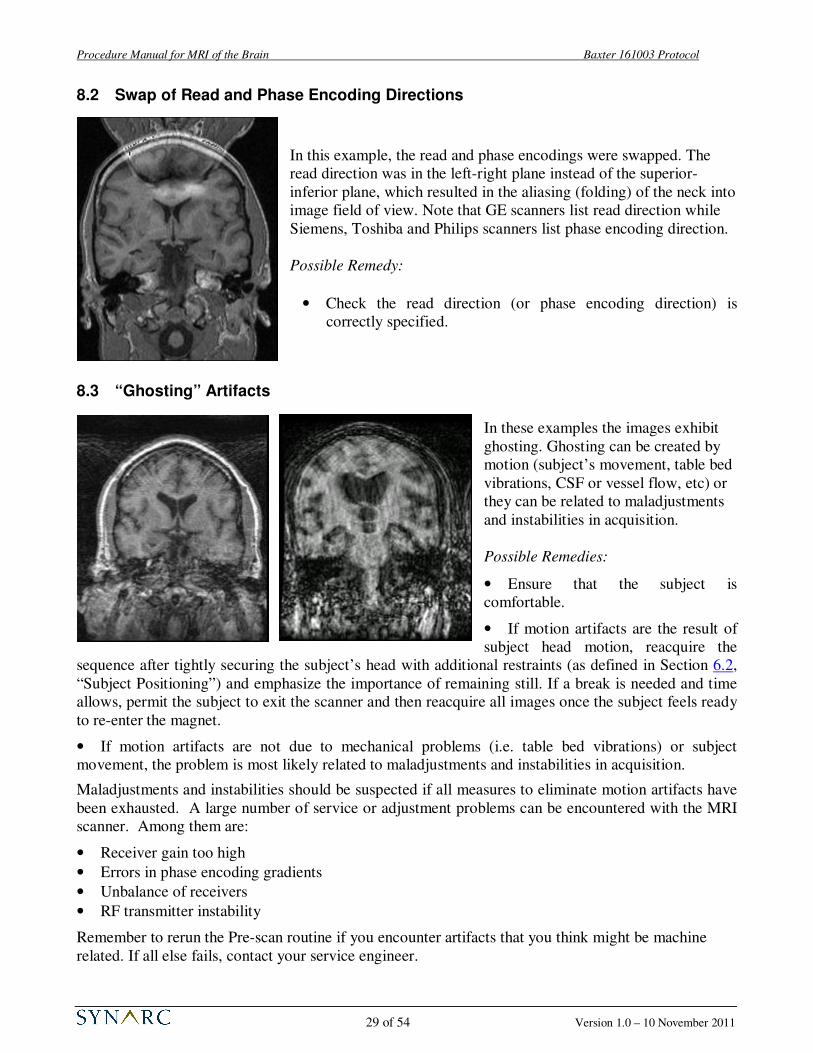
Procedure Manual for MRI of the Brain Baxter 161003 Protocol
29 of 54 Version 1.0 – 10 November 2011
8.2 Swap of Read and Phase Encoding Directions
In this example, the read and phase encodings were swapped. The
read direction was in the left-right plane instead of the superior-
inferior plane, which resulted in the aliasing (folding) of the neck into
image field of view. Note that GE scanners list read direction while
Siemens, Toshiba and Philips scanners list phase encoding direction.
Possible Remedy:
• Check the read direction (or phase encoding direction) is
correctly specified.
8.3 “Ghosting” Artifacts
In these examples the images exhibit
ghosting. Ghosting can be created by
motion (subject’s movement, table bed
vibrations, CSF or vessel flow, etc) or
they can be related to maladjustments
and instabilities in acquisition.
Possible Remedies:
• Ensure that the subject is
comfortable.
• If motion artifacts are the result of
subject head motion, reacquire the
sequence after tightly securing the subject’s head with additional restraints (as defined in Section 6.2,
“Subject Positioning”) and emphasize the importance of remaining still. If a break is needed and time
allows, permit the subject to exit the scanner and then reacquire all images once the subject feels ready
to re-enter the magnet.
• If motion artifacts are not due to mechanical problems (i.e. table bed vibrations) or subject
movement, the problem is most likely related to maladjustments and instabilities in acquisition.
Maladjustments and instabilities should be suspected if all measures to eliminate motion artifacts have
been exhausted. A large number of service or adjustment problems can be encountered with the MRI
scanner. Among them are:
• Receiver gain too high
• Errors in phase encoding gradients
• Unbalance of receivers
• RF transmitter instability
Remember to rerun the Pre-scan routine if you encounter artifacts that you think might be machine
related. If all else fails, contact your service engineer.

Procedure Manual for MRI of the Brain Baxter 161003 Protocol
30 of 54 Version 1.0 – 10 November 2011
8.4 Flow Compensation
In the T2-weighted image shown to the right, the flow
compensation was not applied during acquisition resulting in
artifacts from cerebrospinal fluid (CSF) motion running
through the anatomy of the brain. The artifacts running through
the eyes come from the eyes motion and cannot be avoided, but
they do not have any influence on brain anatomy depiction.
Possible Remedies:
• Use flow compensation
8.5 Aliasing (Folding) in 3D T1
These images show aliasing in the coronal images. Foldover generally occurs when the subject’s head
size is larger than the acquisition box.
Possible Remedies:
• If the acquisition box does not fully cover the subject’s head, increase the Phase FOV up to 100%.
• For Siemens and Philips scanner, you may use 20% oversampling to eliminate this foldover.
• If you cannot use 20% oversampling you may increase your FOV to 250 mm (notify Synarc) but
this cannot be done on follow ups only on a screening scan.
• If the foldover is in the slice direction, adding more slices (if possible) or repositioning the head
within the volume are the only options.

Procedure Manual for MRI of the Brain Baxter 161003 Protocol
31 of 54 Version 1.0 – 10 November 2011
8.6 Poor Signal-to-Noise Ratio (SNR) and Contrast-to-Noise Ratio (CNR)
Below are two examples showing good SNR (a) and poor SNR (b).
(a) Good SNR (b) Poor SNR (c) Poor CNR
Another example of poor contrast-to-noise (CNR) is shown in example (c) where the contrast between
the gray and white matter is indistinguishable. In addition, the image is grainy and has an overall low
signal.
Possible Remedies for poor SNR and CNR:
• Check to ensure that the appropriate head coil was used (do NOT change coils from subject’s baseline to follow up)
• Ensure that the head coil is properly connected.
• Check that the flip angle value corresponds to the protocol (see Appendix I, “Technical Parameters for MRI of the Brain”).
• Check time parameters: repetition time (TR), inversion time (TI), and echo time (TE).
• Check the receiver gain. The gain may be too low (insufficient amplification). Rerun the Pre-scan
routine in manual or automatic mode.
8.7 Signal Loss
8.7.1 Inferior Slices
In this example, there was a signal drop at the
lower part of the brain. This is usually due to
improper positioning of the subject’s head, an
incorrectly tuned RF coil or an improper or bad
connection.

Procedure Manual for MRI of the Brain Baxter 161003 Protocol
32 of 54 Version 1.0 – 10 November 2011
Possible Remedies:
• Ensure that the subject is positioned correctly in the head coil. Rerun the localizer, 3-plane
scout and verify that the prescription of the mid-plane sagittal slice is centered at the thalamus.
Reposition subject’s head if necessary and rescan.
• Check that the RF coil is properly connected. (This may require that you enter the magnet room
and check a cable).
8.7.2 Inhomogeneity or Shading Artifact
Here is an image from an axial reformat of the off-coronal 3D T1 acquisition:
The images are from the same slice with two different window/level settings. It is apparent that the
signal is stronger on the posterior portion of the head.
Possible Remedies:
• Ensure volumetric radio frequency (RF) head coil is used. Surface coils are not permitted.
• If a phased array coil was used, the proper vendor specific homogeneity filter must be used
(PURE for GE, CLEAR for Philips and Pre-scan Normalization for Siemens). DO NOT use
phased array coils without these filters.
• Ensure that the subject is positioned correctly in the head coil. Rerun the localizer, 3-plane
scout and verify that the prescription of the mid-plane sagittal slice is centered at the thalamus.
Reposition subject’s head if necessary and rescan.
• Rerun automatic or manual pre-scan.
• Investigate with your field engineer whether the coil or receiver gain needs service.
8.8 Metal Artifact
Magnetic field distortions: In this example there is blacking out due to the presence of metal near the
participant’s head.

Procedure Manual for MRI of the Brain Baxter 161003 Protocol
33 of 54 Version 1.0 – 10 November 2011
(d) Adequate head coverage
Possible Remedy:
• Make sure the participant is not wearing any metal. Check for hair clips, metallic makeup
(i.e. permanent eyeliner), necklace, safety pins, removable dentures and bridges, and facial
jewelry. Remove metal and rescan. Certain mascara and tattoos will also cause artifacts.
• If the metal cannot be removed and the artifacts hinder anatomical depiction of the brain,
the subject may have to be excluded.
NOTE: After repositioning subject, rerun the Pre-scan routine before re-scanning.
8.9 Inadequate Head Coverage
In the figure above, images (a) and (b) illustrate examples of inadequate head coverage. Images (c) and
(d) exemplify adequate head coverage. Please make certain that the field of view is large enough to
include the whole head in the image. Ideally there should be air visible posteriorly, laterally, and
superiorly beyond the full extent of the scalp. In the anterior portion of the brain, please ensure that the
full extent of the brain and CSF are visible. Centering the subject in both the center of the RF coil and
FOV is critical.
(b) Image is inadequate inferiorly
(c) Adequate head coverage
(a) Image is cut too close superiorly

Procedure Manual for MRI of the Brain Baxter 161003 Protocol
34 of 54 Version 1.0 – 10 November 2011
9.0 Data Archive onto Digital Media
At the end of the exam, export images to digital media (CD) in uncompressed DICOM format. Data
submissions using CD or Synarc’s Synarc Connect (FTP) website are preferable. Images should be
submitted to SYNARC within 24 hours of acquisition (as defined in Section 10.0, “Data Submission
Procedures”). In addition to archiving the data to digital media, the MRI facility will need to locally
archive this data.
Questions about correct data archive should be addressed to:
BAXTER 161003 Study Team (BAXTER2207).
Synarc Inc.
7707 Gateway Blvd, 3rd
Floor
Newark, CA 94560
United States of America
Tel: 415-817-8900
Fax: 415-817-8999
Email : [email protected]
10.0 Data Submission Procedures
MRI images should be submitted to Synarc within 24 hours of acquisition according to the
procedures described in this section. Synarc is providing two methods for data submission: via courier
or FTP website (section 10.4, “Submitting Data via Synarc’s FTP Website”).
10.1 Submitting MRI Data Archived on Digital Media
If submitting images on digital media, export the data to a CD in uncompressed DICOM format. Use
one CD per exam.
CD: Use a black permanent marker to label the CD with:
• Sponsor name (Baxter)
• Study protocol number (161003)
• Site Number (2 digits)
• Subject Number (4 digits)
• Subject Year of Birth (or Phantom Serial Number J####)
• Exam date in alphanumeric format (i.e. 05-Dec-2011)
A list of correct abbreviations for the months used in date
fields on the Transmittal Forms is given below:
January JAN July JUL
February FEB August AUG
March MAR September SEP
April APR October OCT
May MAY November NOV
June JUN December DEC
• Visit (Phantom Scan, Baseline, 9-Month, 18-Month, Unscheduled or Early
Termination)
Baxter
Protocol 161003
Site 01, Pat #1234
YOB : YYYY
05-Dec-2011
Baseline

Procedure Manual for MRI of the Brain Baxter 161003 Protocol
35 of 54 Version 1.0 – 10 November 2011
10.2 Data Preparation
When preparing to send the archived MRI exam data on electronic media complete and include the
Transmittal Form. The clinical site should retain the pink copy and send the remaining pages (white
and yellow) to Synarc (as defined in Appendix III, “Instructions for Completing the Transmittal Form
for MRI of the Brain” along with the electronic media containing the exam data.
IMPORTANT ►
►
►
Transmittal Form white and yellow copies to be sent to Synarc via courier with
the MRI images. There is no need to send the white and yellow copies of the
Transmittal Form if submitting data via Synarc Connect (FTP) website.
Transmittal Form pink copy to be kept at site in study records.
Please make sure to use the appropriate Transmittal Form (subject or phantom).
10.3 Data Preparation
FedEx is the designated courier for this study. The FedEx account number which may be used for the
161003 study is 244070876. Preprinted air waybills (AWBs) will be provided.
Complete the sender sections of the pre-printed airway bill, keeping a copy for tracking purposes.
Place the MRI Transmittal Form and labeled media for each subject into a shipping envelope (NOT
with the AWB).
Contact your local FedEx to schedule your package pick-up taking into account the latest call and pick-
up time.
10.4 Submitting Data via Synarc’s FTP Website (SynarcConnect.com)
Synarc will provide a secure website as an alternative data transmission method to those facilities that
have the capability of transmitting MRI images via the internet.
For facilities that have indicated interest in using SynarConnect on the Pre-Trial Questionnaire, Synarc
will setup a personal login name and password for each MRI technologist who is able to use the
website.
To transmit subject or phantom images using Synarc’s FTP website:
1. Fill in the electronic version of the Transmittal form. Print a copy for your records.
2. Upload the images to Synarc’s website.
3. Keep the original transmittal form at the site.

Procedure Manual for MRI of the Brain Baxter 161003 Protocol
36 of 54 Version 1.0 – 10 November 2011
11.0 Supplies Provided By Synarc
Synarc will be providing the following supplies to the Clinical Site and the MRI Facility:
• Procedure Manual for MRI of the Brain
• Transmittal Forms for Subject MRI Scans
• Transmittal Forms for Phantom MRI Scans
• Quick Reference Guide for Acquiring MRI of the Brain
• Pre-printed airway bills
• ACR Phantom, if necessary
After receipt of a Pre-Trial Questionnaire that meets Synarc’s preliminary site requirements and
acceptance of a training date, copies of the “Procedure Manual for MRI of the Brain” and the rest of
the supplies listed above will be provided.
To request more study supplies, fill out the Supply Order Form found in Appendix VI, “MRI Study
Supply Order Form” and fax to 415-817-8999. Please submit supply requests at least 2 weeks prior
to running out of supplies in order to allow time for delivery.

Procedure Manual for MRI of the Brain Baxter 161003 Protocol
37 of 54 Version 1.0 – 10 November 2011
APPENDIX I: Technical Parameters for MRI of the Brain
The MRI techniques described below will not change for the entire study and will be standardized
between study sites. A short-acting sedative may be used in selected patients to improve compliance and
reduce movement artifacts; this decision should be made by the physician at each site and no efficacy
assessment should take place less than 72 hours after the sedative is given. Patients who are unable to
maintain a fixed head position in the scanner at their first scan will be excluded from the study.
Standardization may result in small variations of the parameters listed below. Should the need to
optimize parameters for your particular scanner arise, Synarc will work with your facility as required.
This appendix is divided up by vendor and scanner type. There are three 1.5T scanner types listed; GE
Excite Release 11+ and Optima MR450w; Siemens Symphony, Espree, Avanto and Aera; and Philips
Achieve, Intera and Ingenia scanners.
Choose the table that is related to your scanner. Note: due to some hardware differences with each
group, there may be some slight variations in the output parameters that are calculated by the scanner.
For sequences other than the 3D T1, you may need to slightly modify TR times to get the desired
number of slices. Note also that TE times for FSE or TSE scans are approximate only and the actual
value of the TE’s are related to the echo spacing times.
Please see the tables on the following pages.

Procedure Manual for MRI of the Brain Baxter 161003 Protocol
38 of 54 Version 1.0 – 10 November 2011
GE 1.5T Signa Excite (Release 11+) and MR450: Parameters for MRI of the Brain
Sequences to be scanned in exact order:
1. 3 Plane Scout
2. 2D Sagittal T1 SE
3. Asset Calibration (for Release 12 and above; not needed for Release 11)
4. 3D Coronal IR-prepped fast SPGR
5. 3D coronal IR-prepped fast SPGR (2nd
scan is repeat of first with exact graphics)
6. 2D Axial PD/T2 FSE
7. 2D Axial T2 Flair
8. 2D Axial T2* GRE
9. 2D Axial DWI
Note that the 8 channel Head coil may only be used with Excite Release 12 and above and all MR450
releases. Sites at Release 11 WHICH DO HAVE PURE may also use the 8 channel head coil (but must
explicity state this on questionnaire and on the transmittal forms. This filter is used to reduce the
inhomogeneity introduced by the multi-channel coil. DO NOT USE the SCIC filter.
For Release 11 scanners, the Birdcage Head coil must be used (unless you have the PURE filter – see
above). Asset Cal scan is not needed.
If the scanner is upgraded from Release 11 to Release 12 or higher during the course of the study, you
MUST stay with the Birdcage Head coil if you started with it.
Please see the table on the following page.

Procedure Manual for MRI of the Brain Baxter 161003 Protocol
39 of 54 Version 1.0 – 10 November 2011
GE 1.5T Signa Excite Release 11+ and MR450: The table below summarizes the relevant
parameters to be used for each subject.
PROTOCOL FOR MRI OF THE BRAIN
GE 1.5T Signa Excite (Release 11+) and MR450
Sequence #
1 2 3 4&5 6 7 8 9
3 Plane
Localizer
2D Sag SE
Asset Calibration
3D Coronal T1
Axial DE PD/T2
Axial T2 Flair
Axial T2* GRE
Axial DWI
Subject position
Coil (Rel 12+) 8HRBrain 8HRBrain 8HRBrain 8HRBrain 8HRBrain 8HRBrain 8HRBrain 8HRBrain
Coil (Rel 11) Head Head Head Head Head Head Head
Imaging parameters
Plane 3 Plane Sagittal Axial Coronal Oblique Oblique Oblique Oblique
mode 2D 2D 3D 2D 2D 2D 2D
pulse sequence GRE SE fast SPGR FSE T2Flair GRE DW/EPI
Grad Mode (twinspeed only)
Zoom Zoom Zoom Zoom Zoom Zoom Zoom
Imaging options fast, VB, EDR, IR
prep FC FC epi, diff
Scan Timing
# shots/echoes 1 1 1 2 1 1 1
TE [ms] 1.3 Min Full
(14)
Min Full (4.2)
~20, 120 120 30 shortest
(81+)
TR [ms] 4.8 600 9.4 4000+ 9000 550 11000
TI [ms] 450 2200
flip angle 15 20
ETL ~12
Bandwidth [kHz] 31.2 15.6 13.89 15.6 15.6 12.5 250
Acquisition timing
Frequency 256 256 192 256 256 256 128
Phase 128 192 192 192 160 160 128
NEX 1 0.75 1 1 1 1 1
Phase FOV 1 1 0.85 0.75 1 1 1
Freq Dir SI SI AP AP AP LR
Scanning range
FOV 260-280 260 280 240 260 240 240 240
slice thickness 5 4 1.2 3 5 5 5
Spacing (2D) 5 1 0 1 1 1
Locs per slab (3D)
184
Additional menus
Sat Fat Sat, Sat
(I) Sat (I)
User CV Turbo
mode 1 Min Acq 2
Ramp Samp 1
Image Enhance PURE (w/
8HRBrain) PURE PURE PURE
DWI b=1000,
ALL,
Opt TE,
DSE
Additional instructions
No
ZIP512
Needed for PURE and
ASSET No ZIP2
ASSET allowed
ASSET allowed
ASSET allowed
ASSET allowed
Scan info
imaging time 0:21 1:41 0:20 7:35 1.5 – 4 2.5 – 4 2.5 – 4 0:44
approx slices 7 x 3 22 Cover
entire brain 180 50 x 2 25 25 40 (20x2)

Procedure Manual for MRI of the Brain Baxter 161003 Protocol
40 of 54 Version 1.0 – 10 November 2011
Siemens 1.5T Magnetom Symphony (Sonata), Espree, Avanto and Aera: Parameters for MRI of the Brain
Sequences to be scanned in exact order:
1. 3 Plane Scout
2. 2D Sagittal T1 SE
3. 3D Sagittal MPRAGE
4. 3D Sagittal MPRAGE (2nd
scan is repeat of first with exact graphics)
5. 2D Axial PD/T2 FSE
6. 2D Axial T2 Flair
7. 2D Axial T2* GRE
8. 2D Axial DWI
Note that only TIM scanners may use multi-channel coils and you must use the Prescan Normalization
filter to reduce RF inhomogeneities. If your scanner is upgraded from non-TIM to TIM during the
course of the study, you may not use multi-channel coils but must use the same head coil as before.
Note also that Symphony TIM scanner do not have Prescan Normalization and may not use the TIM
head coil but must use the CP head coil.
Please see the table on the following page.

Procedure Manual for MRI of the Brain Baxter 161003 Protocol
41 of 54 Version 1.0 – 10 November 2011
Siemens 1.5T Magnetom Symphony, Espree, Avanto and Aera: The table below
summarizes the relevant parameters to be used for each subject.
PROTOCOL FOR MRI OF THE BRAIN
Siemens 1.5T Symphony, Espree, Avanto and Aera
Sequence # 1 2 3 & 4 5 6 7 8
Sequence NAME 3 plane loc Sag SE 3D MPRAGE Ax DE TSE Ax Flair Axial T2* Axial DWI
2D GRE 2D SE *fl3d1_ns 2D TSE 2D TIR 2D GRE 2D EPI
Orientation Sagittal Sagittal Axial Axial Axial Axial
Phase enc direction
A >> P A >> P R >> L R >> L R >> L A>>P
Phase oversampling [%]
0 0 0 0 0 0
Slice oversampling [%]
No
Slices per group/slab
3 x 9 22 176 ~50 25 25 20
FOV read [mm] 280 260 240 260 240 240 240
FOV phase [%] 100 100 100 75 100 100 100
Slice thickness [mm]
8 4 1.2 3 5 5 5
Distance factor [%]
100 25 - 0 20 20 30
TR [ms] 20 500-600 2400 >4000 10000 (with 2
concatenations) ~420 5100
TE [ms] 5 14 ~3.6 ~20, 120 120 29 137
Measurements 1 1 1 1 1 1 1
Coil elements Body
Multichannel coil with TIM or Head coil without TIM
Multichannel coil with TIM or Head coil without TIM
Multichannel coil with TIM or Head coil without TIM
Multichannel coil with TIM or
Head coil without TIM
Multichannel coil with TIM or
Head coil without TIM
Multichannel coil with TIM or Head coil without TIM
Mag preparation Non-Sel IR IR
TI [ms] 1000 2500
Flip Angle 40 8 20
Fat supp None None None Yes None None
Base resolution 192 256 192 256 256 256 128
Phase resolution 75 75 100 75 75 63 78
Slice resolution 100
Phase partial Fourier
Off 3/4 Off Off Off Off Off
Slice partial Fourier
Off
Filter None None Prescan Norm Prescan Norm Prescan Norm Prescan Norm None
Interpolation Off No No No No No No
iPAT None No No Yes Yes Yes Yes
Bandwidth [Hz/px] 180 130 180 130 130 130
Flow comp No No No Yes - slice Yes - slice No No
Assymetric echo Off Off Off Off Off Off
etl ~8 – 16 ~12 - 20
Gradient mode Fast Fast Fast Fast Fast
Excitation Non-select
RF spoiling On On On
b - value 1000
Approximate scan time [min:sec]
1:45 8:00 2.5 – 4.5 2.5 – 4 2.5 – 4.5 0:40

Procedure Manual for MRI of the Brain Baxter 161003 Protocol
42 of 54 Version 1.0 – 10 November 2011
Philips 1.5T Gyroscan Achieva, Intera and Ingenia: Parameters for MRI of the Brain
Sequences to be scanned in exact order:
1. 3 Plane Scout
2. 2D Sagittal T1 SE
3. 3D Sagittal TFE
4. 3D Sagittal TFE (2nd
scan is repeat of first with exact graphics)
5. 2D Axial PD/T2 TSE
6. 2D Axial T2 Flair
7. 2D Axial T2* FFE
8. 2D Axial DWI
Note: If a SENSE-head coil is used, you must use CLEAR to reduce RF inhomogeneities. If you start
the study with a regular Head coil, you may not switch to a SENSE coil during the study. Further, if
you start with a particular SENSE coil, you may not switch coils during the study, even if the site
acquires a SENSE coil with more elements.
Please see the table on the following page.

Procedure Manual for MRI of the Brain Baxter 161003 Protocol
43 of 54 Version 1.0 – 10 November 2011
Philips 1.5T Gyroscan Achieva, Intera and Ingenia: The table below summarizes the relevant
parameters to be used for each subject.
PROTOCOL FOR MRI OF THE BRAIN Philips 1.5T Gyroscan Achieva, Intera and Ingenia
Sequence # 1 2 3 & 4 5 6 7 8
3Plane
Localizer 2D Sagittal 3D Sagittal T1 Axial PD/T2
Axial T2 Flair
Axial T2* FFE
Axial DWI
Coil Selection SENSE-head
or Head must keep
same RF coil for entire study
CLEAR Yes Yes Yes Yes
FOV (mm) 260-280 260 240 260 240 240 240
RFOV(%) 100 100 75 100 100 100
Foldover suppression No No No No No No
Matrix scan 256 256 192 256 256 256 128
Reconstruction 256 256 256 256 256 256 128
Scan Percentage (%) 50 75 100 75 62.5 62.5 100
SENSE No No No Yes Yes Yes Yes
Slices 7 x 3 22 170 50 25 25 20
slice thickness (mm) 5 4 1.2 3 5 5 5
Slice gap (mm) 5 1 Overcontiguous
No 0 1 1 1.5
slice orientation Sagittal Sagittal Axial Axial Axial Axial
Foldover direction AP AP LR LR LR AP
fat shift direction F
Rest slabs 0 0 0 0 Inferior
Scan mode MS MS 3D MS MS MS MS
technique FFE SE FFE SE IR FFE EPI
Contrast enhancement
T1
Fast Imaging mode TFE TSE TSE EPI
shot mode multi-shot
TFE/TSE factor 192 8 - 16 12-20
shot Interval (ms) 2155
profile order linear default default default Default
Echoes 1 1 2 1 1 1
partial echo No no No No No
TE (ms) 9 4 ~20, 120 120 30
Flip angle (deg) 8 20
TR 600 shortest (8.6) >4000 10000 ( with 2 packages)
550 Shortest
Half Scan 0.75 No No No No No
Water fat shift ~1.8 ~1.3 ~1.8 ~1.8 ~2.2 Maximum
SPIR No No Yes No No
TFE / IR prepulse invert Invert
slice selection No Yes
TI (ms) 1000 2500
Flow compensation No No Yes Yes No No
NSA 1 1 1 1 1 1 1
Voxel FH AP LR
1.02 1.36
4
1.25 1.25 1.2
3 1.02 1.36
5 0.94 1.5
5 0.94 1.5
b=0 & b=1000
Approximate scan time
0:20 1:45 7:45 2.5 – 4.5 2-4 2.5 – 4.5 0:45

Procedure Manual for MRI of the Brain Baxter 161003 Protocol
44 of 54 Version 1.0 – 10 November 2011
APPENDIX II: Technical Parameters for ACR Phantom Scans
(Please see following pages)

Procedure Manual for MRI of the Brain Baxter 161003 Protocol
45 of 54 Version 1.0 – 10 November 2011
GE 1.5T Signa Excite (Release 11 – 15) and MR450: Scanning Protocol for ACR Phantom Scan
Sites with GE 1.5T Signa Excite or Optima MR450w scanners use the following set of protocols to scan the
ACR phantom.
Sites using Release 11 software must use the Birdcage Head coil.
If you use the 8 channel GE head coil (known as 8HRBrain), position the phantom as far into the coil
as possible. You will also need to run the Asset Cal and use the PURE filter on the images to avoid the
inhomogeneity of the coils affecting the measurements. If you cannot get the ACR phantom in this
coil, you may use the Birdcage coil for the phantom and the 8 channel head coil for subjects.
Note: If you have Twinspeed gradients, use the Zoom mode to get the proper TE and TR times for the
3D sequence.
Sequence # 1 2 3 4 5
Protocol 3 Plane
Localizer 2D Sagittal
Locator Asset Cal 2D Axial SE 3D Coronal T1
Patient positon RF Coil 8HRBrain or Head 8HRBrain or Head
8HRBrain only (Release 12 +)
8HRBrain or Head 8HRBrain or Head
Plane 3 Plane Sagittal Axial Coronal
Imaging parameters
mode 2D 2D 2D 3D
pulse sequence GRE SE SE fast SPGR
Grad Mode (for twinspeed only)
Zoom Zoom Zoom Zoom
Imaging options fast, VB, EDR, IR
Scan Timing
TE 1.3 20 20 Min Full (4.2)
TR 4.8 250 500 9.4
Inv time 450
flip angle 15
Bandwidth 31.2 15.6 15.6 13.89
Frequency 256 256 256 192
Acquisition timing
Phase 128 256 256 192
NEX 1 1 1 1
Phase Fov 1 1 1 0.85
Freq Dir SI AP SI
FOV 260-280 250 250 240
Scanning range
slice thickness 5 20 5 1.2
Spacing (2D) 5 0 5
Locs per slab (3D) 184
Additional menus User CV Turbo mode 1
Image Enhance PURE PURE
Additional instructions
No ZIP512 No ZIP2
Scan info imaging time :21 1:04 2:08 7:12
approx slices 7 x 3 1 enough to cover 11 180
Additional instructions
8HRBrain coil can only be used with Release 12 and above. PURE must be used but ASSET must not be used!

Procedure Manual for MRI of the Brain Baxter 161003 Protocol
46 of 54 Version 1.0 – 10 November 2011
Page 2 of QRG for Phantom for Pre-Qualification Scans
Sequence
# 6 7 8 9
Axial DE PD/T2
Axial T2 Flair
Axial T2* GRE
Axial DWI
Subject position
Coil (Rel 12+) 8HRBrain 8HRBrain 8HRBrain 8HRBrain
Coil (Rel 11) Head Head Head Head
Imaging parameters
Plane Oblique Oblique Oblique Oblique
mode 2D 2D 2D 2D
pulse sequence FSE T2Flair GRE DW/EPI
Grad Mode (twinspeed only)
Zoom Zoom Zoom Zoom
Imaging options FC FC epi, diff
Scan Timing
# shots/echoes 2 1 1 1
TE [ms] ~20, 120 120 30 shortest
(81+)
TR [ms] 4000+ 9000 550 11000
TI [ms] 2200
flip angle 20
ETL ~12
Bandwidth [kHz] 15.6 15.6 12.5 250
Acquisition timing
Frequency 256 256 256 128
Phase 192 160 160 128
NEX 1 1 1 1
Phase FOV 0.75 1 1 1
Freq Dir AP AP AP LR
Scanning range
FOV 260 240 240 240
slice thickness 3 5 5 5
Spacing (2D) 0 1 1 1
Locs per slab (3D)
Additional menus
Sat Fat Sat, Sat
(I) Sat (I)
User CV Min Acq 2 Ramp
Samp 1
Image Enhance PURE PURE PURE
DWI b=1000,
ALL,
Opt TE,
DSE
Additional instructions
ASSET allowed
ASSET allowed
ASSET allowed
ASSET allowed
Scan info imaging time 1.5 – 4 2.5 – 4 2.5 – 4 0:44
approx slices 50 x 2 25 25 40 (20x2)

Procedure Manual for MRI of the Brain Baxter 161003 Protocol
47 of 54 Version 1.0 – 10 November 2011
Siemens Symphony, Espree, Avanto and Aera: Scanning Protocol for ACR Phantom Scan
Sites with Siemens Symphony, Avanto or Espree should use the following protocols to scan the ACR Phantom.
Sites without TIM should use (for the duration of the study) the conventional quadrature CP Head coil. Sites
with TIM may use the multi-channel coil provided with the scanner. You must use Prescan Normalization. Once
you start with a coil, you may not switch, even if a more advanced coil is available to your site.
Note: the 3D MPRAGE sequence is done in the Sagittal plane.
Sequence # 1 2 3 4
Protocol 3 Plane
Loc 2D Sagittal
Loc 2D Axial SE 3D MPRAGE
Protocol Name *fl3d1_ns
Parameter Card
Routine
Orientation Sagittal Axial Sagittal
Phase enc direction A>>P R>>L A>> P
Phase oversampling [%] 0 0 0
Slice oversampling [%] No
Slices per slab 7 x 3 1 11 176
FOV read [mm] 260-280 250 250 240
FOV phase [%] 100 100 100
Resolution-common Slice thickness [mm] 5 20 5 1.2 mm
Routine
Distance factor [%] 100 100 -
TR [ms] 250 500 2400
TE [ms] 20 20 ~3.6
Measurements 1 1 1 1
Coil elements Multi-channel Multi-Channel multi-channel Multi-channel
Contrast-common
Mag preparation Non-Sel IR
TI [ms] 1000
Flip Angle 8
Fat supp None None None None
Base resolution 256 256 256 192
Phase resolution 50 100 100 100
Slice resolution 100
Phase partial Fourier Off Off Off Off
Slice partial Fourier Off
Resolution-common Filter None None Prescan Norm Prescan Norm
Resolution-common Interpolation No No No No
Contrast-iPAT iPAT No No No No
Sequence-part 1
Bandwidth [Hz/px] 130 130 180
Flow comp No No No No
Assymetric echo Off Off Off Off
Sequence-part 2 RF pulse type Normal Normal Normal
Gradient mode Fast Fast Fast
Approx scan time 0:21 1:04 2:08 8:00

Procedure Manual for MRI of the Brain Baxter 161003 Protocol
48 of 54 Version 1.0 – 10 November 2011
Page 2 of QRG for Phantom for Pre-Qualification Scans
Sequence # 5 6 7 8
Sequence NAME Ax DE TSE Ax Flair Axial T2* Axial DWI
2D TSE 2D TIR 2D GRE 2D EPI
Orientation Axial Axial Axial Axial
Phase enc direction
R >> L R >> L R >> L A>>P
Phase oversampling [%]
0 0 0 0
Slice oversampling [%]
Slices per group/slab
~50 25 25 20
FOV read [mm] 260 240 240 240
FOV phase [%] 75 100 100 100
Slice thickness [mm]
3 5 5 5
Distance factor [%]
0 20 20 30
TR [ms] >4000 10000 (with 2
concatenations) ~420 5100
TE [ms] ~20, 120 120 29 137
Measurements 1 1 1 1
Coil elements
Multichannel coil with TIM or Head coil without TIM
Multichannel coil with TIM or
Head coil without TIM
Multichannel coil with TIM or
Head coil without TIM
Multichannel coil with TIM or Head coil without TIM
Mag preparation IR
TI [ms] 2500
Flip Angle 20
Fat supp Yes None None
Base resolution 256 256 256 128
Phase resolution 75 75 63 78
Slice resolution
Phase partial Fourier
Off Off Off Off
Slice partial Fourier
Filter Prescan Norm Prescan Norm Prescan Norm None
Interpolation No No No No
iPAT Yes Yes Yes Yes
Bandwidth [Hz/px] 130 130 130
Flow comp Yes - slice Yes - slice No No
Assymetric echo Off Off Off
etl ~8 – 16 ~12 - 20
Gradient mode Fast Fast Fast
Excitation
RF spoiling On On
b - value 1000
Approximate scan time [min:sec]
2.5 – 4.5 2.5 – 4 2.5 – 4.5 0:40

Procedure Manual for MRI of the Brain Baxter 161003 Protocol
49 of 54 Version 1.0 – 10 November 2011
Philips Gyroscan Achieva, Intera, and Ingenia: Scanning Protocol for ACR Phantom Scan
Sites with all types of Philips 1.5T Gyroscan scanners use the following protocols to scan the ACR phantom.
Sites without SENSE coil technology must use the quadrature coil for the duration of the study. Sites with SENSE coil technology may use the SENSE coil for the phantom and subject studies. Note that for this study,
the 3D sequence is run in the sagittal direction. Note that if a site starts with a particular SENSE coil, they may
not switch to a version with more elements, even if the site acquires one.
Sequence # 1 2 3 4
Protocol 3 Plane
Localizer 2D Sagittal Localizer
2D Axial SE 3D Sagittal T1
Geometry
Coil Selection Sense-Head Sense-Head Sense-Head
CLEAR- to be used with Sense coils
CLEAR CLEAR
FOV (mm) 260-280 250 250 240
RFOV(%) 100 100 100
Foldover suppression No No No
Matrix scan 256 256 192
Reconstruction 256 256 256
Scan Percentage (%) 100 100 100
SENSE no no No
Slices 7 x 3 1 11 170
slice thickness (mm) 20 5 1.2
slice gap (mm) 0 5 Overcontiguous slices - No
slice orientation Sagittal Axial Sagittal
Foldover direction AP RL AP
fat shift direction F
Contrast
Scan mode 2D MS 3D
technique SE SE FFE
Contrast enhancement T1
Fast Imaging mode TFE
shot mode multi-shot
TFE factor 192
shot interval user defined
(ms) 2155
profile order Linear
Echoes 1 1 1
partial echo No No No
TE User defined User defined user defined
(ms) 20 20 4
Flip angle (deg) 8
TR 250 500 9.5
Half Scan No No No
Water fat shift Maximum ~1.8 ~1.3
SPIR No No No
TFE prepulse Invert
slice selection No
delay user defined
(ms) 1000
NSA 1 1 1
Voxel FH Voxel AP Voxel LR
0.98 0.98 20
5 0.98 0.98
1.25 1.25 1.2
Scan time 1:04 2:08 8:00

Procedure Manual for MRI of the Brain Baxter 161003 Protocol
50 of 54 Version 1.0 – 10 November 2011
Page 2 of QRG for Phantom for Pre-Qualification Scans
Sequence # 5 6 7 8
Axial PD/T2
Axial T2 Flair
Axial T2* FFE
Axial DWI
Coil Selection Sense-head Sense-head Sense-head Sense-head
CLEAR Yes Yes Yes no
FOV (mm) 260 240 240 240
RFOV(%) 75 100 100 100
Foldover suppression No No No No
Matrix scan 256 256 256 128
Reconstruction 256 256 256 128
Scan Percentage (%) 75 62.5 62.5 100
SENSE Yes Yes Yes Yes
Slices 50 25 25 20
slice thickness (mm) 3 5 5 5
Slice gap (mm) 0 1 1 1.5
slice orientation Axial Axial Axial Axial
Foldover direction LR LR LR AP
fat shift direction
Rest slabs 0 0 Inferior
Scan mode MS MS MS MS
technique SE IR FFE EPI
Contrast enhancement
Fast Imaging mode TSE TSE EPI
shot mode
TFE/TSE factor 8 - 16 12-20
shot Interval (ms)
profile order default default default Default
Echoes 2 1 1 1
partial echo No No No
TE (ms) ~20, 120 120 30
Flip angle (deg) 20
TR >4000 10000 ( with 2 packages)
550 Shortest
Half Scan No No No No
Water fat shift ~1.8 ~1.8 ~2.2 Maximum
SPIR Yes No No
TFE / IR prepulse Invert
slice selection Yes
TI (ms) 2500
Flow compensation Yes Yes No No
NSA 1 1 1 1
Voxel FH AP LR
3 1.02 1.36
5 0.94 1.5
5 0.94 1.5
b=0 & b=1000
Approximate scan time
2.5 – 4.5 2-4 2.5 – 4.5 0:45

Procedure Manual for MRI of the Brain Baxter 161003 Protocol
51 of 54 Version 1.0 – 10 November 2011
APPENDIX III: Instructions for Completing the Transmittal Form for MRI of the Brain
To properly complete the transmittal form for subject MRI scans, please follow the guidelines below.
Site, Subject and Visit Information
• Complete the subject demographic information including the Subject ID (i.e. site number,
subject number), and year of birth.
• Check the appropriate box to indicate the visit.
Exam Information
• Complete date of MRI exam using the alphanumeric date format: DD-MMM-YYYY
(e.g., 11-Dec-2011 for December 11, 2011).
• Document any relevant comments (these may include, but are not limited to, positioning or
scheduling issues).
• Print the initials of the MRI technologist who performed the exam.
Data Shipment to Synarc
• Check form for completion and accuracy.
• Enclose white and yellow copy of transmittal form with digital media and send via courier to
Synarc (unless sending images via Synarc Connect website).
• Keep the pink copy in the site’s study records. If submitting scans via Synarc Connect, print a
copy of the electronic Transmittal Form from Synarc Connect for your records.
Print legibly and clearly.
Use blue or black ink. Make corrections according to Good Clinical Practice.
Complete the study site section of the form – missing information will slow the
processing of subject data.

Procedure Manual for MRI of the Brain Baxter 161003 Protocol
52 of 54 Version 1.0 – 10 November 2011
APPENDIX IV: Transmittal Form for MRI of the Brain
APPENDIX V: Transmittal Form for ACR Phantom MRI
(Please see following pages)

Procedure Manual for MRI of the Brain Baxter 161003 Protocol
53 of 54 Version 1.0 – 10 November 2011
APPENDIX VI: Study Supply Order Form
(Please see following page)

Procedure Manual for MRI of the Brain Baxter 161003 Protocol
54 of 54 Version 1.0 – 10 November 2011
Baxter
161003
MRI Study Supply Order Form
Please indicate quantity of each supply needed and fax this form to:
FAX: 1-415-817-8999
Attention: Baxter 161003 Study Team
Supplies will be sent to the following location: Please update contact name and address information as needed.
Site #: _________________________________________________
Attn: _________________________________________________
Address: _________________________________________________
_________________________________________________
_________________________________________________
_________________________________________________
Phone: _________________________________________________
Quantity – Please provide quantity using either I or II below
I. Please send all necessary supplies for: _____________ # of MRI subject exams
OR
II. Please send the specified quantities of each item:
Subject MRI Transmittal Forms _____________ # of MRI subject exams
Pre-printed air waybills _____________
- - Do not remove this page – send a photocopy only- -


