FOREMAN'S TOOLBOX MEETINGS All Foreman shall hold a Tool Box (Safety) meeting with their crews each week. All meetings will last a minimum of fifteen (15) minutes. A. Foreman will discuss with their crews; 1. Safety topics discussed in the previous Supervisors' Safety Meeting. 2. Problems that have occurred during the past week concerning safety. 3. Safety practices to be followed for specific jobs in the corning weeks. 4. Ideas from the crew to improve safe practices. B. Foremen will complete a Foreman's Tool Box Meeting Report each week which
will reflect the topics of discussion during that meeting and suggestions made by the crew to improve accident prevention on the Project. Each member of the crew present for the meeting will sign on the reverse side of the Foreman's Tool Box Meeting Report.
C. A copy of the Tool Box Meeting Report will be turned in to the Safety Office for review no later than 12:00 noon the same day of the Tool Box Talk.
2
GENTA INTERNATIONAL Safety manual
SAFETY PROCEDURE #2 NEW EMPLOYEE'S ORIENTATION
All new employees will process through the Safety Office prior to reporting to work. The new employee will: A. Receive Project Safety Handbook. B. Receive a Safety Orientation from the Safety Representative, to include
audio/visual and oral discussion. C. Sign the last page of the Safety Handbook, verifying that he/she has received
the newcomer's safety orientation and has read and will comply with all safety rules and regulations in the handbooks as well as those given to him/her by supervision.
The Supervisor will: A. Ensure that each employee under his / her supervision has received an initial
safety orientation, a copy of the Safety Handbook and has signed an acknowledgment of the receipt of such handbook.
B. Supervise the instruction and training of new employees either personally or
through delegated, experienced employees until the new employee satisfactorily demonstrates his/her ability to perform work in a safe manner.
3
GENTA INTERNATIONAL Safety manual
SAFETY PROCEDURE # 2a SAFETY ORIENTATION
(INFORMATION OUTLINE)
A. Welcome to the …………………………………. Project.
B. Personal Protective Equipment
1. HardHat(100%) 2. Work clothes requirement(Seasonable) 3. Foot requirements/high top work type boots. Safety Toe only.
4. Pants in good repair. 5. Face protection (explain). Face Shield (chipping, grinding, etc.) 6. Eye Protection (100%) 7. No Contact Lenses (explain).
8. Prescription eye glasses program (explain). 9. Ear protection (required where necessary [exceeds 80 dba over eight (8) hours.])
1 0. Safety Belts/Fall Protection - 3 meters a. Normal use b. Ironworkers c. Personal belts
C. First Aid 1. Report all injuries. 2. Doctor:
3. Hospital: 4. Ambulance Service: 5. Employees taking prescription medication must report to the Safety Department (first aid).
D. Safety Violations
Employees who violate safety procedures will be removed from site.
E. Unsafe Conditions (explain).
1. Imminent Danger - Immediate action required. Work may be stopped by any member of ……………………, or Client staff or GENTA's supervision.
2. Long Term Problem - report to Safety Supervisor or any member of Supervision.
4
GENTA INTERNATIONAL Safety manual PROCEDURE 2a - Safety Orientation
F. Tool / Equipment Inspection Program
1. Color Code Inspection program. 2. Inspect all tools and equipment prior to use. 3. Do not remove any guards.
G. Mandatory Cutting & Welding Guidelines (construction) 1. Remove or protect flammable/combustible materials. 2. Protect area below. 3. Contain fire, slag, etc. 4. Fire watch/overhead especially. 5. Cylinders are not taken into confined areas. 6. Hot WorkPermit.
H. Confined Spaces. Define space having limited means of having access and egress, i.e.: bins, tanks, vessels, silos, boilers, pipe, etc. 1 Area will be properly barricaded (explain). 2. Permit required for entry 3. 02 toxic and combustible levels must be checked prior to entry with permit. 4. Nature of work warrants what additional precautions and/or equipment needed to prevent injury 5. Proper means of access and egress.
I. Compressed Gas Cylinders 1. Secure at all times. 2. Separate oxygen/fuel gas (explain) while in storage 3. Verticle position and secured at all times. 4. Transporting (explain) and lifting. 5. Cylinder carts for field use (explain).
J. Barricade Tape Program 1. Red barricade tape - DANGER (explain). 2. Yellow and Black barricade tape - CAUTION (explain). 3. Yellow and Purple (magenta) - RADIATION (explain). 4 Required Caution/Danger Tags/Signs for tape - (explain).
5
GENTA INTERNATIONAL Safety manual PROCEDURE 2a - Safety Orientation
K. No Smoking Areas 1.No smoking areas within the existing plant. (explain) 2.Smoking permitted in constructioh areas (explain)
L. Ladders 1. Secured at all times. 2. Non-skid resistant feet. 3. Always face when ascending and descending. 4. Safety Belt usage (explain). M. Danger Tags & Lock / Tag Procedure
1. "UNSAFE - DO NOT USE"- This type of tag is used when tools or equipment are found to be defective. 2. "DANGER - DO NOT OPERATE" - This type of tag is to be utilized in conjunction with the project's Lock and Tag procedure # 7, and shall be attached with a lock on lockouts, switches, valves, etc.
N. Scaffolds.
1. All scaffolds must be tagged by authorized personnel prior to work beginning. 2. Scaffolds six (6') feet or more in height require standard guardrail and toe boards
(except where there is an obstruction, safety belts are required). 3. Mobile scaffolds, no riding while in motion.
4. Scaffolds will be erected, dismantled by assigned carpenter crew(s).All specialized scaffolding, i.e., tube/coupler, spider baskets, etc., will be erected and/or installed by selected craft employees.
0. Emergency Signals and Alarms
NOTE: The signal for fires. The signal for emergencies: (explain) NOTE: Staging areas & alternates
All clear signal for fires and emergencies
Reporting fires or emergencies shall be done as follows: The quickest way possible - in person, by radio, or by telephone to PROJECT LEADER OR COORDINATOR.
6
GENTA INTERNATIONAL Safety manual
SAFETY PROCEDURE #3 EYE AND FACE PROTECTION
A. All site employees will wear approved safety glasses with side shields during working hours in all areas except offices or enclosed cabs of vehicles. B. Employees will wear approved safety glasses. If employees loses, leaves
at home or damages his/her safety glasses, the employee will not be allowed in the field. C. All visitors will wear approved safety glasses or goggles as well. D. Employees operating or assisting in the operation of table saws, side
grinders, radial arm saws, drill presses, compressed air chipping or chiseling tools (guns)or any other tool that may cause material to fly. will wear a fuil face
shield with mono-goggles or safety glasses. E. Employees working with or assisting in work handling molten materials or chemicals will wear a full face shield. NOTE: It may be determined at some point during the construction schedule that additional requirements regarding eye and face protection are needed. These requirements will be added if deemed necessary.
7
GENTA INTERNATIONAL Safety manual
SAFETY PROCEDURE #4
HEAD PROTECTION A. Hard hats will be worn by all employees at all times while at work on this
project,except while inside offices. This includes to and from work areas. No metaI hard hats will be permitted oij this project. All hard hats must be in accordance with approved standards.
B. Hard hats will be worn with the bill of the hat in the front at all times, except when the employee is actually engaged in work requiring a face shield or welding shield to be attached to the hard hat in the reverse position. This applies to Ironworkers when actually connecting steel, Riggers working with a load, Field Engineers while using instruments. C. Hard Hats will not be altered in any way, such as drilling holes, bending, etc., that can reduce the protection it is designed to provide. D. Employees' personal hard hats may be worn on the project site so long as the hard hat meets all requirements. All Personal hard hats shall be approved by GENTA Safety Supervisor.
8
GENTA INTERNATIONAL Safety manual
SAFETY PROCEDURE #5 GROUND FAULT PROTECTION
Ground fault circuit interrupters will be used on all temporay power sources. In the absence of ground fault circuit interrupters, an Assured Equipment Grounding Conductor Program must be in effect. A. Purpose: 1. To provide a method for accident prevention in the use of electrical equipment during the construction of this project. 2. To establish safety regulations, the herein shall be adhered to. B. Functions: Assured Equipment Grounding Conductor Program 1. All electrical tools or equipment, cord sets, leads and receptacles, new or used, shall be inspected, tested, color coded and recorded prior to the first issue or use and quarterly thereafter pending no repair. 2. Any repair requires re-inspection and testing. 3. Color codes shall be per Color Code Schedule and shall be applied "For Approved Use Only." (See attached exhibit "Color Code Schedule.") 4. Each person subject to using or being issued any electrical tools, cord sets,
etc., shall inspect same at the time of issuance or prior to use each day. 5. If any defects are detected, use shall not be permitted, Return it to the toolroom and assure that it is tagged out accordingly. 6. Any tool or cord set with no color code or an out-dated color code shall be considered defective, and the tool or cord set removed from service. C. The quarterly inspection and test consists of, but not limited to: 1. Check for damage, such as: a. Broken, cut or burned insulation on cords. b. Broken plug terminals. c. Broken, bent or excessively worn parts. d. Switch not functioning properly e. Overheating. 2. Perform: a. Continuity test. b. Ground conductor test. c. GFCI test 3. Record inspection and test results on the Assured Equipment Grounding Conductor Program Check-List to be proposed by GENTA and approved by. CLIENT.
9
GENTA INTERNATIONAL Safety manual
COLOR CODING
ASSURED GROUNDING Color Codes for this project shall be: January Yellow February Yellow March Yellow April White May White June White July Red August Red September Red October Green November Green December Green Color Code Tape shall be placed (one wrap) fifteen (15) cm from the male plug on the electrical cord and at the top of the receptacle.
10
GENTA INTERNATIONAL Safety manual
SAFETY PROCEDURE #6 RIGGING
All manufactured rigging equipment including, but not limited to: slings (nylon and wire), chokers', wirerope lashing, come-alongs, chain tails, etc.,! will be inspected on a quarterly bas'~s. The jnspection will be conducted, with all 'the necessary rigging inspection reports, and 'turned in to the Project Safety supervisor, by the tenth (10th) day of that month. This inspection will be conducted by the Rigging Supervisor or his designee. The Rigging Supervisor or designee will insure that any item found to be defective is removed from service immediately. These fetes, n found to be unacceptable, will be tagged out of service 'DO NOT USE' and returned to the tool room/warehouse, All rigging equipment found to be in good condition when inspected shall be colour coded for the quarterly period, and valid for that period only. The colour coding scheme for rigging equipment on this project will be as it is found in the Assured Grounding Program. The placement of the colour coding will be as found in the Assured Grounding Program.
NOTE: Colour coded electrical tie wraps may be substituted for tape. 1. Rigging and lashing should be protected from damage by softeners or other
active means while in place. 2. Nylon, rope, or other slings subject to damage by sharp edges shall be protected during the lift. 3. The chains, or ropes of a come-along or chain fall shall not be used as chokers. 4. Lifting bays used to make lifts will be barricaded at ground level to protect employees from walking under loads. 5. Buckets, barrels, tubs, etc. used to lift smaller objects shall be effectively covered and secured during lifting to prevent accidental spillage of their contents. 6. Sheetmetal, boiler siding, insulation or other objects of a sheet nature will not be lifted by sheet dogs without the prior approval of GENTA Project Manager. 7. Rigging equipment will not remain in the elements longer than necessary to do the work, protected from mud, dirt and chemical exposures . 8. Reference is made to all other Standard Operating Procedures and Job Safe Analysis. 9. Personnel will be instructed to examine rigging before and after each use.
11
GENTA INTERNATIONAL Safety manual
SAFETY PROCEDURE #7 LOCKOUT AND TAGOUT
A. LOCKOUT: 1. Only individually keyed padlocks shall be used. Padlocks are to be painted per the craft colour code for easier detection and craft identification. 2. A lockout device of the standard scissor type that will allow the placing of more than one padlock is required, when more than one craft or client acceptance is denoted. 3. A piece of chain or cable may be necessary to complete a lockout on some valves or controls and shall be used wherever needed. 4. When working on 6 kv equipment or above the breaker shall be removed from the cubicle and the door shall be locked out. B. DANGER TAGS: 1. Danger tags shall be on a white tag with the letters of the word 'DANGER' in white within a red oval outline. 2. DANGER TAGS ARE NOT DANGER SIGNS, and shall not be used where a sign is needed. 3. Two standardised Danger Tags shall be used on this project. They are described as follows: a. 'DANGER - DO NOT USE': This tag must be attached to each padlock on a lockout. b. 'UNSAFE - DO NOT USE': This tag does not require an attachment to a padlock, but may be used if needed. This tag shall be used to identify tools, equipment, vehicles, etc. C. PROCEDURE FUNCTION: 1. If device, valve, switch, or piece of equipment is locked out, a 'Danger Tag' shall be attached. 2. No device, valve, switch or piece of equipment shall be energised with a 'Danger Tag' and/or lockout attached regardless of circumstances!!! 3. Systems consisting of electrical components will be checked, locked and tagged first by electrical craft supervision. The electrical craft will be the first lock on, and the last lock off.
12
GENTA INTERNATIONAL Safety manual
PROCEDURE#7 - Lockout and Tagout a. Panel Boards (switch gear, etc.)
1) Where placing of lock is not feasible, the circuit conductors will be disconnected from the breaker and tagged out. 2) The panel cover must be of the type that will c6ver all breakers when closed and must be equipped with a hasp in order to secure a lock to prevent the panel door from being opened.
3) If panel cover is of a type that cannot be locked closed, a cover must be secured over the panel cover and be locked closed and tagged while any work is being performed on any of those circuits,
4) If the above 3.a.i thru 3.a.iii cannot be accomplished, each circuit will be tagged out as prescribed and an electrical department employee will stand by the panel board to prevent breakers from being tampered with. This physical presence will be assigned daily until the work is complete. 4. All 'Danger Tags, must be dated, signed and employee's badge number shown.Also on tag, must be the intended work and equipment for which tag has been placed. 5. If employees of more than one craft or crew are to work on a system, circuit, machinery, or component, the supervisor from that craft shall place his individual lock and tag; and verify that the system, circuit, machinery or component being tagged, is indeed the system that is to be worked on. That supervisor then surrenders that lock's key to the journeyman or lead man who is assigned to do the work. a. Upon completion of work, the journeyman returns the key to that supervisor who then removes his tag and lock. 6. Only the person that placed the lock and tag shall remove same without
special authorization from the Project Manager, Client site manager,CLIENT or GENTA safety supervisor.
7. If lock must remain after one shift, the oncoming craft supervisor will assume the responsibility of securing a new issue lock and tag. The system tagged will be secured until all work is accomplished. 8. Padlocks, lockout devices and 'Danger Tags, shall be made available as specified in C-10. 9. Padlocks shall be color coded for craft identification and shall only be used by
that craft for lockout purposes, i.e. valves, switches, electrical components, etc. (See C -10).
13
GENTA INTERNATIONAL Safety manual
PROCEDURE#7 - Lockout and Tagout 10. Padlocks shall be numbered and issued from the safety department where a
sign in/out log will be maintained. Locks and tags shall be issued to the foremen or supervisor responsible for the craft preforming the work. The Superintendent of each craft discipline will be responsible for assuring all padlocks are numbered and properly craft color coded, that will be used for lock and tag purposes. The Craft Foremen will be responsible for ordering their own craft's padlock, and issuing a lock and two keys to the safety department. A master key will also be provided.
11. Any employee(s) or person(s) found to have removed another's lock and/or tag
will be subject to disciplinary action up to and including termination. D. SPECIAL SITUATIONS: 1. When, due to the nature of work, a supervisor who has employees assigned to work on systems that are between construction and client turnover that is to be locked and tagged out in order to perform work, the below shall be applied: a. Prior to the electrical foreman de-energizing the system, the foreman will ascertain whether system or device has been turned over and accepted by the client (see section E); If system is signed off, the client shall assume responsibility for de-energizing system and becoming the tagging authority. b. Area electrical foreman places lock and tag and tries to engage the equipment, as prescribed in section C -5. c. The journeyman or lead man will meter the tagged equipment to verify that R is de-energized. E. OPERATING FACILITIES AND EQUIPMENT: 1. All systems covered under this section whether electrical, mechanical or others, are considered those systems where no future construction activity is warranted. 2. Electrically Operated Systems:
a. Client representative or designee de-energizes system demonstrating accuracy to construction electrical supervisor, then locks and tags.
b. Construction electrical supervisor ascertains that fuses, breakers or throws have been removed, when applicable; tags, locks, and tries system, and surrenders that lock's key to the journeyman assigned to do the work.
14
GENTA INTERNATIONAL Safety manual
PROCEDURE#7 - Lockout and Tagout c. Electrical Journeyman or lead man assures of the tag and lock,then meters the side of the system to be worked on to verify ft is de- energized and safe.
d. Upon completion of work, the journeyman returns the key to the construction electrical supervisor who then removes his tag and lock.
e. Client representative or designee clears system, removes lock. 3. Other Systems: a. Plant engineer or designee de-energizes system and makes system safe. b. Client mechanics or designee(s) makes first break in flanges, places blanks, blinds or valves, and demonstrates that the system is empty and decontaminated. c. Construction (Client) Coordinator or designee verifies that the system is de- energized and tagged. d. Construction (CLIENT) supervisor locks, tags, and tries system,surrenders the key to the journeyman who will then perform the assigned task. e. Upon completion of work, the journeyman will return the key to the assigned supervisor and tag and lock are removed. f. Construction (Client) Coordinator or designee assures that system is clear, then removes lock and tag. g. Client mechanics or designee(s) re-energise system. F. CONSTRUCTION: 1. All Systems under this section whether electrical, .mechanical or others, are considered those systemsthat are still in the construction phase. 2. Equipment or circuits that are de-energized shall be maintained inoperative at their main power source and shall have locks and tags attached to prevent accidental turn on. a. At point of origin (substation, main switch gear,etc.) on the project site, the main power source shall be secured (locked & tagged) by the Safety Supervisor. b. The Safety Supervisor's lock and tag shall remain in place until such time as components in line are ready to be energized.
15
GENTA INTERNATIONAL Safety manual
PROCEDURE#7 - Lockout and Tagout c. The order for permanent power turn on will be as follows: 1) The substation lock and tag will be removed by a member of the Safety Supervisor, power will be activated by an Electrical Department supervisor, when the main switch gear is wired in, locked and tagged out, and ready to receive voltage. 2) The main incoming breaker shall be maintained in lock out status until the switchgear has been tested and commissioned, locked and tagged out, and is ready to receive voltage. 3) Each distribution breaker will remain in lockout tagout capacity, until such time, as that component is in ready mode to be turned on, for line verification usage from breaker to component. d. A staff member shall be designated from the Electrical Department (Superintendent or General Foreman) to assume the responsibility, for the removal of locks and tags, and activation of power from the main switch gear thru end line component. G. STARTUP PHASE:
1. As equipment, electrical or mechanical, is turned over for client acceptance, section(s) 'D' and 'E' of this procedure shall be followed for start-up, turn on and contract completion.
16
GENTA INTERNATIONAL Safety manual
SAFETY PROCEDURE #8 SCAFFOLD REQUIREMENTS
A. PURPOSE: To establish a uniform method to cover erection, use and dismantlement of scaffolds throughout the project. B. RESPONSIBILITIES. Genta Safety Supervisor & Chief Engineer . C. FUNCTIONS: This procedure is to provide guidance for the protection of personnel engaged in operations using scaffolds, D. ERECTION AND USE OF SCAFFOLD: 1. The footings or anchorage for any scaffold will be sound, rigid and capable of carrying the maximum intended load without settling or displacement. Loose masonry blocks, bricks, tiles or other such material shall not be used as a scaffold footing support. Scaffolds must be plumb securely, and rigidly braced to prevent lateral movement or displacement.
2. The area in which scaffolds are being erected, used or dismantled, shall be barricaded for a sufficient distance around the scaffold. This is to prevent passersby from being struck by falling material, and to prevent unauthorized persons from entering the area.
3. Scaffold boards shall be no less than nominal 5 cm X 25 cm scaffold grade or equivalent lumber, or wider. 4. Scaffold boards must be laid tight, cleated at both ends or Overlapped a minimum of 15cm and not more than 30cm. Wire may be used to prevent movement,
5. All scaffold and t' heir components will be capable of supporting, without failure, at least four (4) times the maximum intended load. Any parts of a scaffold or its accessories such as braces, screw legs, or ladders that have been damaged, or weakened, for any reason will be immediately repaired or replaced.
6. Platforms or scaffolds other than tubular welded frame unit shall be decked to the total width of scaffold.
17
GENTA INTERNATIONAL Safety manual
PROCEDURE # 8 - Scaffold Requirements 7. A safe means of access to the scaffold shall be provided. Climbing on the X-brace or using scaffold clamps in not an acceptable alternate to a ladder. 8. A guardrail made of lumber not !ess:than 5 cm X 10cm (or of quivalent strength) and 105 cm high, with a mid-rail made of lumber not less than
2.5 cmX 15 cm:(or of equivalent strength), and a toe-board not less than 10 cm in height will be installed on each open side and end of all scaffold platforms 2 meters or more above the ground or floor (these requirements do not apply to needle beam or float scaffolds).
9. All scaffold framed shall be pinned together. There will be no exceptions. The use of welding rods for this purpose shall be prohibited.
10. Slippery conditions of scaffolds shall be eliminated as soon as possible after they occur. 11. Stationary scaffolds shall be secured at intervals not to exceed nine (9) meters vertically or ten (1 0) meters horizontally. 12. If complete planking of the work platform cannot be accomplished, all personnel will be tied off securely. NOTE: Prior to any scaffold being utilized, it shall first be inspected by a competent individual and tagged accordingly to the scaffold program. E. MOBILE SCAFFOLDING REQUIREMENTS:
1. When tree-standing mobile scaffold towers are used, the height shall not exceed four (4) times the minimum base dimension.
2. Platforms shall be tightly planked for the full width of the scaffold
except for necessary entrance opening. Platforms shall be secured in place.
3. The force necessary to move the mobile scaffold shall be applied near
or as close to the base as practicable and provision shall be made to stabilize the tower during movement from one location to another. 4. Supervisors shall not allow employees to ride on manually propelled scaffolds unless approved by the Project and Safety Manager for (GENTA). 5. All tools and materials are to be secured or removed from the platform before the mobile scaffold is moved.
18
GENTA INTERNATIONAL Safety manual
PROCEDURE # 8 - Scaffold Requirements
6. Scaffolds in use by any person(s) shall rest upon a firm surface with suitable footing and shall stand plumb. The casters or wheels shall be locked to prevent any movement.
7. Handrails, mid-rails and toe-boards shall be that as described in Section "E' of this procedure.
19
GENTA INTERNATIONAL Safety manual SAFETY PROCEDURE #8a SCAFFOLD INSPECTION AND TAGGING PROGRAM
1. The foreman in charge of scaffold erection will be responsible for the assurance and reliability of the scaffold erection, and for the initial safety inspection. The red tag is to remain on the scaffold, at the point of ascension, during all phases of its erection.
2. The foreman in charge of the scaffold after erection shall
contact the scaffold foreman for final safety inspection and tagging. The green tag will indicate a scaffold safe to use. NOTE : Personnel working from a green tagged scaffold will be required to wear a safety belt with a lanyard attached to the belt.
3. Scaffolds subject to being altered in order to accomplish
specific work will be constructed and tagged as indicated in #4.
4. The foreman in charge of the altered scaffold after
erection shall contact the scaffold foreman for final safety inspection and tagging. The red tag (incomplete) shall be used to indicate that special conditions exist, such as 100% tie off required; 9 handrails, mid-rails, or toe-boards cannot be attached; or cannot accomplish complete decking; etc.
5. The scaffold tags shall be issued by the Safety
Supervisor of GENTA , to the scaffold foreman.
6. Scaffold tags shall be filled out accurately and completely by the scaffold foreman during erection and initial safety inspection. A green,tag cannot be utilized until both the scaffold foreman and the requesting foreman have inspected the scaffold and signed off.
7. All scaffolds in excess of sixteen (16) meters in height
shall be approved by the Area Superintendent, the scaffold foreman, and the requesting foreman.
20
GENTA INTERNATIONAL Safety manual
SAFETY PROCEDURE #9 STEEL ERECTION A. PURPOSE: This procedure provides guidelines for the steel erection process' and the protection of personnel during erection. B. RESPONSIBILITIES: GENTA Safety Supervisor & Chief Engineer . C. STEEL ERECTION PROCEDURE: 1. Flooring (Permanent and Temporary): a. Permanent floors shall be installed as the erection of structure members progresses. b. At no time shall there be more than four (4) floors or sixteen (16) meters of unfinished bolting orwelding above the foundation or uppermost permanently secured floor. c. In all structural steel erection, temporary and/or permanent flooring will be maintained within two (2) stories or nine (9) meters, whichever is less, below and directly under that portion of each tier of beams on which any work (such as bolting, riveting, welding or painting) is being performed. d. Planking or metal decking in temporary floors will be of the
proper strength to carry the working load, but the planking will not be less than five (5) cm thick, full sized and undressed or of equivalent material.
e. Temporary floors will be tightly planked and secured to prevent movement. f. During structural steel assembly, two (2) safety railings (cables) of 13 mm diameter shall be installed approximately one (1) meter high with a mid-rail cable around the periphery of all the temporary standard guard rail (top-rail, mid-rail and toe-board) guarding on all open sides.
21
GENTA INTERNATIONAL Safety manual PROCEDURE # 9 - Steel Erection NOTE: When wire rope is installed for safety railing or standard guard rail, it shall be recessed into the interior of the floor, to the most practicable extent with the use of a tumbuckle (i.e., run from the inside columns rather outside).
g. In structures not adaptable to temporary and/or permanent floors, and where the potential fall distance exceeds two (2) stories or nine (9) meters, safety nets shall be provided where the use of scaffold, ladders, catch platforms, safety lines or safety belts is impractical.
1. Flooring (Permanent and Temporary): 2. Bolting, Fitting-up and Plumbing-Up:
a. Containers shall be provided for storing or carrying bolts and drift pins. Containers shall be secured against accidental displacement when aloft.
b. Impact wrenches shall be provided with a locking device for retaining the socket. 3. Personal Protection: a. In all structures, safety belts with lanyard(s) will be worn and properly tied off by all employees exposed to a fall hazard of two (2) meters or more. Static lines will be installed as needed to facilitate tying-off. As is the custom and practice in the industry, and to the extent that the use of safety belts is not appropriate or reasonable due to the hazard of being pinched or struck by incoming steel, connectors will only be permitted to unhook their lanyards during the actual receiving and positioning of structural members. As soon as it is safe and appropriate to do so generally as soon as the connection bolts have installed), the connector will be required to rehook his lanyard (property attached to the safety belt).
b. Safety nets are only acceptable substitute for safety belts when the use of safety belts is impractical. Static lines will be installed along the perimeters and within the structure whenever employees are exposed to a fall from the structure. When safety nets are used, they will be used in a' manner to protect an employee from injury, whether on the interior of the structure or outside the structure (8 meter exterior protrusion a minimum).
22
GENTA INTERNATIONAL Safety manual
PROCEDURE # 9 - Steel Erection
c. Ladders, stairways, walkways, passageways and runways will
be erected to provide safe access to and egress from work areas. Climbing, sliding down columns, or diagonal bracing is prohibited. Walking beams is prohibited. Crooning a horizontal beam is the only acceptable means for movement (lanyard must be looped around the steel and connected to the safety belt).
d. If, in any particular situation, compliance with the above is
impossible or highly impractical, the project manager and site safety manager must be notified to approve of define any required deviations before the work commences. No deviations will be permitted without the express approval of the project manager and safety manager. e. It is emphasized that this procedure is mandatory and must be followed at all times. Any person, regardless of job function, who is found violating this procedure and exposing either himself or other employees to a hazard, will be subject to disciplinary action, up to, and including termination.
23
GENTA INTERNATIONAL Safety manual SAFETY PROCEDURE #10
FLOAT PLATFORMS A. PURPOSE: This procedure provides guidelines for the construction! assembly and personal protection of employees while utilizing a float platform. B. RESPONSIBILITIES: GENTA Safety Supervisor & Chief Engineer . C. CONSTRUCTION / ASSEMBLY:
1. The float platform shall not be less than one (1) meter wide and two (2) meters long, made of 20 mm exterior grade or equivalent plywood.
2. The underside of the platform: There shall be two supporting bearers
made from 5 cm X 10 cm selected lumber, or better. They shall be free of knots or other flaws and project fifteen (15) cm beyond the platform on both sides. Each bearer shall be securely fastened/attached to the platform.
3. The top side of the platform: There shall be wood edging of not less than
20 mm X 40 mm or larger. This edging shall be placed around all sides of the platform to prevent hand tools from rolling off.
4. The ropes supporting the float platform shall be no less than 25 mm in diameter, manila or better. The rope, or other such type material, must be free from deterioration, chemical damage, burns or other such imperfections. Connections will be made in such a manner that the platform cannot shift or slip. Two ropes will be used as a means to support the float platform and shall be affixed in such a manner that the rope shall pass under the bearer at both ends, leaving sufficient rope length at each end for the supporting ties. 5. Each float platform shall not be assessable or support more than three (3)
men and a few fight tools, as needed for bolting and welding.
6. All personnel working from a float platform~shall utilize and wear a safety belt properly attaching the lanyard to a substantial member of the structure.
24
GENTA INTERNATIONAL Safety manual SAFETY PROCEDURE #11 CRANE BASKETS: AUTHORIZATION FOR AND USE OF A. PURPOSE: This procedure outlines the requirements for ~ work from a basket suspended from a crane. This method shall be used to work onty when other means of access to work are extremely hazardous or impractical and in no case shall this be used as an expedient. B. APPROVALS: The supervisor in charge of the craft requesting the use of the crane basket shall first determine the need for its use. Use of the basket shall require specific written approval, as indicated on form in procedure No: 11 (the next page). Under no circumstances will deviation be authorized, unless the project manager delegates his authority to the construction managers.
25
GENTA INTERNATIONAL Safety manual SAFETY PROCEDURE # 11a CRANE BASKET CERTIFICATION COMPANY BASKET NUMBER TYPE OF TEST WEIGHT OF TEST
DATE OF TEST APPROVAL SIGNATURES: Mech/Structural Engineer DATE Welding Inspector DATE Rigging Supervisor DATE Safety Inspector DATE NOTE: BASKET CERTIFICATION EXPIRES 1 YEAR FROM DATE TESTED ABOVE. PERSONNEL BASKET# WAS PROOF TESTED TO 125 PERCENT OF PLATFORMS RATED CAPACITY BY HOLDING IT IN A SUSPENDED POSITION FOR FIVE (5) MINUTES WITH THE TEST LOAD EVENLY DISTRIBUTED ON THE BASKET FLOOR. FOLLOWING THE TEST THE BASKET WAS INSPECTED AND APPROVED BY THE PERSONS ABOVE.
26
GENTA INTERNATIONAL Safety manual SAFETY PROCEDURE # 12 SAFETY BELTS A. PURPOSE: This procedure outlines the standard method of wearing, using, and inspecting safety belts, harnesses, lanyards, static lines and lifelines, commonly referred to as fall protection devices. B. SAFETY BELT INSPECTIONS: Quarterly inspections of those items listed in section 'A,, will be color coded by use of tape in accordance with the project's Safety Color Code Schedule as found in the assured grounding program. These inspections will be conducted by the Company Foreman, and will be accomplished during the first week of the month for that quarterly inspection. 1. All employees will visually inspect their safety belt, harness, lifeline and lanyard daily prior to use. Every supervisor will visually check the safety belts of hisi her crew at least once a week.
3. The inspector will visually examine those items as listed in section 'A' for defects of:
a. stitching g. buckle tabs b. rivets h. acid &burn damage c. buckles i. Dryrot d. "D"rings j. splices e. deterioration k. metal rivets f. frayed or broken fabric l. general condition.
ALTERED - No item as listed in item 'A, will be altered in any way. Look out for additional holes punched in tongue, excessive tongue cut off, parts of 'D' ring or belts altered or removed.
Any belt found to be defective will be tagged 'Do Not Use,, until ft is destroyed. Any belt submitted to any actual load condition shall be removed from service immediately and destroyed. Belts will not be used longer than five (5) years from date of service. Current inspection tape shall be placed on the tongue end of the belt.
27
GENTA INTERNATIONAL Safety manual PROCEDURE # 12 - Safety Belts C. CIRCUMSTANCES REQUIRlNG USE OF SAFETY BELTS: All employees will be required to wear and use safety belts as required. The only crews Qn site permitted to utilize personal belts and lanyards will be Structural ironworkers and Rebar Workers.
1. Employees in any elevated work area, two (2) meters br more from the ground, that is not protected by complete standard guardrail and complete decking covering the entire work surface.
2. Employees working in areas within two (2) meters of floor opening or floor edges that are not protected by complete standard guardrail or floor opening covers. 3. Structural steel connectors and bolt-up crews shall be tied off at all times
while working in elevated work areas by use of static lines or in areas not practical, by walking in the lower web of horizontal steel members.
4. No employee shall be permitted to walk structural members as a means of access or egress in any areas. No employee shall be allowed to slide columns or diagonal members. 5. Personally owned/used safety belts, as indicated in item 'D' shall be
subject to the same inspection schedule and pattern.
28
GENTA INTERNATIONAL Safety manual
SAFETY PROCEDURE # 13
COMPRESSED GAS CYLINDERS A. PURPOSE: To provide guidelines for the use, movement and storage of compressed gas cylinders. B. COMPRESSED GAS CYLINDERS: Methods pertaining to the transporting and moving of compressed gas cylinders:
1. When cylinders are hoisted, they are to be secured on a cradle, cylinder truck, slingboard or pallet.
2. At no time shall cylinders be hoisted with choker slings. Only approved cages will be used for hoisting cylinders. 3. When cylinders are moved by powered vehicles, they shall be secured
in a vertical position. 4. Unless cylinders are firmly secured on a cylinder truck, regulators shall be removed and valve caps secured in place before moving cylinders. 5. Whenever cylinders are moved, the valve shall be in a closed position. All cylinders used in field locations shall be in an approved cylinder cart. . Methods pertaining to the placing of gas cylinders: 1. Cylinders shall be secured in an upright position, except when being hoisted.
2. Cylinders shall be placed where they cannot become part of an Electrical circuit.
3. Cylinders shall not be placed where they will be exposed to open flames, hot metal or other sources of heat.
4. Cylinders containing acetylene or oxygen shall not be placed in a confined area/space. Methods pertaining to the storage of gas cylinders:
1. Oxygen cylinders, in storage shall be separated from fuel gas cylinders or combustible materials a minimum of six (6) meters or by a barrier serving as a fire wall with a fire resistant rating of at least 2 hours.
2. Valves of empty cylinders shall be closed and capped. 3. Empty cylinders shall be marked 'EMPTY, and segregated from full cylinders. 4. 'NO SMOKING' signs shall be posted at storage areas with NO SMOKING permitted within eight (8) meters of cylinders. 5. Signs shall be posted indicating the contents of each cylinder. Method pertaining to the refilling of gas cylinders:
1. No one except the owner of the cylinder or person authorized by him shall refill a cylinder.
29
GENTA INTERNATIONAL Safety manual SAFETY PROCEDURE #14 STATIC LINES A. PURPOSE: To provide guidance in the installation and use of static lines for fall protection in elevated areas over two (2) meters. B. USE: Static lines shall be installed and used only when no other means of fall protection is available. C. GUIDELINES: 1. Static lines shall be installed above the working elevation for which ft is intended (approximately one (1) meter in height). The static line shall be of no less than 13 mm inch steel cable, able to withstand a 2,500 kilogram drop and maintain tensile strength integrity of the material. If a fall is experienced while attached to a static line, that line shall be replaced. 2. The static line shall be installed in a length not to exceed sixty (60) meters. The live ends should be attached, in such a manner, that the ends be wrapped around a fixture so that ft is facing the work area. As ft is wrapped, a softener shall be installed to keep the cable from being marred or kinked. The cable shall be wrapped no less than one complete wrap around a beam or fixture, and secured with no less than three (3) cable clamps of suitable strength. Prior to securing the cable, a shall be pulled to at least 50 kilograms force. 3. During installation, and as the cable is passed through each bay, it shall be attached/supported in increments of no more than fifteen (1 5),,meter runs. To maintain the intended height and elevate sag, the supporting material must be affixed in such a manner to be immobile. The supporting material must be of at least 75 mm X 75 mm angle iron/steel. Holes may be tapped through the material as long as a is evenly centered, and the inside diameter edges are smooth and rounded.
4.When working on elevations where there is no means for overhead attachment, supporting material shall be attached from the same elevation in a up-right manner.
30
GENTA INTERNATIONAL Safety manual SAFETY PROCEDURE # 15a RESPIRATORY EQUIPMENT: CARE AND MAINTENANCE A. CONTROL OF RE-USABLE RESPIRATORY EQUIPMENT: 1. All respiratory equipment intended for re-issue will be stored and their issuance, controlled through the safety office. This will allow for adequate maintenance, inspection and cleaning procedure to be performed on a regular basis. 2. Respirators assigned to individuals for extended periods (such as those in use by painting and sandblasting personnel) will be so identified by non-removable markings, such as brass number attached to the respirator.
B. MAINTENANCE AND INSPECTION OF RE-USABLE RESPIRATORY EQUIPMENT
1. All respiratory equipment intended for reissue will be inspected monthly
and before each issue. This inspection will be documented by the use of a monthly inspection tape, and duly documented (see attached color coding scheme).
2. Respirators assigned to individuals for extended periods will be returned, on a monthly basis, to the safety department for inspection and maintenance.
C. CLEANING RESPIRATORY EQUIPMENT: 1. Each respirator intended for reissue will be disinfected before issue. 2. Those respirators, personally assigned, will be cleaned daily using warm water and clear running water for rinsing. D. Needs to get approval for all respiratory equipment by Project Safety Engineer.
31
GENTA INTERNATIONAL Safety manual SAFETY PROCEDURE # 15b RESPIRATORS: USE, SELECTION AND FITTING The following guidelines will be used before any employee will be allowed to use any type of respirator. The proposed use of respirators will be routed through the safety office so th.at compliance with the requirements for their use can be ascertained.
A. The requesting Superintendent will examine the scope of each job to determine whether or not respiratory protection will be required.
B. Should the need for respiratory protection be determined, contact the safety office for guidance on selection and get approval by GENTA or CLIENT Project Safety Engineering fitting and use of the proper respirator for the job at hand.
C. The Superintendent, through the safety office, will ascertain the nature of
any known or suspected respiratory contaminants. The selection of the necessary respirator will be made from this and any results of required testing.
D. Each individual must be screened prior to using any respirator for physical ability to use the respirator. This screening will be done by a qualified person and will include; (1) A documented history of any physical condition or ailment that may effect the safe use of a respirator; (2) A vital capacity examination with results recorded in employees personnel file. The employee must pass this exam with satisfactory results before being allowed to use any type of respiratory protective device. The results of this exam will be valid for one year from date of exam. This procedure does not apply to 3M type paper masks.
E. Once an employee has met the requirements as stated, he/she will be fitted by the safety office with the necessary respirator and instructed in its use and maintenance. Fitting and use instructions will be per manufacturer's
recommendations. F. The above guidelines will be followed on all work involving personnel on this project where the use of respiratory protection is deemed necessary.
32
GENTA INTERNATIONAL Safety manual
SAFETY PROCEDURE #16 EXCAVATION
SCOPE: the following procedure will be used for any excavation or concrete breaking operation. Prior to commencing the work of opening an excavation dr trench, the location of all underground utilities shall be determined. A request for excavation will be issued to the responsible supervisor. No stakes, rebar rods, etc. are to be driven without the express permission of the GENTA Construction Manager. Once excavation has begun, shoring/sloping must be considered before employees are allowed into the excavated area. All excavations/trenches greater than 1.2 m in depth shall be sloped or shored. B. SPECIFIC REQUIREMENTS:
1. The responsible supervisor should locate all underground lines and wires in the doing the excavation will know exactly where the lines are.
2. Once all underground lines have been located and k has been determined that these lines are within two (2) meters of the proposed excavation, exploratory excavation will be conducted to identify and save harmless any underground lines. a. Exploratory excavation is defined as the utilization of back hoe type equipment with a smooth bladed bucket, digging in layers of approximately thirty (30) cm increments probing at a minimum of sixty (60) cm increments, or hand digging once the excavation in within one foot of the underground line. 3. If possible, the electricity or the flow through the pipeline should be shut off during the time of excavation and work within the confines of the trench/hole. 4. Red concrete or tape, is often used to identify buried electrical
cable/duct banks, but this is not always the case.
33
GENTA INTERNATIONAL Safety manual PROCEDURE # 16 - Excavation C. EXCAVATION PERMlTS:
1. Any excavation performed in the …………………… Project by any type of machine or equipment will require an excavation permit prior to beginning any dig.
2. The supervisor in charge of the work will: a. Fill out the excavation permit (see attached Excavation Permit). b. Ensure that all approval signatures are on the permit. 3. The equipment operator WILL NOT begin excavation until the permit is present at the excavation site. 4. The excavation permit will remain at the site of excavation during the entire time the excavation is being accomplished. 5. Excavation permits are valid for one work cycle i.e., 4-1 0's or 5-8's; and only for the specific location including depth indicated on the permit. (the life of a permit shall not exceed 6 working days in a row to include rainouts.) 6. When the excavation operation has been completed, or when the permit expires, excavation permits shall be turned over to the GENTA Safety Supervisor and retained on file. If the excavation will not be completed within its time frame, a renewal must be applied for and activated prior to the initial (See attached excavation permit) NOTE:
Excavation permits will be required at a point in construction to be determined by Project management.
34
GENTA INTERNATIONAL Safety manual
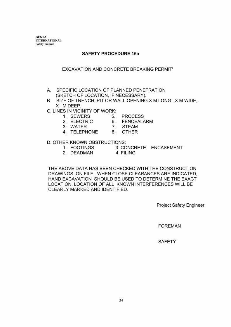
SAFETY PROCEDURE 16a EXCAVATION AND CONCRETE BREAKING PERMIT' A. SPECIFIC LOCATION OF PLANNED PENETRATION (SKETCH OF LOCATION, IF NECESSARY). B. SIZE OF TRENCH, PIT OR WALL OPENING X M LONG , X M WIDE, X M DEEP. C. LINES IN VICINITY OF WORK: 1. SEWERS 5. PROCESS 2. ELECTRIC 6. FENCEALARM 3. WATER 7. STEAM 4. TELEPHONE 8. OTHER D. OTHER KNOWN OBSTRUCTIONS: 1. FOOTINGS 3. CONCRETE ENCASEMENT 2. DEADMAN 4. FILING THE ABOVE DATA HAS BEEN CHECKED WITH THE CONSTRUCTION DRAWINGS ON FILE. WHEN CLOSE CLEARANCES ARE INDICATED, HAND EXCAVATION SHOULD BE USED TO DETERMINE THE EXACT LOCATION. LOCATION OF ALL KNOWN INTERFERENCES WILL BE CLEARLY MARKED AND IDENTIFIED. Project Safety Engineer FOREMAN SAFETY
35
GENTA INTERNATIONAL Safety manual SAFETY PROCEDURE #17 LADDERS A. PURPOSE: To provide guidelines for the proper use and inspection of ladders throughout this project. B. RESPONSIBILITIES: Contractors C. INSPECTION OF LADDERS: Ladders with broken or missing rungs or steps, broken or split side rails, or other faulty or defective construction will be returned to the tool room, and tagged 'DO NOT USE!'. The tool room attendant shall have the ladder repaired or destroyed. The color coding scheme as found in the Assured Grounding Program will be used as the basis for quarterly inspections. D. USE OF LADDER: Job built wooden ladders must be approved by the Safety Manager and will be used only as a means of egress from excavations or vaults. E. LADDERS: A ladder is the primary method of gaining access and egress to a work area. 1. Ladders must be secured, in place, by one or more of these methods. Someone holds the ladder until the person reaches where they can secure the ladder by blocking or chocking the ladder where k cannot be displaced. The least acceptable method to secure a ladder is to have someone stand there the whole time and hold ft. 2. Use ladders that fit the job to be performed; answer these questions. a. Is ft long enough? Maintain at least one (1) meter or more above the object it is resting on or being secured to.
b. Is it the right type of ladder? Do not use a step ladder as a straight ladder or vice versa. Do not use the center section of an extension ladder as a step ladder or straight ladder.
C. Do not use a conductive metal ladder in the energized area/units.
36
GENTA INTERNATIONAL Safety manual
PROCEDURE #17 - Ladders 3. Always face the ladder when you are on it. Do not stand partly on the
ladder and on another object. 4. As soon as you step on the ladder or reach where you are going, tie off yodr safety belt Immediately. 5. D6 not carry objects in your hands while you are climbing a ladder. Use a bucket and rope or other arrangement to get the materials and tools where you have to work. 6. Maintain three points of contact at all times on the ladder - two feet and one hand or two hands and one foot, as you climb on the ladder.
7. Do not block a door or walkway without making sure ladder will not be displaced
8. Do not work on the top rungs of a step ladder. The step ladder must be level to be safe. 9. Loose objects will not be used to maintain a level object, you must clean up ft necessary to maintain your ladder in a level position. 10. Moving a ladder with a person on ft is specifically forbidden. 11. Defective ladders will be destroyed immediately, a ladder without safety feet will be repaired immediately. 12. Sliding down the runner or jumping from the ladder is forbidden. 13. Maintain a pitch of one out to four in height on portable ladders.
14. Ladders shall be maintained when not in use in a dry location and protected from damage. Ladders will be secured from accidental displacement while not in use.
37
GENTA INTERNATIONAL Safety manual
SAFETY PROCEDURE #18 BARRICADE TAPE PROGRAM Three, (3) types of barricade tape will be utilized on thjs project and used as a visual warning for employees. Barricade tape does not offer physical protection for floor edges, roof edges, floor openings, etc., and shall not be used for physical protection. Listed below are three (3) different types of barricade tape and their intended proper usage. A. YELLOW/BLACK BARRICADE TAPE: This type of barricade tape shall be utilized to serve as a caution in order to indicate to employees that a potential hazard exists. Employee may enter without permission from craft supervisor. This type of barricade tape shall be used for, but not limited to the following: 1. Excavation one (1) meter or more in depth. 2. Identification of trip hazards, low hanging objects, etc. 3. Material storage on the site. B. RED BARRICADE TAPE: This type of barricade tape shall be utilized to indicate DANGER, and that possible serious injury may be present. NO EMPLOYEE, other than that craft assigned to work inside a RED barricade may enter without first obtaining permission from that craft supervisor. This type of barricade tape shall be used for, bin not limited to the following: 1. Overhead work. 2. Live electrical components 3. Scaffold under construction. 4. Around swing radius of equipment with a rotating super structure. 5. When testing high voltage cables (Hi-Potting) provide red barricade tape, high voltage signs and a watchman at both ends (at the substation and at the end of the cable). C. MAGENTA (PURPLE)/YELLOW: This type of barricade tape shall be used to indicate "DANGER-RADIATION," and that possible exposure may be present. This type of barricade tape is to be considered as an equal to red, in that, NO EMPLOYEES are allowed to be working or short cutting in this roped off area. This color is representative of X-Ray work being performed.
38
GENTA INTERNATIONAL Safety manual
PROCEDURE #18 - Barricade Tape Program D. BARRICADE ERECTION: Each foreman performing work that requires barricade tape to be erected shall: 1. Erect the tape to enclose the specific area to be protected only. Do not block passageways or accessways unless entirely necessary. If passageways or accessways must be blocked, contact your general foreman for coordination with other crafts and/or possible alternatives. 2. Erect tape in a secure and neat manner that will maintain a height of between one (1) meter and one and a half (1 1/2) meters from the floor or ground surface. A second strand shall be placed half the distance between the top strand and the ground. 3. The 'red tape' will be issued through the project safety office. The 'yellow/black tape' will be issued through the tool room. The only employees allowed to enter a RED barricade area will be that craft assigned to tasks by that craft foreman responsible for the barricade.
39
GENTA INTERNATIONAL Safety manual SAFETY PROCEDURE #19 COMPETENT PERSON DESIGNATION A. PURPOSE: To establish a uniform method of selecting, by definition, a competent person. B. RESPONSIBILITIES: GENTA Safety Supervisor and Chief Engineer . C. COMPETENT PERSON DESIGNATION: A competent person is one who, because of training and experience: - is capable of identifying existing or potential hazards in the job being performed. - is capable of identifying working conditions that are unsanitary, hazardous, or dangerous to the safety and health of the employee. - has the authorization to take prompt corrective measures to eliminate the above conditions. D. DESIGNATING THE COMPETENT PERSON: The Project Manager or Superintendent, in conjunction with the Safety Supervisor , designates the competent person, evaluates his or her performance and ensures that a competent person is available for a required activity. The Project Manager or Superintendent documents the designation of a competent person on the attached form. The original of the form is forwarded to the Safety Supervisor for recordkeeping. E. QUALIFICATIONS: The designated competent person must have an immediate knowledge of the subject, either by years of experience in the designated field, formal education, or specialized training in the: - Job or activity being performed - Current operations - Technology and controls - Potential hazards - Safety and health standards as applied
40
GENTA INTERNATIONAL Safety manual
SAFETY PROCEDURE 19 - Competent Person Designation
F. RESPONSIBILITIES: The competent person is responsible for complying with required operations, inspection, testing, repairs, machinery and equipment maintenance, and maintenance of an accident prevention program which includes such areas as: - Hoisting and lifting equipment - Electrical assured grounding - Excavation - Scaffolds - Radiation X-Ray procedure - Fire protection equipment - Motor vehicles
41
GENTA INTERNATIONAL Safety manual
SAFETY PROCEDURE #20
CONFINED SPACE ENTRY A. PURPOSE: To provide guidelines for the entry into confined spaces. B. RESPONSIBILITIES: Genta Safety Supervisor and Chief Engineer . C. CONFINED SPACE ENTRY Confined spaces are normally considered enclosures having limited means of access and egress, also to include adequate ventilation. These spaces include, but are not limited to: 1. Tanks, tank cars, vessels, bins, silos, boilers, enclosed skirts and other tank- like compartments usually with only a manhole for entry. 2. Open-topped spaces of more than 1.2 meters in depth, such as pits, vaults and vessels not subject to good natural ventilation. 3.Septic tanks, sewer, pipeline, underground utility tunnels and similar structures. Any supervisor performing work in a confined space shall complete, or have completed a confined space entry permit and insure all signatures and tests are performed PRIOR to allowing entrance by employees. This permit is good for one (1) shift only. This permit must be posted outside the confined space entrance as long as employees are inside. The number of employees allowed inside confined spaces must be kept to a minimum. (Confined space permit should be prepared by GENTA or Consultant attached.)
42
GENTA INTERNATIONAL Safety manual SAFETY PROCEDURE #21 FIRE PREVENTION GUIDELINES A. FIRE PREVENTION FOR CONSTRUCTION 1. Good Housekeeping shall be maintained iii all work areas. (Accumulation df flammables is prohibited.) 2. Fire protection equipment will be provided in all areas where combustible materials are present. Regular inspections will be made by the Safety Department to assure that fire extinguishers, hoses, reels and hydrants are in good working order. Use of fire hydrants, hose stations and PIV valves will be permitted only with authorization from the Safety Supervisor, or an actual emergency. 3. A clear access to all fire protection equipment will be maintained. (includes extinguishers, hose reels, hydrants, etc.) 4. Fire protection equipment is to be used only for that purpose. 5. Fire lanes inside of all buildings shall be maintained and kept clear for safe egress. 6. In certain plant areas, smoking will be permitted only in designated areas. 7. 'Strike anywhere' matches are not to be used on the project. B. FLAMMABLE LIQUIDS AND GASES 1. Only approved safety containers shall be used for handling, dispensing and storage of flammable/combustible liquids. 2. Storage of flammable/combustible liquids shall be only in an approved area and in an approved cabi,net or cage. C. CUTTING AND WELDING 1. The areas of welding and cutting operations (especially below) shall be continually watched during and immediately after the operation. 2. All welding and cutting operations shall have fire extinguishers within ten (1 0) meters and be accessible. Fire extinguishers for this use (stand-by fire watch) are to be supplied by the company doing the welding, not permanently installed fire extinguishers.
43
GENTA INTERNATIONAL Safety manual SAFETY PROCEDURE #21 - Fire Prevention Guidelines 3. Fire blankets are to be used to retain all sparks, slag or hot pieces of metal to prevent contact with a flammablelcombustible substance, electrical circuitry, machinery/equipment or people. 4. Practical welding screens are- to be used to protect personnel from ultra-violet rays. (flash burns) 5. For the elimination of possible fire in enclosed spaces as a result of gas escaping through leaking or improperly closed torch valves, the gas supply to the torch shall be shut off. Whenever the torch is not to be used or whenever the torch is left unattended for a substantial time, the torch and hose shall be removed from the confined space. Open and fuel gas and oxygen hoses shall be immediately removed from enclosed spaces when they are disconnected from the torch. 6. Open fire in the site is strictly forbidden.
44
GENTA INTERNATIONAL Safety manual SAFETY PROCEDURE #22
LIVE ELECTRICAL WORK A. Before any work is to be performed on live electrical cable, lines,and equipment or if the work you are performing will come in contact with live electrical cables, lines, or equipment, the …………………… Safety Supervisor must be advised. B. The Foreman or Supervisor must advise the Project Manager why the work must be done live and of the protective measures taken to protect employees from contact with any live electrical circuit. C. No one will work in or stand on a cable tray or raceway. The cable tray or raceways will not be used as a staging area for materials unless the cable tray has been completely covered with 20 mm plywood or equivalent that is rigidly secured to the cable tray or raceway. D. Cables outside the cable tray or raceways should be shielded from the work being performed with rubber blankets to protect the cable from damage. E. Only trained electricians will handle live electrical equipment with the exception of drop cords and construction tools used by craftsmen. Only trained electricians will service or maintain temporary electrical services in construction areas. F. Only the GENTA Safety Supervisor may approve work to be performed on any electrical system while the system is energized.Every effort should be made to de- energise the whole system. G. If de-energizing is not possible, all personnel involved will wear standard electrical lineman gloves, which meet all standards for voltage amounts within the system and the gloves have been inspected prior to use. H. If work on any live systems would cause the electrician to come into contact with a cable tray, plant piping or the plant grounding system, at least two rubber blankets shall physically separate the electrician from the plant grounding potential~ I. No one will work on a live electrical circuit, at any voltage, to pull wire, make termination or inspect wiring equipment or otherwise. There must be at least two trained electricians working together. J. Every precaution shall be made to assure the protection of employees with use of gloves, blankets, hot sticks, test equipment, physical barriers or any other steps necessary to prevent the employee from becoming energized in the electrical system.
45
GENTA INTERNATIONAL Safety manual SAFETY PROCEDURE #23 MOBILE EQUIPMENT: OPERATING & INSPECTION A. This procedure provides guidance for recording the condition of GENTA or Sub-contractor's equipment when arrives at the project site. B. No equipment will be put into service until it has been inspected and accepted by the Client Safety Supervisor . GENTA Chief Engineer will notify the Client Safety Supervisor one day before the arrival of any equipment at the job site. C. Equipment will be mobilized in good condition, requiring no service or repair and shall have all required safety devices intact and operable. Equipment mobilized that does not meet this criteria will be rejected and Contractor will remove it from site immediately. An inspection report will be used to verify the condition of incoming construction equipment and to verify that it is free of mechanical defects and/or safety deficiencies. D. The forms used are as follows: 1. Form A393-1 - For inspection of both hydraulic and cable-operated cranes 2. Form A393-2 - For inspection of tractors, excavators and forklifts 3. Form A393-3 - For inspection of trucks 4. Form A393 - For inspection of any type equipment not mentioned previously such as air compressors, manlifts, welding machines, etc. E. Concurrent with the inspection of incoming equipment, a safety inspection and an inspection of required safety devices will be conducted on each piece of equipment, The results will be recorded on the Safety Device Requirements for Construction Equipment Chart (Exhibit A) and the Definition of Safety Requirements for Construction Equipment (Exhibit B). Any deficiencies observed in the piece of equipment being inspected must be noted on the Form 70-9; the deficiency must be fully explained within the remarks section of the form; and the repairs made or corrective action taken must be noted on the Form 70-9. F. After the inspection of incoming equipment, a monthly safety inspection will be conducted with the results noted on Form 70-9. Any deficiencies observed will be noted and explained within the remarks section, and repairs made or corrective action taken will be noted on Form 70-9. G. On an annual basis, cranes shall be taken out of service, inspected by the Client Safety Supervisor and the results of that inspection recorded on the Annual Crane Inspection Form 70-9-1. Copies of this annual inspection should be permanently maintained in the equipment maintenance file and in the cab of the crane. Any deficiencies observed will be noted on Form 70-9-1 and explained within the comments section and repairs made or corrective action taken before placing the crane back into service.
46
GENTA INTERNATIONAL Safety manual SAFETY PROCEDURE #24
HEARING CONSERVATION A. Employe's hearing will be protected in accordance with this procedure and accepted hearing conservation measures. B. Supervision shall determine which job assignments could expose an employee to noise levels greater than 80 dBA, 8-hour Time Weighted Average (TWA). A continuing, effective hearing conservation program will be provided for each employee exposed to noise levels of more than 80 dBA, 8-hour TWA. The hearing conservation program will include: 1. Monitoring noise levels to identify work areas or specific equipment which exceed 80 dBA. Measurements will be performed using an ANSI Type 11 sound level meter set on the A scale, slow response. 2. Implementing feasible engineering and administrative controls to reduce employee exposures to 80 dBA, or less. 3. Training on the effects of noise exposure and the proper use of earplugs and earmuffs. 4. Providing and enforcing the use of adequate earplugs or earmuffs for employees who work in areas exceeding 85 dBA.
47
GENTA INTERNATIONAL Safety manual
SAFETY PROCEDURE #25
CRANE LIFT PROCEDURE (Critical Lifts) A. This procedure provides guidance for control of lifts with cranes which are considered to be critical lifts.and: not repetitive. Lifts that fall into this category are those lifts which: 1. A lift which exceeds 75% of the crane's rated capacity of the crane configuration. 2. A lift that requires two cranes to make the lift. 3. A lift that is to be made where the load or crane boom could fall on pipelines, vessels, or reactors containing flammable gases or liquids. 4. A lift where poles and derricks have been erected for a specific lift. B. INTERPRETATION Crane configuration as used in this procedure refers to such variables of the crane as boom length, boom angle, counterweight, outriggers, extended and set/tracks extended or retracted and attachments jib, headache ball, load block, lifting devices, etc.). All above items affect the gross capacity of the crane and shall be taken into consideration prior to lift. C. GUIDELINES If, in completing the permit, ft is determined the tift exceeds 95% of the crane configuration capacity for the greatest radius the load will achieve during pick, swing or set, the lift will not be made. By changing the crane configuration within manufacturing specifications a greater gross capacity may be gained, the change shall be made. If not, a larger capacity crane shall be obtained and used. D. RESPONSIBILITIES The Crane Lift Permit , omit , will be completed prior to the 'critical lift' by the supervisor of the lift. After the permit has been completed by the supervisor, the designated project personnel will review and sign off on the lift permit in the order listed on the permit. A copy of the permit will be placed in the cab of the lift-crane with the original filed in the project safety office. E. OTHER HAZARDS For any electrical or other hazard(s) involved or associated with the operations, the appropriate hazard permit will also be completed prior to the lift.
48
GENTA INTERNATIONAL Safety manual SAFETY PROCEDURE #26 FALL PROTECTION A. The standard operating method of completing a task that cannot be completed while standing on a floor or the ground is patent or a heavy duty scaffold with standard guardrails. B. If the standard operating method will not allow the accomplishment of the work, then the Project Manager, Chief Site Engineer , or Safety Supervisor must be notified that an alternative method would be used. C. Alternative methods that may be used include the following: 1. Any scaffolding without standard handrai Is, stationary or otherwise. 2. Ladders 3. Sitting, standing, climbing, or walking on a machine, equipment, pipe, or object to perform the work or to gain access or egress to or from the work. 4. Manbasket from a crane. 5. Suspended platform (staging, spider basket) D. Safety belts or harnesses are required at any time an employee is more than two (2) meters off the floor or ground is not protected by standard guardrails. Anchorage of the lanyard shall be to an object capable of supporting 2,500 kilograms. E. Ladders must be used to gain access or egress from an elevated work area. The ladder must be secured to prevent slippage and, if at all possible, attached directly to the scaffold or the elevated work area. F. When safety belts are the only form of fall protection to be used, employees will remain tied-off at all times while the employee is not protected by a standard handrail or on a ladder. G. Fall potential of two (2) meters or more on any side of the work area constitutes the need for fall protection. H. The fall distance at any one time shall be no greater than two (2) meters and every effort shall be made to reduce that distance lower than two (2) meters. Any time any employee is working over exposed rebar or operating equipment they shall be tied off. The lanyard shall be short enough to not allow the employee to strike this equipmentlrebar if they do fall.
49
GENTA INTERNATIONAL Safety manual SAFETY PROCEDURE #27 CRANE WORK NEAR OVERHEAD ELECTRIC AND HAZARDOUS PIPELINES A. The following procedure applies it a crane must operate where it is possible for ANY PART to come within five (5) meters of an energized electrical line or in transit if the crane can come within one (1) meter of lines up to 50 KV and three (3) meters from 50 KV to 345 KV.
1. The Client Safety Supervisor , Genta Site Chief Engineer , GENTA Safety Supervisor , the foreman in charge of the work and equipment are to be contacted .
2. These individuals will decide whether: (a) the line will be shut down; (b) the crane will be grounded; (c) an Electrical Department standby man is necessary; and (d) if protective equipment must be worn.
3. Written approval to proceed with the work will be given by the committee outlined above, after all precautions specified on the permit have been enacted. B. No crane shall be operated under these conditions unless:
1. A signal man is present whose sole function shall be to assure that clearances are maintained.
2. Signs and barricades are posted around the crane warning personnel to stay clear.
3. The crane operator is the only person on the rig. C. Cranes or other equipment having booms shall not be parked overnight or over a weekend directly under any high tension line, Booms must be lowered or tied off using load line. D. Precautions noted in this procedure apply to all electric lines. Similar considerations must be given to piping systems which contain potentially hazardous materials. E. Correct identification of all overhead electric lines is vital, since there is considerable resemblance between some high voltage lines and telephone' fines. F. A copy of this procedure will be posted in each crane cab. All Crane Operators will be Instructed to stay on the rig in case of contact with any electrical line. Men handling tag lines or attaching or disconnecting loads must wear tested Linemen's gloves of adequate voltage with protectors and rubber footwear.
50
GENTA INTERNATIONAL Safety manual
SAFETY PROCEDURE #28
CONCRETE AND REBAR A. General Requirements 1. No construction loads will be placed on a concrete structure or portion of a concrete structure unless, based on information received from a qualified person that the structure or portion of the structure is capable of supporting the loads. 2. All protruding reinforcing steel onto and into which employees could fall, shall be guarded to eliminate the hazard of impalement. 3. No employee shall be permitted to ride concrete buckets, nor work under concrete buckets while buckets are being elevated or lowered into position. Employees will be required to wear proper clothing, boots, gloves, hard hat and safety glasses to prevent cement burns. Employees applying cement, sand and water mixtures through a pneumatic hose will wear face protection in addition to safety goggles. 4. No employee shall be permitted to place or tie reinforcing steel more than 2 meters above any adjacent working surface unless the employee is protected by the use of a safety belt or equivalent tall protection. B. Equipment and Tools 1. Storage bins, sues and containers must be equipped with conical or tapered bottoms, and have mechanical or pneumatic control to pour the material. Entry into the storage facilities shall only be permitted in accordance with the lock and tag procedure in effect at that time. 2. Power and rotating type concrete troweling machines that are manually guided shall be equipped with a control switch that will automatically shut off the power whenever that hands of the operator are removed from the equipment handles. 3. Positive safety latches or similar safety devices shall be installed on all hydraulic or pneumatic gates of concrete buckets to prevent premature or accidental dumping. Buckets will be suspended from shackles or approved safety-type hooks. 4. All pipe supports of concrete pumping system will be designed for 100 percent overload. Compressed air hoses will utilize only fail-safe joint connectors to prevent separation of sections when pressurized. Tremies, elephant trunks, etc., sections will be secured with fail-safe chain or wire rope in addition to regular couplings or connections.
51
GENTA INTERNATIONAL Safety manual
SAFETY PROCEDURE #28 - Concrete and Rebar
5. Concrete buggies handles will not extend beyond the wheel on either side of thebuggy. Where there is a possibility of contact with energized electrical conductors, handles on bull floats will be constructed of non-conductive material or insulated with non-conductive sheath. 6. Blades of masonry saws must be covered with a semicircular enclosure to retain blade fragments. A method for retaining blade fragments shall be incorporated mt the design of the semicircular enclosure. 7. Mixers with 0.75 cubic meters or larger loading skips shall be equipped with a mechanical device to clear the skip of materials. And guardrail installed on each side of the skip. NOTE: All potentially hazardous energy sources must be locked out and tagged before performing maintenance or repair on equipment. C. Formwork / Shoring 1. Formwork and shoring will be designed, erected, supported, braced and maintained so as to safely support any and all vertical and lateral loads that may be imposed upon during placement of concrete. Drawings of plans showing the jack layout, formwork, shoring, working decks and scaffolding will be available at the job site. 2. All shoring equipment will be inspected prior to erection to determine that it is specified in the shoring layout and it is not defective. Defective or damaged shoring equipment must not be used for shoring under any circumstances. Erected shoring equipment will be inspected during and immediately before and after the placement of concrete. Damaged or weakened shoring equipment will be immediately reinforced or restored. 3. All sills for shoring will be sound, rigid and capable of safely carrying all vertical and lateral loads that may be impose upon them at anytime. All base-plates, shore heads, extension devices and adjustment screws will be in firm contact with the footing sill and the form material. Eccentric loads on shore heads and similar members must be designed for such loading. 4, Shoring for tiered single post shores and erected shoring must be designed and inspected by a qualified designer and by an engineer qualified in structural design.
52
GENTA INTERNATIONAL Safety manual
SAFETY PROCEDURE #28 - Concrete and Rebar 5. Single post shores must be vertically aligned, spliced to prevent misalignment, and adequately braced in two mutually perpendicular directions at the splice level. Each tier also must be diagonally braced in the same two directions. Single post shores should not be adjusted after the placement of concrete. 6. The spacing between towers and cross-brace spacing in erected shoring will not exceed that shown on the layout, and all locking devices will be in the closed position. 7. All shoring will be laterally supported by attachment to the structure. Free- standing masonry walls will be braced and supported to provide lateral stability against wind or other forces. 8. Re-shoring must be erected, as original forms and shores are removed, whenever the concrete is required to support loads in excess of its capacity. 9. Forms and shores (except those used for slabs on grade and slip forms) must not be removed until the concrete gains sufficient strength to support its weight and superimposed loads. Compliance with the plans and specifications for removal of forms and shores, and proper testing with an appropriate standard test method can help determine if the concrete has gained sufficient strength. 1O. Re-shoring also must not be removed until the concrete being supported has gained adequate strength to support its weigh and all loads upon it. 11. Employees removing formwork or shoring at elevations in excess of 2 meters will wear and use safety belts or harnesses when exposed to a direct fall where rescue would be done by a crane or cherry picker with lanyards being attached to a lifeline or the structure. 12. Steel rods or pipes or vertical slip forms on which jacks climb, or by which forms are slip forms must be provided with scaffolds or work platforms where employees are required to work or pass. 13. Jacks and vertical supports must be positioned so that the loads do not exceed the rated capacity. Jacks or other lifting devices must be provided with mechanical dogs or other automatic holding devices to support the slip forms in case of power supply or lifting mechanism failure. 14. The form structure must be maintained within all design tolerances during the jacking operation and must not exceed the safe rate of lift.
53
GENTA INTERNATIONAL Safety manual
SAFETY PROCEDURE #28 - Concrete and Rebar
15. A limited access area must be established and barricaded before precast concrete work begins. Only employees actively engaged in erecting the precast well be permitted to enter this area. Employes shall not be permitted under precast concrete members when they are being tilted or lifted. 16. Precast wall unite, structural framing, and tilt-up wall panel must be adequately supported to prevent overturning and to prevent collapse until perm 17. Lifting hardware also must be capable of supporting at least five (5) times the maximum intended load. D. Masonry Construction 1. A limited access zone must be established and barricaded whenever a masonry wall is being constructed. The limited access zone must be established prior to the start of construction of the wall; must be equal to the height of the wall to be constructed, plus 1.25 meters, must run the entire length of the wall and must be established on the side of the wall which will be unscatfolded. 2. Only employees actively engaged in constructing of the wall will be permitted to enter the barricades limited access zone. 3. This barricade will remain in place until the wall is adequately supported. 4. Masonry wall over 2.5 meters must be adequately braced to prevent overturning and to prevent collapse, The bracing must remain in place until permanent supports are in place. E. Operations involving Rebar 1. Employees will not be permitted to work above vertically protruding reinforcing steel unless ft has been protected to eliminate the hazard of impalement. Elimination of this hazard may be accomplished by bending the steel over or covering the protruding ends of the steel with timber, rebar caps, or other, suitable material. 2. Employees working more that 2 meters above any adjacent working surface placing and typing rebar will wear safety belts and sue such safety belts with the lanyards attached to a lifeline, the structure, or other substantial object. Employees will wear gloves when placing and tying rebar.
54
GENTA INTERNATIONAL Safety manual
SAFETY PROCEDURE #28 - Concrete and Rebar
3. Reinforcing mats (used as a walkway) will be provided with planking to ensure safe footing, A two-part sling will be used when moving bundles of rebar over 6 meter in length by crane. Wire mesh rolls will be secured at each end to prevent recoiling action. Reinforcing steel (rebar) for walls, piers, columns, and similar vertical structure will be guided and supported to prevent collapse.
55
GENTA INTERNATIONAL Safety manual SAFETY PROCEDURE #29 HOUSEKEEPING AND SITE TIDINESS A. Materials and equipment delivered to site prior tb installation will be stored in warehouses, stores, laydown areas or elsewhere only with the approval of Client Site Manager. Any materials or equipment off loaded and left in a location not approved by Manager will be moved to an approved location . B. All work areas will be kept as tidy as practical. The accumulation of packaging, offcuts, debris and other unwanted material will not be allowed. Tradesmen will tidy up after themselves and each work area will be cleaned and the debris removed at least once per day. C. Waste material will be disposed of properly D. GENTA Chief Engineer will submit proposals for the cleaning of his work area to Manager who, when they are agreed, will closely monitor compliance therewith. E. Cables, hoses and pipework supplying power to work areas will be neatly laid or hung so as not to interfere with access or be a trip hazard. F. In any areas of restricted access, the highest standard of housekeeping will be required from all persons working there .
56
GENTA INTERNATIONAL Safety manual SAFETY PROCEDURE # 30 ROADS A. Clear road access will be maintained on the site. Any work, such as excavation, vehicle loading / offloading or the sitting of cranes or other large plant which reduces the width of the carriageway or otherwise interferes with access, may be undertaken only with the prior agreement in writingClient representative and Genta site manager Proposals for such operations will be submitted to Manager before work commences. These proposals will ensure that sufficient access for the emergency services is maintained at all times and provide for effective traffic management.