Universidad de los Andes Faculty of Engineering Department of Electrical Engineering and Electronics Procedure of Fault Management in Distribution Networks with DG Thesis presented by Andres Felipe Botero Valencia To obtain the degree of Electrical Engineer Supervised by Mario Alberto R´ ıos Mes´ ıas, Ph.D Sustained on may 30, 2012
Transcript
Universidad de los Andes
Faculty of Engineering
Department of Electrical Engineering and Electronics
Procedure of Fault Management in Distribution Networks with DG
Thesis presented by Andres Felipe Botero Valencia
To obtain the degree of Electrical Engineer
Supervised by Mario Alberto Rıos Mesıas, Ph.D
Sustained on may 30, 2012
Acknowledgements
I would like to extend my sincere thanks to my advisor Professor Mario Alberto Rios for his
guidance throughout this project.
I would like to thank my family, for always being there for me when I needed them, and
always encouraging and supporting me in my studies.
I want to thank my girlfriend for her support and patience by giving me time to finish this
Continuity and quality are two indispensable terms to ensure the satisfactory operation of
an Electric Power System (EPS). Continuity of the service acquires special importance when
you have in mind that electricity cannot be significantly stored and that any interruption will
have a direct and immediate impact on almost all processes in the industry. In the same
way, quality becomes an indispensable requirement to guarantee the correct operation of the
equipment connected to the network.
When a fault occurs in the EPS, magnitudes associated to this reach values outside of their
normal operation ranges and some areas of the system can start to work unbalanced, losing
continuity and quality of the service. Therefore, the design of an electric system must con-
template the occurrence of aleatory and unexpected faults, and design a protection system
that would minimize the effects of these faults in the system.
The classical challenges of electrical protections are being lately altered by a trend to power
systems more energy-efficient, reliable, and environmentally friendly. This trend is giving a
start to concepts as DG and is bringing new technical challenges for engineers in several fields.
One of these fields in which the impact of this trend is important, is in electrical protections
[8], as the functionality and reliability of the system depends on it. The main effect is given
by the constant change in the topology of distribution systems, which alters the conditions
that were initially used for the adjustment of the protection devices. For this reason, modern
protection systems should be able to adapt themselves to the continuous changes, keeping the
basic criteria of sensitivity, selectivity, and speed, demanded by a coordinated and reliable
system. Besides, since electrical distribution systems are increasingly bigger and intercon-
nected, it is important not only to focus on the immediate reaction upon faults, but also to
have in mind that must exist a complete fault procedure, from the detection of fault to the
efficient and fast restoration of the energy supply in the entire power system.
4
Chapter 1. Introduction 5
Connecting generators to a distribution network would change its properties significantly.
Mainly, the short-circuit currents will vary and its flow paths will be more complicated. On
the other hand, a fault clearing will cause a big change in system’s topology and will allow
some part of the network, if is possible, to operate in island mode. Therefore, some problems
that appear are loss of selectivity, earth-leakage protection, disconnection of generators, and
islanding among others [9]. As a consequence, classical protection techniques may become
inadequate and protection parameters will have to be updated frequently.
Several researches have been performed on how to tackle the resultant problems of applying
DG into distribution networks and on how to maximize the benefit of such changes for in-
creasing reliability on the system. For example, in [12][5][23] adaptive protection schemes have
been stated and some of them have been implemented on part of a real distribution network,
showing the advantages of using such schemes. Other, like [18][15], have tried to show the
microgrids operation, protection and control issues, and its possible solutions. In [23][13][11],
the proposed schemes are based on a zoning procedure and its main objective is to adjust
and maintain coordination of some protective devices placed between the determined zones.
Almost all of them are thought with micro-processed relays with a communication module.
Additionally, this subject has caught the attention of different control areas, e.g., [7][25][26]
have proposed schemes that are based on a multi-agent architecture, where each digital relay
in the system is an agent with the ability to process information, take decisions, and interact
with other agents. Although the proposed solutions have been different, all of them agree
that shutting down all DG when a fault occurs can be impractical and that is necessary to
implement an adaptive philosophy in the protection schemes.
Given the importance of protection systems to ensure the continuity and quality of the elec-
tricity supply service, the objective of this project is to state a procedure of fault management
in radial systems when DG is incorporated. In order to meet this objective, it is necessary to
establish the required steps to detect faults, isolate faulty zones, detect and create possible
island modes, and finally restore the total operation of the system. Besides, the proposed
procedure should identify the required adjustments for the protection devices involved in the
system. Furthermore, a computational tool is developed to show the proposed procedure in
an interactive simulation environment, which gives information about the system and its pro-
tection devices as well as messages in each step of the protection procedure after a change in
the system is detected. As mentioned earlier, throwing off all DG from the system every time
a fault occurs would make the system very unreliable. Thus, the whole protection procedure
is based on an independent adaptive scheme that would not undermine the system reliability
after connecting DG.
Chapter 2
Electrical Protections
Modern design of power systems provides different strategies to decrease probability of faults,
however is economically and physically improbable to remove them totally. Thus, an appropri-
ate reaction to the occurrence of faults becomes completely necessary in order to mitigate its
effects on the system. Fault management is undoubtedly one of the most important functions
to decrease the outage times in the electricity supply. This management includes everything
from fault detection to both partial and total restoration of the energy supply in the system.
A fault or perturbation is defined as any unplanned change in the operation variables of a
power system. These faults can be caused by different internal or external reasons and present
undesired consequences on the operation of the system and its integrity.
Causes:
• Atmospheric discharges. (External)
• Breaking of conductors, insulators and structures due to earthquakes, winds, snow,
vandalism, among others. (External)
• Insulator damage caused by animals or environmental factors. (External)
• System operation switching. (Internal)
• Energization of equipment. (Internal)
Consequences:
• Equipment overheating, lines incineration, increase of line sag.
• Severe voltage fluctuations.
6
Chapter 2. Electrical Protections 7
• Unbalance that cause inappropriate operation of equipment.
• Instability of power system.
• Outages in the electricity supply.
• Severe damage to equipment or people.
There is a general classification for faults in electric power systems, which identify them ac-
cording to its duration:
Transient or Temporary Faults: This kind of faults are due to momentary situations
that cause anomalies in the system and can be cleared before serious damages occurs either
because they are self-cleared or because the fast action of a protection system. The clearest
examples of these faults are atmospheric discharges or momentary contacts of lines with the
branches of trees.
Permanent Faults: This kind of failure persists despite the intervention of protective equip-
ment and cannot be cleared until the direct intervention of maintenance personal. Some of
the clearest examples of these faults are the break of lines, falling of support structures and
the equipment breakdown in the system.
2.1 Fault Analysis
There are several tasks in the power system, electrical protections mainly, that require a pre-
cise knowledge of the values associated with faults occurring in the system. Such values are
obtained through fault analysis, in which the fault current levels, short circuit capacity and
pos-fault voltages are calculated.
The formulation of the analysis of faults in sinusoidal steady state, is understood if is analyzed
the behavior of the main source of the short circuit current in the power system, the syn-
chronous generator. The figure 2.1 shows the short circuit current of a synchronous generator.
From figure 2.1 is clear that current in the generator begins with a high value and tends
to decrease over time, so that three periods can be distinguished. The first one associated
with the biggest current value, known as transient current (I”), the second one known as
subtransient current (I’), and the last one known as steady-state current (I). The direct-axis
reactance of the generator corresponding to each period or current value is denoted as Xd”,
Chapter 2. Electrical Protections 8
Figure 2.1: Short circuit current in a synchronous generator [21].
Xd’, and Xd respectively. The behavior of these two variables in a synchronous generator
after a fault occurs are shown in 2.2.
The phenomenon associated with the occurrence of a fault, has certainly a dynamic character.
However, due to the variables of interest and knowing the required amount of fault analysis,
this phenomenon is analyzed in steady-state. For the purpose of this dissertation, short circuit
analysis for three-phase fault and mono-phase fault are going to be considered.
Figure 2.2: Behavior of current (Left) and reactance (Right) after a fault occurs [21].
2.1.1 Three-Phase Faults
This faults are considered as symmetrical faults, keeping the balance of the system (three
equal currents out of phase in 120 degrees). The fault can occur between the three lines or
between the three lines and ground. By keeping the system balanced the calculations are
easier as shown below [1].
I3φfault =Vf
ZTH + Zfault(2.1)
where I3φfault is the fault current, Vf is the voltage just before the fault occurred, ZTH is the
Thevenin impedance in the fault site, and Zfault is the fault impedance. Is important to note
Chapter 2. Electrical Protections 9
that normally the system is in a common base (p.u) and if so, the voltage just before the fault
occurred is taken as 1 p.u.
A common way for this calculation in computational means is the use of the impedance matrix
(ZBus, which has inherently the Thevenin impedance of each bus in its diagonal. So, assuming
that the impedance matrix is in p.u, the equation would be given by 2.2.
Ii3φfault =1
Zii + Zfaultp.u(2.2)
where Ii3φfault is the fault current in the bus i, Zii is the value of the element ii in the
impedance matrix, and Zfaultp.u is the fault impedance in p.u.
2.1.2 Single-Phase Faults
These are called asymmetrical faults because the balance of the system is lost. In this case
is required an analysis method that provides a convenient way to deal with the asymmetry
problem. This is why in 1918, Charles Legeyt Fortescue, demonstrated that any set of N
unbalanced phasors could be expressed as the sum of N symmetrical sets of balanced phasors,
for values of N that are prime. Only a single frequency component is represented by the
phasors. Essentially, this method converts three unbalanced phases into three independent
sources, which makes asymmetric fault analysis more tractable [21].
So, three unbalanced vectors of a three-phase system can be decomposed in three balanced
systems of vectors. These three balanced systems are designated as:
• Positive sequence components, which consist of three phasors of equal magnitude, sep-
arated 120o, rotating in the same direction as the phasors of power system under con-
sideration.
• Negative sequence components, which consist of three phasors of equal magnitude, sep-
arated 120o, rotating in the opposite direction as the positive sequence.
• Zero sequence components, which consist of three phasors equal in magnitude and in
phase with the others, rotating in the same direction as the positive sequence phasors.
Thus, the relation between voltages and currents of any three-phase system and its symmet-
rical components is defined by the matrix relation 2.3.
Chapter 2. Electrical Protections 10
Va
Vb
Vc
=
1 1 1
1 a2 a
1 a a2
Va0
Va1
Va2
(2.3)
where [Va, Vb, Vc] are the phase voltages, a is the operator defined by 1∠120o, and [Va0, Va1, Va2]
are the zero-sequence voltage, positive-sequence voltage, and negative-sequence voltage, re-
spectively. The matrix relation works in the same way for currents.
In the same way, in order to analyze an asymmetrical system all the impedances must be
expressed as positive-, negative- and zero-sequence components. The line impedance is equal
for positive and negative sequences but different for the zero sequence. For generators and
transformers, positive and negative sequences are modified just in the impedance value, but
the zero sequence impedance in these cases is a little more difficult to find. The figure 2.3 shows
zero sequence connections for generators and the figure 2.4 shows zero sequence connections
for transformers.
Figure 2.3: Equivalent zero sequence networks for generators [21].
Chapter 2. Electrical Protections 11
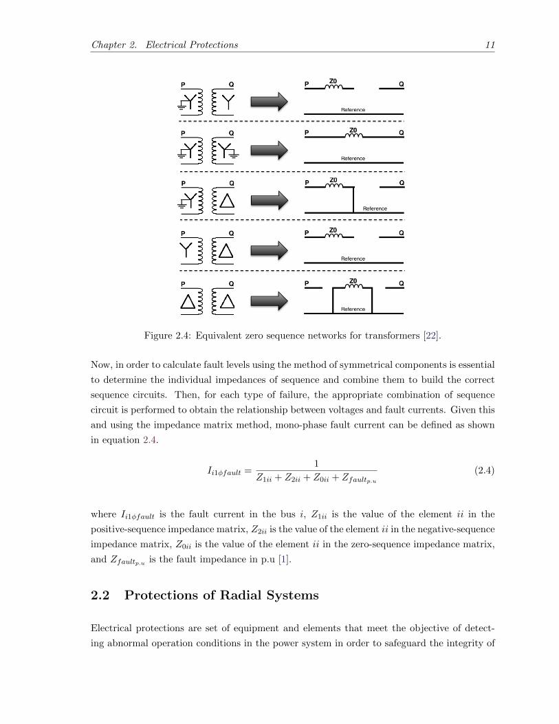
Figure 2.4: Equivalent zero sequence networks for transformers [22].
Now, in order to calculate fault levels using the method of symmetrical components is essential
to determine the individual impedances of sequence and combine them to build the correct
sequence circuits. Then, for each type of failure, the appropriate combination of sequence
circuit is performed to obtain the relationship between voltages and fault currents. Given this
and using the impedance matrix method, mono-phase fault current can be defined as shown
in equation 2.4.
Ii1φfault =1
Z1ii + Z2ii + Z0ii + Zfaultp.u(2.4)
where Ii1φfault is the fault current in the bus i, Z1ii is the value of the element ii in the
positive-sequence impedance matrix, Z2ii is the value of the element ii in the negative-sequence
impedance matrix, Z0ii is the value of the element ii in the zero-sequence impedance matrix,
and Zfaultp.u is the fault impedance in p.u [1].
2.2 Protections of Radial Systems
Electrical protections are set of equipment and elements that meet the objective of detect-
ing abnormal operation conditions in the power system in order to safeguard the integrity of
Chapter 2. Electrical Protections 12
equipment and people, and to maintain normal conditions so that an acceptable service can
be provided. It is important to clarify that a protection system will not prevent faults, but
in case of the occurrence of a fault it reacts to lessen or eliminate the effects on the system,
isolating the detected fault as soon as possible and trying to maintain continuity of the service
in most of the system. As a secondary function of protection systems would be the indication
of fault location and fault type [6].
The basic cycle comprising a protection system begins with the measurement of various pa-
rameters which are altered each time a fault occurs, such as voltage, current, frequency, angle’s
phase, power factor and polarity. These parameters are taken up by transformers due to the
magnitudes handled and then are sent to a relay which decides if exists an abnormal condition
and sends a signal to a switching device in order to take action and minimize the effects of
this failure on the system. The basic process of a protection system when a fault occurs is
shown in 2.5.
Figure 2.5: Basic process in a ESP when a fault occurs.
Among the functions to be performed by a protection system are: isolate permanent faults,
minimize the number of faults, minimize the effects of temporary faults, prevent equipments
damage, minimize troubleshooting time, minimize partial or total restoration time of the
system, among others. These functions must be met to ensure the following features in the
ESP [10]:
• Selectivity: Allows to discriminate the location of the equipment or element affected.
• Speed: Operation in the shortest possible time after a fault.
• Sensitivity: The protection system must operate for all faults no matter how small.
• Security: Protections should ensure operation in all cases required.
• Support: Secondary protection must operate if the primary did not.
• Coordination: Selecting and setting protective devices to clear a fault and/or isolate
the affected part.
Chapter 2. Electrical Protections 13
The general philosophy of a protection system is to divide the electrical system in defined
zones that are adequately protected and that can be disconnected when a fault occurs within
any of them, allowing the system to continue in service as far as possible [4].
That is why the protection of electrical systems is considered a demanding task that requires
different engineering principles either to develop fault current calculations and determine the
nominal features of equipments as to coordinate properly each of these in the system. There
are several devices to meet all the requirements presented above, however for the purpose of
this dissertation we will focus only in overcurrent protection devices for distribution networks.
2.2.1 Overcurrent Relays Coordination
Coordination of overcurrent relays is necessary to obtain selective tripping. The first rule of
protective relaying is that the relay should trip for a fault in its zone. The second rule is that
the relay should not trip for a fault outside its zone, except to back up a failed relay. This
coordination will ensure that the backup relay has sufficient time delay to allow the primary
relay to clear the fault [28]. In general overcurrent relays to a characteristic function, which
gives the operation time of the relay in terms of its load current, its pick-up current and a
time multiplier setting.
t =α ∗ TMS
((IFault/IPick−up)β − 1(2.5)
where TMS is the time multiplier setting of the relay, IFault is the maximum fault current
through the branch and IPick−up is the pick-up current of the relay, which is given by the load
current multiplied by a factor, typically 1.5 for distribution circuits. The constants α and β
determine the type of curve of the relay’s operation, its values are shown in table 2.1.
2.2.2 Reclosers
A recloser is a circuit breaker equipped with a mechanism that can automatically close the
breaker after it has been opened due to a fault. Unlike conventional circuit breakers and fuses,
which require a technician to visit the site of an open breaker or blown fuse to restore service
caused by to the fault, a recloser can automatically attempt to close the circuit. Since most
overhead power line faults are transient (i.e. caused by a lightning strike), the use of reclosers
is very important in distribution networks.
Since the beginning of reclosers, its philosophy has been framed by an automatic reaction;
however, due to the new challenges presented by power systems, reclosers are evolving to
Chapter 2. Electrical Protections 14
Table 2.1: Form constants for exponential equation by IECType of Curve α β
Standard Inverse 0.14 0.02
Very Inverse 13.5 1
Extremely Inverse 80 2
Large Inverse 120 1
more complex systems integrating microprocessors, communication modules, remote controls,
among several other new features. This has led to the development of systems known as smart
reclosers.
There are several companies developing new technologies for reclosers, among which are
Siemens with its Type SDR Distribution Recloser [19], ABB with its three-phase recloser
OVR [2] and Noja Power with the OSM recloser [16]. These and other companies are trying
to improve recloser features to be used in smart grids protection and control. A block diagram
that shows the some of the modules and features that can have ”smart reclosers” is in figure
2.6.
Figure 2.6: Smart recloser block diagram. [16]
2.3 Distributed Generation
Current literature does not use a consistent definition of DG, which varies specially in terms
of type of resource and capacity. For the purpose of this project we will take a general the
definition given in [3], where DG is defined as electric power generation within distribution
networks or on the customer side of the meter.
The continuous grow of electricity demand, and the need of modern society for a secure and
Chapter 2. Electrical Protections 15
high quality supply, has led DG to be one of the most relevant topics not just for the electric
field but also for all engineering areas, due to the numerous challenges that this entails.
The table 2.2 shows the general advantages and disadvantages (Challenges) that brings the
incorporation of DGs on the current power system [9].
Table 2.2: Advantages and Disadvantages of Distributed GenerationAdvantages Disadvantages (Challenges)
Reduction of losses in transmission anddistribution networks.
Increase in reliability and service qual-ity if regulations are met.
Greater control of reactive power andvoltage regulation.
Better adaptation to changes in de-mand.
Increased competition and marketpower would decrease.
Greater flexibility, reducing depen-dence on centralized system.
Efficient use of energy sources and in-corporation of cleaner resources.
Requirement of new schemes for theoperation and maintenance of such sys-tems.
Higher investment costs, especially forsome renewable technologies.
Greater decentralization can hinder thesystem’s security guarantee and evenincrease the operating costs.
Environmental hearing pollution nearconsumers, in some cases.
One of the main issues that should be analyzed in networks with DG, is the impact of it in
electrical protections. The setting of electrical protections is based on the current state of
the system, so it is evident that any change would alter system parameters and would make
inadequate the classical protection techniques. Moreover, current distribution systems are
planned as passive networks, carrying the power unidirectionally from a generator downstream
to the loads, so it is also clear that incorporating distributed generators would change the
initial philosophy of the system. The main issues regarding electrical protections when DG is
incorporated, are shown below.
• It would affect the short-circuit amplitude, direction and duration.
• It would reduce fault detection sensitivity and speed.
• It would reduce reach of impedance relays.
• It would affect the voltage profile and cause reverse power flow.
• It could cause improper islanding and auto-reclosure.
Chapter 2. Electrical Protections 16
One of the simplest protection issues when connecting a distributed generator is illustrated
in figure 2.7.
Figure 2.7: System without DG (Left) and with DG (Right).
2.4 State of the Art
In the last years, some adaptive protection schemes have been proposed to ensure the correct
adjustment of protection functions based on the requirements of the power system. Some of
these works are shown in 2.3. Several of this schemes are based on communications networks,
which would have to meet all the requirements of some standards as IEC-61850 or IEEE-1547.
Table 2.3: State of the art, adaptive protection schemesReferences Description
[12], [11],[23], [13]
The proposed schemes in this references are based on a zoning proce-dure. The main objective of these schemes is to adjust and maintaincoordination of some protective devices placed between the mentionedzones. Almost all of them are thought with micro-processed relays witha communication module.
[7], [26], [25] These proposed schemes are based on a multi-agent architecture, whereeach digital relay in the system is an agent with the ability to processinformation, take decisions, and interact with other agents. These aredecentralized schemes with a zoning procedure proposal in the system.
[20], [27], [24] These schemes are based mostly in communication networks. The pro-tection devices are programmed in a remote mode. The reconfigurationprocess is based on offline calculations and a very extensive events table.
Chapter 3
Adaptive Management of Electrical
Protections
Many researchers in their first approach to this topic said that if protection scheme is not
changed, the only way to maintain coordination of protection devices in presence of an ar-
bitrary amount of distributed generators is to disconnect all DG instantaneously in case of
fault. However, this solution is not practical as it wastes the advantages of DG on helping
with reliability on the system, so is important to think in protection systems with an adap-
tive philosophy. More specifically, we have to consider the incorporation of protections devices
that modify its adjust parameters automatically, based on the operating conditions.
Traditional protection schemes of radial systems are based mostly on fuses and relays located
in distribution substations, these devices react when a fault occurs and isolate the part of
the system where the anomaly is located. Later, when the faulted element is fixed, human
intervention is needed in order to restore the electricity supply to the corresponding circuit.
If a distributed generator is introduced, some adjustments should be made manually to the
protections devices and besides, as mentioned earlier, a fault in any bus of the system would
mean the disconnection of all distributed generators in the system until the fault is fixed. This
behavior is not suitable for the future conditions of power systems and even is not optimum
for the current necessities. Hence, the following items must be taken in mind in order to meet
the requirements of an adaptive philosophy in the electrical protection system.
• For the purpose of having an appropriate response to anomalies in the system, the
protection devices should be able of making an automatic reconfiguration, this means
without human intervention.
• Protection devices must have a communication module, which would help in the correct
operation and coordination of the devices to have the best possible operation.
17
Chapter 3. Adaptive Management of Electrical Protections 18
• If a fault occurs, distributed generators should be able to attend part of the demand in
order to increase the reliability of the entire system. This action of isolating part of the
system to operate in an independent way, should be made without human intervention.
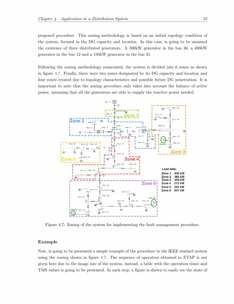
In view of these considerations, a procedure for managing faults in systems with DG is going
to be given. This procedure would be based on an initial operating condition of the system,
which would be given by certain zones in the system determined mainly by the capacity and
location of distributed generators.
3.1 Zoning Procedure
An ideal system would have a recloser device in each one of its branches, however this is
economically infeasible, thus a pertinent zoning of the system is needed. These zones would
be determined by the location and capacity of each distributed generator. The idea is to start
at nodes with DG and extends each zone downstream as long as the DG within it is capable
of supplying the peak load of that zone. When the peak load of the zone exceeds DG capacity,
the end of the zone is reached, and a recloser must be placed in the beginning and in the end
points of the zone, if such points are connected to other zones. If another DG is found while
the zone extends, the zone keeps growing until generation capacity of both is reached. It‘s
important to note that, when DG’s capacity is higher than the load located in its downstream
network, zone extension should be considered upward. The size of the zones that do not have
DG should not be too large, so if a new DG is placed it can attend the demand of the zone.
Clearly, the final decision of the amount of reclosers and thus the size of the zones will be
always influenced by economical factors.
With this procedure the system will be divided into two categories of zones. First, zones
without DG, so their load is fully supplied through the main source. Second, zones which
includes at least one DG and are able to operate in island mode. The final scheme of the
system, after the zoning procedure has been carried out, is shown in figure 3.1, where each
zone represents a group of nodes of the system.
3.2 Proposed Protection System
So far, its clear that the aim of this protection procedure is to appropriately coordinate and
control the recloser units that divide each zone, taking advantage of DG to improve the relia-
bility of the system. To meet this objective, is essential to determine the equipment features
that are needed and state an operation philosophy for the protection system.
Chapter 3. Adaptive Management of Electrical Protections 19
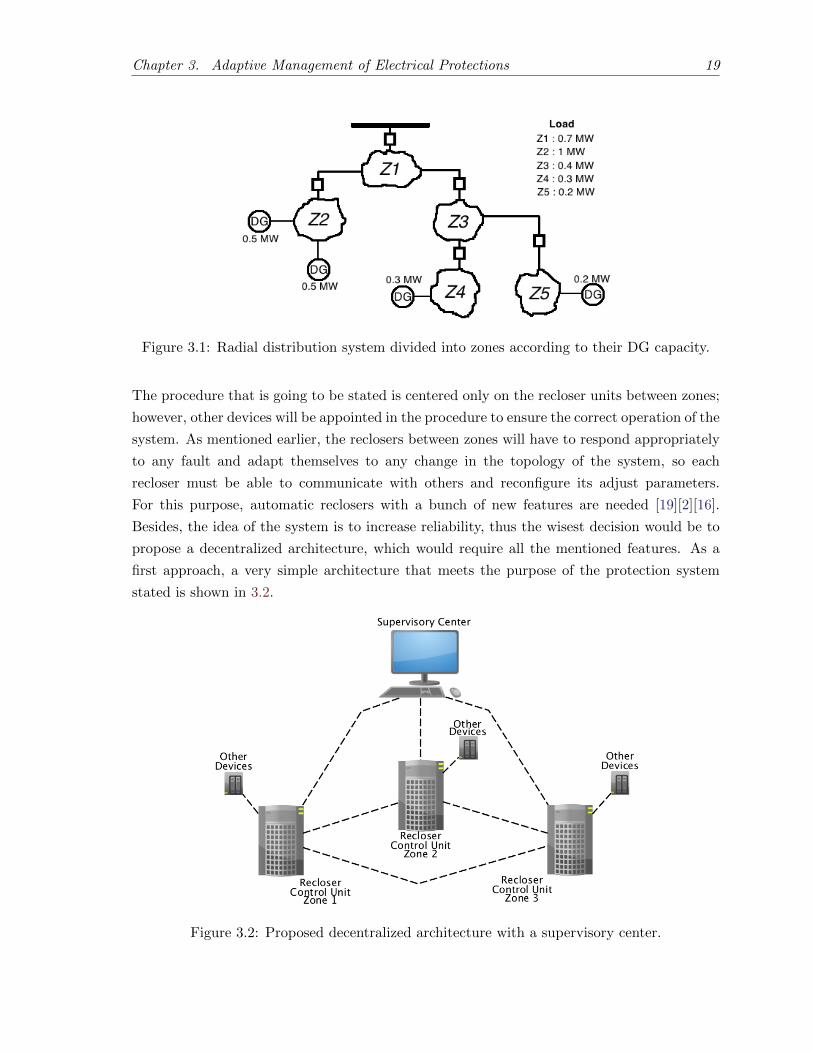
Figure 3.1: Radial distribution system divided into zones according to their DG capacity.
The procedure that is going to be stated is centered only on the recloser units between zones;
however, other devices will be appointed in the procedure to ensure the correct operation of the
system. As mentioned earlier, the reclosers between zones will have to respond appropriately
to any fault and adapt themselves to any change in the topology of the system, so each
recloser must be able to communicate with others and reconfigure its adjust parameters.
For this purpose, automatic reclosers with a bunch of new features are needed [19][2][16].
Besides, the idea of the system is to increase reliability, thus the wisest decision would be to
propose a decentralized architecture, which would require all the mentioned features. As a
first approach, a very simple architecture that meets the purpose of the protection system
stated is shown in 3.2.
Figure 3.2: Proposed decentralized architecture with a supervisory center.
Chapter 3. Adaptive Management of Electrical Protections 20
In this architecture, all the recloser units interact with each other and with other devices
in an independent way, so the supervisory center, as its name implies, will just ensure that
the system is operating correctly, gather some information of the system and send some
information signals to the reclosers. Below, are going to be described the interactions between
devices and is going to be stated the procedure of fault management.
3.3 Procedure of Fault Management
The expected behavior of the system can be briefly described in three stages, as shown in
figure 3.3. These three stages represent the adaptive philosophy that, as mentioned earlier, is
required to increase the reliability of radial systems with DG.
Figure 3.3: General procedure of the system when a fault occurs.
Initially, when the system is operating in normal conditions, the recloser units are monitoring
to detect a fault or a change in DG. If a change in DG is detected, the system has to process
the change and reconfigure appropriately the protection devices. On the other hand, if a fault
is detected, the corresponding recloseres have to automatically clear the fault and all the DG
located in that zone, is disconnected. After this, the possibility of each zone to operate in
island mode is assessed and the islands are created. The system would have to adjust again
appropriately the protection parameters. At this moment, the system will be divided into
three types of zones: zones without electricity supply, zones operating in islanding mode and
zones supplied by the main source. The system keeps working in this way until the faulted
element is fixed, after this the system has to be restored. This restoration process has to
be properly carried out, with a correct synchronization between zones, in order to ensure a
correct operation in the system.
Chapter 3. Adaptive Management of Electrical Protections 21
The flowchart developed for a detailed description of the proposed procedure is divided in
three stages, which represent a general cycle of the system. The description of each stage is
presented below as well as the associated flowchart in the figure 3.4.
• Normal Stage: The system is operating in its initial conditions. The end of this stage
is given by a fault occurrence and the reaction of the protective devices.
• Island Stage: The system creates islands and operates with islanding modes. The end
of this stage is given by the correction of the fault.
• Restoration Stage: The system is brought back to the normal stage just after the
whole system is synchronized and protective devices are reconfigured.
Figure 3.4: Flowchart of the system process after a fault (Procedure of fault management).
In a more specific way, the procedure of fault management would be represented by the next
steps. The agents involved in each task are specified.
Chapter 3. Adaptive Management of Electrical Protections 22
Procedure of Fault Management in Distribution Circuits with DG
1: Acquire information from measurement devices. (Equipment: PTs and CTs)
2: Monitoring the system. (Equipment: Relays and humans)
3: If a distributed generator gets in, make changes in virtual topology for calculations
and reconfigure protection parameters. (Equipment: Software and Reclosers). If a
fault is detected, the recloser acts to decide which type of fault have occurred. If it
is a temporary fault, keep the breaker closed. If it is a permanent fault, keep the
breaker opened. The recloser that detected the fault, sends all the necessary signals
to the rest of the system. (Equipment: Reclosers)
4: Possibility of islands is assessed and if it is possible, the island is created. (Equip-
ment: Software, reclosers and other control devices)
5: Make changes in virtual topology for calculations and reconfigure protection param-
eters. (Equipment: Software and Relays)
6: Acquire information from measurement devices and monitoring, until the fault is
fixed. (Equipment: PTs, CTs and humans)
7: Synchronize the zones operating as islands with the whole system and close zone
breakers. If the recloser does not have a synchronization function, DG has to be
disconnected and then connected again when the recloser is closed. (Equipment:
Reclosers)
8: Repeat step 5 and then go again to step 1.
Below, an specific description of each block of the flowchart is presented as well as its imple-
mentation in the algorithm proposed for the application of the procedure in a distribution
system.
3.4 Simulation Tool
The implemented algorithm is intended to show the proposed procedure of fault management
in a simulated radial system environment with DG. The algorithm was implemented in the
software MatLab [14] using the package Matpower [17] for solving power flows. The algorithm
is based on the flowchart showed in figure 3.4. Next, each one of the blocks in the flowchart
is described.
Acquire Information
The process of acquiring information consists in the measurement of the system parameters
and in receiving signals with relevant information. In this task, the measurement module of
Chapter 3. Adaptive Management of Electrical Protections 23
the recloser unit gets the parameters needed to detect a fault, and the communication module
waits for any signal from the other devices of the system.
In the algorithm implemented, this task is simulated as a standby while the user choose an
action to do from a menu displayed. The menu is composed by six possible options; get
information of the system, cause a fault, fix the fault, include new DG, eliminate DG and
exit. The interface of the tool developed is shown in annex A.
Monitoring
The monitoring process takes the acquired information and process it in order to discriminate
the type of change occurred in the system. In this context, the relay module of the recloser is
responsible of detecting whether a fault has occurred, and the communication module receives
information and detects the type of change in DG. The action of the system is given by the
results of the monitoring process.
In the algorithm implemented, there is a submenu to get the information needed in each
option. This will simulate the monitoring process and discriminate the change in the system.
The information requested by each option is showed below.
• Cause a fault: In this case, the algorithm asks the number of the branch and whether
the fault is temporary or permanent. If the branch is already faulted, a message will be
displayed asking for a new number of the branch.
• Fix a fault: The algorithm will ask the number of the branch. If the branch is not
faulted, a message will be displayed asking for a new number of the branch.
• Include new DG: In this case, there are two ways of including DG; entering all the
values of the generator manually or choosing a predetermined generator. There are in
the algorithm two predetermined generators.
• Eliminate a DG: The algorithm will ask the number of the bus where the generator is
located. If there is not any generator in this bus, a message will be displayed asking for
an other bus.
Having in mind that, in proportion, is more common a temporary fault in distribution systems,
the usage of reclosers is essential. In the reclosure process, the recloser is tripped one to four
times to detect if the fault was already cleared, if not, the recloser will remain open.
Chapter 3. Adaptive Management of Electrical Protections 24
Topology Processor
The topology processor is responsible for incorporating all the changes detected in the system,
in order to actualize the state of the system after a change has occurred. Then, some computa-
tions have to be made in order to adjust the protection devices to the new operating condition.
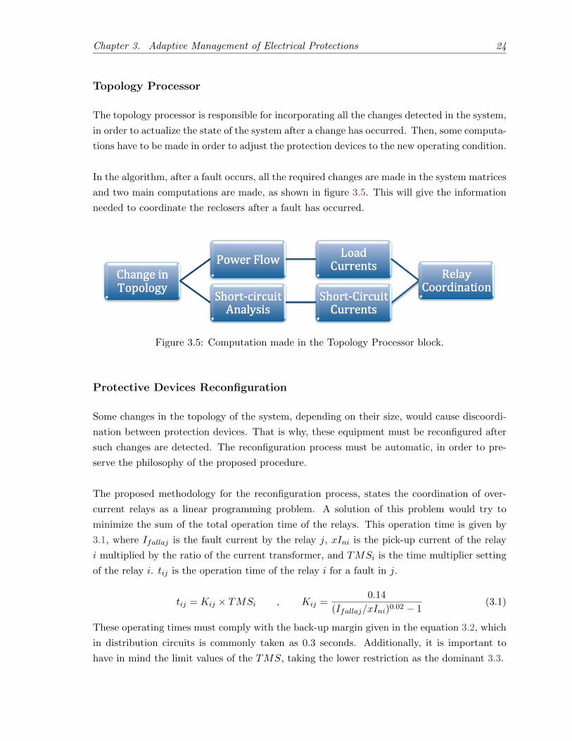
In the algorithm, after a fault occurs, all the required changes are made in the system matrices
and two main computations are made, as shown in figure 3.5. This will give the information
needed to coordinate the reclosers after a fault has occurred.
Figure 3.5: Computation made in the Topology Processor block.
Protective Devices Reconfiguration
Some changes in the topology of the system, depending on their size, would cause discoordi-
nation between protection devices. That is why, these equipment must be reconfigured after
such changes are detected. The reconfiguration process must be automatic, in order to pre-
serve the philosophy of the proposed procedure.
The proposed methodology for the reconfiguration process, states the coordination of over-
current relays as a linear programming problem. A solution of this problem would try to
minimize the sum of the total operation time of the relays. This operation time is given by
3.1, where Ifallaj is the fault current by the relay j, xIni is the pick-up current of the relay
i multiplied by the ratio of the current transformer, and TMSi is the time multiplier setting
of the relay i. tij is the operation time of the relay i for a fault in j.
tij = Kij × TMSi , Kij =0.14
(Ifallaj/xIni)0.02 − 1(3.1)
These operating times must comply with the back-up margin given in the equation 3.2, which
in distribution circuits is commonly taken as 0.3 seconds. Additionally, it is important to
have in mind the limit values of the TMS, taking the lower restriction as the dominant 3.3.
Chapter 3. Adaptive Management of Electrical Protections 25