Proceedings of 10 th International Heavy Haul Association Conference, New Delhi, India February 2013 160 TRACK & STRUCTURES TECHNICAL SESSION T5 – Track Health Monitoring & Rehabilitation Stress-Free temperature monitoring using different measuring technologies – experiences and assessment A. Wegner , Elektro-Thermit GmbH & Co.KG, D-06132 Halle, Germany 1. Short Description Longitudinal forces generated in continuously welded tracks due to temperature changes can lead to inadmissibly high tensile and compressive stresses. The Stress Free Temperature (SFT) defining the maximum and minimum upcoming stresses and acting as a key track parameter must be within given limits. Safety against buckles and breaks and ride comfort depend decisively on the SFT. Knowledge about track buckling fundamentals, interactions of the individual track parameter and particularities [1, 2] is essential for any best practice guideline to contol the longitudinal rail stresses to safe levels [3]. There are essentially three different track loads that can lead to stress development in rails: Temperature cycles, traffic and ground movements. In order to avoid inad- missibly decreased track stability due to these effects and to prevent consequences such as track buckles (Fig. 1), the SFT should be periodically maintained. Such preventive maintenance is only possible and cost-effective through the support of effective monitoring of the actual rail stresses and SFT. Several technologies were developed during the last decades to this end. Beside the conventional techniques of resistance and vibrating wire strain gauge monitoring systems, non- intrusive and non-destructive techniques like the micro-magnetic RAILSCAN method and its fur- ther development TRACKSAFE RELEASE can be applied. The article shows that these tech- nologies can complement each other if reasonably applied, leading to an effective SFT monitoring tool providing full value maintenance management. This combination can also facilitate and simplify the individual SFT measuring technologies, e.g. in view of system calibration. An assess- ment of the advantages, shortcomings, particularities and limits of the individual techniques is given, followed by applications combining these different techniques. Recent inspection examples on heavy haul and high-speed lines in railway networks worldwide are presented, where assur- ance that the cw track has been welded and subsists within the required stressing tolerance could be made by SFT measurements. Fig. 1: Picture of a transverse buckle near a switch due to inad- missible high longitudinal com- pressive load stresses resulting in a ballast resistance stability problem. In contrast to regular curves, often allowing a certain transverse displacement reducing the peak amplitude of compres- sive stress, the switch can act as a fixed point in the curve. The compressive stress enters the bucking regime, then finally ex- ceeds the strength against trans- verse track buckling. 2. Introduction The temperature associated with stress-free state “stress-free temperature” is usually not acces- sible by visual inspection and therefore has to be determined either by destructive tests, e.g. re- quiring a rail cut, or non-destructive methods. The task of determining the SFT acting in a rail of cw railway track is neither a simple technical problem nor a simple measuring task. The previ- ously used techniques for SFT can be divided into three groups and, for a better understanding of
Transcript
Proceedings of 10th International Heavy Haul Association Conference, New Delhi, India February 2013 160
Stress-Free temperature monitoring using different measuring technologies – experiences and assessment
A. Wegner, Elektro-Thermit GmbH & Co.KG, D-06132 Halle, Germany 1. Short Description Longitudinal forces generated in continuously welded tracks due to temperature changes can lead to inadmissibly high tensile and compressive stresses. The Stress Free Temperature (SFT)
defining the maximum and minimum upcoming stresses and acting as a key track parameter must be within given limits. Safety against buckles and breaks and ride comfort depend decisively on the SFT. Knowledge about track buckling fundamentals, interactions of the individual track parameter and particularities [1, 2] is essential for any best practice guideline to contol the longitudinal rail stresses to safe levels [3]. There are essentially three different track loads that can lead to stress development in rails: Temperature cycles, traffic and ground movements. In order to avoid inad-missibly decreased track stability due to these effects and to prevent consequences such as track buckles (Fig. 1), the SFT should be periodically maintained. Such preventive maintenance is only possible and cost-effective through the support of effective monitoring of the actual rail stresses and SFT. Several technologies were developed during the last decades to this end. Beside the conventional techniques of resistance and vibrating wire strain gauge monitoring systems, non-intrusive and non-destructive techniques like the micro-magnetic RAILSCAN method and its fur-ther development TRACKSAFE RELEASE can be applied. The article shows that these tech-nologies can complement each other if reasonably applied, leading to an effective SFT monitoring tool providing full value maintenance management. This combination can also facilitate and simplify the individual SFT measuring technologies, e.g. in view of system calibration. An assess-ment of the advantages, shortcomings, particularities and limits of the individual techniques is given, followed by applications combining these different techniques. Recent inspection examples on heavy haul and high-speed lines in railway networks worldwide are presented, where assur-ance that the cw track has been welded and subsists within the required stressing tolerance could be made by SFT measurements.
Fig. 1: Picture of a transverse buckle near a switch due to inad-missible high longitudinal com-pressive load stresses resulting in a ballast resistance stability problem. In contrast to regular curves, often allowing a certain transverse displacement reducing the peak amplitude of compres-sive stress, the switch can act as a fixed point in the curve. The compressive stress enters the bucking regime, then finally ex-ceeds the strength against trans-verse track buckling.
2. Introduction The temperature associated with stress-free state “stress-free temperature” is usually not acces-sible by visual inspection and therefore has to be determined either by destructive tests, e.g. re-quiring a rail cut, or non-destructive methods. The task of determining the SFT acting in a rail of cw railway track is neither a simple technical problem nor a simple measuring task. The previ-ously used techniques for SFT can be divided into three groups and, for a better understanding of
Proceedings of 10th International Heavy Haul Association Conference, New Delhi, India February 2013 161
the article, they are briefly listed and introduced below: a) measurement of the longitudinal rail load stress, b) measurement of the longitudinal rail force and c) measurement of elastic dilatation. For the determination of the SFT, all these methods also require the measurement of the rail tem-perature, which can be performed by contact or contactless standard techniques. Group a) -includes the x-ray stress determination techniques by measuring the lattice strains, the hole drill-ing method, in which the stress is determined by the stress change caused by a small borehole and measured by a strain gauge in circular configuration previously mounted on the place of the hole to be drilled, ultrasonic methods, in which the stress is determined by the measurement of stress-sensitive sound velocity and finally the micro-magnetic measurement methods, including e.g. RAILSCAN and TRACKSAFE RELEASE. Group b) includes the more complex vibration measurement techniques and the classical A-frame measurement techniques. The first includes an analysis of the harmonics for the stress determination and the latter can be considered as the quasi-static case of the vibrating methods. During the static measurement, the longitudinal rail force is determined by applying a well-defined, vertical lifting force on the rail unfastened on an also well-defined length. The additionally measured displacement of the rail during lifting enables the determination of the longitudinal rail force via elasticity theory. The measuring effect is that a rail within the required stress condition will generate a higher reaction force against the lifting dur-ing the measurement than does a rail in poor condition with a low SFT. With regard to the accep-tance and global distribution of this A-frame technique, given the lack of real non-destructive and non-intrusive methods during the past years, some features thereof will be assessed. This A-frame technique has the advantage that it does not depend on rail material and e.g. residual stresses. Significant limitations on practicality arise due to the requirement for rails to be meas-ured under tension stress and never under compressive stress, which means that the rail temperature must be below the SFT during any unfastening and measurement. Attention must also be paid to the fact that the longitudinal rail stress is calculated using the rail cross-sectional area and therefore is dependent on rail wear. Furthermore, the method is limited on straight rails and curves with larger radius, where for the latter a mathematical compensation of the measuring result must be included. Small curve radiuses cannot be measured. Group c) includes the classi-cal destructive methods, namely that of rail cut combined with the measurement of the gap size or strain change due to the rail contraction after the cut. The rail cut & strain gauge technology still represents the only conventional method, which is often used due to its general acceptance as a standard for comparison measurements for evaluating non-destructive techniques. It should be briefly mentioned that the strain gauge technology can also be applied without rail cut, namely, by suitable mounting of the strain gauge sensors on load stress-free rails before the establish-ment of stress condition. This variant is not suitable for inspection applications but useful for long time SFT observations. 3. RAILSCAN & TRACKSAFE RELEASE The RAILSCAN technique, enabling reliable non-destructive determination of the actual SFT of the track under traffic [4], has been further developed for track stability assessments. The measurement, to an accuracy of ±3° C and in special cases up to ±1 °C, can be made at any time without any rail unfastening. This also enables control of the SFT e.g. subsequent to the installa-tion of cw track. The correct neutralization can be checked and dangerous conditions with regard to possible changes of the actual SFT due to heavy track loading or extreme weather conditions can be identified. The history of RAILSCAN started with the introduction of the technique to the Hungarian railroad industry in the 1990s [5]. When the technology was originally introduced to the market in the early 2000s, its equipment possessed IT and electronic system solutions of the 90s. Therefore it has been upgraded continuously during the past years by an extensive modernization and optimiza-tion of hard- and software components. Milestones were reached in 2010 and 2011 by the development and realization of new electronical components and a measuring method adaptation eliminating the disturbe of remaining magnetism in rails and so avoiding the measurements to be inaccurate [5]. The new method recognizes any premagnetization in the rails and, thanks to the generation of energy-efficient and compensating magnetic fields as well as a new signal process-
Proceedings of 10th International Heavy Haul Association Conference, New Delhi, India February 2013 162
ing, remaining magnetism is eliminated by compensation and without requiring any demagnetiza-tion. Further to this, the mechanical components were also improved during the last years, e.g. the design of a probe for easier coupling in the height of worn rails. Practially all components have been revised, resulting in a robust, reliable and effective device. Additionally, the measuring procedure has also been improved. Initially in the 90s, the RAILSCAN technology was put into circulation featuring a so-called dual temperature measuring method. The essence of it is that the particular track section had to be measured twice on one and the same section at two different rail temperatures with at least 7 °C deviation. The change to mechanical stress caused by differ-ent temperatures improves measuring accuracy and provides an overview of the track’s condi-tion, e.g. “breathing” sections. For several reasons, e.g. the required extra time and thus lower customer acceptance, further the fact, that the required temperature difference doesn’t appear in certain climatic zones, throughout the year and among other things in tunnel constructions, from 2003/2004 on this procedure was replaced by the much easier “single temperature measuring procedure” including a calibration of the device on rail load stress in laboratory.
A b c d Fig. 2: Different design study results for next RAILSCAN generation. a: Result of pre-study with the aim of minimum intrusiveness “RAILSCAN LIGHT”. b: 2-wheel-trolley solution “Compact sledge”. c: 3-wheel-solution “Module trolley” . d: schlep solution “Monorail portable”. The TRACKSAFE RELEASE technique represents the further development of RAILSCAN and comprises a complete redesign (Fig. 2) of the used state-of-the-art application. Based on a redes-ign study, in which different solutions have been worked out and assessed, the trolley shown in Fig. 2b presented the best suitability for a device e. g. of lowest intrusiveness, convenient to in-corporate a complex probe, and thus was selected as final design. After completion intended in 2012, TRACKSAFE RELEASE will be offered as a complete SFT inspection service package as RAILSCAN today, leading to lower expenditure, high-precision measurements and the complete documentation of track conditions and safety. Both technologies, RAILSCAN and TRACKSAFE RELEASE are based on a micro-magnetic method where a known interaction between magnetic field and ferromagnetic material to be checked enables the determination of its stress state: The measuring principle applied takes into account the change in magnetic characteristics caused by mechanical stress (Villari effect) and its measurement by Magnetic Barkhausen Noise (MBN). A detailed description of the physical background is given in [6] . Further developments in the last years resulted in a light-weighted non-contact measuring device that allows fast measurement and documentation of the actual neutral temperature of most rail types. The longitudinal stress and the SFT are determined by evaluating the nd parameters. Inspection results are reliable and have been validated by measurement system capability investigations [4] and homologations, e.g. [6]. For producing MBN, the rail is energized in a direction perpendicular to the measured cross-sectional area and the magnetic Barkhausen noise emitted from the surface is measured. The MBN is measured at the surface with a sensor containing a ferromagnetic material, which is brought into contact with the surface to be measured. Imperfect matching due to unevenness of surface, scale, rust, contamination or paint coating increases the distance between probe and rail surface also known as air gap and is an error source reducing the magnitude of the detected MBN. In order to exclude this error source, the air gap is measured and, if it is too large, an alarm is given and the operator has to clean the rail surface or to select a different measuring point al-lowing a better coupling to the rail. By this way, the air gap is always kept within a small tolerance band to provide reliable magnitudes of the detected MBN according to the measured depth of the
Proceedings of 10th International Heavy Haul Association Conference, New Delhi, India February 2013 163
air gap. If a longitudinal stress is applied to the measured rail, the permeability for the applied magnetic field changes. Tension leads to an increase of permeability. The greater the longitudinal stress, the greater the increase of permeability. The opposite case applies when compressive stress is applied. With increasing compression, the magnetic field permeability decreases. The MBN contains the eddy currents of the stress-sensitive processes. Before measurement, the device is calibrated in the laboratory or on site using a mobile and port-able rail tensor and calibration rails. The rail tensor itself possesses a modified special design enabling the application of tensile and compressive stresses so that the whole measuring range can be calibrated and no extrapolation is required for the creation of the calibration curve. Meas-urements of the MBN are taken for different longitudinal stresses and used to plot a calibration curve of the MBN as a function of longitudinal stress. Before performing the calibration, the exci-tation parameters are also optimized and defined. Calibration curves and excitation parameters are then collected in a database and are available for all later measurements on the correspond-ing rail types. Thanks to the further developed and optimized calibration procedure, the complete calibration takes only approx. 1-2 hours. Further to this, the use of a new tensor device allows, together with the new device generation, much easier handling, the exclusion of operator influ-ence and higher accuracy. After this calibration step, the device is ready for the non-destructive measurement in tracks. Altogether 5 to 10 readings are distributed on a length 5 or 10 meters and consecutively taken and stored in the measuring computer resulting in one SFT value. For each of the 5 to 10 individual measurements the device is stopped above the measuring spot, then the probe is closed and the measurement taken. No recalibration of the different rail types is required because the device is equipped with a self-check utility and auto calibration routine, allowing monthly control of the correct functionality of the components. After completing the measure-ments, the SFT is determined and indicated on the computer screen of the device.
a b
Fig. 3: Different RailScan and TRACKSAFE RELEASE device design generations. a: RailScan 2009-2011 during SFT inspections in Halle Germany, b: TRACKSAFE RELEASE 2012 after full redesign during trials on German High Speed Line Nürnberg – Berlin construction site near Erfurt. Results are obtained by evaluating the measured values of the magnetic parameter and rail tem-perature: The magnetic parameter leads to the rail longitudinal load stress σ using the calibration curve stored in the device in form of a calibration table delivering the function between magnetic parameter and longitudinal load stress. The rail temperature measured on both sides of the upper part of the rail web and on the running surface by means of rail thermometers with a short raise time in contact technique is determined averaging the 3 individually measured rail temperatures.
Proceedings of 10th International Heavy Haul Association Conference, New Delhi, India February 2013 164
The neutral temperature (Stress-Free Temperature - SFT) is then calculated with the equation SFT = σ x E
-1 x α
-1 + TRail using the determined load stress σ, the known constants elasticity
modulus E and thermal expansion coefficient α and the determined rail temperature TRail. The re-sults of the inspected locations are summarized in a report containing all relevant track informa-tion, i.e. the measured SFT linked to their location and position in the cw-rail, see also detailed evaluation description given in [6]. 4. Further developments and extensive redesign – TRACKSAFE RELEASE
Fig. 3 gives an overview of the different device generations realized until today. The 2009-2011 generation of RAILSCAN (Fig. 3 a) already contained significant further developments, providing a waterproof function and minimization of errors due to the magnetic and electric properties of the rails to be measured: The waterproof function of the measuring computer and all device compo-nents sensitive against water and humidity like e.g. the battery, the probe, electronics and all ca-ble connectors is very important for a reliable use of the device under different weather conditions and was realized by means of implementing individual sealing techniques for these components. The exclusion of errors due to pre-magnetization effects in the rail is performed by means of a compensation procedure (see paragraph 3 and [5]) and the exclusion of disturbance effects due to electrical currents in the rail is realized using corresponding band pass filters. For the further development of the new TRACKSAFE RELEASE device generation an extensive analysis of the required functionality has been performed resulting in an appropriate complete device redesign (Fig. 3 b). Consequently, all achieved developments and optimizations have been collected in the new TRACKSAFE RELEASE device generation providing advantages over former state-of-the-art applications; to name just a few examples, one universal probe for all rail types, optimized stabil-ity of probe closing during inspection and thus higher reliability or enlargement of potential meas-uring time. Detailed performance and disturbance investigations have been internally carried out, documented [7] and are actually internally pursued until termination of development works. 5. Application fields and state-of-the-art in practice Thanks to its flexibility, TRACKSAFE RELEASE is versatile and allows widespread use. Exam-ples are SFT determination for minimizing the areas to be maintained, the detection of locations in which quality and safety are endangered, the determination of zone length affected by rail buckles, fractures and derailment as well as the verification and documentation of cw-rail produc-tion, assuring that the cw track has been distressed within the required stressing tolerance ex-cluding any subsequent re-establishment of required stress conditions. During the last years, ex-tensive practical experiences could be collected during different inspection and development projects, e.g. in Europe, the U.S. and in Australia [4, 6]. Regular RailScan inspection works have been performed in different applications since 2006. A very interesting perspective for the de-ployment of the technique is given in France where the technique is used for SFT determination under the names RAILSCAN and BoaScan (SNCF) [8] e.g. after track renewal and assuring that the continuously welded high-speed track was welded within the required stressing. For the latter application, a measurement at zero load stress is integrated in the measuring procedure provid-ing an increase of the SFT measuring accuracy up to smaller than ±1°C. In Denmark, inspections were performed on heavily loaded main-line tracks as well as interurban railways since 2005. Due to the experiences and various investigations according to recognized standards and practical comparison measurements, the RAILSCAN and TRACKSAFE RELEASE technique could be ap-proved as a reliable and satisfactory technique for SFT determination; it was admitted in Bane-danmarks directives for the production of cw rails (2007) and has been definitively approved in 2010 by Banedanmark [9]. In 2011, one of the 17km-long sectors of the EUROTUNNEL, linking France with the United Kingdom was SFT inspected with RAILSCAN (Fig. 4). Large inspection projects were implemented for the Turkish State Railways in Anatolia, where several High Speed Lines have been realized during the past few years. The newest HSL was opened in 2011. Their construction technology, details and particularities including special components like switches & crossings are presented in [10]. In order to make sure that all works of have been executed with a re-establishment of correct stress condition, Elektro-Thermit started with SFT inspections on
Proceedings of 10th International Heavy Haul Association Conference, New Delhi, India February 2013 165
Turkish High Speed Lines. In 2011, more than 200 km of double track were inspected with RAILSCAN on the high-speed line HSL Ankara - Eskisehir. The SFT inspections were performed during approx. 60 night shifts leading to more than 1,300 SFT results. Follow up inspection pro-jects of even larger order are under preparation. Regular RAILSCAN SFT inspections also take place in Ireland for several years enabling non-destructive SFT condition monitoring on different locations and components including S&C.
a b Fig. 4: RAILSCAN SFT inspections in the EUROTUNNEL Calais-Folkestone. a: Underground twin tube tunnel portal at the French side near Calais. b: Terminal loops with above ground tunnel on the UK side at Folkestone. 6. Combination of different SFT inspection techniques
The experiences made with RAILSCAN in the last few years have shown the advantages of tech-nology and confirmed them in the long-term. It also showed that the effectiveness and swiftness of inspections can generally depend on the type of section to be measured, the superstructure, the track category and the maintenance properties. It became apparent that some new stretches of track and particularly high-speed rail lines for example could be measured particularly easily, if they primarily feature the same types, grades and manufacturers of tracks, and with the same rail marking for many kilometres in special cases. Since it can be measured with one device setting and calibration only in these cases, the measurement performance is increased and the pre-paratory works for device calibration are accordingly negligible low. However, this easiest case for the RAILSCAN measurement in international railway networks is not the rule, but rather the exception in comparison to the global railway networks. That is why RAILSCAN devices are equipped with a database of various device settings and calibrations, which can be called up for the measurement as needed. Approx. 80% of the measurings could be covered with this device preparation in an ideal situation. However, it is important to indicate here, that a database includ-ing all various device settings and calibration curves is not available for SFT measurements ac-cording to the actual state-of-the-art of today. The problem to achieve this is due to the material influence and the unknown residual stresses of older rails, for which calibration rail pieces for calibration are not available. Existing calibration curves and settings of comparable rail grades used for this purpose could deviate from the required resulting in measuring errors. For medium-term future applications it is conceivable that adequate knowledge resulting in a compensating correction would enable the preparation of a database for all types of rail available on a railway system. Nevertheless, at the present day, depending on the project it can come to a situation on site, where old tracks cannot be measured immediately due to unknown types of tracks, since no calibration curves of the respective type of track are available or can be called up. In these cases, the application procedure plans for a calibration on a similar track sample in the mobile rail tensor device. This step, of course, consumes time, means effort and therefore it is usually unwanted in the project. A combination of e.g. the abovementioned A-frame method with RAILSCAN can be used as remedy on request. As this method does not require a material-specific calibration, a reference measuring for RAILSCAN can be conducted by measuring the SFT at the unknown type of track, where this can be set up and calibrated to the alternatively determined SFT and it
Proceedings of 10th International Heavy Haul Association Conference, New Delhi, India February 2013 166
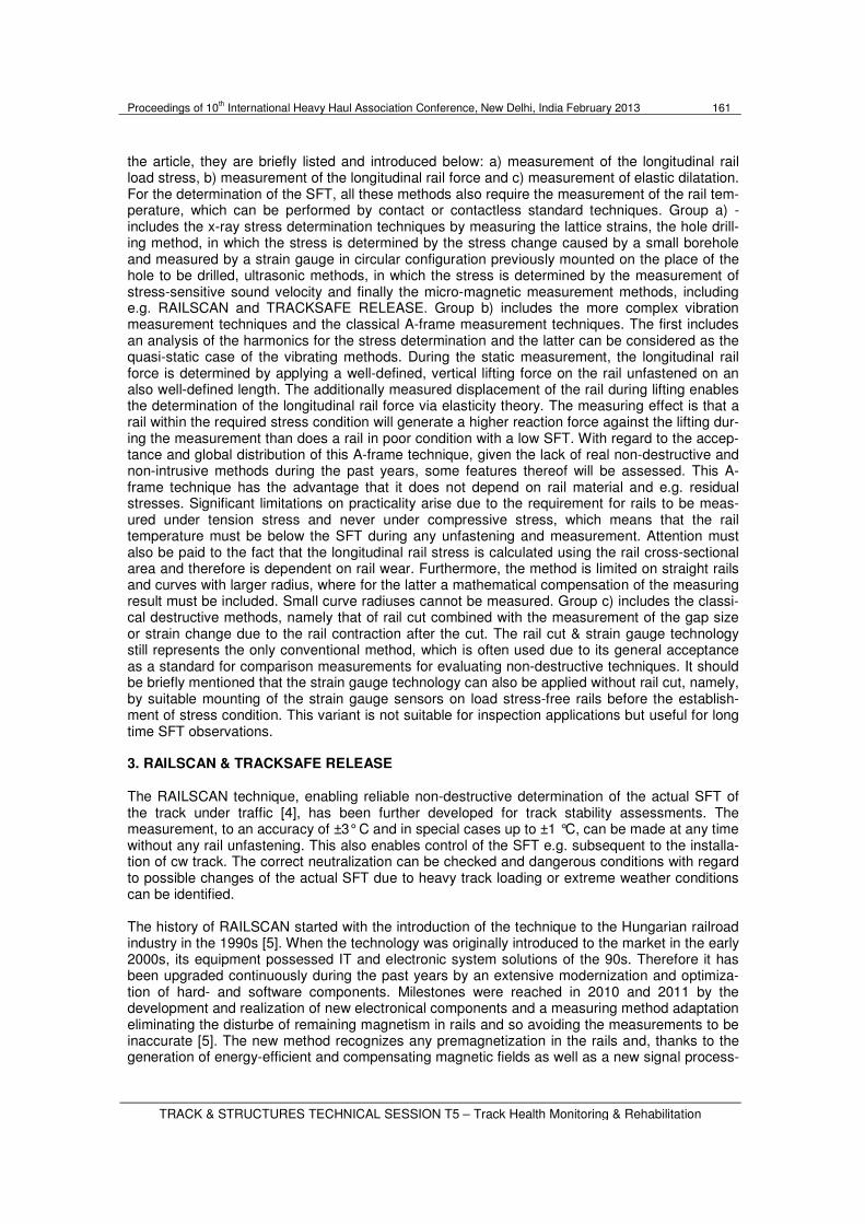
will be ready for measure immediately. Especially for lines with older types of tracks this addition of two methods constitutes a considerable potential for enhancement of the speed of inspection, because the more time-consuming and intrusive A-frame method is only used at certain measur-ing points and the faster and nonintrusive measuring with RAILSCAN is pulled up as a gap clo-sure for SFT documentation of entire track sections. Fig. 5 shows an exemplary visualization for the combination of RAILSCAN and A-frame of Australia, where the two techniques also have been used for comparison investigations between each other resulting in a practical experience collection not least regarding different rail stress and temperature measuring.
Fig. 5: Picture of a trial in Broken Hill, Australia. On an A.R.T.C railway line comparative as well as sup-plementary measurements between RAILSCAN and A-frame SFT equipment were performed in order to study not only the capability of the two methods but also the possibilities of increasing the SFT inspection performance in different situations under different random conditions. Attention also has been paid to SFT measurement in narrow curves & sections with decreased ballast density.
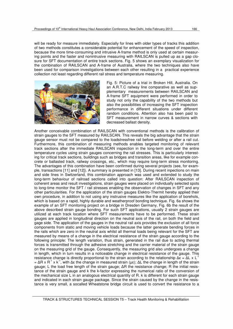
Another conceivable combination of RAILSCAN with conventional methods is the calibration of strain gauges to the SFT measured by RAILSCAN. This reveals the big advantage that the strain gauge sensor must not be compared to the loadstressfree rail before welding or after a rail cut. Furthermore, this combination of measuring methods enables targeted monitoring of relevant track sections after the immediate RAILSCAN inspection in the long-term and over the entire temperature cycles using strain gauges concerning the rail stresses. This is particularly interest-ing for critical track sections, buildings such as bridges and transition areas, like for example con-crete or ballasted track, railway crossings, etc., which may require long-term stress monitoring. The advantages of this combination have been confirmed during several projects (see, for exam-ple, transactions [11] and [12]). A summary is presented in [13]. During recent inpections on main and side lines in Switzerland, this combination approach was used and extended to study the long-term behaviour of railroad sections called into question: After RAILSCAN inspection of coherent areas and result investigations, strain gauges were placed on individually selected spots to long-time monitor the SFT / rail stresses enabling the observation of changes in SFT and any other particularities. For the application of the strain gauges Elektro-Thermit hereby applied their own procedure, in addition to not using any instrusive measures like the application of borehols, which is based on a rapid, highly durable and weatherproof bonding technique. Fig. 6a shows the example of an SFT monitoring project on a bridge in Dresden Germany, Fig. 6b the result of the above described strain gauge bonding. For such SFT applications, usually 2 strain gauges are utilized at each track location where SFT measurements have to be performed. These strain gauges are applied in longitudinal direction on the neutral axis of the rail, on both the field and gage side. The application of the gauges in the neutral rail axis provides the exclusion of all force components from static and moving vehicle loads because the latter generate bending forces in the rails which are zero in the neutral axis whilst all thermal loads being relevant for the SFT are measured by means of a change in the electrical resistance of the strain gauge according to the following principle: The length variation, thus strain, generated in the rail due to acting thermal forces is transmitted through the adhesive stretching and the carrier material of the strain gauge on the measuring grid of the gauge. Consequently, the measuring grid also undergoes a change in length, which in turn results in a noticeable change in electrical resistance of the gauge. This resistance change is directly proportional to the strain according to the relationship ∆ε = ∆L x L
-1
= ∆R x R-1
x k-1
, with ∆ε the change in measured strain (µε); ∆L the change in length of the strain gauge; L the load free length of the strain gauge; ∆R the resistance change; R the initial resis-tance of the strain gauge and k the k-factor expressing the numerical ratio of the conversion of the mechanical size L in an analogous electrical quantity of R. k is different for each strain gauge and indicated in each strain gauge package. Since the strain caused by the change in the resis-tance is very small, a socalled Wheatstone bridge circuit is used to convert the resistance to a
Proceedings of 10th International Heavy Haul Association Conference, New Delhi, India February 2013 167
change in voltage, where for our applications the Wheatstone bridge is used in a three-wire quarter bridge connection with a single active strain gauge in uni-axial tension or compression. After measurement completion and data storage the data can be forwarded either via cables or wire-less radio technology to a base station which forwards the data for its part to a central server unit in which evaluation and an alarm function can be provided. The power supply of the compo-nents Wheatstone Bridge and base station can be provided either by batteries, AC mains power supply or by solar power storage units. The particular character of strain gauge bonding to be less intrusive than current intrusive strain gauge technique leads us to expect that this technology will become more enlisted, all the more so because wireless techniques for data collection and their remote transmission to a central computer or server in the control room are available enabling extensive monitoring and so rapid actions in cases of need. Finally, the deployment of this state-of-the-art contributes to the reduc-tion of expenditure and costs of condition monitoring integrated systems and components like e.g. presented in [14] also of course, for theft prevention.
a b
Fig. 6: Example of rail longitudinal stress monitoring. a: Site view of the monitored railway and road bridge across the Elbe. b: Applied strain gauge in bonding technique and completed wea-therproof protection; The white box represents a protection for connection components. The comparison between the characteristics of current SFT measuring methods already showed in the recent past (refer e.g. to [4]) that RAILSCAN possesses outstanding properties enabling an unprecedented cost-effective and efficient longitudinal force management. By the combination of the above treated different methods SFT inspection becomes rather effective enabling RAILSCAN measurement also in border cases and providing the advantages of each individual method to SFT inspection whilst their individual weaknesses and disadvantages are compen-sated by the combination. The measuring accuracy of RAILSCAN within ±3° C is largely satis-factory to detect limited track safety / critical areas, nevertheless its accuracy can be verified and increased calibrating it on A-frame or strain gauge SFT results. Then a complete track safety documentation is provided by non-destructive RAILSCAN inspection with the following advan-tages that can not be achieved by the other methods: Measurements of tensile and compressive stresses, reliable measurements at any hour and under any weather conditions, measurements without any rail unfastening, no SFT modification by means of the measurement, no danger of injury from the sudden buckling, e.g. after unfastening rails under compressive stress, light weight technique and easy to use without any required customer staff, usable without possession and at short date without any company ruling. Finally the special advantage of strain gauge monitoring recording entire daily temperature cycles can provide added value and can be applied less intru-sive if a gauge calibration on RAILSCAN SFT is achieved. 7. Conclusion
The article introduces different SFT techniques and in particular presents the state-of-the-art of the non-destructive and micro-magnetic SFT inspection RAILSCAN technique as well as its fur-
Proceedings of 10th International Heavy Haul Association Conference, New Delhi, India February 2013 168
ther development TRACKSAFE RELEASE technologies, which enable measurement of the stress-free temperature SFT of stressed track during operation without intervention in the track. This prevents the need for time-consuming, complicated and hence expensive alternative meth-ods that necessarily involve intervention in the cw track. By enabling an evaluation of track quality and safety, these micro-magnetic technologies contribute to forward-looking and timely mainte-nance management, significantly reducing maintenance costs. In certain borderline cases, it is promising to combine different SFT technologies presented at the beginning because they can complement each other if reasonably applied, leading to an effective SFT monitoring tool provid-ing a full value maintenance management. This is much more advantageous than focusing only on one measuring technique, because this combination allows an increase in reliability and in-spection performance and therefore enables an optimal maintenance and cost reduction. 8. References
[1] A. D. Kerr, “THERMAL BUCKLING OF STRAIGHT TRACKS FUNDAMENTALS, ANALYSIS, AND PREVENTIVE MEASURES”, Report No. FRA/ORD-78/49, National Technical Information Service Springfield, Virginia 22151, September 1978.
[2] J. Eisenmann, “Track Stability of HSL lines under of (In German)”, EI-Eisenbahningenieur, pages 18, 5/2002.
[3] A. Kish, “FUNDAMENTALS OF RAIL STRESS MANAGEMENT IN CWR”, Wheel Rail Interac-tion Conference, Proceedings Heavy Haul Seminar, Chicago, USA, May 2010
[4] A. Wegner, “Quality Assessment of Continuously Welded Tracks by Nondestructive Testing of Stress-Free Temperature SFT”, Proceedings of International Heavy Haul Conference, Shang-hai, China, pages 198-204, 2009.
[5] G. Posgay, P. Molnár, A. Wegner, “RAILSCAN SFT INSPECTION - DEVELOPMENTS AND RESULTS”, World of Rails (Sinek Világa, In Hungarian), Budapest, pages 28-32, February 2012.
[6] A. Wegner, “Prevention of Track Buckling and Rail Fracture by Non-destructive Testing of the Neutral Temperature in cw-Rails”, Proceedings International Heavy Haul Conference 2007, Spe-cialist Technical Session, Kiruna, Sweden, pages 557-564, 2007.
[7] B. Dreilich, “Disturbance influences and optimization potentials for TRACKSAFE RELEASE (In German)”, Master Thesis, Confidential, University of Applied Sciences Merseburg, Dec. 2011.
[8] Definite homologation of stress-free temperature equipment RAILSCAN, letter of IGEV / ET / 2011.006/ IN3590 - Homologation ET N°293.2011, St. Denis, 2011-04-04, France.
[9] RailScan/TRACKSAFE RELEASE CERTIFICATE OF ACCEPTANCE as railway superstruc-ture measuring device for SFT determination, banedanmark, Copenhagen, September 2010.
[10] E. Demirel, “Construction of High Speed Line Ankara - Konya from the view of executing su-perstructure welding company (In German)”, Proceedings GSI SLV, 6
th Congress of Superstruc-
ture Welding Technique, Hannover, September 2011.
[11] R. Ende, A. Wegner, “Investigations of SFT and optimization of maintenance costs in cw track (In German)”, 11
th Railroad Construction Circle RAILBETON
® Plants, Chemnitz, 3/2008.
[12] P. Kilian, H.-O. Cramer, A. Wegner, “Non-destructive monitoring of longitudinal rail stresses under the Leipzig City Tunnel Project (In German)“, 7
th Train Council Chemnitz, March 2008.
[13] A. Wegner: „ND-RAILSCAN-SFT-Inspection (In German)“, El-Eisenbahningenieur, pages 38-42, 11/2008.
[14] P.J. Gräbe et al., „An intelligent condition Monitoring System for the Management of Conti-nuously Welded Rails”, Proceedings International Heavy Haul Conference 2007, Specialist Tech-nical Session, Kiruna, Sweden, pages 579-586, 2007.